WO2023181171A1 - Inkjet recording device and inkjet recording system - Google Patents
Inkjet recording device and inkjet recording system Download PDFInfo
- Publication number
- WO2023181171A1 WO2023181171A1 PCT/JP2022/013508 JP2022013508W WO2023181171A1 WO 2023181171 A1 WO2023181171 A1 WO 2023181171A1 JP 2022013508 W JP2022013508 W JP 2022013508W WO 2023181171 A1 WO2023181171 A1 WO 2023181171A1
- Authority
- WO
- WIPO (PCT)
- Prior art keywords
- ink
- inkjet recording
- print head
- main body
- head
- Prior art date
Links
- 238000004140 cleaning Methods 0.000 claims abstract description 187
- 239000002245 particle Substances 0.000 claims abstract description 87
- 238000012790 confirmation Methods 0.000 claims abstract description 38
- 239000002904 solvent Substances 0.000 claims description 151
- 239000007788 liquid Substances 0.000 claims description 87
- 230000005856 abnormality Effects 0.000 claims description 70
- 238000001514 detection method Methods 0.000 claims description 62
- 238000011084 recovery Methods 0.000 claims description 54
- 238000007639 printing Methods 0.000 claims description 44
- 230000005540 biological transmission Effects 0.000 claims description 25
- 238000005259 measurement Methods 0.000 claims description 18
- 230000001276 controlling effect Effects 0.000 claims description 13
- 238000010438 heat treatment Methods 0.000 claims description 11
- 230000001105 regulatory effect Effects 0.000 claims description 6
- 238000007599 discharging Methods 0.000 claims description 4
- 238000000034 method Methods 0.000 abstract description 206
- 230000008569 process Effects 0.000 abstract description 198
- 238000012423 maintenance Methods 0.000 abstract description 20
- 238000012545 processing Methods 0.000 description 32
- 238000010586 diagram Methods 0.000 description 26
- 238000012544 monitoring process Methods 0.000 description 23
- 239000007789 gas Substances 0.000 description 21
- 238000007641 inkjet printing Methods 0.000 description 14
- 238000004891 communication Methods 0.000 description 12
- 230000006870 function Effects 0.000 description 11
- 238000001035 drying Methods 0.000 description 7
- 230000007274 generation of a signal involved in cell-cell signaling Effects 0.000 description 7
- 238000009434 installation Methods 0.000 description 7
- 238000003780 insertion Methods 0.000 description 6
- 230000037431 insertion Effects 0.000 description 6
- 238000004519 manufacturing process Methods 0.000 description 5
- 230000007423 decrease Effects 0.000 description 4
- 230000000694 effects Effects 0.000 description 4
- 238000005192 partition Methods 0.000 description 4
- 230000001681 protective effect Effects 0.000 description 4
- 238000005086 pumping Methods 0.000 description 4
- 230000004044 response Effects 0.000 description 4
- 230000002159 abnormal effect Effects 0.000 description 3
- 238000005452 bending Methods 0.000 description 3
- 239000012530 fluid Substances 0.000 description 3
- 239000000976 ink Substances 0.000 description 3
- 230000015654 memory Effects 0.000 description 3
- 238000003860 storage Methods 0.000 description 3
- 238000010792 warming Methods 0.000 description 3
- 230000009471 action Effects 0.000 description 2
- 230000003321 amplification Effects 0.000 description 2
- 238000013459 approach Methods 0.000 description 2
- 238000005516 engineering process Methods 0.000 description 2
- 230000005284 excitation Effects 0.000 description 2
- 230000000977 initiatory effect Effects 0.000 description 2
- 238000012986 modification Methods 0.000 description 2
- 230000004048 modification Effects 0.000 description 2
- 238000003199 nucleic acid amplification method Methods 0.000 description 2
- 238000005507 spraying Methods 0.000 description 2
- 238000005406 washing Methods 0.000 description 2
- 239000000919 ceramic Substances 0.000 description 1
- 230000008859 change Effects 0.000 description 1
- 238000006243 chemical reaction Methods 0.000 description 1
- 230000003247 decreasing effect Effects 0.000 description 1
- 239000000428 dust Substances 0.000 description 1
- 238000007667 floating Methods 0.000 description 1
- 235000013305 food Nutrition 0.000 description 1
- 230000005484 gravity Effects 0.000 description 1
- 239000004973 liquid crystal related substance Substances 0.000 description 1
- 230000007246 mechanism Effects 0.000 description 1
- 239000002184 metal Substances 0.000 description 1
- 239000000203 mixture Substances 0.000 description 1
- 238000003825 pressing Methods 0.000 description 1
- 230000000717 retained effect Effects 0.000 description 1
- 239000007921 spray Substances 0.000 description 1
- 239000000126 substance Substances 0.000 description 1
- 230000007704 transition Effects 0.000 description 1
Images


Classifications
-
- B—PERFORMING OPERATIONS; TRANSPORTING
- B41—PRINTING; LINING MACHINES; TYPEWRITERS; STAMPS
- B41J—TYPEWRITERS; SELECTIVE PRINTING MECHANISMS, i.e. MECHANISMS PRINTING OTHERWISE THAN FROM A FORME; CORRECTION OF TYPOGRAPHICAL ERRORS
- B41J2/00—Typewriters or selective printing mechanisms characterised by the printing or marking process for which they are designed
- B41J2/005—Typewriters or selective printing mechanisms characterised by the printing or marking process for which they are designed characterised by bringing liquid or particles selectively into contact with a printing material
- B41J2/01—Ink jet
- B41J2/015—Ink jet characterised by the jet generation process
- B41J2/02—Ink jet characterised by the jet generation process generating a continuous ink jet
-
- B—PERFORMING OPERATIONS; TRANSPORTING
- B41—PRINTING; LINING MACHINES; TYPEWRITERS; STAMPS
- B41J—TYPEWRITERS; SELECTIVE PRINTING MECHANISMS, i.e. MECHANISMS PRINTING OTHERWISE THAN FROM A FORME; CORRECTION OF TYPOGRAPHICAL ERRORS
- B41J2/00—Typewriters or selective printing mechanisms characterised by the printing or marking process for which they are designed
- B41J2/005—Typewriters or selective printing mechanisms characterised by the printing or marking process for which they are designed characterised by bringing liquid or particles selectively into contact with a printing material
- B41J2/01—Ink jet
- B41J2/07—Ink jet characterised by jet control
- B41J2/075—Ink jet characterised by jet control for many-valued deflection
- B41J2/08—Ink jet characterised by jet control for many-valued deflection charge-control type
-
- B—PERFORMING OPERATIONS; TRANSPORTING
- B41—PRINTING; LINING MACHINES; TYPEWRITERS; STAMPS
- B41J—TYPEWRITERS; SELECTIVE PRINTING MECHANISMS, i.e. MECHANISMS PRINTING OTHERWISE THAN FROM A FORME; CORRECTION OF TYPOGRAPHICAL ERRORS
- B41J29/00—Details of, or accessories for, typewriters or selective printing mechanisms not otherwise provided for
- B41J29/38—Drives, motors, controls or automatic cut-off devices for the entire printing mechanism
Definitions
- the present invention relates to a continuous jet inkjet recording device and an inkjet recording system.
- Patent Document 1 describes an ink container that stores ink for printing on a printing target, a nozzle that is connected to the ink container and that ejects pressurized ink, and ink particles that are ejected from the nozzle.
- a charging electrode that charges the charging electrode; a charging signal generating unit that generates a charging signal that charges the charging electrode; a deflection electrode that deflects ink particles charged with the charging electrode; and a gutter that collects ink that is not used for printing; a control section that controls the overall operation; and a first charge detection means that detects the amount of charge caused by charging the ink particles between the charging electrode and the deflection electrode; and a first charge detection means that detects the amount of charge of the ink flowing in the gutter.
- An inkjet recording apparatus having a second charge detection means is disclosed.
- Patent Document 2 includes a print head that receives a supply of ink and performs printing, an ink container for accommodating the ink, and a solvent container for accommodating a solvent, and the ink in the ink container is supplied to the print head.
- the print head has a nozzle that ejects ink as ink particles, a charging electrode that charges the ink particles ejected from the nozzle in accordance with the content to be printed, and a print head that discharges the ink as ink particles.
- An inkjet recording system that includes a head cleaning unit that includes a cleaning nozzle that sprays solvent toward the cleaning tank, a recovery container that is installed at the bottom of the cleaning tank and that collects the solvent after cleaning, and a drive unit that supplies the solvent to the cleaning nozzle.
- Patent Document 2 discloses that during a period when a print head is installed, ink in an ink container is supplied to a nozzle at regular intervals, and ink particles ejected from the nozzle are collected by a gutter and returned to the ink container.
- An inkjet recording device that is controlled to collect ink is disclosed.
- Patent Document 1 describes the configuration and control method of an inkjet recording apparatus for detecting an abnormality (generally referred to as beam bending) in which ink particles ejected from a nozzle of a print head cannot be captured by a gutter. .
- beam bending an abnormality
- Such an abnormality (beam bending) may occur immediately after the nozzle starts ejecting ink (at the start of operation), and when an abnormality (beam bending) occurs, there is a risk of contaminating the area around the print head with ink. There is. Therefore, it is necessary to clean this contaminated ink.
- Patent Document 2 discloses that a solvent is discharged from a cleaning nozzle to a print head installed in a head cleaning unit to clean ink stains from the print head, and then air is discharged from an air nozzle to clean the print head.
- the structure and control method of an inkjet recording apparatus for drying attached solvent is described.
- Patent Document 2 With the print head attached to a head cleaning unit, ink is jetted from the nozzles of the print head periodically at intervals of about once every two to three days for maintenance management, and the ink is washed into the gutter.
- a cleaning process that collects and circulates the ink, problems such as ink sticking are reduced the next time it is used (at the start of operation).
- Operational information of such automatic ink circulation processing (such as whether an abnormality has occurred) can be confirmed from the operation screen of the inkjet recording apparatus.
- maintenance management of the print head is performed by an operator operating (pressing) a button arranged on the operation screen of the inkjet recording apparatus.
- a print head cleaning process may be required before each start of operation (before ink is ejected from the nozzles). In this case, workers must go to the location where the inkjet recording device is installed each time, but in large-scale factories where multiple inkjet recording devices are used, this becomes troublesome and requires a lot of work. It will cost you work time.
- An object of the present invention is to provide an inkjet recording device and an inkjet recording system that can remotely perform maintenance management such as print head cleaning processing.
- Another object of the present invention is to enable operation information to be checked remotely when automatic ink circulation processing is being carried out periodically, and to notify a worker to take corrective action if there is an abnormality.
- An object of the present invention is to provide an inkjet recording device and an inkjet recording system that can perform the following steps.
- the first feature of the present invention is A nozzle that ejects the supplied ink into particles, a charging electrode that charges the ink particles ejected from the nozzle, a deflection electrode that deflects the ink particles charged by the charging electrode, and collects unused ink that is not used for printing.
- a print head having a gutter; An ink supply path for supplying ink in the ink container to the print head, an ink recovery path for collecting ink not used for printing into the ink container, and a solvent supply path for supplying the solvent in the solvent container to the ink container.
- a body comprising channels and regulators for regulating the flow of ink and solvent in the respective channels; an adjustment section of the main body and a main body control section that controls the operation of the print head;
- An inkjet recording device comprising a head mounting part for mounting and storing a print head, and a head mounting unit having a print head detector for detecting that the print head is mounted,
- the main body control unit includes a transmission unit that transmits head attachment detection information indicating that the print head is attached to the head attachment unit based on a detection signal from the print head detector to an external control device connected via a network. It is equipped with the following.
- the second feature of the present invention is An inkjet recording system comprising an inkjet recording device, a server connected to the inkjet recording device, a network to which the server is connected, and an external control device connected to the network and controlling the inkjet recording device via the server,
- the inkjet recording device is A nozzle that ejects the supplied ink into particles, a charging electrode that charges the ink particles ejected from the nozzle, a deflection electrode that deflects the ink particles charged by the charging electrode, and collects unused ink that is not used for printing.
- a print head having a gutter;
- a main body including a flow rate adjusting section that adjusts the flow of ink and solvent in the respective paths; a main body control section that controls the flow rate adjustment section of the main body and the operation of the print head;
- a head mounting unit for mounting and accommodating a print head, and a head mounting unit having a print head detector for determining whether or not the print head is mounted,
- the external control device is
- a head attachment confirmation means is provided that can confirm that the print head is attached to the head attachment unit based on head attachment detection information transmitted from the main body control unit indicating that the print head is attached to the head attachment unit. It's where you are.
- the operation information can be checked remotely, and if there is an abnormality, the operator can be contacted to request corrective action.
- FIG. 1 is a configuration diagram showing an overall outline of an inkjet recording apparatus and an inkjet recording system according to a first embodiment of the present invention.
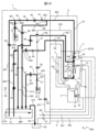
- 2 is a route configuration diagram showing the configuration of an ink supply route of the inkjet recording apparatus in FIG. 1.
- FIG. 2 is a block diagram showing the configuration of the inkjet recording apparatus in FIG. 1.
- FIG. 2 is a configuration diagram showing the configuration of the head mounted unit of FIG. 1 with a collection container removed.
- FIG. 2 is a configuration diagram showing a state in which a collection container and a print head are installed in the head installation unit of FIG. 1; 2 is an explanatory diagram illustrating the flow of operations and monitoring in the inkjet recording system of FIG. 1.
- FIG. 1 is a configuration diagram showing an overall outline of an inkjet recording apparatus and an inkjet recording system according to a first embodiment of the present invention.
- 2 is a route configuration diagram showing the configuration of an ink supply route of the inkjet recording apparatus in FIG. 1.
- FIG. 2 is an explanatory diagram illustrating operations and a monitoring screen displayed on the external control device of FIG. 1.
- FIG. FIG. 3 is a flowchart illustrating operation start processing in the print head.
- FIG. 2 is a route configuration diagram illustrating the flow of liquids such as ink and solvent, and gases such as air and volatile gas (indicated by thick lines) when an operation start process is performed.
- FIG. 3 is a flowchart diagram illustrating operation stop processing in the print head.
- FIG. 2 is a path configuration diagram illustrating the flow of liquids such as ink and solvent, and gases such as air and volatile gas (indicated by thick lines) when an operation stop process is performed.
- FIG. 3 is a flowchart illustrating head cleaning processing in a print head.
- FIG. 3 is a path configuration diagram illustrating the flow of liquids such as ink and solvent, and gases such as air and volatile gas (indicated by thick lines) when a head cleaning process is performed.
- FIG. 6 is an explanatory diagram illustrating a state in which a collection container contains a large amount of cleaning liquid in the head mounted unit.
- FIG. 3 is a flowchart illustrating automatic ink circulation setting processing in the print head.
- FIG. 3 is a path configuration diagram illustrating the flow of ink, liquids such as solvents, and gases such as air and volatile gases (indicated by thick lines) when automatic ink circulation setting processing is performed. It is a block diagram which shows the outline of the whole inkjet recording device and inkjet recording system in the 2nd Embodiment of this invention.
- FIG. 19 is a block diagram which shows the outline of the whole inkjet recording device and inkjet recording system in the 3rd Embodiment of this invention. 19 is an explanatory diagram illustrating the flow of operations and monitoring in the inkjet recording system of FIG. 18.
- FIG. 19 is an explanatory diagram illustrating the flow of operations and monitoring in the inkjet recording system of FIG. 18.
- FIG. 1 is a perspective view showing how an inkjet recording apparatus according to a first embodiment of the present invention is used.
- an inkjet recording system 501 includes an inkjet recording device 600A or 600B, an IoT site server 9 connected to the inkjet recording device 600 by a cable 10, and an external control device that performs wireless communication with the IoT site server 9 via a network 14. 100.
- Inkjet recording devices 600A and 600B each include a main body 1, a print head 2 connected to the main body 1 by a cable (for print head) 5, and a head connected to the main body 1 by a cable (for head attachment unit) 6.
- a mounting unit 3 is provided.
- the head mounting unit 3 basically has the function of accommodating the print head, but may also have an additional function of cleaning the print head by spraying a cleaning liquid.
- the head mounting unit 3 described below has a configuration in which a function for cleaning the print head is added.
- the inkjet recording device 600A shows a state in which the print head 2 is installed on a production line. Further, the inkjet recording apparatus 600B is shown with the print head 2 removed from the production line and mounted on the head mounting unit 3. Note that the recovery container 4 attached to the lower part of the head mounting unit 3 is provided to contain the cleaning liquid after the print head is washed by the head mounting unit 3.
- the inkjet recording device 600A is installed, for example, on a production line in a factory where foods, drinks, etc. are produced, and the main body 1 is installed in a location where the space necessary for regular maintenance work can be secured.
- the print head 2 is fixed to a support fitting 13 installed near the belt conveyor 11, and is used to print on print objects 12A and 12B that are fed in the direction of arrow X on a production line such as the belt conveyor 11. are located close together.
- a protective cover 95 is attached to the print head 2 for the purpose of protecting the parts inside the print head 2.
- the printing object 12B is shown in a state where printing by the print head 2 has been completed and it is being conveyed on the belt conveyor 11.
- a main body 1 accommodates (holds) ink for printing, and controls a drive unit (pump and solenoid valve) inside the main body to supply ink via a cable (for print head) 5. Supplied to print head 2.
- a drive unit pump and solenoid valve
- the operation display section 8 is installed on the top surface of the main body 1, and here a touch input type display panel is used. By touching the operation display section 8, the operator can instruct the main body control section to start or stop the apparatus, or set the content to be printed on the printing object 12A. Further, in FIG. 1, reference number 94 in the print head 2 indicates a head base, and reference number 95 indicates a protective cover.
- the head mounting unit 3 is installed around the print head 2.
- the head mounting unit 3 in the inkjet recording apparatus 600A is fixed by combining a fixing jig 92 assembled to the belt conveyor 11 with a fitting part 93 assembled to the head mounting unit 3.
- the head mounting unit 3 includes a head mounting section 81A for mounting the print head 2 on the head mounting unit.
- the head mounting unit 3 has a start button 18 for starting the cleaning process for the print head 2, a stop button 19 for stopping the cleaning process for the print head 2, and a button for sending confirmation messages and alarms such as alarms and abnormalities. It also includes a display section 20 for the operator to recognize.
- the display unit 20 may allow the operator to recognize the operating state and the presence or absence of an abnormality by, for example, the presence or absence of light or a difference in color.
- the head mounting unit 3 is fixed near the belt conveyor 11, but the head mounting unit 3 can be freely replaced at a location convenient for the user.
- the length of the cable (for the head mounted unit) 6 connecting the main body 1 and the head mounted unit 3 is the same as or longer than the cable 5 that connects the main body 1 and the print head 2 of the inkjet recording apparatus 600. is preferable. This is to ensure flexibility in the arrangement of the head mounting unit.
- the main body 1 has a fixing part 91 for fixing the head mounting unit 3, and the head mounting unit 3 is fixed to the fixing part 91 by removing the head mounting unit 3 from the fixing jig (for conveyor) 92. It is also possible to use it as a replacement.
- the head mounting unit 3 can also be fixed to the main body 1 by combining the fitting part 93 with the fixing part 91 assembled to the main body 1.
- the head mounting unit 3 of the inkjet recording apparatus 600B is attached to the main body 1. By making the head mounting unit 3 fixable to the main body 1, the head mounting unit 3 can be installed even if there is no space for mounting the head mounting unit 3 near the belt conveyor 11 or the like.
- the print head 2 is mounted by inserting the print head 2 into the head mounting portion 81A of the head mounting unit 3 from the tip thereof.
- the solvent 69A (see FIG. 2) is supplied from the main body 1 via the cable (for the head mounting unit) 6. ), the print head 2 can be cleaned.
- the external control device 100 devices such as a personal computer 15, a smartphone 16, a tablet 17, etc. can be used.
- a "LAN (Local Area Network)”, “WAN (Wide Area Network)”, “Internet”, “Mobile phone line network”, or a combination of these networks can be used.
- the network 14 of this embodiment has a configuration in which the IoT field server 9 and the external control device 100 are connected using the Internet and a mobile phone network.
- FIG. 2 is a diagram showing the overall configuration of a path through which fluids such as ink and gas flow in the inkjet recording apparatus 600 in this embodiment.
- the electromagnetic valve that controls the flow of liquid such as ink and gas functions as a "flow rate adjustment section.”
- the main body 1 is equipped with a main ink container 31 that holds ink 68A for printing.
- the main ink container 31 is equipped with a liquid level sensor 31A that detects whether the ink 68A in the main ink container 31 has reached a reference liquid level that is an appropriate amount to be retained inside. There is.
- the main ink container 31 is connected to a path (for supply) 801 at the part immersed in the ink 68A, and a solenoid valve (for supply) 49 is installed in the middle of the path 801 to open and close the path.
- a path 801 is connected via a confluence path 901 to a pump (for supply) 34 installed in the path 802 and used for sucking and pumping the ink 68A.
- the output side of the pump (for supply) 34 is connected to a filter (for supply) 39 that removes foreign matter mixed in the ink 68A.
- the filter (for supply) 39 is connected to a pressure regulating valve 46 that adjusts the ink 68A pumped from the pump (for supply) 34 to an appropriate pressure for printing, and the pressure regulating valve 46 is supplied to the nozzle 21. It is connected to a pressure sensor 47 that measures the pressure of the ink 68A.
- a path 802 in which the pressure sensor 47 is arranged is connected to a path 803 passing through the cable (for print head) 5 via a branch path 921, and the path 803 is provided in the print head 2 and supplies it to the nozzle 8.
- It is connected to a heater 29 that heats the ink 68A.
- the heater 29 is connected to a switching valve 26 for controlling whether or not the ink 68A is supplied to the nozzle 21.
- the switching valve 26 is connected via a path 804 to a nozzle 21 having an ejection port 21A that ejects ink 68A.
- the switching valve 26 is a three-way solenoid valve, and an ink supply path 803 and a nozzle cleaning path 835 are connected to the switching valve 26, and the ink 68A and solvent 69A are supplied to the nozzle 21. Can be switched.
- a charging electrode 23 for adding a predetermined amount of charge to the ink particles 68B
- a deflection electrode 24 for deflecting the ink particles 68B used for printing
- a charging electrode 24 for deflecting the ink particles 68B used for printing.
- a gutter 25 is disposed to catch ink particles 68B that fly straight without being charged or deflected.
- the ink recovery path (811 to 812) of the inkjet recording apparatus 600 will be explained.
- the gutter 25 is connected to a path 811, and a charge sensor 48 is disposed in the path 811 to detect whether ink particles 68B to which an electric charge has been added by the charging electrode 23 are collected.
- the path 811 passes through the cable (for print head) 5 and is connected to a filter (for collection) 40 disposed in the main body 1 for removing foreign matter mixed in ink. (For recovery) 40 is connected to a solenoid valve (for recovery) 50 that opens and closes the path.
- the electromagnetic valve (for recovery) 50 is arranged in a path 812 connected via the confluence path 902, and is connected to the pump (for recovery) 35 that sucks the ink particles 68B captured by the gutter 25.
- a pump (for recovery) 35 is connected to the main ink container 31. By opening the electromagnetic valve 50 and driving the pump 35, the ink particles 68B captured by the gutter 25 are collected into the main ink container 31.
- the main ink container 31 is connected to a path 814 in an upper space that does not come into contact with the ink 68A, and the path 814 is connected to an exhaust duct connecting portion 62 that communicates with the outside of the main body 1. .
- the ink circulation path (paths 821 to 822) of the inkjet recording apparatus 600 in this embodiment will be explained.
- the nozzle 21 provided in the print head 2 is connected to a path 821 passing through the cable (for the print head) 5 in addition to the ink supply path 804 .
- a solenoid valve (for circulation) 59 which is provided in the main body 1 and opens and closes the flow path, is arranged.
- the electromagnetic valve (for circulation) 59 is connected to a path 822 via a confluence path 903, and a pump (for circulation) 36 that sucks ink from the nozzle 21 is disposed in the path 822.
- the pump (for circulation) 36 is connected to the main ink container 31.
- the viscosity measurement path (822 to 824) of the inkjet recording apparatus 600 in this embodiment will be explained.
- the main ink container 31 is connected to a path (for viscosity measurement) 824 at a portion immersed in the ink 68A.
- the path (for viscosity measurement) 824 is connected to the viscosity measuring device 45 in order to determine the viscosity of the ink 68A in the main ink container 31.
- the viscosity measuring device 45 is connected to a solenoid valve (for viscosity measurement) 57 that opens and closes the path.
- the electromagnetic valve (for viscosity measurement) 57 is connected to the pump (for circulation) 36 arranged in the path 822 via the confluence path 903.
- the ink 68A in the main ink container 31 can be circulated through the viscosity measurement path, and the viscosity of the ink 68A can be measured.
- the viscosity measured in this way is input to the main body control section 7 (not shown in FIG. 2, see FIG. 3), and is used to control the viscosity of the ink 68A in the main ink container 31.
- the main body 1 is equipped with a solvent container 33 that holds a solvent 69A for use in replenishing the main ink container 31 with solvent, cleaning the nozzles, or cleaning the head.
- the portion of the solvent container 33 immersed in the solvent 69A is connected to a path 831, and a pump (for solvent) 37 used for sucking and pumping the solvent is disposed in the path 831.
- the pump (for solvent) 37 is connected to a branch path 922 in order to change the supply destination of the solvent 69A depending on the purpose.
- the branch path 922 is connected to the solenoid valve (for solvent replenishment) 53 in order to open and close the flow path arranged in the path 833 in the solvent replenishment path, and the solenoid valve (for solvent replenishment) 53 is connected to the main ink container. It has a configuration in which it is connected to 31. Using this path, the viscosity of the ink 68A in the main ink container 31 is controlled under the control of the main body control section 7.
- the main body 1 is equipped with an auxiliary ink container 32 that holds replenishment ink 68C.
- the auxiliary ink container 32 is connected to the path 806 at the portion immersed in the ink 68C.
- the path 806 is connected to a solenoid valve (for ink replenishment) 54 that opens and closes the path, and the solenoid valve (for ink replenishment) 54 is installed in the path 801 via a confluence path 901 to suck ink 68C. , is connected to a pump (for supply) 34 used for pressure feeding.
- the ink 68C in the auxiliary ink container 32 is replenished into the main ink container 31 via the nozzle 21, the gutter 25, the path 811, the electromagnetic valve 50, and the pump 35.
- the nozzle cleaning paths (paths 831 and 835) of the inkjet recording apparatus 600 in this embodiment will be described.
- the pump (for solvent) 37 arranged in the path 831 is connected to the path 835 via a branch path 922.
- the path 835 is connected to a solenoid valve (for nozzle cleaning) 55 for opening and closing the flow path.
- the solenoid valve (for nozzle cleaning) 55 is connected to a filter (for nozzle cleaning) 41 for removing foreign matter mixed in the solvent 69A.
- a filter (for nozzle cleaning) 41 is provided in the print head 2 via a path 821 passing through the cable (for print head) 5, and is used to control whether or not to send the cleaning solvent 69A to the nozzle 21. It is configured to be connected to a switching valve 26.
- Path 802 is connected to path 808 via branch path 921.
- the path 808 is connected to a solenoid valve (for body circulation) 58 that opens and closes the path, and the solenoid valve (for body circulation) 58 is connected to a pump (for circulation) installed in the path 812 via the confluence path 902. ) 35.
- the pump (for solvent) 37 is connected to a path 837 via a branch path 922, and a solenoid valve (for head cleaning) 56 for opening and closing the flow path is disposed in the path 837.
- a solenoid valve (for head cleaning) 56 is connected to a filter (for head cleaning) 43 that removes foreign matter mixed in the solvent 69A.
- a filter (for head cleaning) 42 is provided in the head mounted unit 3 via a path 822 passing through the cable (for head mounted unit) 6, and removes foreign substances that may initially enter the path 837. It is connected to a filter (for head cleaning) 43 for cleaning. The output side of the filter (for head cleaning) 43 is connected to a cleaning nozzle 72 provided inside the cleaning tank 71 of the head mounting unit 3. Here, the space inside the cleaning tank 71 is configured to communicate with the collection container 4 installed at the bottom.
- the recovery container 4 is provided in the cleaning tank 71 to store the solvent after cleaning with the cleaning liquid (solvent) spouted from the grounded cleaning nozzle 72.
- a float 74 is provided in the recovery container 4 to detect the liquid level of the solvent after cleaning. When the float 74 with a built-in magnet reaches a predetermined liquid level, the magnetic sensor A76 detects the liquid level, and the main body control unit (not shown in FIG. 2) detects that the cleaning liquid in the recovery container 4 has reached the predetermined liquid level. ).
- the air supply path (path 841) of the inkjet recording apparatus 600 in this embodiment will be described.
- the main body 1 is equipped with a pump (for drying) 60 used for sucking and pumping air, and the pump (for drying) 60 has an air suction port communicating with the inside of the main body 1. is forming.
- the pump (for drying) 60 is connected to an air supply nozzle 73 provided inside the cleaning tank 71 of the head mounted unit 3 via a path 841 passing through the cable (for head mounted unit) 6 .
- the cleaning tank 71 provided in the head mounted unit 3 is used for sucking and pumping air provided in the main body 1 via a path 843 passing through the cable (for the head mounted unit) 6. It is connected to an air pump (for suction) 61.
- the pump (for suction) 61 is connected to an exhaust duct connecting portion 62 that communicates with the outside of the main body 1 .
- the inkjet recording apparatus 600 also includes a temperature sensor D38 for checking the internal temperature of the main body 1, a temperature sensor A27 for checking the internal temperature of the print head 2, and a temperature sensor A27 for checking the internal temperature of the head mounting unit 3.
- a temperature sensor B80 for confirmation and a temperature sensor C30 for use in controlling the heating of the heater 29 are provided.
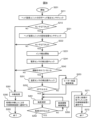
- FIG. 3 is a diagram showing a schematic configuration of the main body control section 7 and printing mechanism section (main body 1 and print head 2) of the inkjet recording apparatus 600 in this embodiment. In particular, various information of the main body control section 7 is shown. It shows the flow.
- reference number 301 is a microprocessing unit (hereinafter referred to as MPU) which is a main component of the main body control section that controls the entire inkjet recording apparatus 600.
- Reference numeral 302 is a bus line, which has a function of transmitting data, control signals, etc. between the devices making up the main body control section.
- the bus line 302 is used to input data, detection signals, etc. necessary for calculations by the MPU 301 from each device, and to transmit data signals, address signals, and control signals to each device.
- Reference number 306 is a read-only memory (ROM) that stores control programs and data necessary for the MPU 301 to operate.
- Reference number 307 is a rewritable memory (RAM) that temporarily stores data required by the MPU 301 while executing a program.
- Reference number 8 is an operation display section for inputting printing contents, setting values, etc., and displaying input data, printing contents, etc.
- the operation display section 8 here uses a touch input type display panel in which transparent touch switches are superimposed on the surface of a liquid crystal display screen.
- the operation section (start button 18 and stop button 19) of the head mounted unit 3 controls the operation operation related to the head mounted unit 3, not the operation display section 8. Use when operating nearby.
- the display section 20 is used when checking the operating status, abnormality messages, etc. regarding the head mounted unit 3, not on the operation display section 8 but near the head mounted unit 3.
- the inkjet recording apparatus 600 can be controlled from the operation display section (start button, stop button, head cleaning button, power button, etc.) of the external control device 100.
- a major feature is that it can be done.
- Another major feature is that it is provided with an information display means (which can be considered as a confirmation means for the operator) that allows confirmation of various operating information of the inkjet recording apparatus 600.
- the external control device 100 allows maintenance and management of the inkjet recording device 600 to be performed remotely.
- the MPU 301 of the main body control unit 7 can be connected to the IoT field server 9 that can wirelessly communicate with the network 14 via the bus line 302. Furthermore, the MPU 301 of the main body control unit 7 may be configured to use an antenna 97 instead of the IoT field server 9 to wirelessly communicate with the network 14 .
- the main body control unit 7 has a function as a "transmission means” or “notification means” that sends and receives various information necessary for maintenance management to and from the external control device 100.
- "head mounting detection information” indicating that the print head 2 is mounted and housed in the head mounting unit 3 is necessary for performing maintenance management of the inkjet recording apparatus 600.
- "ink ejection information” indicating that ink is ejected from the nozzles 21 of the print head 2 is transmitted from the transmission means to the external control device.
- FIG. 6, which will be described later various types of information for performing maintenance management are mutually transmitted.
- the print head 2 of the inkjet recording apparatus 600 includes a nozzle 21 that converts the ink 68A supplied under pressure from the main ink container 31 into particles and discharges the particles.
- the nozzle 21 ejects ink in a columnar shape, and the tips are separated and ejected as ink particles 68B.
- the print head 2 includes a charging electrode 23 surrounding the ink particles 68B, and charges the ink particles 68B according to the print content.
- the print head 2 deflects the flying ink particles 68B charged by the charging electrode 23 according to the amount of charge, and causes them to fly toward a printing target (not shown). Then, printing is performed by the flying ink particles landing on the printing object.
- the deflection electrode 24 of the print head 2 is composed of a ground electrode 24B and a positive electrode 24A.
- the print head 2 includes a gutter 25 that captures ink particles 68B (unused ink) that were not used for printing, and a charge of the ink particles 68B that are slightly charged among the ink particles 68B captured by the gutter 25.
- the charge sensor 48 generates a phase detection signal according to the amount of charge.
- the main body control unit 7 generates an excitation voltage that excites an electrostrictive element (not shown) built into the nozzle 21 in order to provide regularity to the timing at which the ink particles 68B are separated from the ink column ejected from the nozzle 21. It has a circuit 331.
- the main body control section 7 also has a charging signal generation circuit for printing 342 and a charging signal generation circuit for phase search 341, and converts the charging signal in the form of a digital signal outputted from these into a voltage signal in the analog form.
- /A converter 343 and an amplifier circuit 344 that amplifies a voltage signal in the form of an analog signal output from the D/A converter 343 and generates a charging voltage to be applied to the charging electrode 23.
- the inkjet recording apparatus 600 also includes a deflection voltage generation circuit 332 that generates a deflection voltage to be applied to the deflection electrode 24.
- the inkjet recording apparatus 600 also includes an amplifier circuit 353 that amplifies a phase detection signal in the form of an analog signal output from the charge sensor 48, and a phase determination circuit 351 that inputs the amplified phase detection signal to determine whether charging is good or bad.
- An A/D converter 352 is provided that inputs the amplified phase detection signal and performs A/D conversion.
- the MPU 301 of the main body control unit 7 connects a liquid level detection circuit 313 for managing the liquid level of the main ink container 31 via a bus line 302 to a liquid level detecting circuit 313 for controlling the liquid level of the main ink container 31 so that the pressure of the ink supplied to the nozzle 21 is at an appropriate value.
- a pressure detection circuit 312 for detecting whether the viscosity of the ink 68A supplied to the nozzle 21 is an appropriate value for printing
- a viscosity measuring circuit 311 for measuring with the viscosity measuring device 45, the ink 68A, the solvent 69A
- a pump control circuit 314 for controlling the pumps 34 to 37 and 60 to 61 provided in the main body 1 that sucks and pumps air, and opening/closing operations of the solenoid valves 49 to 50 and 53 to 59 in each path.
- the MPU 301 also detects via the bus line 302 that the recovery container 4 is attached to the head attachment unit 3 and that the amount of cleaning liquid in the recovery container 4 has not exceeded a predetermined amount using a magnetic sensor A76 and a magnet A75.
- a collection container sensor detection circuit 322 for detecting using a magnetic sensor B84 and a magnet B86 on the head mounting unit 3 side to detect that the print head 2 is mounted on the head mounting unit 3; It is connected to a head detection circuit 323 and a head attachment unit detection circuit 324 for detecting on the print head 2 side that the print head 2 is attached to the head attachment unit 3 using a magnetic sensor C28 and a magnet C87. It is designed to control each part.
- the main body control section 7 can use a computer.
- the main body control unit 7 includes an MPU 301, a program for the operation of the MPU 301, and memories (306, 307) that store data and information necessary for the operation, and a print head 2 according to instructions from the MPU 301. It can be configured with a head mounting unit 3 and a drive section that operates the components inside the main body 1.
- a detailed explanation of the main body control section 7 will be omitted.
- FIG. 4 is a diagram showing the configuration of the head mounting unit 3 with the collection container 4 removed.
- FIG. 5 is a diagram showing a state in which the recovery container 4 and the print head 2 are installed in the head installation unit 3.
- the head mounting unit 3 includes a cleaning tank 71 to which the print head 2 is mounted during head cleaning, and a head mounting section installed above the cleaning tank 71 for mounting the print head 2 to the head mounting unit 3. 81A, and a head insertion portion 81B which is an entrance for inserting the print head 2 into the cleaning tank 71.
- the cleaning tank 71 is configured so that a collection container 4 for storing the cleaning liquid used in the head cleaning process can be attached to the lower part of the cleaning tank 71 .
- a lid member 83 is assembled in the cleaning block 81.
- the lid member 83 is assembled to the cleaning block 81 via the lid hinge 82.
- This lid member 83 is assembled with a magnet B86 that is used to detect that the print head 2 is attached to the head attachment unit 3.
- a magnetic sensor B84 is assembled in the cleaning block 81 to detect that the magnet B86 has approached within a certain distance when the print head 2 is mounted on the head mounting unit 3. Furthermore, a magnet C87 is attached to the cleaning block 81 and is used to detect that the print head 2 is attached to the head attachment unit 3.
- the cleaning block 81 includes a cleaning nozzle 72 for discharging head cleaning solvent 69A toward the print head 2, and a cleaning nozzle 72 for spraying air to dry the print head 2 wetted with the solvent 69A after head cleaning.
- a supply nozzle 73 having an air discharge port for this purpose is assembled by press-fitting.
- the cleaning nozzle 72 has a liquid ejection hole A section 72A for ejecting the solvent 69A so as to aim at the nozzle 21 assembled on the print head 2, and a liquid ejection hole A section 72A for ejecting the solvent 69A so as to aim at the deflection electrode 24.
- a hole B portion 72B is formed.
- the cleaning nozzle 72 is connected to a channel B section 81E formed in the cleaning block 81.
- the air supply nozzle 73 forms an air discharge hole for jetting air so as to aim between the electrodes of the charging electrode 23 assembled to the print head 2.
- the air supply nozzle 73 is connected to a flow path C portion 81F formed in the cleaning block 81.
- the cleaning block 81 forms a hole 81C that communicates with the inside of the cleaning tank 71 into which the print head 2 is inserted during head cleaning, and a channel A section 81D that is connected to the hole 81C.
- the head mounting unit 3 is equipped with a cleaning tank 71 below the cleaning block 81 for accommodating the print head 2 during head cleaning.
- the cleaning tank 71 has a side wall portion formed to prevent the solvent 69A spouted from the cleaning nozzle 72 from scattering around, and a mounting portion 71A used when the collection container 4 is attached.
- a temperature sensor B80 is installed inside the cleaning tank 71 to detect the ambient temperature of the head mounting unit 3 and use it for various controls.
- a magnetic sensor A76 for detecting that the collection container 4 is attached to the head mounting unit 3 is attached to the cleaning tank 71.
- the collection container 4 configured to be attached to the lower part of the cleaning tank 71 includes a container 77 for storing the cleaning liquid, a partition 78 attached to reduce the splashing of the cleaning liquid when the collection container 4 is carried, It is composed of a float 74 to which a magnet A75 is assembled, and a holder 79 that suppresses the movement of the float 74.
- Such a collection container 4 can be assembled by rotating the collection container 4 by approximately 90 degrees with the collection container 4 attached to the head mounting unit 3, and then attaching the collection container 4 to the mounting portion 71A of the head mounting unit 3 and the collection container 4 that fits there.
- the attachment portion 77A of the container 4 is now in a detached state, and the collection container 4 can be separated from the head mounting unit 3.
- the container 77 has a liquid storage part 77B for storing the cleaning liquid used in the head cleaning process, a mounting part 77A used for fixing to the cleaning tank 71, and an internal thread part 77C for attaching the partition 78.
- the partition 78 has a liquid inlet hole 78A provided to allow the cleaning liquid dripping from the cleaning tank 71 to flow into the container 77, and a liquid inflow hole 78A provided to allow the cleaning liquid to flow out from the container 77 when the collection container 4 is tilted.
- a liquid outflow hole portion 78B is formed.
- a liquid joint 89 connected to the flow path B portion 81E is assembled in the cleaning block 81, and a tube 837A is connected to the liquid joint 89 by a method such as press fitting.
- This tube 837A forms a part of the head cleaning path 837, and is connected to the solvent container 33 in the main body 1 via the tube 837A.
- an air joint 90 connected to the flow path C section 81F is assembled in the cleaning block 81, and a tube 841A is connected to the air joint 90 by a method such as press fitting.
- This tube 841A forms a part of the path (for air supply) 841, and is connected to the pump (for drying) 60 via the tube 841A.
- a suction joint 88 connected to the flow path A portion 81D is assembled in the cleaning block 81, and a tube 843A is connected to the suction joint 88 by a method such as press fitting.
- This tube 841A forms a part of the path (for air suction) 841, and is connected to the pump (for suction) 61 via the tube 841A.
- the head mounted unit 3 is covered with a cover 85 so that the tubes 837A, 841A, and 843A are not exposed to the outside of the head mounted unit 3, and the cover 85 covers the upper part of the washing block 81 and the washing tank. It is fixed so as to sandwich the lower part of 71.
- the cable (for the head mounted unit) 6 is assembled at the bottom of the cover 85 so that it does not protrude outside and interfere with other production equipment. Inside the cable (for the head mounted unit) 6, in addition to the tube 837A, tube 841A, and tube 843A, there are an electric wire 76A connected to the magnetic sensor A76, an electric wire 84A connected to the magnetic sensor B84, and a temperature sensor. Electric wires connected to B80, harnesses (not shown) for operating the start button 18, stop button 19, and display section 20, etc. are passed through, and the head mounting unit 3 and the main body 1 are connected. There is.
- the lid member 83 of the head mounting unit 3 is opened by inserting the print head 2 from which the protective cover 95 has been removed into the head insertion portion 81B.
- the print head 2 is in a state where the nozzle 21, the charging electrode 23, the deflection electrode 24, and the gutter 25 are pushed into a space surrounded by the cleaning tank 71 and the cleaning block 81.
- the head mounting unit 3 is configured such that the inner wall surface of the hole of the head insertion part 81B and the outer wall surface of the head base 94 of the print head 2 fit together so that the position with the print head 2 does not shift from left to right or back and forth. There is. Furthermore, since a portion of the print head 2 comes to rest at a position where it hits the head mounting portion 81A formed in the cleaning block 81, the position of the print head 2 when mounted on the head mounting unit 3 is stabilized.
- the print head 2 of this embodiment is assembled with a magnetic sensor C28 and a temperature sensor A27.
- An electric wire 28A connected to the ceramic sensor C28 and an electric wire 27A connected to the temperature sensor A27 are connected to the main body control section 7 installed in the main body 1 through the inside of the cable (for print head) 5.
- the magnet B86 assembled to the cover member 83 also moves in conjunction with the opening of the cover member 83, and the dotted circle ( As shown surrounded by M2), the magnet B86 and the magnetic sensor B84 approach each other within a certain distance. This allows the head mounting unit 3 to recognize that the print head 2 is now mounted on the head mounting unit 3.
- the print head 2 when the print head 2 is attached to the head attachment unit 3, as shown by the dotted circle (M3), the magnet C87 attached to the cleaning block 81 and the magnet C87 attached to the print head 2 The print head 2 side can also recognize that the sensor C28 has come within a certain distance and the print head 2 is now attached to the head attachment unit 3.
- the magnet A75 assembled to the float 74 of the recovery container 4 and the head attachment unit are cleaned, as shown by the dotted circle (M1).
- the magnetic sensor A76 assembled in the tank 71 approaches within a certain distance.
- the magnetic sensor A76 detects this state, and the main body control section 7 can thereby recognize that the collection container 4 is attached to the head attachment unit 3. By this detection, it is possible to prevent an erroneous operation such as starting the head cleaning process without attaching the collection container 4.
- the cleaning nozzle is provided in the head mounting unit, but it is also possible to adopt a configuration in which a cleaning nozzle with a similar function is provided in a part of the print head 2. An appropriate configuration may be adopted as necessary.
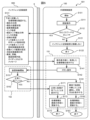
- FIG. 6 is a diagram illustrating the flow of operations and monitoring processing in the inkjet recording system 501.
- FIG. 7 is a diagram illustrating operations and a monitoring screen displayed on the external control device 100.
- FIG. 6 shows the communication status of the inkjet recording device 600, the IoT site server 9, and the external control device 100.
- step S101 of the external control device in FIG. 6 the external control device 100 is operated (remotely controlled) to start processing for starting communication between the external control device 100 and the inkjet recording device 600. When this is completed, the process moves to step S111.
- step S111>> the ID and password necessary for connecting the external control device 100 and the inkjet recording device 600 are input into the external control device 100 . When this is completed, the process moves to step S112.
- step S112 the ID and password input in step S111 are compared and verified with the correct ID and password previously recorded in the IoT field server 9, and whether the input ID and password are correct (YES/NO) is determined. Determine.
- step S121 If it is determined to be correct (YES), a list of device management numbers 122 (see FIG. 7) of the inkjet recording devices 600 registered with that ID is displayed, and when you select the device management number 122 you want to check, The external recording device 100 and the inkjet recording device 600 start communication, and the process moves to step S131. If it is determined that it is not correct (NO), the process moves to step S121.
- step S121 it is displayed on the external recording device 100 that either the ID or the password input in step S111 is incorrect. When this is completed, the process moves to step S22.
- step S131 various information (operation data) of the inkjet recording device 600 is acquired and transmitted to the external control device 100 via the IoT server 9.
- the various information includes, for example, (1) the current date and time (timing of data acquisition) (date and time information); (2) Current device status (print head operation information), (3) Device ambient temperature (temperature information), (4) Ink viscosity (viscosity information), (5) Last ink ejection date and time (date and time information), (6) Remaining amount of ink (remaining ink amount information), (7) Remaining amount of solvent (remaining solvent amount information), (8) Print head installation status of head installation unit (head installation detection information), (9) Recovery container attachment status of the head attachment unit (collection container attachment information); (10) Automatic ink circulation settings (ink circulation setting information), (11) Next automatic circulation date and time (date and time information), (12) Abnormalities/alarms/notifications (message information such as abnormality information
- step S141 various data acquired from the inkjet recording device 600 are displayed on the operation display unit 101 (see FIG. 7) of the external control device 100. When this is completed, the process moves to step S142.
- step S142 necessary button operations are performed based on the information displayed in step S141, and an instruction to start operation is issued to the inkjet recording apparatus 600 for maintenance management. This start of operation is performed on the condition that the print head 2 is mounted and housed in the head mounting unit 3. For this reason, "head attachment detection information" in the claims, which indicates that the print head is attached to the head attachment unit 3, is received from the main body control section 7. When this is completed, the process moves to step S151.
- Step S151 In the inkjet recording apparatus 600, in step S151, the inkjet recording apparatus 600 is operated based on the instruction in step S142. When this is completed, the process moves to step S152.
- step S152 it is determined whether the process in step S151 has been successfully completed (YES/NO). If it is determined that the process has not been completed normally (NO), the process moves to step S161, and if it is determined that the process has completed normally (YES), the process moves to step S171.
- step S161 based on the result of step S152, the operation display unit 101 of the external control device 100 is notified that the operation start process of the inkjet recording apparatus 600 has been interrupted due to an abnormality, and displays a method for dealing with the abnormality. When this is completed, the process moves to step S162.
- step S162 various information including the abnormal message is updated to the latest state. After that, the process moves to step S163, and the process ends in step S163.
- Step S171>> When the process returns to step S152 and the determination is "YES,” in step S171, based on the result of step S152, a message indicating that the operation start process of the inkjet recording apparatus 600 has been successfully completed is displayed on the operation display unit 101 of the external control device 100. Notice. When this is completed, the process moves to step S172.
- step S172 various information is updated to the latest state, and the process moves to step S173, and the process ends in step S173.
- a broken line frame 151 surrounded by a dotted line in FIG. 6 is control related to remote state monitoring and operation in the external control device 100. Furthermore, a broken line frame 152 surrounded by a dotted line is control related to remote operation in the inkjet recording apparatus 600.
- the external control device 100 in FIG. 7 uses a smartphone 16 as an example, but it is also possible to use a tablet 17, a personal computer 15, or the like.
- the external control device 100 in FIG. 7 includes an operation display section 101 using a touch input display panel. By touching the operation display unit 101, the operator can check the status of the inkjet recording apparatus 600 and perform remote control. Furthermore, when the personal computer 15 is used as the external control device 100, the state of the inkjet recording device 600 can be checked and remotely controlled by operating the keyboard, mouse, and touch pad.
- the screen for operating the inkjet recording apparatus 600 shown in FIG. 7 can be displayed by installing dedicated application software on the external control device 100 or by accessing a dedicated web address (URL).
- a dedicated web address can.
- a general tablet or personal computer can be used to start an application for remote control/monitoring of the inkjet recording apparatus 600, display the screen shown in FIG. 7, and perform remote monitoring or remote control.
- the displayed information shown in FIG. 7 can be confirmed by the operator, it can be regarded as confirmation means.
- the current date and time 111 displays the current date and time 111 managed by the main body control unit 7 of the inkjet recording apparatus 600.
- the device ambient temperature 114 displays the temperature detected by the temperature sensor A27 installed in the print head 2 of the inkjet recording device 600. In FIG. 7, the device ambient temperature 114 is displayed, but the temperature detected by the temperature sensor B80 installed in the head mounted unit 3 and the device internal temperature detected by the temperature sensor D38 installed in the main body 1 are It may also be displayed on the control device 100.
- Ink viscosity 115 displays the latest ink viscosity measurement result measured by the viscosity measuring device 45 of the inkjet recording apparatus 600.
- the last ink ejection date and time 112 displays the date and time when the ink particles 68B were last ejected from the nozzle 21 within the confirmable range when the current device status 113 is "inactive or unknown (disconnected)". .
- the ink 68A in the path may dry and stick.
- a message will be displayed in the message display field 131. Display a message that calls for attention.
- the remaining amount of ink 116 indicates the remaining amount of ink 68C in stages based on the detection result of the liquid amount sensor provided in the auxiliary ink container 32 of the inkjet recording device 600.
- the remaining amount of solvent 117 indicates the remaining amount of the solvent 69A in stages based on the detection result of the liquid amount sensor provided in the solvent container 33 of the inkjet recording device 600.
- the remaining amount of the ink 68C or the solvent 69A decreases below a certain value, a message is displayed in the message display field 131 urging caution and replenishment of the ink 68C or the solvent 69A.
- the print head installation status 118 of the head installation unit is displayed with the words "Print head installed, Print head not installed” surrounded by respective frames, and one of them is displayed in dark color. .
- "Print head attached” is displayed in dark color, which indicates that the print head 2 of the inkjet recording apparatus 600 is attached to the head attachment unit 3.
- the collection container mounting state 119 of the head mounting unit is displayed with the characters "with collection container, without collection container” surrounded by respective frames, and one of them is displayed in dark color.
- “Collection container present” is displayed in dark color, which indicates that the collection container 4 of the inkjet recording apparatus 600 is attached to the head mounting unit 3.
- the automatic ink circulation setting 120 it is possible to select either an OFF button or an ON button, and the currently selected button is displayed in a dark color. In FIG. 7, the OFF button is selected, and automatic ink circulation is not performed in this case. If you select the ON button, you can enter any number in "Automatic circulation cycle: x days". For example, if you enter "7" in " ⁇ ", the inkjet recording apparatus 600 automatically automatically displays "(a) Start of ink ejection ⁇ (b) Ink circulation ⁇ (c) Stop ink ⁇ (d) Pause for 7 days.” ” is executed to repeat the operations of steps (a) to (d).
- the inkjet recording apparatus 600 can prevent troubles caused by ink sticking in the path.
- the operations in steps (a) to (d) cause the ink particles 68B to be ejected from the nozzle 21, so the date and time of this operation is reflected in the display of the previous ink ejection date and time 112.
- the automatic ink circulation setting 120 is ON, the next scheduled date and time for (a) ink jetting start is displayed in the above-mentioned (11) next circulation date and time 121.
- the automatic ink circulation setting 120 is turned on, the control when performing the automatic ink circulation setting shown in FIG. 15 is performed.
- abnormality information In the message display field 131, abnormality information, alarm information, confirmation request contents, guidance, etc. are displayed in text format. With this, for example, if an abnormality occurs, it becomes possible to contact the operator with a specific response request.
- the ink ejection start button 141 is pressed when (a) the current device status 113 is displayed as “inactive”, and (b) the print head attachment status 118 of the head attachment unit is displayed as “head attached”. Yes, and (c) the collection container mounting state 119 of the head mounting unit is displayed as "collection container present”.
- the ink ejection start button 141 is operated (pressed), the operation start process shown in FIG. 8 is executed.
- the ink stop button 142 indicates that (a) the current device status 113 is “standby”, and (b) the print head attachment status 118 of the head attachment unit is “head attached”; And (b) it can be executed under the AND condition in which the collection container attachment state 119 of the head mounting unit is displayed as "collection container present".
- the ink stop button 142 is operated (pressed), the operation stop process shown in FIG. 10 is executed.
- the head cleaning start button 143 is activated when (a) the current device status 113 is displayed as "paused", (b) the remaining amount of solvent 117 is at least a certain amount, and (c) the head mounting unit is This can be executed under the AND condition in which the print head mounting state 118 of (d) is displayed as "head mounted” and the collection container mounting state 119 of the head mounting unit (d) is displayed as "collection container present".
- the head cleaning start button 143 is operated (pressed), the head cleaning process shown in FIG. 12 is executed.
- the power OFF button 144 can be executed under the condition that the current device status 113 is displayed as "inactive". When the power OFF button 144 is operated (pressed), the power of the inkjet recording apparatus 600 is turned off.
- the device management number 122 displays a number that identifies the inkjet recording device 600 that is to be remotely controlled by the external control device 100.
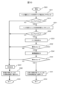
- FIG. 8 is a flowchart of the operation start (ink ejection start) process of the inkjet recording apparatus 600 in this embodiment.
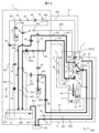
- FIG. 9 shows the flow of ink liquid and air when the inkjet recording apparatus 600 according to the present embodiment has the print head 2 mounted on the head mounting unit 3 and the start of operation (ink ejection) is performed.
- FIG. 3 is a diagram showing fluid paths indicated by thick lines (D1 to D3, D5, D8).
- step S201 the ink ejection start button 141 displayed on the external control device 100 for performing operation start processing is operated (pressed).
- the conditions for the start button to perform the operation start (ink ejection start) process to be enabled are that the inkjet recording apparatus 600 has stopped ejecting ink from the nozzles 21 of the print head 2, and the pump ( Power is not being supplied to ink circulation system components such as the ink supply valve (for supply) 34 and the solenoid valve (for supply) 49, so that they are not in operation.
- the process moves to step S211.
- step S211 it is confirmed whether the magnetic sensor B84 of the head mounting unit 3 is in the "ON” state (detecting the magnet B86 assembled to the lid member 83), and whether the magnetic sensor C28 of the print head 2 is It is checked whether it is in the "ON” state (the magnet C87 assembled in the cleaning block 81 is being detected). When this is completed, the process moves to step S212.
- step S212 if the confirmation result in step S211 is that the magnetic sensor B84 is in the "ON” state and the magnetic sensor C28 is in the "ON” state, then "YES” (the print head 2 is mounted on the head mounting unit 3). The process moves to step S221. If the confirmation result in step S211 is that either the magnetic sensor B84 or the magnetic sensor C28 is in the "OFF” state, it is determined as "NO” (the print head 2 is not mounted on the head mounting unit 3), and The process moves to interruption processing in step S281.
- step S212 The determination result in step S212 is used as "head attachment detection information" in the claims.
- This "head attachment detection information” is transmitted to the external control device 100 by a “head attachment detection notification means” which is a transmission means.
- step S221 it is checked whether the magnetic sensor A76 of the head mounting unit 3 is in the "ON" state (detecting the magnet A75 of the collection container 4). When this is completed, the process moves to step S222.
- Step S222 if the magnetic sensor A76 is in the "ON” state as a result of the confirmation in step S221, it is determined as "YES” (the collection container 4 is attached (attached) to the head attachment unit 3), and The process moves to step S231.
- step S221 if the confirmation result in step S221 is that the magnetic sensor A76 is in the "OFF" state, "NO" is determined in step S222 (the collection container 4 is not attached to the head mounting unit 3, or the collection container 4 is in the OFF state). It is determined that the liquid 70 has accumulated and the float 74 is in a floating state), and the process moves to the interruption process of step S281.
- step S222 The determination result in step S222 is used as "recovery container attachment information" in the claims.
- This "recovery container attachment information” is transmitted to the external control device 100 by a “recovery container attachment notification means” which is a transmission means.
- step S231 the nozzle 21 starts ejecting the ink particles 68B.
- the operation will be explained using FIG. 9.
- the solenoid valve (for supply) 49 is energized to open the flow path, and the switching valve 26 is energized to connect the ink supply path to the nozzle 21.
- the pump (for supply) 34 By operating the pump (for supply) 34, the ink 68A stored in the main ink container 31 of the main body 1 is supplied to the nozzle 21 of the print head 2, as shown by the bold line of arrow D1, and the ink is The particles are discharged from the nozzle 21 as particles 68B.
- the electromagnetic valve (for recovery) 50 is energized to open the flow path, and the pump (for recovery) 35 is operated, as indicated by the thick line of arrow D2. As shown, the ink particles 68B and the air around the print head 2 are sucked from the gutter 25, and are sucked and forced into the main ink container 31 of the main body 1.
- the ink 68A and air flow in a gas-liquid mixture, so the solvent component of the ink 68A dissolves in the air, the air becomes a solvent gas, and flows into the main ink container 31.
- the ink that has flowed into the main ink container 31 is stored in the bottom, and the air that has become a solvent gas is discharged to the outside of the main body 1 as a solvent gas, as shown by the bold line of arrow D3.
- step S241 the ink particles 68B ejected from the nozzle 21 are applied with a voltage by the charging electrode 23, and the charge amount is checked by the charge sensor 48. When this is completed, the process moves to step S242.
- step S242 it is confirmed whether the amount of charge of the ink particles 68B measured by the charge sensor 48 does not exceed a predetermined threshold value, and if it does not exceed the threshold value, the answer is "YES" (the ink particles 68B ejected from the nozzle 21 It is determined that the ink particles 68B have been collected from the gutter 25 and there is no abnormality in the voltage application to the ink particles 68B by the charging electrode 23, and the process moves to step S251.
- step S281 the ink particles 68B ejected from the nozzle 21 have not been collected from the gutter 25, or there is an abnormality in the voltage application to the ink particles 68B by the charging electrode 23. ), and the process moves to the interruption process of step S281.
- step S241 The determination result in step S241 is used as "charging abnormality information" in the claims.
- This "charging abnormality information” is transmitted to the external control device 100 by a “charging abnormality notification means" which is a transmission means.
- step S251 the detection result of the temperature sensor A27 provided in the print head 2 is confirmed. When this is completed, the process moves to step S252.
- step S252 the temperature of temperature sensor A7 is determined. If the detection result of the temperature sensor A27 is less than 25°C, it is determined as "NO" (the generation of the ink particles 68B may become unstable due to the low ambient temperature of the print head 2), and the process proceeds to step S253. to move to. On the other hand, if the detection result of the temperature sensor A27 is 25° C. or higher, it is determined as “YES” and the process moves to step S261.
- step S252 The determination result in step S252 is used as "temperature abnormality information".
- This "charging abnormality information” is transmitted to the external control device 100 by a “charging abnormality notification means" which is a transmission means.
- step S253 the ink supplied to the nozzles 21 is heated using the heater control circuit 317 and the heater 29 provided in the print head 2.
- the heater 29 continues to control the heating of the ink until the temperature detected by the temperature sensor C30 rises to a predetermined temperature.
- the time required for heating control of the heater 29 becomes longer as the detection result of the temperature sensor A27 is lower, and becomes shorter as the detection result of the temperature sensor A27 is higher. If the detection result of the temperature sensor C30 reaches a predetermined temperature, the process moves to step S261.
- the heater 29 continues to control the heating of the ink in the steps after step S261 as long as the detection result of the temperature sensor A27 is 25° C. or lower.
- the condition for heating control by the heater 29 is that the detection result of the temperature sensor A27 is less than 25°C, but the conditions for implementing heating control may vary depending on the type of ink and the performance of the heater 29 and nozzle 21. shall be different.
- step S261 the viscosity measuring device 45 provided in the main body 1 is used to measure the viscosity of the ink 68A. The operation will be explained using FIG. 9.
- the electromagnetic valve (for viscosity measurement) 57 is energized to open the flow path, and the pump (for circulation) 36 is operated, as indicated by the thick line of arrow D8.
- the ink 68A contained in the main ink container 31 of the main body 1 passes through the viscosity measuring device 45, the electromagnetic valve (for viscosity measurement) 57, and the pump (for circulation) 36, and returns to the main ink container 31.
- the ink 68A is circulated.
- the ink 68A is passed through the viscosity measuring device 45 to measure the ink viscosity. Then, the ink density is calculated based on the relationship between temperature and viscosity for each type of ink recorded by the main body control section 7. When this is completed, the process moves to step S262.
- step S262 it is determined whether the ink viscosity (converted to density) calculated in step S261 and converted to density is higher than a predetermined threshold value. If it is lower than the threshold, it is determined “NO” (because the viscosity of the ink 68A in the main ink container 31 is low, the generation of ink particles 68B may become unstable), and the process moves to step S263. do. On the other hand, if it is higher than the threshold, the determination is "YES" and the process moves to step S271.
- step S262 The determination result of "YES" in step S262 becomes “viscosity adjustment completion information" in the claims.
- This "viscosity adjustment completion information” is transmitted to the external control device 100 by a “viscosity adjustment notification means" which is a transmission means.
- step S263>> concentration control of the ink 68A is performed. The detailed operation will be explained using FIG. 9.
- the solvent component in the ink 68A is discharged outside the machine as a solvent gas, as shown by the bold line D3.
- the ratio of the solvent component decreases, and the concentration of the ink 68A becomes high.
- the amount of ink 68A decreases as the solvent component is discharged to the outside of the machine, so the corresponding amount is replenished from the ink 68C of the auxiliary ink container 32.
- the solenoid valve (for replenishment) 54 is energized to open the flow path, and the switching valve 26 is energized to connect the ink replenishment path to the nozzle 21.
- the pump (for supply) 34 By operating the pump (for supply) 34, the ink 68C stored in the auxiliary ink container 32 of the main body 1 merges with the arrow D1 and flows into the nozzle 21 of the print head 2, as shown by the thick line of the arrow D8.
- the ink is supplied to the main ink container 31 via ink recovery paths 811 to 812 shown by arrow D2.
- step S271 the message display column 131 of the external control device 100 displays that the process of starting operation (starting ink jetting) of the inkjet recording device 600 has been successfully completed.
- the notification means which is the transmission means of the main body control section 7, transmits the above-mentioned various operating information to the external control device. This allows the external control device 100 to check various operating information and enables remote monitoring. Then, the display of the current device status 113 is switched from "dormant" to "standby". When this is completed, the process moves to step S272.
- the inkjet recording apparatus 600 is in a state in which power is supplied to ink circulation system components such as the pump (for supply) 34 and the solenoid valve (for supply) 49, and ink particles 68B are ejected from the nozzles 21.
- step S281 the operation start (ink ejection start) process is interrupted based on the determination result of step S212, step S222, or step S242.
- step S282 power supply to ink circulation system components such as the pump (for supply) 34 and the solenoid valve (for supply) 49 is stopped. When this is completed, the process moves to step S282.
- the message display column 131 of the external control device 100 displays that the operation start (ink ejection start) process of the inkjet recording device 600 has been interrupted.
- the notification means which is the transmission means of the main body control section 7, transmits the above-mentioned various operating information to the external control device. This allows the external control device 100 to check various operating information and enables remote monitoring.
- the message display field 131 displays the reason for suspending the process and a countermeasure. When this is completed, the process moves to step S283.
- step S283 various information (operation data) is updated to the latest state, and the process ends.
- the inkjet recording apparatus 600 is in a standby state in which power is not supplied to the ink circulation system components such as the pump (for supply) 34 and the solenoid valve (for supply) 49, so that the inkjet recording apparatus 600 is not in operation.
- FIG. 10 is a flowchart of the process of stopping the operation (stopping ink ejection) of the inkjet recording apparatus 600 in this embodiment.
- FIG. 11 shows an inkjet recording apparatus 600 according to this embodiment in which the print head 2 is attached to the head attachment unit 3, and the ink, solvent, and air are being cleaned while nozzle cleaning and circulation path cleaning are being performed. It is a diagram showing the flows (E1 to E7) with thick lines.
- step S301 the ink stop button 142 displayed on the external control device 100 for performing an operation stop process is operated (pressed).
- the inkjet recording apparatus 600 must have power supply to the ink circulation system parts such as the pump (for supply) 34 and the solenoid valve (for supply) 49. is being supplied, and ink particles 68B are being ejected from the nozzle 21.
- the process moves to step S311.
- steps S311, S312, S321, and S322 are the same operations as steps S211, S212, S221, and S222 described in FIG. 8. Therefore, description of steps S311, S312, S321, and S322 will be omitted. When these are completed, the process moves to step S331.
- Step S331 is an ink jetting stop step, in which the jetting of ink particles 68B from the nozzles 21 of the print head 2 is stopped.
- the ink supply path paths 801 to 804 of the inkjet recording device 600
- the flow path is closed by stopping the power supply to the solenoid valve (for supply) 49 and the switching valve 26 to make them in a non-energized state.
- the ink 68A is prevented from being supplied from the main ink container 31 to the nozzle 21.
- the process moves to step S332.
- step S332 if the process in step S331 is successfully completed, the determination is "YES” and the process moves to step S341. On the other hand, if some abnormality is detected and the process cannot be completed normally, the determination is "NO” and the process moves to the interruption process of step S361.
- step S341 the circulation path is cleaned, and the solvent 69A is supplied to the nozzle 21 of the print head 2 to clean the nozzle 21 from inside. The operation will be explained using FIG. 11.
- the electromagnetic valve (for nozzle cleaning) 55 is energized to open the flow path, and the pump (for solvent) 37 is operated, as indicated by the thick line of arrow E1.
- the solvent 69A contained in the solvent container 33 of the main body 1 is supplied to the print head 2 and discharged from the nozzle 21.
- the solenoid valve (for recovery) 50 is energized to open the flow path, and the pump (for recovery) 35 is operated, as shown by the thick line of arrow E1.
- the solvent 69A discharged from the nozzle 21 is captured by the gutter 25 and collected into the main ink container 31.
- the solenoid valve (for circulation) 59 is energized to open the flow path. Then, by operating the pump (for circulation) 36, at least a portion of the solvent 69A supplied to the nozzle 21 is sucked into the pump (for circulation) 36, and the main ink flows in the flow shown by the bold line of arrow E3. They are collected into a container 31. In this way, the inkjet recording apparatus 600 can use the solvent 69A to clean the nozzles 21, the ink paths (for collection) 811 to 812, and the paths (for ink circulation) 821 to 822.
- the solenoid valve (for supply) 49 and the solenoid valve (for main body circulation) 58 are closed.
- the pump (for supply) 34 and pump (for collection) 35 the ink stored in the main ink container 31 of the main body 1 is discharged, as shown by the thick line of arrow E7. 68A is circulated.
- the electromagnetic valve (for viscosity measurement) 57 is energized to open the flow path, and the pump (for circulation) 36 is operated, so that the main body
- the ink 68A contained in the main ink container 31 of 1 is supplied to the viscosity measuring device 45, and the viscosity of the ink 68A is measured using the viscosity measuring device 45 at the timing of ink circulation within the main body 1. Keep track of the condition of the ink 68A when using it. When this is completed, the process moves to step S342.
- step S342 if the process in step S341 is successfully completed, the determination is "YES” and the process moves to step S351. On the other hand, if some abnormality is detected and the process cannot be completed normally, the determination is "NO” and the process moves to the interruption process of step S361.
- step S351 the message display column 131 of the external control device 100 displays that the operation stoppage (ink ejection stoppage) process of the inkjet recording apparatus 600 has been successfully completed.
- the notification means which is the transmission means of the main body control section 7, transmits the above-mentioned various operating information to the external control device. This allows the external control device 100 to check various operating information and enables remote monitoring. Then, the display of the current device status 113 is switched from "standby" to "dormant". When this is completed, the process moves to step S352.
- Step S352>> various information is updated to the latest state, and the process ends.
- the ink circulation system parts such as the pump (for supply) 34 and the solenoid valve (for supply) 49, etc. Stand by with the power supply stopped.
- step S361 the operation stop (ink ejection stop) process is interrupted based on the determination result of step S312, step S322, step S332, or step S342.
- step S361 power supply to ink circulation system components such as the pump (for supply) 34 and the solenoid valve (for supply) 49 is stopped. When this is completed, the process moves to step S352.
- step S362 the message display field 131 of the external control device 100 displays that the operation start (ink ejection start) process of the inkjet recording device 600 has been interrupted. In addition, the message display field 131 displays the reason for suspending the process and a countermeasure.
- the notification means which is the transmission means of the main body control section 7, transmits the above-mentioned various operating information to the external control device. This allows the external control device 100 to check various operating information and enables remote monitoring. When this is completed, the process moves to step S352.
- Step S363>> various information (operation data) is updated to the latest state, and the process ends.
- the inkjet recording apparatus 600 is in a standby state in which power is not supplied to the ink circulation system components such as the pump (for supply) 34 and the solenoid valve (for supply) 49, so that the inkjet recording apparatus 600 is not in operation.
- FIG. 12 is a flowchart of the head cleaning process.
- FIG. 13 shows the flow of liquid (cleaning liquid) and gas (air or solvent gas) throughout the apparatus when head cleaning processing is being performed with the print head 2 attached to the head mounting unit 3.
- FIG. 3 is a fluid path diagram showing A1 to A8) with thick lines.
- FIG. 14 is a diagram showing a state in which a large amount of cleaning liquid is contained in the collection container in the head mounted unit.
- step S401 the head cleaning start button 143 displayed on the external control device 100 for performing head cleaning processing is operated (pressed).
- the conditions for the start button to perform the head cleaning process to be enabled are that the inkjet recording device 600 has stopped ejecting ink from the nozzles 21 of the print head 2, and the pump (for supply) 34 and solenoid valve (for supply) have stopped. ) 49 and other ink circulation system components are not being supplied with power and are not operating. When this is completed, the process moves to step S411.
- steps S411, S412, S421, and S422 are the same operations as steps S211, S212, S221, and S222 described in FIG. 8. Therefore, description of steps S411, S412, S421, and S422 will be omitted. When these are completed, the process moves to step S431.
- step S431 a liquid amount sensor (not shown) is used to confirm whether the amount of the solvent 69A in the solvent container 33 is sufficient for head cleaning. When this is completed, the process moves to step S432.
- step S432 The determination result in step S432 is used as "liquid amount abnormality information" in the claims.
- This "liquid volume abnormality information" is transmitted to the external control device 100 by a “liquid volume abnormality notification means" which is a transmission means.
- step S441 the solvent 69A is supplied to the cleaning nozzle 72 of the head mounting unit 3 to clean the print head 2. The operation will be explained using FIG. 13.
- the inkjet recording apparatus 600 is in a state where the print head 2 is mounted on the head mounting unit 3 for print head cleaning.
- the solenoid valve (for head cleaning) 56 is energized to open the flow path, and the pump (for solvent) 37 is operated, as indicated by the thick line of arrow A1.
- a solvent which is a cleaning liquid, is supplied to the head mounting unit 3. That is, the solvent 69A contained in the solvent container 33 of the main body 1 can be supplied to the cleaning nozzle 72 assembled in the cleaning tank 71 of the head mounting unit 3.
- the cleaning nozzle 72 jets (discharges) this solvent 69A toward the print head to clean the print head 2.
- the solvent 69A supplied to the cleaning nozzle 72 is directed in the direction of arrow A2 (the direction in which the solvent 69A is spouted from the liquid discharge hole A section 72A toward the nozzle 21) and the arrow A3 (from the liquid discharge hole B section 72B).
- the solvent 69A is ejected in the direction indicated by (direction in which the solvent 69A is ejected aiming at the deflection electrode 24), and the solvent 69A is sprayed onto components such as the nozzle 21 and the deflection electrode 24 assembled to the print head 2, thereby performing inkjet recording. It is possible to clean stains caused by the ink 68A that adheres during operation or maintenance of the device 600.
- the solvent 69A that has cleaned the nozzle 21, deflection electrode 24, and other components assembled in the print head 2 drips downward due to gravity.
- the charging electrode 23 and the gutter 25 disposed below the deflection electrode 24 can be cleaned with the solvent 69A.
- the solvent 69A that has cleaned the components such as the nozzle 21, charging electrode 23, deflection electrode 24, and gutter 25 arranged on the print head 2 drips down in the direction shown by arrow A4.
- the liquid flows into a recovery container 4 installed at the lower part of the head mounting unit 3, and is stored as a liquid 70A in a liquid storage section 77B.
- the solenoid valve (for circulation) 59 is energized to open the flow path, and the pump (for circulation) 36 is operated, as shown by the thick line of arrow A5.
- a part of the solvent 69A that has hit the nozzle 21 is sucked out from the nozzle 21 and collected into the main ink container 31 of the main body 1. In this way, in the head cleaning process, the inside of the nozzle 21 and the ink circulation paths 821 to 822 can also be cleaned with the solvent 69A.
- the electromagnetic valve (for recovery) 50 is energized to open the flow path and the pump (for recovery) 35 is operated, as shown by the thick line of arrow A6.
- a part of the solvent 69A that has hit the gutter 25 is sucked out from the gutter 25 and collected into the main ink container 31 of the main body 1.
- the inside of the gutter 25 and the ink recovery paths 811 to 812 can also be cleaned with the solvent 69A.
- the nozzle 21 and the gutter 25 suck the surrounding air together with the solvent 69A.
- the air sucked at this time becomes solvent vapor as the vaporized solvent 69A is dissolved in the ink circulation paths 821 to 822 and the ink recovery paths 811 to 812.
- this solvent vapor is discharged via a path 814 to an exhaust duct connection 62 that communicates with the outside of the main body 1.
- the inkjet recording apparatus 600 is configured such that the solvent vapor discharged from the main ink container 31 and the solvent vapor discharged from the head mounting unit 3 are collectively discharged from the exhaust duct connection part 62.
- the exhaust duct connection section 62 is located at a location away from the operation display section 8 of the main body 1, and is assembled, for example, on the back or bottom surface of the main body 1. After cleaning the print head 2, the process moves to step S442.
- step S442 if the process in step S441 is successfully completed, the determination is "YES” and the process moves to step S451. On the other hand, if some abnormality is detected and the process cannot be completed normally, the determination is "NO” and the process moves to the interruption process of step S481.
- the abnormalities detected in step S442 there is a case where the amount of liquid in the recovery container 4 increases due to repeated execution of the head cleaning process, and this state will be explained using FIG. 14.
- the main body control unit 7 can detect (judge) that the amount of cleaning liquid 70 that can be further accommodated in the collection container 4 is small and that it is almost full.
- the main body control section 7 displays a warning on the operation display section 8 or the display section 20 of the head mounted unit 3, or notifies the external control device 100 of the warning.
- the operation display section 8, the display section 20 of the head mounted unit 3, and the external control device 100 display a warning and, for example, a message indicating that the collection container 4 should be removed and the liquid 70 inside should be drained as a countermeasure. Also good.
- the operator can remove the collection container 4 and drain the liquid 70 inside the collection container 4, as shown in FIG. Then, the empty recovery container 4 is attached to the lower part of the cleaning tank 71 again. Since the magnetic sensor A76 of the liquid level detection device is installed outside the collection container 3, the collection container 4 can be easily removed and attached.
- the float 74 When the collection container 4 is attached, the float 74 is in a position where it can be detected by the magnetic sensor A76, so the magnetic sensor A76 starts outputting a liquid level detection signal.
- the main body control section 7 can receive the liquid level detection signal from the magnetic sensor A76 and determine that the collection container 4 has been attached. Based on this determination, the main body control section 7 erases the warning display displayed on the operation display section 8. Alternatively, control can be performed to display that the head mounting unit 3 is in an operable (cleanable) state, or to cancel the prohibition state of the head cleaning operation and permit head cleaning.
- step S451 a voltage is applied to the deflection electrode 24, and it is checked whether the charge sensor 48 detects the voltage. When this is completed, the process moves to step S452.
- step S461 a message indicating that the head cleaning process of the inkjet recording apparatus 600 has been successfully completed is displayed in the message display column 131 of the external control device 100.
- the notification means which is the transmission means of the main body control section 7, transmits the above-mentioned various operating information to the external control device. This allows the external control device 100 to check various operating information and enables remote monitoring. When this is completed, the process moves to step S462.
- various information is updated to the latest state, and the process ends.
- the inkjet recording apparatus 600 stands by in a state where power supply to ink circulation system components such as the pump (for supply) 34 and the solenoid valve (for supply) 49 is stopped.
- step S471 the message display column 131 of the external control device 100 displays information indicating that there is a possibility that dirt may remain on the print head 2 and a countermeasure such as executing the head cleaning process again. When this is completed, the process moves to step S472.
- the notification means which is the transmission means of the main body control section 7, transmits the above-mentioned various operating information to the external control device. This allows the external control device 100 to check various operating information and enables remote monitoring.
- the inkjet recording apparatus 600 stands by in a state where power supply to ink circulation system components such as the pump (for supply) 34 and the solenoid valve (for supply) 49 is stopped.
- step S481 the head cleaning process is interrupted based on the determination result of step S412, step S422, step S432, or step S442.
- step S482 power supply to ink circulation system components such as the pump (for supply) 34 and the solenoid valve (for supply) 49 is stopped. When this is completed, the process moves to step S482.
- step S482 a message indicating that the head cleaning process of the inkjet recording apparatus 600 has been interrupted is displayed in the message display field 131 of the external control device 100.
- the message display field 131 displays the reason for suspending the process and a countermeasure.
- step S483 various information (operation data) is updated to the latest state, and the process ends.
- the notification means which is the transmission means of the main body control section 7, transmits the above-mentioned various operating information to the external control device. This allows the external control device 100 to check various operating information and enables remote monitoring.
- the inkjet recording apparatus 600 is in a standby state in which power is not supplied to the ink circulation system components such as the pump (for supply) 34 and the solenoid valve (for supply) 49, so that the inkjet recording apparatus 600 is not in operation.
- FIG. 15 is a flowchart of control when automatic ink circulation setting is performed.
- the print head 2 is attached to the head mounting unit 3, and the thick lines indicate the liquid flow and gas flow (D1 to D8) when ink is being circulated between the main body and the print head.
- FIG. 16 the print head 2 is attached to the head mounting unit 3, and the thick lines indicate the liquid flow and gas flow (D1 to D8) when ink is being circulated between the main body and the print head.
- the process flow of FIG. 15 is an ink circulation cycle in which ink is ejected from the nozzles at set intervals to circulate the ink to each path, and then the ink ejection from the nozzles is stopped and waited.
- This is the "ink circulation cycle means" referred to in the claims that performs repeated operations.
- step S501 the ON button of the automatic ink circulation setting 120 displayed on the external control device 100 is operated (pressed).
- the conditions for the ON button of the automatic ink circulation setting 120 to be enabled are that the inkjet recording device 600 has stopped ejecting ink from the nozzles 21 of the print head 2, and the pump (for supply) 34 and solenoid valve (for supply) have stopped. ) 49 and other ink circulation system components are not being supplied with power and are not operating.
- the process moves to step S511.
- steps S511, S512, S521, and S522 are the same operations as steps S211, S212, S221, and S222 described in FIG. 8. Therefore, description of steps S511, S512, S521, and S522 will be omitted. When these are completed, the process moves to step S531.
- step S531 first, the same operation as the start of ink ejection in step S231 described with reference to FIG. 9 is performed. Then, the ink particles 68B ejected from the nozzle 21 are applied with a voltage by the charging electrode 23, and the charge amount is checked by the charge sensor 48. When this is completed, the process moves to step S532.
- step S532 if the process in step S531 is completed normally, it is determined as "YES” (no abnormality) and the process moves to step S541. On the other hand, if some abnormality is detected and the process cannot be completed normally, the determination is "NO” and the process moves to ink jetting interruption processing in step S580.
- step S541 ink circulation processing within the path is performed. This ink circulation process will be explained using FIG. 16.
- step S541 "circulation cycle implementation information" referred to in the claims, which indicates the implementation status of the ink circulation cycle, is generated, and this "circulation cycle implementation information" is transmitted by "circulation cycle implementation status notification means”. ” is transmitted to the external control device 100.
- the ink supply paths 801 to 804 shown by arrow D1 the ink recovery paths 811 to 812 shown by arrow D2, and the solvent gas discharge path 814 shown by arrow D3 are the same as in FIG. Since the operation is as follows, the explanation will be omitted. In FIG. 16, parts different from those in FIG. 9 will be explained.
- the solvent component in the ink 68A is discharged outside the machine as a solvent gas, so as the operating time increases, the ratio of the solvent component in the ink 68A decreases. , the density of the ink 68A may become high. Conversely, if the operating time is short, the concentration of ink may become low due to the solvent 69A flowing into the main ink container 31 during circulation system cleaning processing or the like.
- the solenoid valve (for viscosity measurement) 57 is energized to open the flow path, and the pump (for circulation) 36 is operated, as indicated by the thick line of arrow D5.
- the ink 68A in the main ink container 31 is sent to the viscosity measuring device 45, and the viscosity (converted to concentration) of the ink 68A is periodically measured.
- This measured detected value of viscosity is input to the main body control section 7.
- the main body control unit 7 replenishes the ink 68C in the auxiliary ink container 32 to the main ink container 31 when the concentration of the ink 68A is low, and when the concentration of the ink 68A is high, it replenishes the ink 68C as indicated by the thick line of arrow D7.
- the main ink container 31 is controlled to be supplied with the solvent 69A in the solvent container 33. In this way, in the inkjet recording apparatus 600, the viscosity of the ink 68A is controlled to fall within the range of management values.
- the solenoid valve (for circulation) 59 is energized to circulate the flow path.
- the pump and operating the pump (for circulation) 36 By opening the pump and operating the pump (for circulation) 36, at least a portion of the ink 68A supplied to the nozzle 21 is sucked into the pump (for circulation) 36, and the main flow is shown by the thick line of arrow D2.
- the ink 68A is circulated back to the ink container 31.
- the solenoid valve (for body circulation) 58 is energized to open the flow path and the pump (for circulation) 36 is operated, as shown by the thick line of arrow D6.
- the ink 68A can also be circulated through the path (for body circulation) 808.
- the inkjet recording apparatus 600 circulates the ink through most of the paths, thereby preventing the ink in the paths from drying and sticking.
- a voltage is applied to the ink particles 68B ejected from the nozzle 21 by the charging electrode 23, and the amount of charge is confirmed by the charge sensor 48, so that the ink particles 68B are discharged from the nozzle 21 during the ink circulation process.
- Step S542 if the ink circulation process in step S541 is completed normally, it is determined as "YES” (no abnormality) and the process moves to step S551. On the other hand, if an abnormality related to the thermal circulation is detected and the process cannot be completed normally, the determination is "NO" and the process moves to the ink jetting interruption process of step S580.
- step S542 The determination result in step S542 is used as "circulation cycle abnormality information" in the claims.
- This "circulation cycle abnormality information” is transmitted to the external control device 100 by a “circulation cycle abnormality notification means" which is a transmission means.
- step S551 the same operation as the ink ejection stop in step S331 described with reference to FIG. 10 is performed. When these are completed, the process moves to step S552.
- step S552 the same operation as the circulation route cleaning in step S341 described in FIG. 10 is performed. When this is completed, the process moves to step S553.
- step S553 if the process in step S552 is successfully completed, the determination is "YES” and the process moves to standby in step S561. On the other hand, if some abnormality is detected and the process cannot be completed normally, the determination is "NO” and the process moves to the interruption process of step S591.
- step S561 the inkjet recording apparatus 600 waits for the period input in the circle of "Automatic circulation cycle: x days" in the automatic ink circulation setting 120 under the condition that the current device status 113 is "inactive". do. When this is completed, the process moves to step S562.
- step S562 it is checked whether the OFF button of the automatic ink circulation setting 120 was operated (pressed) using the external control device 100 during the standby period of step S561. If the OFF button has been operated (pressed), the determination is "YES” and the process moves to step S571. On the other hand, if the OFF button has not been operated (pressed), the determination is "NO” and the process moves to step S563.
- non-ejection time information referred to in the claims can also be transmitted to the external control device 100 by a "non-ejection time notification means" which is a transmission means.
- various information is updated to the latest state, and the process ends.
- the inkjet recording apparatus 600 stands by in a state where power supply to ink circulation system components such as the pump (for supply) 34 and the solenoid valve (for supply) 49 is stopped.
- step S580 is an ink ejection interruption step based on the determination result of step S532 or step S542, and a process of stopping the ejection of ink particles 68B from the nozzles 21 of the print head 2 is performed.
- the ink supply path paths 801 to 804 of the inkjet recording device 600
- the flow path is closed by stopping the power supply to the solenoid valve (for supply) 49 and the switching valve 26 to make them in a non-energized state.
- the ink 68A is prevented from being supplied from the main ink container 31 to the nozzle 21.
- the process moves to step S581.
- step S581 the same operation as the head cleaning in step S441 described with reference to FIG. 12 is performed. When this is completed, the process moves to step S582.
- step S582 the same operation as the start of ink ejection in step S531 described above is performed. When this is completed, the process moves to step S583.
- step S583 it is confirmed whether the abnormality detected in step S532 or step S542 has been repaired using the same method as in step S532. If it can be determined that it has been repaired (no abnormality), the determination is "YES” and the process moves to step S541. On the other hand, if any abnormality is detected, the determination is "NO" and the process moves to the interruption process of step S591.
- step S591 the automatic ink circulation setting is canceled based on the determination result in step S512, step S522, step S583, or step S553.
- step S592 power supply to ink circulation system components such as the pump (for supply) 34 and the solenoid valve (for supply) 49 is stopped. When this is completed, the process moves to step S592.
- step S592 the message display field 131 of the external control device 100 displays that the automatic ink circulation setting 120 of the inkjet recording device 600 has been canceled. In addition, the message display field 131 displays the reason for suspending the process and a countermeasure.
- the notification means which is the transmission means of the main body control section 7, transmits the above-mentioned various operating information to the external control device. This allows the external control device 100 to check various operating information and enables remote monitoring. When this is completed, the process moves to step S593.
- the inkjet recording apparatus 600 is in a standby state in which power is not supplied to the ink circulation system components such as the pump (for supply) 34 and the solenoid valve (for supply) 49, so that the inkjet recording apparatus 600 is not in operation.
- the state of the inkjet recording device 600 can be checked remotely, and if there is an abnormality, the operator is contacted to request a response. This makes it possible to prevent the inkjet recording apparatus from being left in an abnormal state.
- the external control device 100 is used to perform operation start processing (ink ejection start) and operation stop processing ( Routine tasks such as stopping ink jetting can be performed remotely.
- settings such as head cleaning processing and automatic ink circulation processing can be performed using the external control device 100. Routine maintenance tasks can be performed remotely.
- the operation information can be checked remotely, so that if there is an abnormality, the operator will be contacted to request a response. This can prevent the inkjet recording apparatus from being left in an abnormal state.
- an inkjet recording system 502 according to a second embodiment of the present invention will be described. Also in the second embodiment, the same configuration as in FIGS. 1 to 16 described in the first embodiment can be adopted.
- FIG. 17 shows a perspective view showing how the inkjet recording apparatus and inkjet recording system according to the second embodiment are used. Since the explanation regarding FIGS. 1 to 16 has already been explained, the explanation thereof will be omitted. Then, using FIG. 17, mainly the differences from the first embodiment will be explained.
- FIG. 17 is a perspective view showing how the inkjet recording apparatus according to the second embodiment of the present invention is used.
- the inkjet recording system 503 includes an inkjet recording device 600C or 600D, and an external control device 100 that performs wireless communication with the inkjet recording device 600 via a network 201.
- the inkjet recording devices 600C and 600D are equipped with an antenna 97 for connecting to the network 201.
- the inkjet recording apparatuses 600C and 600D are configured to be connected to the external control device 100 using the network 201.
- LAN Local Area Network
- WAN Wide Area Network
- Internet Internet
- mobile phone line network a combination of these networks
- the operation start (ink ejection start) process described in FIG. 8 and the operation stop (ink ejection stop) process described in FIG. 10 are performed similarly to the inkjet recording system 501.
- the head cleaning process described in FIG. 12, and the control when performing the automatic ink circulation setting described in FIG. 15 can be performed.
- the inkjet recording device 600 by providing the inkjet recording device 600 with a wireless communication function, the state of the inkjet recording device 600 can be checked remotely using the external control device 100 without a wired connection.
- the inkjet recording device 600 is provided with a wireless communication function, and the print head 2 of the inkjet recording device 600 is mounted on the head mounting unit 3, so that the external control device 100 can be used. It is possible to remotely perform daily tasks such as operation start processing (starting ink jetting) and operation stop processing (stopping ink jetting) without a wired connection.
- the inkjet recording device 600 is provided with a wireless communication function, and the print head 2 of the inkjet recording device 600 is mounted on the head mounting unit 3, so that the external control device 100 can be used. Routine maintenance tasks such as head cleaning and automatic ink circulation settings can be performed remotely without a wired connection.
- an inkjet recording system 503 according to a third embodiment of the present invention will be described. Also in the third embodiment, the same configuration as in FIGS. 1 to 17 described in the first embodiment and the second embodiment can be adopted.
- FIG. 18 is a perspective view showing how the inkjet recording apparatus and inkjet recording system according to the third embodiment are used. Since the explanation regarding FIGS. 1 to 17 has already been explained, the explanation thereof will be omitted. Then, using FIG. 18, mainly the parts different from the first embodiment and the second embodiment will be explained.
- FIG. 18 is a perspective view showing how the inkjet recording apparatus according to this embodiment is used.
- the inkjet recording system 503 includes an inkjet recording device 600E or 600F, a cloud server 209 that wirelessly communicates with the inkjet recording device 600 via a network 214A, and an external control device 100 that wirelessly communicates with the cloud server 209 via a network 214B. It is made up of.
- the inkjet recording devices 600E and 600F are equipped with an antenna 97 for connecting to the network 214A.
- the inkjet recording devices 600E and 600F are configured to be connected to the external control device 100 using the networks 214A and 214B and the cloud server 209.
- the inkjet recording devices 600E and 600F are connected to a first network 214A, and the first network 214A is further connected to a cloud server 209. Further, the cloud server 209 is connected to a second network 214B, and the second network 214B is further connected to the external control device 100.
- the inkjet recording devices 600E and 600F are connected to the cloud server 209 via the first network 214A, and the external control device 100 is connected via the second network 214B.
- the external control device 100 is connected via the second network 214B.
- networks 214A and 214B "LAN (Local Area Network)”, “WAN (Wide Area Network)”, “Internet”, “Mobile phone line network”, and a combination of these networks can be used. .
- LAN Local Area Network
- WAN Wide Area Network
- Internet Internet
- Mobile phone line network and a combination of these networks can be used.
- FIG. 19 The flow of the state monitoring operation of the inkjet recording system 503 according to this embodiment will be explained using FIG. 19.
- reference number 600 is an inkjet recording device
- reference number 209 is a cloud server
- reference number 100 is an external control device.
- step S601 the cloud server 209 attempts to periodically check the status of the inkjet recording apparatus 600. Once the status is confirmed, the process moves to step S602.
- Step S612 if the connection between the cloud server 209 and the inkjet printing apparatus 600 fails, various information about the inkjet printing apparatus 600 recorded in the cloud server 209 is not updated. Then, after a certain period of time has elapsed, the process of step S601 is executed again.
- step S622 the inkjet recording apparatus 600 checks various information (operation data) as described in step S131 of FIG. results). When this is completed, the process moves to step S623.
- step S623 various information about the inkjet recording apparatus 600 recorded on the cloud server 209 is updated to the latest information. Then, after a certain period of time has elapsed, the process of step S601 is executed again to maintain the various information of the inkjet printing apparatus 600 recorded in the cloud server 209 in a new state.
- step S631 of the external control device 100 the external control device 100 is operated to start a communication connection process between the external control device 100 and the inkjet recording device 600.
- External control device 100 is connected to cloud server 209 via network 214B. When this is completed, the process moves to step S632.
- Step S632 the ID and password necessary for connecting the external control device 100 and the inkjet recording device 600 are input into the external control device 100. When this is completed, the process moves to step S633.
- step S633 the ID and password input in step S632 are compared with the correct ID and password previously recorded in the cloud server 209, and it is determined whether the input ID and password are correct (YES/NO).
- step S641 If it is determined that it is not correct (NO), the process moves to step S641. On the other hand, if it is determined to be correct (YES), a list of device management numbers 122 of the inkjet recording devices 600 registered with that ID is displayed, and when you select the device management number 122 you want to check, the external recording device 100 and inkjet recording The device 600 starts communication and moves to step S651.
- step S642 it is displayed on the external recording device 100 that either the ID or the password input in step S632 is incorrect. Then, in step S642, the connection initiation process for communication between the external recording device 100 and the inkjet recording device 600 is ended.
- step S651 various information about the inkjet recording device 600 recorded in the cloud server 209 is read and transmitted to the external control device 100 via the transmission means.
- the maintenance management information for the inkjet recording device 600 that is transmitted from the cloud server 209 to the external control device 100 is the maintenance management information explained in the first embodiment. Since these have already been explained, their explanation will be omitted here.
- the process moves to step S652.
- step S652 various information acquired from the inkjet recording device 600 and stored in the cloud server 209 is displayed on the operation display unit 101 of the external control device 100.
- step S653 a state is made in which necessary button operations can be performed based on the display information in step S652.
- the state is as shown in FIG. 7 of the first embodiment.
- the state of the inkjet recording apparatus 600 can be grasped on the cloud server 209. For example, if the inkjet recording device 600 has not been in operation for a certain period of time, the cloud server 209 automatically sends an external It is also possible to transmit a message calling attention to the control device 100 by e-mail or the like.
- the operation start (ink ejection start) process explained in FIG. 8 and the operation stop (ink ejection start) process explained in FIG. It is possible to perform control when performing the ejection stop process, the head cleaning process described in FIG. 12, and the automatic ink circulation setting described in FIG.
- the inkjet recording device 600, the cloud server 209, and the external control device 100 are connected wirelessly, but they may be connected by wire.
- a caution message is sent to the external control device 100 when the inkjet recording device 600 is not operating for a certain period of time.
- the information it is possible to prevent troubles such as ink sticking in the path of the inkjet recording apparatus 600.
- the present invention is characterized by having the following configuration.
- a nozzle that ejects the supplied ink into particles, a charging electrode that charges the ink particles ejected from the nozzle, a deflection electrode that deflects the ink particles charged by the charging electrode, and collects unused ink that is not used for printing.
- a print head having a gutter; An ink supply path for supplying ink in the ink container to the print head, an ink recovery path for collecting ink not used for printing into the ink container, and a solvent supply path for supplying the solvent in the solvent container to the ink container.
- a body comprising channels and regulators for regulating the flow of ink and solvent in the respective channels; an adjustment section of the main body and a main body control section that controls the operation of the print head;
- An inkjet recording device comprising a head mounting part for mounting and storing a print head, and a head mounting unit having a print head detector for detecting that the print head is mounted,
- the main body control unit includes a transmission unit that transmits head attachment detection information indicating that the print head is attached to the head attachment unit based on a detection signal from the print head detector to an external control device connected via a network. It is equipped with
- An inkjet recording system comprising an inkjet recording device, a server connected to the inkjet recording device, a network to which the server is connected, and an external control device connected to the network and controlling the inkjet recording device via the server,
- the inkjet recording device is A nozzle that ejects the supplied ink into particles, a charging electrode that charges the ink particles ejected from the nozzle, a deflection electrode that deflects the ink particles charged by the charging electrode, and collects unused ink that is not used for printing.
- a print head having a gutter;
- a main body including a flow rate adjusting section that adjusts the flow of ink and solvent in the respective paths; a main body control section that controls the flow rate adjustment section of the main body and the operation of the print head;
- a head mounting unit for mounting and accommodating a print head, and a head mounting unit having a print head detector for determining whether or not the print head is mounted,
- the external control device is
- a head attachment confirmation means is provided that can confirm that the print head is attached to the head attachment unit based on head attachment detection information transmitted from the main body control unit indicating that the print head is attached to the head attachment unit.
- the operation information can be checked remotely, and if there is an abnormality, the operator can be contacted to request a response.
- the present invention is not limited to the few embodiments described above, and includes various modifications.
- the above-mentioned embodiments have been described in detail to explain the present invention in an easy-to-understand manner, and the present invention is not necessarily limited to having all the configurations described.
- Temperature sensor A 28...Magnetic sensor C, 28A...Electric wire, 29...Heater, 30...Temperature sensor C, 31...Main ink container 31A...Liquid level sensor, 32...Auxiliary ink container, 33...Solvent container, 34...Pump (for supply), 35...pump (for recovery), 36...pump (for circulation), 37...pump (for solvent), 38...temperature sensor D, 39...filter (for supply), 40...filter (for recovery) , 41... Filter (for nozzle cleaning), 43... Filter (for head cleaning), 45... Viscosity measuring device, 46... Pressure regulating valve, 47... Pressure sensor, 48... Charge sensor, 49...
- Solvent 71... Cleaning tank, 71A... Mounting part, 72... Cleaning nozzle, 72A... Liquid discharge hole A section, 72B...Liquid discharge hole B part, 73...Air supply nozzle, 74...Float, 75...Magnet A, 76...Magnetic sensor A, 76A...Electric wire, 77...Container, 77A...Mounting part, 77B...Liquid storage part, 77C... Internal thread, 78... Partition, 78A... Liquid inflow hole, 78B... Liquid outflow hole, 79... Holder, 80... Temperature sensor B, 80A... Electric wire, 81... Cleaning block, 81A... Head mounting part, 81B... Head Insertion part, 81C...
Abstract
Provided are: an inkjet recording device with which it is possible to remotely perform maintenance and management such as a print-head cleaning process; and an inkjet recording system. This inkjet recording system comprises: an inkjet recording device; a server connected to the inkjet recording device; a network connected to the server; and an external control device that is connected to the network and that controls the inkjet recording device via the server. The inkjet recording device comprises: a print head having a nozzle which forms particles from an ink and ejects the particles, a charging electrode for charging the ink particles, a deflection electrode for deflecting the charged ink particles, and a gutter through which unused ink is recovered; a body control unit for controlling the print head; and a head mounting unit which has a print head mounting part for accommodating the print head therein and a print head detector for determining whether or not the print head has been accommodated. In addition, the external control device comprises at least: a head mounting confirmation means for checking whether or not the print head is in a state of being mounted to the head mounting unit; and an ink ejection confirmation means for checking whether ink is being ejected from the nozzle of the print head.
Description
本発明は、連続噴射型のインクジェット記録装置、及びインクジェット記録システムに関するものである。
The present invention relates to a continuous jet inkjet recording device and an inkjet recording system.
連続噴射型のインクジェット記録装置に関する技術として、例えば、特開2019-123117号公報(特許文献1)に記載された技術が知られている。特許文献1には、印字対象物に印字をするためのインクが収容されるインク容器と、インク容器に接続され、加圧供給されたインクが吐出されるノズルと、ノズルから吐出されたインク粒子を帯電させる帯電電極と、この帯電電極に帯電させる帯電信号を発生する帯電信号発生部と、帯電電極で帯電されたインク粒子を偏向する偏向電極と、印字に使用されないインクを回収するガターと、全体の動作を制御する制御部とを備え、更に帯電電極と偏向電極の間でインク粒子の帯電による電荷量を検出する第1の電荷検出手段と、ガター内に流れるインクの電荷量を検出する第2の電荷検出手段を有するインクジェット記録装置が開示されている。
As a technology related to a continuous jet inkjet recording device, for example, the technology described in Japanese Patent Application Laid-Open No. 2019-123117 (Patent Document 1) is known. Patent Document 1 describes an ink container that stores ink for printing on a printing target, a nozzle that is connected to the ink container and that ejects pressurized ink, and ink particles that are ejected from the nozzle. a charging electrode that charges the charging electrode; a charging signal generating unit that generates a charging signal that charges the charging electrode; a deflection electrode that deflects ink particles charged with the charging electrode; and a gutter that collects ink that is not used for printing; a control section that controls the overall operation; and a first charge detection means that detects the amount of charge caused by charging the ink particles between the charging electrode and the deflection electrode; and a first charge detection means that detects the amount of charge of the ink flowing in the gutter. An inkjet recording apparatus having a second charge detection means is disclosed.
また、特開2021-14040号公報(特許文献2)に記載された技術が知られている。特許文献2には、インクの供給を受けて印字を行う印字ヘッドと、インクを収容するためのインク容器と溶剤を収容するための溶剤容器とを含み、インク容器内のインクを印字ヘッドに供給する本体とを有し、印字ヘッドは、インクをインク粒子にして吐出するノズルと、このノズルから吐出されたこのインク粒子を印字内容に対応して帯電する帯電電極と、この帯電されたこのインク粒子の飛翔方向を変更させる偏向電極と、この印字に寄与しないこのインク粒子を回収するガターとを備え、更に印字ヘッドを装着するための洗浄槽と、この洗浄槽内に装着された印字ヘッドに向けて溶剤を噴出し洗浄する洗浄ノズルと、洗浄槽の底部に設けられ洗浄後の溶剤を回収する回収容器とを含むヘッド洗浄ユニットと、洗浄ノズルに溶剤を供給する駆動ユニットを設けたインクジェット記録装置が開示されている。
Additionally, a technique described in Japanese Patent Application Publication No. 2021-14040 (Patent Document 2) is known. Patent Document 2 includes a print head that receives a supply of ink and performs printing, an ink container for accommodating the ink, and a solvent container for accommodating a solvent, and the ink in the ink container is supplied to the print head. The print head has a nozzle that ejects ink as ink particles, a charging electrode that charges the ink particles ejected from the nozzle in accordance with the content to be printed, and a print head that discharges the ink as ink particles. It is equipped with a deflection electrode that changes the flight direction of the particles, and a gutter that collects ink particles that do not contribute to printing, and a cleaning tank for installing the print head, and a cleaning tank for the print head installed in this cleaning tank. An inkjet recording system that includes a head cleaning unit that includes a cleaning nozzle that sprays solvent toward the cleaning tank, a recovery container that is installed at the bottom of the cleaning tank and that collects the solvent after cleaning, and a drive unit that supplies the solvent to the cleaning nozzle. An apparatus is disclosed.
また、特許文献2には、印字ヘッドが装着されている期間において、一定期間ごとに、インク容器内のインクをノズルに供給し、ノズルから噴出されたインク粒子をガターで回収してインク容器に回収するように制御するインクジェット記録装置が開示されている。
Furthermore, Patent Document 2 discloses that during a period when a print head is installed, ink in an ink container is supplied to a nozzle at regular intervals, and ink particles ejected from the nozzle are collected by a gutter and returned to the ink container. An inkjet recording device that is controlled to collect ink is disclosed.
特許文献1には、印字ヘッドのノズルから吐出したインク粒子をガターで捕捉できないような異常(一般的にビーム曲がりと言う)を検出するためのインクジェット記録装置の構成及び制御方法について記載されている。このような異常(ビーム曲がり)は、ノズルからのインク噴出を開始した直後(稼働開始時)に発生する可能性があり、異常(ビーム曲がり)発生時には、印字ヘッドの周辺をインクで汚染する恐れがある。このため、この汚染されたインクを洗浄する必要がある。
Patent Document 1 describes the configuration and control method of an inkjet recording apparatus for detecting an abnormality (generally referred to as beam bending) in which ink particles ejected from a nozzle of a print head cannot be captured by a gutter. . Such an abnormality (beam bending) may occur immediately after the nozzle starts ejecting ink (at the start of operation), and when an abnormality (beam bending) occurs, there is a risk of contaminating the area around the print head with ink. There is. Therefore, it is necessary to clean this contaminated ink.
また、特許文献2には、ヘッド洗浄ユニット内に装着された印字ヘッドに対し、洗浄ノズルから溶剤を吐出して印字ヘッドのインク汚れを洗浄し、その後にエアノズルからエアを吐出して印字ヘッドに付着した溶剤を乾燥させるためのインクジェット記録装置の構成及び制御方法について記載されている。
Furthermore, Patent Document 2 discloses that a solvent is discharged from a cleaning nozzle to a print head installed in a head cleaning unit to clean ink stains from the print head, and then air is discharged from an air nozzle to clean the print head. The structure and control method of an inkjet recording apparatus for drying attached solvent is described.
特許文献2では、印字ヘッドをヘッド洗浄ユニットに装着した状態で、保守管理として、2日から3日に1回程度の間隔で定期的に印字ヘッドのノズルからインクを噴出し、そのインクをガターから回収してインクを循環させる洗浄処理を実施することで、次に使用する時(稼働開始時)のインク固着などのトラブルを低減している。このような自動インク循環処理の稼働情報(異常発生の有無など)は、インクジェット記録装置の操作画面から確認することができる。
In Patent Document 2, with the print head attached to a head cleaning unit, ink is jetted from the nozzles of the print head periodically at intervals of about once every two to three days for maintenance management, and the ink is washed into the gutter. By carrying out a cleaning process that collects and circulates the ink, problems such as ink sticking are reduced the next time it is used (at the start of operation). Operational information of such automatic ink circulation processing (such as whether an abnormality has occurred) can be confirmed from the operation screen of the inkjet recording apparatus.
しかしながら、長期間使用しないインクジェット記録装置に対して自動インク循環処理を実施した場合には、途中で異常が発生したとしても、作業者が操作画面を確認せずに放置されてしまう恐れがある。更にこの確認作業においては、作業者がインクジェット記録装置の設置場所に出向いて行っている。
However, when automatic ink circulation processing is performed on an inkjet recording device that will not be used for a long period of time, even if an abnormality occurs during the process, there is a risk that the operator may leave the process unattended without checking the operation screen. Furthermore, in this confirmation work, a worker goes to the location where the inkjet recording device is installed.
このように、印字ヘッドにおける保守管理、例えば洗浄処理は、作業者がインクジェット記録装置の操作画面などに配置されているボタンを操作(押す)することで実行される。また、インクジェット記録装置の使用条件によっては、毎回の稼働開始前(ノズルからインクを噴出する前)に、印字ヘッド洗浄処理が必要になる場合がある。その場合、毎回、作業者がインクジェット記録装置の設置場所まで行かなくてはならないが、複数のインクジェット記録装置を使用しているような大規模工場などでは、その手間が煩わしくなり、また、多くの作業時間を費やすことになる。
In this way, maintenance management of the print head, such as cleaning processing, is performed by an operator operating (pressing) a button arranged on the operation screen of the inkjet recording apparatus. Furthermore, depending on the usage conditions of the inkjet recording apparatus, a print head cleaning process may be required before each start of operation (before ink is ejected from the nozzles). In this case, workers must go to the location where the inkjet recording device is installed each time, but in large-scale factories where multiple inkjet recording devices are used, this becomes troublesome and requires a lot of work. It will cost you work time.
本発明の目的は、印字ヘッド洗浄処理などの保守管理を遠隔で実行することができるインクジェット記録装置、及びインクジェット記録システムを提供することにある。
An object of the present invention is to provide an inkjet recording device and an inkjet recording system that can remotely perform maintenance management such as print head cleaning processing.
また、本発明の他の目的は、定期的に自動インク循環処理が実施されている時に、遠隔で稼働情報を確認できるようにして、異常があった場合には作業者に対処依頼の連絡を行うことができるインクジェット記録装置、インクジェット記録システムを提供することにある。
Another object of the present invention is to enable operation information to be checked remotely when automatic ink circulation processing is being carried out periodically, and to notify a worker to take corrective action if there is an abnormality. An object of the present invention is to provide an inkjet recording device and an inkjet recording system that can perform the following steps.
本発明の第1の特徴は、
供給されたインクを粒子化して吐出するノズル、ノズルから吐出されたインク粒子を帯電させる帯電電極、帯電電極で帯電されたインク粒子を偏向する偏向電極、および印字に使用されない不使用インクを回収するガターを有する印字ヘッドと、
インク容器内のインクを印字ヘッドに供給するためのインク供給経路、印字に使用しないインクをインク容器内に回収するためのインク回収経路、溶剤容器内の溶剤をインク容器に供給するための溶剤供給経路、及び夫々の経路におけるインク、及び溶剤の流れを調節する調節部を備える本体と、
本体の調整部、及び印字ヘッドの動作を制御する本体制御部と、
印字ヘッドを装着、収納するためのヘッド装着部、及び印字ヘッドが装着されたことを検出する印字ヘッド検出器を有するヘッド装着ユニットと
を備えたインクジェット記録装置であって、
本体制御部は、印字ヘッド検出器からの検出信号に基づいて印字ヘッドがヘッド装着ユニットに装着されたことを示すヘッド装着検出情報を、ネットワークを介して接続された外部制御装置に伝送する伝送手段を備えているところにある。 The first feature of the present invention is
A nozzle that ejects the supplied ink into particles, a charging electrode that charges the ink particles ejected from the nozzle, a deflection electrode that deflects the ink particles charged by the charging electrode, and collects unused ink that is not used for printing. a print head having a gutter;
An ink supply path for supplying ink in the ink container to the print head, an ink recovery path for collecting ink not used for printing into the ink container, and a solvent supply path for supplying the solvent in the solvent container to the ink container. a body comprising channels and regulators for regulating the flow of ink and solvent in the respective channels;
an adjustment section of the main body and a main body control section that controls the operation of the print head;
An inkjet recording device comprising a head mounting part for mounting and storing a print head, and a head mounting unit having a print head detector for detecting that the print head is mounted,
The main body control unit includes a transmission unit that transmits head attachment detection information indicating that the print head is attached to the head attachment unit based on a detection signal from the print head detector to an external control device connected via a network. It is equipped with the following.
本発明の第2の特徴は、
インクジェット記録装置と、インクジェット記録装置と接続されたサーバと、サーバが接続されるネットワークと、ネットワークに接続されサーバを介してインクジェット記録装置を制御する外部制御装置とを有するインクジェット記録システムであって、
インクジェット記録装置は、
供給されたインクを粒子化して吐出するノズル、ノズルから吐出されたインク粒子を帯電させる帯電電極、帯電電極で帯電されたインク粒子を偏向する偏向電極、および印字に使用されない不使用インクを回収するガターを有する印字ヘッドと、
インク容器内のインクを印字ヘッドに供給するためのインク供給経路、印字に使用しないインクをインク内に回収するためのインク回収経路、溶剤容器内の溶剤をインク容器に供給するための溶剤供給経路、及び夫々の経路におけるインク、及び溶剤の流れを調節する流量調整部を備えた本体と、
本体の流量調整部、及び印字ヘッドの動作を制御する本体制御部と、
印字ヘッドを装着、収容するためのヘッド装着部と、印字ヘッドが装着されたかどうかを判定する印字ヘッド検出器を有するヘッド装着ユニットとを備え、
外部制御装置は、
本体制御部から伝送されてきた印字ヘッドがヘッド装着ユニットに装着されたことを示すヘッド装着検出情報に基づいて、印字ヘッドがヘッド装着ユニットに装着されたことを確認できるヘッド装着確認手段を備えているところにある。 The second feature of the present invention is
An inkjet recording system comprising an inkjet recording device, a server connected to the inkjet recording device, a network to which the server is connected, and an external control device connected to the network and controlling the inkjet recording device via the server,
The inkjet recording device is
A nozzle that ejects the supplied ink into particles, a charging electrode that charges the ink particles ejected from the nozzle, a deflection electrode that deflects the ink particles charged by the charging electrode, and collects unused ink that is not used for printing. a print head having a gutter;
An ink supply route for supplying the ink in the ink container to the print head, an ink recovery route for collecting ink not used for printing into the ink, and a solvent supply route for supplying the solvent in the solvent container to the ink container. , and a main body including a flow rate adjusting section that adjusts the flow of ink and solvent in the respective paths;
a main body control section that controls the flow rate adjustment section of the main body and the operation of the print head;
A head mounting unit for mounting and accommodating a print head, and a head mounting unit having a print head detector for determining whether or not the print head is mounted,
The external control device is
A head attachment confirmation means is provided that can confirm that the print head is attached to the head attachment unit based on head attachment detection information transmitted from the main body control unit indicating that the print head is attached to the head attachment unit. It's where you are.
本発明によれば、印字ヘッド洗浄処理などの日常的な保守管理を遠隔で実行できるようにすることで、作業者の手間や作業時間を低減することができる。
According to the present invention, by making it possible to perform daily maintenance management such as print head cleaning processing remotely, it is possible to reduce the labor and work time of the operator.
また、定期的に自動インク循環処理が実施されている時に、遠隔で稼働情報を確認できるようにして、異常があった場合には作業者に対処依頼の連絡を行うことができる。
Additionally, when the automatic ink circulation process is being carried out periodically, the operation information can be checked remotely, and if there is an abnormality, the operator can be contacted to request corrective action.
以下、本発明の実施形態について図面を用いて詳細に説明するが、本発明は以下の実施形態に限定されることなく、本発明の技術的な概念の中で種々の変形例や応用例をもその範囲に含むものである。また、以下の各図において、同一機器には同一番号(符号)を付し、すでに説明した機器の説明を省略する場合がある。
Hereinafter, embodiments of the present invention will be described in detail using drawings, but the present invention is not limited to the following embodiments, and various modifications and applications can be made within the technical concept of the present invention. is also included within the scope. In addition, in each of the following figures, the same numbers (symbols) are given to the same equipment, and the description of the equipment that has already been described may be omitted.
<インクジェット記録システムの構成>
最初に、本発明の実施例1におけるインクジェット記録装置及びインクジェット記録システムの使用状態について、図1を用いて説明する。図1は、本発明の第1の実施形態におけるインクジェット記録装置の使用状況を示す斜視図である。 <Configuration of inkjet recording system>
First, the usage status of an inkjet recording apparatus and an inkjet recording system in Example 1 of the present invention will be explained using FIG. 1. FIG. 1 is a perspective view showing how an inkjet recording apparatus according to a first embodiment of the present invention is used.
図1において、インクジェット記録システム501は、インクジェット記録装置600A又は600Bと、インクジェット記録装置600とケーブル10によって接続されたIоT現場サーバ9と、IоT現場サーバ9とネットワーク14によって無線通信を行う外部制御装置100とで構成されている。
In FIG. 1, an inkjet recording system 501 includes an inkjet recording device 600A or 600B, an IoT site server 9 connected to the inkjet recording device 600 by a cable 10, and an external control device that performs wireless communication with the IoT site server 9 via a network 14. 100.
インクジェット記録装置600A、及び600Bは、夫々、本体1と、本体1とケーブル(印字ヘッド用)5により接続された印字ヘッド2と、本体1とケーブル(ヘッド装着ユニット用)6により接続されたヘッド装着ユニット3とを備える。ここで、ヘッド装着ユニット3は、基本的には印字ヘッドを収容する機能を有するものであるが、洗浄液を噴射して印字ヘッドを洗浄する機能を追加しても良い。以下に説明するヘッド装着ユニット3は、印字ヘッドを洗浄する機能を追加した構成としている。
Inkjet recording devices 600A and 600B each include a main body 1, a print head 2 connected to the main body 1 by a cable (for print head) 5, and a head connected to the main body 1 by a cable (for head attachment unit) 6. A mounting unit 3 is provided. Here, the head mounting unit 3 basically has the function of accommodating the print head, but may also have an additional function of cleaning the print head by spraying a cleaning liquid. The head mounting unit 3 described below has a configuration in which a function for cleaning the print head is added.
インクジェット記録装置600Aは、印字ヘッド2が生産ラインに設置されている状態を示している。また、インクジェット記録装置600Bは、印字ヘッド2を生産ラインから取外し、ヘッド装着ユニット3に装着している状態を示している。尚、ヘッド装着ユニット3の下部に取付けられている回収容器4は、ヘッド装着ユニット3による印字ヘッド洗浄後の洗浄液を収容するために設けられている。
The inkjet recording device 600A shows a state in which the print head 2 is installed on a production line. Further, the inkjet recording apparatus 600B is shown with the print head 2 removed from the production line and mounted on the head mounting unit 3. Note that the recovery container 4 attached to the lower part of the head mounting unit 3 is provided to contain the cleaning liquid after the print head is washed by the head mounting unit 3.
インクジェット記録装置600Aは、例えば、食品や飲料などが生産される工場内の生産ラインに据え付けられ、本体1は定期的な保守作業などに必要なスペースが確保可能な場所に設置されている。印字ヘッド2は、ベルトコンベア11の近傍に設置された支持金具13に固定され、ベルトコンベア11などの生産ライン上を矢印Xの方向に給送される印字対象物12A、12Bに印字するために近接して設置されている。
The inkjet recording device 600A is installed, for example, on a production line in a factory where foods, drinks, etc. are produced, and the main body 1 is installed in a location where the space necessary for regular maintenance work can be secured. The print head 2 is fixed to a support fitting 13 installed near the belt conveyor 11, and is used to print on print objects 12A and 12B that are fed in the direction of arrow X on a production line such as the belt conveyor 11. are located close together.
また、印字ヘッド2には、印字ヘッド2内部の部品を保護する目的で保護カバー95が取り付けられている。なお、印字対象物12Bは、印字ヘッド2による印字が終了し、ベルトコンベア11上を搬送されている状態を示している。
Furthermore, a protective cover 95 is attached to the print head 2 for the purpose of protecting the parts inside the print head 2. Note that the printing object 12B is shown in a state where printing by the print head 2 has been completed and it is being conveyed on the belt conveyor 11.
尚、図1において、本体1は、印字用のインクを収容(保持)しており、本体内部の駆動部(ポンプや電磁弁)を制御してインクをケーブル(印字ヘッド用)5を介して印字ヘッド2に供給する。ここで、本体1の内部の経路構成や、本体制御部の詳細については後述する。
In FIG. 1, a main body 1 accommodates (holds) ink for printing, and controls a drive unit (pump and solenoid valve) inside the main body to supply ink via a cable (for print head) 5. Supplied to print head 2. Here, details of the internal path configuration of the main body 1 and the main body control section will be described later.
操作表示部8は、本体1の上面部に設置されており、ここではタッチ入力式表示パネルを用いている。操作者が操作表示部8をタッチ操作することにより、本体制御部に対し、装置の起動や停止を指示したり、印字対象物12Aに印字する内容の設定を行ったりすることができる。また、図1において、印字ヘッド2における参照番号94はヘッドベースを示し、参照番号95は保護カバーを示している。
The operation display section 8 is installed on the top surface of the main body 1, and here a touch input type display panel is used. By touching the operation display section 8, the operator can instruct the main body control section to start or stop the apparatus, or set the content to be printed on the printing object 12A. Further, in FIG. 1, reference number 94 in the print head 2 indicates a head base, and reference number 95 indicates a protective cover.
ヘッド装着ユニット3は、印字ヘッド2の周辺に設置されている。インクジェット記録装置600Aにおけるヘッド装着ユニット3は、ベルトコンベア11に組み付けられた固定用治具92に、ヘッド装着ユニット3に組み付けられた篏合部93を組み合わせることによって固定されている。そして、ヘッド装着ユニット3は、印字ヘッド2をヘッド装着ユニットに装着するためのヘッド装着部81Aを備えている。
The head mounting unit 3 is installed around the print head 2. The head mounting unit 3 in the inkjet recording apparatus 600A is fixed by combining a fixing jig 92 assembled to the belt conveyor 11 with a fitting part 93 assembled to the head mounting unit 3. The head mounting unit 3 includes a head mounting section 81A for mounting the print head 2 on the head mounting unit.
更に、ヘッド装着ユニット3は、印字ヘッド2の洗浄処理を開始するための開始ボタン18と、印字ヘッド2の洗浄処理を停止させるための停止ボタン19と、確認メッセージや警報や異常などのアラームを作業者に認識させるための表示部20とを備えている。この表示部20は、例えばライトの光有無や色の違いで稼働状態や異常有無を作業者に認識させるようにしてもよい。
Furthermore, the head mounting unit 3 has a start button 18 for starting the cleaning process for the print head 2, a stop button 19 for stopping the cleaning process for the print head 2, and a button for sending confirmation messages and alarms such as alarms and abnormalities. It also includes a display section 20 for the operator to recognize. The display unit 20 may allow the operator to recognize the operating state and the presence or absence of an abnormality by, for example, the presence or absence of light or a difference in color.
本実施形態のインクジェット記録装置600Aでは、ヘッド装着ユニット3をベルトコンベア11の付近に固定しているが、ヘッド装着ユニット3は使用者の操作し易い場所に自由に付け替えることができる。なお、本体1とヘッド装着ユニット3とを接続するケーブル(ヘッド装着ユニット用)6の長さは、インクジェット記録装置600の本体1と印字ヘッド2とを接続するケーブル5と同じか、より長くした方が好ましい。これは、ヘッド装着ユニットの配置の自由度を確保するためである。
In the inkjet recording apparatus 600A of this embodiment, the head mounting unit 3 is fixed near the belt conveyor 11, but the head mounting unit 3 can be freely replaced at a location convenient for the user. The length of the cable (for the head mounted unit) 6 connecting the main body 1 and the head mounted unit 3 is the same as or longer than the cable 5 that connects the main body 1 and the print head 2 of the inkjet recording apparatus 600. is preferable. This is to ensure flexibility in the arrangement of the head mounting unit.
また、本体1は、ヘッド装着ユニット3を固定するための固定部91を有しており、ヘッド装着ユニット3は、ヘッド装着ユニット3を固定用治具(コンベア用)92から取り外して固定部91に付け替えて使用することも可能になっている。インクジェット記録装置600Bの使用状態において、ヘッド装着ユニット3は、本体1に組み付けられた固定部91に篏合部93を組み合わせることによって、本体1に固定することもできる。
Further, the main body 1 has a fixing part 91 for fixing the head mounting unit 3, and the head mounting unit 3 is fixed to the fixing part 91 by removing the head mounting unit 3 from the fixing jig (for conveyor) 92. It is also possible to use it as a replacement. When the inkjet recording apparatus 600B is in use, the head mounting unit 3 can also be fixed to the main body 1 by combining the fitting part 93 with the fixing part 91 assembled to the main body 1.
インクジェット記録装置600Bのヘッド装着ユニット3は、本体1に取り付けている。ヘッド装着ユニット3を本体1に固定できるようにしておくことにより、ベルトコンベア11の近傍などにヘッド装着ユニット3を取り付けるスペースが無い場合でも、ヘッド装着ユニット3を設置することが可能になる。
The head mounting unit 3 of the inkjet recording apparatus 600B is attached to the main body 1. By making the head mounting unit 3 fixable to the main body 1, the head mounting unit 3 can be installed even if there is no space for mounting the head mounting unit 3 near the belt conveyor 11 or the like.
次に、インクジェット記録装置600Bにおいて印字ヘッド2をヘッド装着ユニット3に装着した状態を説明する。印字ヘッド2は、印字ヘッド2の先端からヘッド装着ユニット3のヘッド装着部81Aに挿入することで装着される。本実施形態におけるインクジェット記録装置600は、このように印字ヘッド2をヘッド装着ユニットに装着することで、本体1側からケーブル(ヘッド装着ユニット用)6を介して供給される溶剤69A(図2参照)により、印字ヘッド2を洗浄することができる。
Next, a state in which the print head 2 is mounted on the head mounting unit 3 in the inkjet recording apparatus 600B will be described. The print head 2 is mounted by inserting the print head 2 into the head mounting portion 81A of the head mounting unit 3 from the tip thereof. In the inkjet recording apparatus 600 of this embodiment, by mounting the print head 2 on the head mounting unit in this way, the solvent 69A (see FIG. 2) is supplied from the main body 1 via the cable (for the head mounting unit) 6. ), the print head 2 can be cleaned.
外部制御装置100には、パーソナルコンピュータ15、スマートフォン16、タブレット17などの機器を使用することができる。そして、ネットワーク14としては、「LAN(Local Area Network)」、「WAN(Wide Area Network)、「インターネット(Internet)」、「携帯電話回線網」、及びこれらの組み合わせたネットワーク等が使用できる。本実施形態のネットワーク14は、インターネットと携帯電話回線網を使用して、IоT現場サーバ9と外部制御装置100が接続される構成となっている。
As the external control device 100, devices such as a personal computer 15, a smartphone 16, a tablet 17, etc. can be used. As the network 14, a "LAN (Local Area Network)", "WAN (Wide Area Network)", "Internet", "Mobile phone line network", or a combination of these networks can be used. The network 14 of this embodiment has a configuration in which the IoT field server 9 and the external control device 100 are connected using the Internet and a mobile phone network.
尚、本実施形態のインクジェット記録装置600には、1台毎に異なる装置管理番号122(図7参照)が設定されている。
Note that a different device management number 122 (see FIG. 7) is set for each inkjet recording device 600 of this embodiment.
<インク供給経路の構成>
次に、第1の実施形態におけるインクジェット記録装置600のインク経路の構成について、図2を用いて説明する。図2は、本実施形態におけるインクジェット記録装置600のインクやガス等の流体が流れる経路の全体の構成を示す図である。ここで、インク等の液体、ガス(空気や揮発性溶剤)等の気体の流れを制御する電磁弁は、「流量調整部」として機能する。 <Configuration of ink supply path>
Next, the configuration of the ink path of theinkjet recording apparatus 600 in the first embodiment will be described using FIG. 2. FIG. 2 is a diagram showing the overall configuration of a path through which fluids such as ink and gas flow in the inkjet recording apparatus 600 in this embodiment. Here, the electromagnetic valve that controls the flow of liquid such as ink and gas such as gas (air or volatile solvent) functions as a "flow rate adjustment section."
次に、第1の実施形態におけるインクジェット記録装置600のインク経路の構成について、図2を用いて説明する。図2は、本実施形態におけるインクジェット記録装置600のインクやガス等の流体が流れる経路の全体の構成を示す図である。ここで、インク等の液体、ガス(空気や揮発性溶剤)等の気体の流れを制御する電磁弁は、「流量調整部」として機能する。 <Configuration of ink supply path>
Next, the configuration of the ink path of the
まず、インクジェット記録装置600のインク供給経路(経路801~804)について説明する。図2において、本体1には、印字を行うためのインク68Aを保持する主インク容器31が備えられている。主インク容器31には、主インク容器31内のインク68Aが内部に保持されるのに適正な量である基準液面レベルに達しているか否かを検知する液面レベルセンサ31Aが備えられている。
First, the ink supply paths (paths 801 to 804) of the inkjet recording apparatus 600 will be explained. In FIG. 2, the main body 1 is equipped with a main ink container 31 that holds ink 68A for printing. The main ink container 31 is equipped with a liquid level sensor 31A that detects whether the ink 68A in the main ink container 31 has reached a reference liquid level that is an appropriate amount to be retained inside. There is.
主インク容器31は、インク68Aに浸漬している部分で経路(供給用)801に接続されており、経路801の途中には、経路の開閉を行う電磁弁(供給用)49を設置している。更に、経路801は合流経路901を介して、経路802に設置されてインク68Aを吸引、圧送するために使用されるポンプ(供給用)34に接続されている。そして、ポンプ(供給用)34の出力側において、インク68A中に混入している異物を除去するフィルタ(供給用)39に接続されている。
The main ink container 31 is connected to a path (for supply) 801 at the part immersed in the ink 68A, and a solenoid valve (for supply) 49 is installed in the middle of the path 801 to open and close the path. There is. Further, the path 801 is connected via a confluence path 901 to a pump (for supply) 34 installed in the path 802 and used for sucking and pumping the ink 68A. The output side of the pump (for supply) 34 is connected to a filter (for supply) 39 that removes foreign matter mixed in the ink 68A.
フィルタ(供給用)39は、ポンプ(供給用)34から圧送されたインク68Aを印字するために適正な圧力に調整する調圧弁46に接続されており、調圧弁46はノズル21に供給されるインク68Aの圧力を測定する圧力センサ47に接続されている。圧力センサ47が配置された経路802は、分岐経路921を介してケーブル(印字ヘッド用)5内を通過する経路803に接続され、経路803は、印字ヘッド2内に備えられノズル8に供給するインク68Aを加温するヒーター29に接続されている。ヒーター29は、ノズル21にインク68Aを供給するかどうかを制御するための切替弁26に接続されている。
The filter (for supply) 39 is connected to a pressure regulating valve 46 that adjusts the ink 68A pumped from the pump (for supply) 34 to an appropriate pressure for printing, and the pressure regulating valve 46 is supplied to the nozzle 21. It is connected to a pressure sensor 47 that measures the pressure of the ink 68A. A path 802 in which the pressure sensor 47 is arranged is connected to a path 803 passing through the cable (for print head) 5 via a branch path 921, and the path 803 is provided in the print head 2 and supplies it to the nozzle 8. It is connected to a heater 29 that heats the ink 68A. The heater 29 is connected to a switching valve 26 for controlling whether or not the ink 68A is supplied to the nozzle 21.
切替弁26は、経路804を介して、インク68Aを吐出する吐出口21Aを備えたノズル21に接続されている。なお、切替弁26は三方型電磁弁であり、切替弁26にはインク供給用の経路803とノズル洗浄用の経路835が接続されており、ノズル21に対してインク68Aと溶剤69Aの供給を切り替えることができる。
The switching valve 26 is connected via a path 804 to a nozzle 21 having an ejection port 21A that ejects ink 68A. The switching valve 26 is a three-way solenoid valve, and an ink supply path 803 and a nozzle cleaning path 835 are connected to the switching valve 26, and the ink 68A and solvent 69A are supplied to the nozzle 21. Can be switched.
ノズル21の吐出口21Aの直進方向には、インク粒子68Bに所定の電荷量を付加するための帯電電極23、印字に使用するインク粒子68Bを偏向させるための偏向電極24、及び、印字に使用されないために帯電、偏向されずに直進的に飛翔するインク粒子68Bを捕捉するためのガター25が配置されている。
In the straight direction of the ejection opening 21A of the nozzle 21, there are a charging electrode 23 for adding a predetermined amount of charge to the ink particles 68B, a deflection electrode 24 for deflecting the ink particles 68B used for printing, and a charging electrode 24 for deflecting the ink particles 68B used for printing. A gutter 25 is disposed to catch ink particles 68B that fly straight without being charged or deflected.
次に、インクジェット記録装置600のインク回収経路(811~812)について説明する。図2において、ガター25は、経路811に接続されており、経路811には、帯電電極23により電荷量を付加されたインク粒子68Bを回収しているかを検出するための電荷センサ48が配置されている。そして、経路811は、ケーブル(印字ヘッド用)5内を通過し、本体1内に配置されているインク中に混入している異物を除去するフィルタ(回収用)40と接続されており、フィルタ(回収用)40は経路の開閉を行う電磁弁(回収用)50に接続されている。
Next, the ink recovery path (811 to 812) of the inkjet recording apparatus 600 will be explained. In FIG. 2, the gutter 25 is connected to a path 811, and a charge sensor 48 is disposed in the path 811 to detect whether ink particles 68B to which an electric charge has been added by the charging electrode 23 are collected. ing. The path 811 passes through the cable (for print head) 5 and is connected to a filter (for collection) 40 disposed in the main body 1 for removing foreign matter mixed in ink. (For recovery) 40 is connected to a solenoid valve (for recovery) 50 that opens and closes the path.
電磁弁(回収用)50は、合流経路902を介して接続された経路812に配置され、ガター25により捕捉されたインク粒子68Bを吸引するポンプ(回収用)35と接続されている。ポンプ(回収用)35は、主インク容器31と接続されている。電磁弁50を開き、ポンプ35を駆動することにより、ガター25により捕捉されたインク粒子68Bは、主インク容器31に回収される。
The electromagnetic valve (for recovery) 50 is arranged in a path 812 connected via the confluence path 902, and is connected to the pump (for recovery) 35 that sucks the ink particles 68B captured by the gutter 25. A pump (for recovery) 35 is connected to the main ink container 31. By opening the electromagnetic valve 50 and driving the pump 35, the ink particles 68B captured by the gutter 25 are collected into the main ink container 31.
次に、本実施形態におけるインクジェット記録装置600の排気経路(経路814)について説明する。主インク容器31には、インク68Aに接触しない上部の空間にて、経路814と接続されていて、経路814は本体1の外部と連通した排気ダクト接続部62に接続された構成をとっている。
Next, the exhaust path (route 814) of the inkjet recording apparatus 600 in this embodiment will be explained. The main ink container 31 is connected to a path 814 in an upper space that does not come into contact with the ink 68A, and the path 814 is connected to an exhaust duct connecting portion 62 that communicates with the outside of the main body 1. .
次に、本実施形態におけるインクジェット記録装置600のインク循環経路(経路821~822)について説明する。印字ヘッド2内に備えられたノズル21は、インク供給用の経路804の他に、ケーブル(印字ヘッド用)5内を通る経路821に接続されている。この経路821には、本体1内に備えられ、流路の開閉を行う電磁弁(循環用)59が配置されている。
Next, the ink circulation path (paths 821 to 822) of the inkjet recording apparatus 600 in this embodiment will be explained. The nozzle 21 provided in the print head 2 is connected to a path 821 passing through the cable (for the print head) 5 in addition to the ink supply path 804 . In this path 821, a solenoid valve (for circulation) 59, which is provided in the main body 1 and opens and closes the flow path, is arranged.
電磁弁(循環用)59は、合流経路903を介して経路822に接続されており、経路822にはノズル21からのインクの吸引を行うポンプ(循環用)36が配置されている。そして、ポンプ(循環用)36は、主インク容器31に接続された構成となっている。
The electromagnetic valve (for circulation) 59 is connected to a path 822 via a confluence path 903, and a pump (for circulation) 36 that sucks ink from the nozzle 21 is disposed in the path 822. The pump (for circulation) 36 is connected to the main ink container 31.
次に、本実施形態におけるインクジェット記録装置600の粘度測定経路(822~824)について説明する。図2において、主インク容器31は、インク68Aに浸漬している部分で経路(粘度測定用)824に接続されている。経路(粘度測定用)824は、主インク容器31内のインク68Aの粘度を把握するために、粘度測定器45に接続されている。粘度測定器45は、経路の開閉を行う電磁弁(粘度測定用)57に接続されている。
Next, the viscosity measurement path (822 to 824) of the inkjet recording apparatus 600 in this embodiment will be explained. In FIG. 2, the main ink container 31 is connected to a path (for viscosity measurement) 824 at a portion immersed in the ink 68A. The path (for viscosity measurement) 824 is connected to the viscosity measuring device 45 in order to determine the viscosity of the ink 68A in the main ink container 31. The viscosity measuring device 45 is connected to a solenoid valve (for viscosity measurement) 57 that opens and closes the path.
電磁弁(粘度測定用)57は、合流経路903を介して経路822に配置されたポンプ(循環用)36と接続した構成をとっている。これにより、主インク容器31内のインク68Aを粘度測定経路で循環させて、インク68Aの粘度を測定することができる。このようにして測定された粘度は、本体制御部7(図2では図示せず。図3参照)に入力され、主インク容器31内のインク68Aの粘度制御に利用される。
The electromagnetic valve (for viscosity measurement) 57 is connected to the pump (for circulation) 36 arranged in the path 822 via the confluence path 903. Thereby, the ink 68A in the main ink container 31 can be circulated through the viscosity measurement path, and the viscosity of the ink 68A can be measured. The viscosity measured in this way is input to the main body control section 7 (not shown in FIG. 2, see FIG. 3), and is used to control the viscosity of the ink 68A in the main ink container 31.
次に、本実施形態におけるインクジェット記録装置600の溶剤補給経路(経路831、及び833)について説明する。図2において、本体1には、主インク容器31への溶剤補給や、ノズル洗浄、又はヘッド洗浄に使用するための溶剤69Aを保持する溶剤容器33が備えられている。溶剤容器33は、溶剤69Aに浸漬している部分で経路831に接続されており、経路831には溶剤を吸引、圧送するために使用されるポンプ(溶剤用)37が配置されている。そして、ポンプ(溶剤用)37は、目的に応じて溶剤69Aの供給先を変えるために分岐経路922に接続されている。
Next, the solvent replenishment routes (routes 831 and 833) of the inkjet recording apparatus 600 in this embodiment will be explained. In FIG. 2, the main body 1 is equipped with a solvent container 33 that holds a solvent 69A for use in replenishing the main ink container 31 with solvent, cleaning the nozzles, or cleaning the head. The portion of the solvent container 33 immersed in the solvent 69A is connected to a path 831, and a pump (for solvent) 37 used for sucking and pumping the solvent is disposed in the path 831. The pump (for solvent) 37 is connected to a branch path 922 in order to change the supply destination of the solvent 69A depending on the purpose.
分岐経路922は、溶剤補給経路においては経路833に配置された流路の開閉を行うために電磁弁(溶剤補給用)53に接続されており、電磁弁(溶剤補給用)53は主インク容器31と接続された構成となっている。この経路を使用して、本体制御部7の制御により、主インク容器31内のインク68Aの粘度制御を実施する。
The branch path 922 is connected to the solenoid valve (for solvent replenishment) 53 in order to open and close the flow path arranged in the path 833 in the solvent replenishment path, and the solenoid valve (for solvent replenishment) 53 is connected to the main ink container. It has a configuration in which it is connected to 31. Using this path, the viscosity of the ink 68A in the main ink container 31 is controlled under the control of the main body control section 7.
次に、本実施形態におけるインクジェット記録装置600のインク補給経路806について説明する。図2において、本体1には、補充用のインク68Cを保持する補助インク容器32が備えられている。補助インク容器32は、インク68Cに浸漬している部分で経路806に接続されている。
Next, the ink replenishment path 806 of the inkjet recording apparatus 600 in this embodiment will be described. In FIG. 2, the main body 1 is equipped with an auxiliary ink container 32 that holds replenishment ink 68C. The auxiliary ink container 32 is connected to the path 806 at the portion immersed in the ink 68C.
経路806には、経路の開閉を行う電磁弁(インク補給用)54に接続されており、電磁弁(インク補給用)54は合流経路901を介して、経路801に設置されてインク68Cを吸引、圧送するために使用されるポンプ(供給用)34に接続されている。そして、補助インク容器32内のインク68Cは、ノズル21を経由して、ガター25、経路811、電磁弁50、ポンプ35を経由して、主インク容器31に補充されるようになっている。
The path 806 is connected to a solenoid valve (for ink replenishment) 54 that opens and closes the path, and the solenoid valve (for ink replenishment) 54 is installed in the path 801 via a confluence path 901 to suck ink 68C. , is connected to a pump (for supply) 34 used for pressure feeding. The ink 68C in the auxiliary ink container 32 is replenished into the main ink container 31 via the nozzle 21, the gutter 25, the path 811, the electromagnetic valve 50, and the pump 35.
次に、本実施形態におけるインクジェット記録装置600のノズル洗浄経路(経路831、及び835)について説明する。図2において、経路831に配置されたポンプ(溶剤用)37は、分岐経路922を介して経路835に接続されている。経路835は、流路の開閉を行うための電磁弁(ノズル洗浄用)55に接続されている。
Next, the nozzle cleaning paths (paths 831 and 835) of the inkjet recording apparatus 600 in this embodiment will be described. In FIG. 2, the pump (for solvent) 37 arranged in the path 831 is connected to the path 835 via a branch path 922. The path 835 is connected to a solenoid valve (for nozzle cleaning) 55 for opening and closing the flow path.
そして、電磁弁(ノズル洗浄用)55は、溶剤69A中に混入している異物を除去するためのフィルタ(ノズル洗浄用)41に接続されている。フィルタ(ノズル洗浄用)41は、ケーブル(印字ヘッド用)5内を通る経路821を介して印字ヘッド2内に備えられ、ノズル21に洗浄のための溶剤69Aを送るかどうかを制御するための切替弁26に接続された構成となっている。
The solenoid valve (for nozzle cleaning) 55 is connected to a filter (for nozzle cleaning) 41 for removing foreign matter mixed in the solvent 69A. A filter (for nozzle cleaning) 41 is provided in the print head 2 via a path 821 passing through the cable (for print head) 5, and is used to control whether or not to send the cleaning solvent 69A to the nozzle 21. It is configured to be connected to a switching valve 26.
次に、本実施形態におけるインクジェット記録装置600の本体循環経路(経路808、及び812)について説明する。経路802は、分岐経路921を介して経路808に接続されている。経路808には、経路の開閉を行う電磁弁(本体循環用)58に接続されており、電磁弁(本体循環用)58は合流経路902を介して、経路812に設置されたポンプ(循環用)35に接続されている。
Next, the main body circulation path (paths 808 and 812) of the inkjet recording apparatus 600 in this embodiment will be explained. Path 802 is connected to path 808 via branch path 921. The path 808 is connected to a solenoid valve (for body circulation) 58 that opens and closes the path, and the solenoid valve (for body circulation) 58 is connected to a pump (for circulation) installed in the path 812 via the confluence path 902. ) 35.
次に、本実施形態におけるインクジェット記録装置600のヘッド洗浄経路(経路831、及び837)について説明する。図2において、ポンプ(溶剤用)37は、分岐経路922を介して経路837に接続されており、経路837には、流路の開閉を行うための電磁弁(ヘッド洗浄用)56が配置されており、電磁弁(ヘッド洗浄用)56は、溶剤69A中に混入している異物を除去するフィルタ(ヘッド洗浄用)43に接続されている。
Next, the head cleaning paths (paths 831 and 837) of the inkjet recording apparatus 600 in this embodiment will be described. In FIG. 2, the pump (for solvent) 37 is connected to a path 837 via a branch path 922, and a solenoid valve (for head cleaning) 56 for opening and closing the flow path is disposed in the path 837. A solenoid valve (for head cleaning) 56 is connected to a filter (for head cleaning) 43 that removes foreign matter mixed in the solvent 69A.
フィルタ(ヘッド洗浄用)42は、ケーブル(ヘッド装着ユニット用)6内を通る経路822を介してヘッド装着ユニット3内に備えられ、経路837内に初期的に混入してしまうような異物を除去するためにフィルタ(ヘッド洗浄用)43に接続されている。そして、フィルタ(ヘッド洗浄用)43の出力側は、ヘッド装着ユニット3の洗浄槽71内部に備えられた洗浄ノズル72に接続されている。ここで、洗浄槽71内部の空間は、下部に設置された回収容器4と連通するように構成されている。
A filter (for head cleaning) 42 is provided in the head mounted unit 3 via a path 822 passing through the cable (for head mounted unit) 6, and removes foreign substances that may initially enter the path 837. It is connected to a filter (for head cleaning) 43 for cleaning. The output side of the filter (for head cleaning) 43 is connected to a cleaning nozzle 72 provided inside the cleaning tank 71 of the head mounting unit 3. Here, the space inside the cleaning tank 71 is configured to communicate with the collection container 4 installed at the bottom.
回収容器4は、洗浄槽71内に接地された洗浄ノズル72から噴出する洗浄液(溶剤)で洗浄された後の溶剤を溜めるために設けられている。回収容器4内には、洗浄後の溶剤の液位を検知するためにフロート74が設けられている。磁石を内蔵したフロート74が所定液位に達したら、磁気センサA76が液位を検知し、回収容器4内の洗浄液が所定液位に達したことを本体制御部(図2では図示せず。)に出力する。
The recovery container 4 is provided in the cleaning tank 71 to store the solvent after cleaning with the cleaning liquid (solvent) spouted from the grounded cleaning nozzle 72. A float 74 is provided in the recovery container 4 to detect the liquid level of the solvent after cleaning. When the float 74 with a built-in magnet reaches a predetermined liquid level, the magnetic sensor A76 detects the liquid level, and the main body control unit (not shown in FIG. 2) detects that the cleaning liquid in the recovery container 4 has reached the predetermined liquid level. ).
次に、本実施形態におけるインクジェット記録装置600のエア供給経路(経路841)について説明する。図2において、本体1には、エアを吸引、圧送するために使用されるポンプ(乾燥用)60が備えられており、ポンプ(乾燥用)60は、本体1内部と連通したエア吸い込み口を形成している。ポンプ(乾燥用)60は、ケーブル(ヘッド装着ユニット用)6内を通る経路841を介してヘッド装着ユニット3の洗浄槽71内部に備えられたエア供給ノズル73に接続されている。
Next, the air supply path (path 841) of the inkjet recording apparatus 600 in this embodiment will be described. In FIG. 2, the main body 1 is equipped with a pump (for drying) 60 used for sucking and pumping air, and the pump (for drying) 60 has an air suction port communicating with the inside of the main body 1. is forming. The pump (for drying) 60 is connected to an air supply nozzle 73 provided inside the cleaning tank 71 of the head mounted unit 3 via a path 841 passing through the cable (for head mounted unit) 6 .
次に、本実施形態におけるインクジェット記録装置600のエア吸引経路(経路843)について説明する。ヘッド装着ユニット3内に備えられた洗浄槽71には、ケーブル(ヘッド装着ユニット用)6内を通る経路843を介して、本体1内に備えられたエアを吸引、圧送するために使用されるエアポンプ(吸引用)61に接続されている。そして、ポンプ(吸引用)61は、本体1の外部と連通した排気ダクト接続部62に接続された構成をとっている。
Next, the air suction path (path 843) of the inkjet recording apparatus 600 in this embodiment will be described. The cleaning tank 71 provided in the head mounted unit 3 is used for sucking and pumping air provided in the main body 1 via a path 843 passing through the cable (for the head mounted unit) 6. It is connected to an air pump (for suction) 61. The pump (for suction) 61 is connected to an exhaust duct connecting portion 62 that communicates with the outside of the main body 1 .
また、インクジェット記録装置600は、本体1の内部の温度を確認するための温度センサD38と、印字ヘッド2の内部の温度を確認するための温度センサA27と、ヘッド装着ユニット3の内部の温度を確認するための温度センサB80と、ヒーター29の加温制御に利用するための温度センサC30を備えている。
The inkjet recording apparatus 600 also includes a temperature sensor D38 for checking the internal temperature of the main body 1, a temperature sensor A27 for checking the internal temperature of the print head 2, and a temperature sensor A27 for checking the internal temperature of the head mounting unit 3. A temperature sensor B80 for confirmation and a temperature sensor C30 for use in controlling the heating of the heater 29 are provided.
<本体制御部の構成>
次に、本実施形態におけるインクジェット記録装置600の本体制御部7の構成について説明する。図3は、本実施形態におけるインクジェット記録装置600の本体制御部7、及び印字機構部(本体1、及び印字ヘッド2)の概略構成を示す図であり、特に、本体制御部7の各種の情報の流れを示している。 <Configuration of main body control section>
Next, the configuration of the main body control section 7 of theinkjet recording apparatus 600 in this embodiment will be explained. FIG. 3 is a diagram showing a schematic configuration of the main body control section 7 and printing mechanism section (main body 1 and print head 2) of the inkjet recording apparatus 600 in this embodiment. In particular, various information of the main body control section 7 is shown. It shows the flow.
次に、本実施形態におけるインクジェット記録装置600の本体制御部7の構成について説明する。図3は、本実施形態におけるインクジェット記録装置600の本体制御部7、及び印字機構部(本体1、及び印字ヘッド2)の概略構成を示す図であり、特に、本体制御部7の各種の情報の流れを示している。 <Configuration of main body control section>
Next, the configuration of the main body control section 7 of the
図3において、参照番号301は、インクジェット記録装置600全体を制御する本体制御部の主要部品であるマイクロプロセッシングユニット(以下、MPUという)である。参照番号302はバスラインであり、本体制御部を構成する各機器間でのデータや制御信号などを伝送する機能を有する。例えば、バスライン302は、MPU301の演算に必要なデータや検知信号などを各機器から入力し、データ信号、アドレス信号、及びコントロール信号を各機器に伝送するために使用される。
In FIG. 3, reference number 301 is a microprocessing unit (hereinafter referred to as MPU) which is a main component of the main body control section that controls the entire inkjet recording apparatus 600. Reference numeral 302 is a bus line, which has a function of transmitting data, control signals, etc. between the devices making up the main body control section. For example, the bus line 302 is used to input data, detection signals, etc. necessary for calculations by the MPU 301 from each device, and to transmit data signals, address signals, and control signals to each device.
参照番号306は、MPU301が動作するのに必要な制御用プログラム、及びデータを記憶する読み出し専用のメモリ(ROM)である。参照番号307は、MPU301がプログラム実行中に必要となるデータを一時的に記憶する書き換え可能なメモリ(RAM)である。参照番号8は、印字内容や設定値等を入力したり、入力されたデータ、及び印字内容等を表示したりする操作表示部である。この操作表示部8は、ここでは液晶表示画面の表面に透明なタッチスイッチを重合したタッチ入力式表示パネルを使用する。
Reference number 306 is a read-only memory (ROM) that stores control programs and data necessary for the MPU 301 to operate. Reference number 307 is a rewritable memory (RAM) that temporarily stores data required by the MPU 301 while executing a program. Reference number 8 is an operation display section for inputting printing contents, setting values, etc., and displaying input data, printing contents, etc. The operation display section 8 here uses a touch input type display panel in which transparent touch switches are superimposed on the surface of a liquid crystal display screen.
また、図1に示しているように、ヘッド装着ユニット3の操作部(開始ボタン18及び停止ボタン19)は、ヘッド装着ユニット3に関する運転動作を、操作表示部8ではなく、ヘッド装着ユニット3の近くで操作する場合に使用する。そして、表示部20は、ヘッド装着ユニット3に関する運転状態確認や異常メッセージ等を、操作表示部8ではなく、ヘッド装着ユニット3の近くで確認する場合に使用する。
Further, as shown in FIG. 1, the operation section (start button 18 and stop button 19) of the head mounted unit 3 controls the operation operation related to the head mounted unit 3, not the operation display section 8. Use when operating nearby. The display section 20 is used when checking the operating status, abnormality messages, etc. regarding the head mounted unit 3, not on the operation display section 8 but near the head mounted unit 3.
更に、本実施形態では、後述する図7にあるように、外部制御装置100の操作表示部(開始ボタン、停止ボタン、ヘッド洗浄ボタン、電源ボタン等)から、インクジェット記録装置600を制御することができるのが大きな特徴である。また、インクジェット記録装置600の種々の稼動情報を確認できる情報表示手段(作業者に対する確認手段と捉えることができる)を備えているのも大きな特徴である。このように、外部制御装置100によって、インクジェット記録装置600の保守管理を遠隔で行うことが可能となる。
Furthermore, in this embodiment, as shown in FIG. 7 described later, the inkjet recording apparatus 600 can be controlled from the operation display section (start button, stop button, head cleaning button, power button, etc.) of the external control device 100. A major feature is that it can be done. Another major feature is that it is provided with an information display means (which can be considered as a confirmation means for the operator) that allows confirmation of various operating information of the inkjet recording apparatus 600. In this way, the external control device 100 allows maintenance and management of the inkjet recording device 600 to be performed remotely.
本体制御部7のMPU301は、バスライン302を介して、ネットワーク14と無線通信可能なIoT現場サーバ9と接続できる。また、本体制御部7のMPU301は、IoT現場サーバ9の代わりにアンテナ97を使用してネットワーク14と無線通信できるような構成とすることもできる。
The MPU 301 of the main body control unit 7 can be connected to the IoT field server 9 that can wirelessly communicate with the network 14 via the bus line 302. Furthermore, the MPU 301 of the main body control unit 7 may be configured to use an antenna 97 instead of the IoT field server 9 to wirelessly communicate with the network 14 .
このように本体制御部7は、外部制御装置100に対して保守管理に必要な種々の情報を送受する「伝送手段」、或いは「通知手段」としての機能を備えている。ここで、種々の情報の中でインクジェット記録装置600の保守管理を実行するための必要な条件として、印字ヘッド2がヘッド装着ユニット3に装着、収納されたことを示す「ヘッド装着検出情報」や、印字ヘッド2のノズル21からインクが吐出されていることを示す「インク吐出情報」が伝送手段から外部制御装置に伝送されている。もちろん、これ以外に後述する図6にあるように、保守管理を実行する種々の情報が相互に伝送されることはいうまでもない。
In this way, the main body control unit 7 has a function as a "transmission means" or "notification means" that sends and receives various information necessary for maintenance management to and from the external control device 100. Here, among various pieces of information, "head mounting detection information" indicating that the print head 2 is mounted and housed in the head mounting unit 3 is necessary for performing maintenance management of the inkjet recording apparatus 600. , "ink ejection information" indicating that ink is ejected from the nozzles 21 of the print head 2 is transmitted from the transmission means to the external control device. Of course, in addition to this, as shown in FIG. 6, which will be described later, various types of information for performing maintenance management are mutually transmitted.
インクジェット記録装置600の印字ヘッド2は、主インク容器31から加圧して供給されたインク68Aを粒子化して吐出するノズル21を備える。ノズル21は、インクを柱状に噴出し、先端が分離してインク粒子68Bとして吐出する。また、印字ヘッド2は、そのインク粒子68Bを包囲するように帯電電極23を備えており、インク粒子68Bを印字内容に応じて帯電する。
The print head 2 of the inkjet recording apparatus 600 includes a nozzle 21 that converts the ink 68A supplied under pressure from the main ink container 31 into particles and discharges the particles. The nozzle 21 ejects ink in a columnar shape, and the tips are separated and ejected as ink particles 68B. Further, the print head 2 includes a charging electrode 23 surrounding the ink particles 68B, and charges the ink particles 68B according to the print content.
更に、印字ヘッド2は、帯電電極23により帯電され飛行するインク粒子68Bを帯電量に応じて偏向し、被印字物(図示せず)に向けて飛翔させる。そして、この飛翔するインク粒子が被印字物に着滴することにより印字が実行される。印字ヘッド2の偏向電極24は、グランド電極24B、プラス電極24Aで構成されている。
Furthermore, the print head 2 deflects the flying ink particles 68B charged by the charging electrode 23 according to the amount of charge, and causes them to fly toward a printing target (not shown). Then, printing is performed by the flying ink particles landing on the printing object. The deflection electrode 24 of the print head 2 is composed of a ground electrode 24B and a positive electrode 24A.
また、印字ヘッド2は、印字に使用しなかったインク粒子68B(不使用インク)を捕捉するガター25と、このガター25で捕捉したインク粒子68Bの中で微少電荷を帯びたインク粒子68Bの帯電量に応じた位相検出信号を発生する電荷センサ48とを備えている。そして、本体1側では、ガター25で捕捉したインク(インク粒子)を主インク容器31に回収するポンプ(回収用)35と、ガター25と主インク容器31とを接続したインク回収経路811~812とを備えている。
In addition, the print head 2 includes a gutter 25 that captures ink particles 68B (unused ink) that were not used for printing, and a charge of the ink particles 68B that are slightly charged among the ink particles 68B captured by the gutter 25. The charge sensor 48 generates a phase detection signal according to the amount of charge. On the main body 1 side, there is a pump (for collection) 35 that collects ink (ink particles) captured by the gutter 25 into the main ink container 31, and ink collection paths 811 to 812 that connect the gutter 25 and the main ink container 31. It is equipped with
そして、本体制御部7は、ノズル21から噴射したインク柱からインク粒子68Bに分離するタイミングに規則性をもたせるために、ノズル21に内蔵した電歪素子(図示せず)を励振する励振電圧発生回路331を有する。
Then, the main body control unit 7 generates an excitation voltage that excites an electrostrictive element (not shown) built into the nozzle 21 in order to provide regularity to the timing at which the ink particles 68B are separated from the ink column ejected from the nozzle 21. It has a circuit 331.
また、本体制御部7は、印字用帯電信号発生回路342、及び位相探索用帯電信号発生回路341を有し、それらから出力されるデジタル信号形態の帯電信号をアナログ形態の電圧信号に変換するD/Aコンバータ343と、D/Aコンバータ343から出力されるアナログ信号形態の電圧信号を増幅して帯電電極23に印加する帯電電圧を発生する増幅回路344を有する。
The main body control section 7 also has a charging signal generation circuit for printing 342 and a charging signal generation circuit for phase search 341, and converts the charging signal in the form of a digital signal outputted from these into a voltage signal in the analog form. /A converter 343 and an amplifier circuit 344 that amplifies a voltage signal in the form of an analog signal output from the D/A converter 343 and generates a charging voltage to be applied to the charging electrode 23.
尚、印字用帯電信号発生回路342と位相探索用帯電信号発生回路341を設ける構成に替えて、印字用帯電信号発生回路342のみを用いて本体制御部による帯電量制御によって実現するようにしてもよい。また、インクジェット記録装置600は、偏向電極24に印加する偏向電圧を発生する偏向電圧発生回路332を備える。
Incidentally, instead of the configuration in which the printing charging signal generation circuit 342 and the phase search charging signal generation circuit 341 are provided, it may be realized by using only the printing charging signal generation circuit 342 and controlling the amount of charge by the main body control section. good. The inkjet recording apparatus 600 also includes a deflection voltage generation circuit 332 that generates a deflection voltage to be applied to the deflection electrode 24.
また、インクジェット記録装置600は、電荷センサ48から出力するアナログ信号形態の位相検出信号を増幅する増幅回路353と、増幅された位相検出信号を入力して帯電良否を判定する位相判定回路351と、増幅された位相検出信号を入力してA/D変換するA/Dコンバータ352を備える。
The inkjet recording apparatus 600 also includes an amplifier circuit 353 that amplifies a phase detection signal in the form of an analog signal output from the charge sensor 48, and a phase determination circuit 351 that inputs the amplified phase detection signal to determine whether charging is good or bad. An A/D converter 352 is provided that inputs the amplified phase detection signal and performs A/D conversion.
また図3において、本体制御部7のMPU301は、バスライン302を介して、主インク容器31の液面を管理するための液面検出回路313、ノズル21に供給するインクの圧力が適正な値かどうかを検出するための圧力検出回路312、ノズル21に供給するインク68Aの粘度が印字に適正な値かどうかを粘度測定器45で測定するための粘度測定回路311、インク68A、溶剤69A、エアを吸引、及び圧送する本体1内に配備されている各ポンプ34~37及び60~61を制御するためのポンプ制御回路314、各経路の各電磁弁49~50、53~59の開閉動作を制御するための電磁弁駆動回路315、温度センサA27、温度センサB80、温度センサC30、及び温度センサD38で検出する温度が適正な範囲か確認するための温度検出回路316、温度センサA27、及び温度センサC30の検出結果を基に加温制御するためのヒーター制御回路317に接続されており、各部を制御する。
In addition, in FIG. 3, the MPU 301 of the main body control unit 7 connects a liquid level detection circuit 313 for managing the liquid level of the main ink container 31 via a bus line 302 to a liquid level detecting circuit 313 for controlling the liquid level of the main ink container 31 so that the pressure of the ink supplied to the nozzle 21 is at an appropriate value. a pressure detection circuit 312 for detecting whether the viscosity of the ink 68A supplied to the nozzle 21 is an appropriate value for printing, a viscosity measuring circuit 311 for measuring with the viscosity measuring device 45, the ink 68A, the solvent 69A, A pump control circuit 314 for controlling the pumps 34 to 37 and 60 to 61 provided in the main body 1 that sucks and pumps air, and opening/closing operations of the solenoid valves 49 to 50 and 53 to 59 in each path. A solenoid valve drive circuit 315 for controlling the temperature sensor A27, a temperature sensor A27, a temperature detection circuit 316 for checking whether the temperatures detected by the temperature sensor B80, the temperature sensor C30, and the temperature sensor D38 are within an appropriate range, and the temperature sensor A27. It is connected to a heater control circuit 317 for controlling heating based on the detection result of the temperature sensor C30, and controls each part.
また、MPU301は、バスライン302を介して、ヘッド装着ユニット3に回収容器4が装着されていることや、回収容器4の洗浄液が所定量より多くなっていないことを磁気センサA76と磁石A75を用いて検出するための回収容器センサ検出回路322、印字ヘッド2がヘッド装着ユニット3に装着されていることを磁気センサB84と磁石B86を用いてヘッド装着ユニット3側で検出するための構成と印字ヘッド検出回路323と、印字ヘッド2がヘッド装着ユニット3に装着されていることを磁気センサC28と磁石C87を用いて印字ヘッド2側で検出するためのヘッド装着ユニット検出回路324に接続されて、各部を制御するようになっている。
The MPU 301 also detects via the bus line 302 that the recovery container 4 is attached to the head attachment unit 3 and that the amount of cleaning liquid in the recovery container 4 has not exceeded a predetermined amount using a magnetic sensor A76 and a magnet A75. a collection container sensor detection circuit 322 for detecting using a magnetic sensor B84 and a magnet B86 on the head mounting unit 3 side to detect that the print head 2 is mounted on the head mounting unit 3; It is connected to a head detection circuit 323 and a head attachment unit detection circuit 324 for detecting on the print head 2 side that the print head 2 is attached to the head attachment unit 3 using a magnetic sensor C28 and a magnet C87. It is designed to control each part.
尚、本体制御部7は、計算機を使用することができる。具体的には、本体制御部7は、MPU301と、MPU301の動作のためのプログラム、及び動作に必要なデータ・情報を記憶するメモリ(306、307)と、MPU301の指示により印字ヘッド2、及びヘッド装着ユニット3、本体1内の構成機器を動作させる駆動部とで構成することができる。ここでは、本体制御部7の詳細な説明は省略する。
Incidentally, the main body control section 7 can use a computer. Specifically, the main body control unit 7 includes an MPU 301, a program for the operation of the MPU 301, and memories (306, 307) that store data and information necessary for the operation, and a print head 2 according to instructions from the MPU 301. It can be configured with a head mounting unit 3 and a drive section that operates the components inside the main body 1. Here, a detailed explanation of the main body control section 7 will be omitted.
<ヘッド装着ユニットの構成>
次に、本実施形態におけるインクジェット記録装置600のヘッド装着ユニット3の詳細な構成について、図4~図5を用いて説明する。図4は、ヘッド装着ユニット3において、回収容器4を取り外した状態の構成を示す図である。図5は、そのヘッド装着ユニット3において、回収容器4と印字ヘッド2を装着した状態を示す図である。 <Configuration of head mounted unit>
Next, the detailed configuration of thehead mounting unit 3 of the inkjet recording apparatus 600 in this embodiment will be explained using FIGS. 4 and 5. FIG. 4 is a diagram showing the configuration of the head mounting unit 3 with the collection container 4 removed. FIG. 5 is a diagram showing a state in which the recovery container 4 and the print head 2 are installed in the head installation unit 3.
次に、本実施形態におけるインクジェット記録装置600のヘッド装着ユニット3の詳細な構成について、図4~図5を用いて説明する。図4は、ヘッド装着ユニット3において、回収容器4を取り外した状態の構成を示す図である。図5は、そのヘッド装着ユニット3において、回収容器4と印字ヘッド2を装着した状態を示す図である。 <Configuration of head mounted unit>
Next, the detailed configuration of the
まず、図4により、ヘッド装着ユニットの構成を説明する。図4において、ヘッド装着ユニット3は、ヘッド洗浄時に印字ヘッド2が装着される洗浄槽71と、洗浄槽71の上部に設置されて印字ヘッド2をヘッド装着ユニット3に装着するためのヘッド装着部81A、及び印字ヘッド2を洗浄槽71内に挿入する時の入り口であるヘッド挿入部81Bが構成された洗浄ブロック81を備えている。洗浄槽71の下部には、ヘッド洗浄処理に使用した洗浄液を収容するための回収容器4を装着できるように構成されている。
First, the configuration of the head mounting unit will be explained with reference to FIG. 4. In FIG. 4, the head mounting unit 3 includes a cleaning tank 71 to which the print head 2 is mounted during head cleaning, and a head mounting section installed above the cleaning tank 71 for mounting the print head 2 to the head mounting unit 3. 81A, and a head insertion portion 81B which is an entrance for inserting the print head 2 into the cleaning tank 71. The cleaning tank 71 is configured so that a collection container 4 for storing the cleaning liquid used in the head cleaning process can be attached to the lower part of the cleaning tank 71 .
洗浄ブロック81には、ヘッド挿入部81Bに印字ヘッド2が装着されていない場合に、開口部であるヘッド挿入部81Bから洗浄槽71の内部に埃などの異物が入らないようにするために、蓋部材83が組み付けられている。蓋部材83は、蓋ヒンジ82を介して洗浄ブロック81に組み付けられている。この蓋部材83は、印字ヘッド2がヘッド装着ユニット3に装着されたことを検出する時に利用する磁石B86が組み付けられている。
In the cleaning block 81, in order to prevent foreign matter such as dust from entering the inside of the cleaning tank 71 from the head insertion part 81B, which is an opening, when the print head 2 is not installed in the head insertion part 81B. A lid member 83 is assembled. The lid member 83 is assembled to the cleaning block 81 via the lid hinge 82. This lid member 83 is assembled with a magnet B86 that is used to detect that the print head 2 is attached to the head attachment unit 3.
洗浄ブロック81には、印字ヘッド2がヘッド装着ユニット3に装着された時に磁石B86が一定距離以内に近づいたことを検出するための磁気センサB84が組み付けられている。また、洗浄ブロック81には、印字ヘッド2がヘッド装着ユニット3に装着されたことを検出するときに利用する磁石C87が組み付けられている。
A magnetic sensor B84 is assembled in the cleaning block 81 to detect that the magnet B86 has approached within a certain distance when the print head 2 is mounted on the head mounting unit 3. Furthermore, a magnet C87 is attached to the cleaning block 81 and is used to detect that the print head 2 is attached to the head attachment unit 3.
そして、洗浄ブロック81には、印字ヘッド2に向けてヘッド洗浄用の溶剤69Aを吐出させるための洗浄ノズル72と、ヘッド洗浄後に溶剤69Aで濡れた印字ヘッド2を乾燥させるためのエアを吹き掛けるためのエア吐出口を有する供給ノズル73とが、圧入加工により組み付けられている。
The cleaning block 81 includes a cleaning nozzle 72 for discharging head cleaning solvent 69A toward the print head 2, and a cleaning nozzle 72 for spraying air to dry the print head 2 wetted with the solvent 69A after head cleaning. A supply nozzle 73 having an air discharge port for this purpose is assembled by press-fitting.
この洗浄ノズル72は、印字ヘッド2に組み付けられたノズル21を狙うように溶剤69Aを噴出させるための液吐出穴A部72Aと、偏向電極24を狙うように溶剤69Aを噴出させるための液吐出穴B部72Bを形成している。そして、洗浄ノズル72は、洗浄ブロック81に形成された流路B部81Eに接続されるようになっている。
The cleaning nozzle 72 has a liquid ejection hole A section 72A for ejecting the solvent 69A so as to aim at the nozzle 21 assembled on the print head 2, and a liquid ejection hole A section 72A for ejecting the solvent 69A so as to aim at the deflection electrode 24. A hole B portion 72B is formed. The cleaning nozzle 72 is connected to a channel B section 81E formed in the cleaning block 81.
エア供給ノズル73は、印字ヘッド2に組み付けられた帯電電極23の電極間を狙うようにエアを噴出させるためのエア吐出穴を形成している。エア供給ノズル73は、洗浄ブロック81に形成された流路C部81Fに接続されるようになっている。更に、洗浄ブロック81は、ヘッド洗浄時に印字ヘッド2が挿入される洗浄槽71の内部に連通する穴部81Cと、穴部81Cと接続された流路A部81Dを形成している。
The air supply nozzle 73 forms an air discharge hole for jetting air so as to aim between the electrodes of the charging electrode 23 assembled to the print head 2. The air supply nozzle 73 is connected to a flow path C portion 81F formed in the cleaning block 81. Furthermore, the cleaning block 81 forms a hole 81C that communicates with the inside of the cleaning tank 71 into which the print head 2 is inserted during head cleaning, and a channel A section 81D that is connected to the hole 81C.
そして、ヘッド装着ユニット3は、洗浄ブロック81の下部に、ヘッド洗浄時に印字ヘッド2を収容するための洗浄槽71を備えている。洗浄槽71は、洗浄ノズル72から噴出した溶剤69Aが周囲に飛び散らないように形成した側壁部と、回収容器4を装着する時に使用する取付部71Aを形成している。また、洗浄槽71の内部には、ヘッド装着ユニット3の周囲温度を検知して各種制御に使用するための温度センサB80が組み付けられている。また更に、洗浄槽71には、回収容器4がヘッド装着ユニット3に取り付けられていることを検出するための磁気センサA76が組み付けられている。
The head mounting unit 3 is equipped with a cleaning tank 71 below the cleaning block 81 for accommodating the print head 2 during head cleaning. The cleaning tank 71 has a side wall portion formed to prevent the solvent 69A spouted from the cleaning nozzle 72 from scattering around, and a mounting portion 71A used when the collection container 4 is attached. Furthermore, a temperature sensor B80 is installed inside the cleaning tank 71 to detect the ambient temperature of the head mounting unit 3 and use it for various controls. Furthermore, a magnetic sensor A76 for detecting that the collection container 4 is attached to the head mounting unit 3 is attached to the cleaning tank 71.
更に、洗浄槽71の下部に装着できるように構成された回収容器4は、洗浄液を収容する容器77と、回収容器4を持ち運ぶ時に洗浄液が飛び散ることを低減するために取り付けられた仕切り78と、磁石A75が組み付けられたフロート74と、フロート74の動きを抑制するホルダー79とで構成されている。
Furthermore, the collection container 4 configured to be attached to the lower part of the cleaning tank 71 includes a container 77 for storing the cleaning liquid, a partition 78 attached to reduce the splashing of the cleaning liquid when the collection container 4 is carried, It is composed of a float 74 to which a magnet A75 is assembled, and a holder 79 that suppresses the movement of the float 74.
このような回収容器4は、ヘッド装着ユニット3に回収容器4が装着された状態で、回収容器4を約90°回転させることで、ヘッド装着ユニット3の取付部71Aと、それと篏合する回収容器4の取付部77Aが外れた状態になり、ヘッド装着ユニット3から回収容器4を分離することができる。
Such a collection container 4 can be assembled by rotating the collection container 4 by approximately 90 degrees with the collection container 4 attached to the head mounting unit 3, and then attaching the collection container 4 to the mounting portion 71A of the head mounting unit 3 and the collection container 4 that fits there. The attachment portion 77A of the container 4 is now in a detached state, and the collection container 4 can be separated from the head mounting unit 3.
この状態においては、フロート74の内部に組み付けられた磁石A75と、洗浄槽71に組み付けられた磁気センサA76が、一定距離(磁気センサA76が磁石A75を認識しなくなる距離)以上に離れる。この状態は、電線76Aを介して本体制御部7に伝送される。そのため、本体制御部7はヘッド装着ユニット3から回収容器4が取り外されたことを認識することができる。
In this state, the magnet A75 assembled inside the float 74 and the magnetic sensor A76 assembled in the cleaning tank 71 are separated by a certain distance (the distance at which the magnetic sensor A76 no longer recognizes the magnet A75). This state is transmitted to the main body control section 7 via the electric wire 76A. Therefore, the main body control section 7 can recognize that the collection container 4 has been removed from the head mounting unit 3.
容器77は、ヘッド洗浄処理に使用した洗浄液を収容するための液貯留部77Bと、洗浄槽71に固定する時に使用する取付部77Aと、仕切り78を取り付けるための内ネジ部77Cを形成している。仕切り78は、洗浄槽71から垂れ落ちてくる洗浄液を容器77に流入させるために設けられた液流入穴部78Aと、回収容器4を傾けた時に容器77から洗浄液を流出させるために設けられた液流出穴部78Bとを形成している。
The container 77 has a liquid storage part 77B for storing the cleaning liquid used in the head cleaning process, a mounting part 77A used for fixing to the cleaning tank 71, and an internal thread part 77C for attaching the partition 78. There is. The partition 78 has a liquid inlet hole 78A provided to allow the cleaning liquid dripping from the cleaning tank 71 to flow into the container 77, and a liquid inflow hole 78A provided to allow the cleaning liquid to flow out from the container 77 when the collection container 4 is tilted. A liquid outflow hole portion 78B is formed.
そして、洗浄ブロック81には、流路B部81Eと接続された液継手89が組み付けられており、液継手89には、チューブ837Aが圧入などの方法で接続されている。このチューブ837Aは、ヘッド洗浄経路837の一部を形成しており、チューブ837Aを経由して本体1内の溶剤容器33に接続されている。
A liquid joint 89 connected to the flow path B portion 81E is assembled in the cleaning block 81, and a tube 837A is connected to the liquid joint 89 by a method such as press fitting. This tube 837A forms a part of the head cleaning path 837, and is connected to the solvent container 33 in the main body 1 via the tube 837A.
また、洗浄ブロック81には、流路C部81Fと接続されたエア継手90が組み付けられており、エア継手90には、チューブ841Aが圧入などの方法で接続されている。このチューブ841Aは、経路(エア供給用)841の一部を形成しており、チューブ841Aを経由してポンプ(乾燥用)60に接続されている。
Further, an air joint 90 connected to the flow path C section 81F is assembled in the cleaning block 81, and a tube 841A is connected to the air joint 90 by a method such as press fitting. This tube 841A forms a part of the path (for air supply) 841, and is connected to the pump (for drying) 60 via the tube 841A.
また、洗浄ブロック81には、流路A部81Dと接続された吸引継手88が組み付けられており、吸引継手88には、チューブ843Aが圧入などの方法で接続されている。このチューブ841Aは、経路(エア吸引用)841の一部を形成しており、チューブ841Aを経由してポンプ(吸引用)61に接続されている。
Further, a suction joint 88 connected to the flow path A portion 81D is assembled in the cleaning block 81, and a tube 843A is connected to the suction joint 88 by a method such as press fitting. This tube 841A forms a part of the path (for air suction) 841, and is connected to the pump (for suction) 61 via the tube 841A.
そして、ヘッド装着ユニット3は、チューブ837A、チューブ841A、及びチューブ843Aがヘッド装着ユニット3の外部に露出しないようにカバー85で覆われており、カバー85は、洗浄ブロック81の上部と、洗浄槽71の下部を挟みこむように固定されている。
The head mounted unit 3 is covered with a cover 85 so that the tubes 837A, 841A, and 843A are not exposed to the outside of the head mounted unit 3, and the cover 85 covers the upper part of the washing block 81 and the washing tank. It is fixed so as to sandwich the lower part of 71.
ケーブル(ヘッド装着ユニット用)6は、外に突き出て他の生産設備の邪魔にならないようにカバー85の下部に組み付けられている。ケーブル(ヘッド装着ユニット用)6の内部には、チューブ837A、チューブ841A、及びチューブ843Aの他に、磁気センサA76に接続された電線76Aや、磁気センサB84に接続された電線84Aや、温度センサB80に接続された電線や、開始ボタン18と停止ボタン19と表示部20を動作させるためのハーネス(図示せず)等が通るようになっており、ヘッド装着ユニット3と本体1を接続している。
The cable (for the head mounted unit) 6 is assembled at the bottom of the cover 85 so that it does not protrude outside and interfere with other production equipment. Inside the cable (for the head mounted unit) 6, in addition to the tube 837A, tube 841A, and tube 843A, there are an electric wire 76A connected to the magnetic sensor A76, an electric wire 84A connected to the magnetic sensor B84, and a temperature sensor. Electric wires connected to B80, harnesses (not shown) for operating the start button 18, stop button 19, and display section 20, etc. are passed through, and the head mounting unit 3 and the main body 1 are connected. There is.
次に、図5を用いて、印字ヘッド2と回収容器4をヘッド装着ユニット3に装着した状態について説明する。ヘッド装着ユニット3の蓋部材83は、保護カバー95を外された印字ヘッド2をヘッド挿入部81Bに挿入することよって開放されている。印字ヘッド2は、ノズル21と、帯電電極23と、偏向電極24と、ガター25が、洗浄槽71及び洗浄ブロック81で囲われた空間にくる位置まで押し込まれた状態となっている。
Next, the state in which the print head 2 and collection container 4 are mounted on the head mounting unit 3 will be described using FIG. 5. The lid member 83 of the head mounting unit 3 is opened by inserting the print head 2 from which the protective cover 95 has been removed into the head insertion portion 81B. The print head 2 is in a state where the nozzle 21, the charging electrode 23, the deflection electrode 24, and the gutter 25 are pushed into a space surrounded by the cleaning tank 71 and the cleaning block 81.
そして、ヘッド装着ユニット3は、印字ヘッド2との位置が左右前後にずれないように、ヘッド挿入部81Bの穴の内壁面と、印字ヘッド2のヘッドベース94の外壁面が勘合するようにしている。また更に、印字ヘッド2の一部が洗浄ブロック81に形成されたヘッド装着部81Aに当たる位置で静止することで、印字ヘッド2がヘッド装着ユニット3に装着された時の位置が安定する。
Then, the head mounting unit 3 is configured such that the inner wall surface of the hole of the head insertion part 81B and the outer wall surface of the head base 94 of the print head 2 fit together so that the position with the print head 2 does not shift from left to right or back and forth. There is. Furthermore, since a portion of the print head 2 comes to rest at a position where it hits the head mounting portion 81A formed in the cleaning block 81, the position of the print head 2 when mounted on the head mounting unit 3 is stabilized.
また、本実施形態の印字ヘッド2には、磁気センサC28と温度センサA27が組み付けられている。磁器センサC28に接続された電線28Aと、温度センサA27と接続された電線27Aは、ケーブル(印字ヘッド用)5の内部を通して本体1に設置している本体制御部7と接続されている。
Furthermore, the print head 2 of this embodiment is assembled with a magnetic sensor C28 and a temperature sensor A27. An electric wire 28A connected to the ceramic sensor C28 and an electric wire 27A connected to the temperature sensor A27 are connected to the main body control section 7 installed in the main body 1 through the inside of the cable (for print head) 5.
印字ヘッド2がヘッド装着ユニット3に装着された状態においては、印字ヘッド2によって蓋部材83が開放されることで、蓋部材83に組み付けられた磁石B86も連動して移動し、点線の丸(M2)で囲んで示したように、磁石B86と磁気センサB84が一定距離以内に近づく。これにより印字ヘッド2がヘッド装着ユニット3に装着された状態になったことを、ヘッド装着ユニット3側で認識することができる。
When the print head 2 is attached to the head attachment unit 3, when the cover member 83 is opened by the print head 2, the magnet B86 assembled to the cover member 83 also moves in conjunction with the opening of the cover member 83, and the dotted circle ( As shown surrounded by M2), the magnet B86 and the magnetic sensor B84 approach each other within a certain distance. This allows the head mounting unit 3 to recognize that the print head 2 is now mounted on the head mounting unit 3.
また、印字ヘッド2がヘッド装着ユニット3に装着された状態においては、点線の丸(M3)で囲んで示したように、洗浄ブロック81に組み付けられた磁石C87と印字ヘッド2に組み付けられた磁気センサC28が一定距離以内に近づき、これにより印字ヘッド2がヘッド装着ユニット3に装着された状態になったことを、印字ヘッド2側でも認識することができる。
In addition, when the print head 2 is attached to the head attachment unit 3, as shown by the dotted circle (M3), the magnet C87 attached to the cleaning block 81 and the magnet C87 attached to the print head 2 The print head 2 side can also recognize that the sensor C28 has come within a certain distance and the print head 2 is now attached to the head attachment unit 3.
このように、印字ヘッド2がヘッド装着ユニット3に装着された状態になっているかどうかを、2つのセンサで確認することで、部品の故障などによる誤検出を防止するようにしている。
In this way, by checking whether the print head 2 is attached to the head attachment unit 3 using two sensors, erroneous detection due to component failure or the like is prevented.
また、回収容器4がヘッド装着ユニット3に装着された状態においては、点線の丸(M1)で囲んで示したように、回収容器4のフロート74に組み付けられた磁石A75とヘッド装着ユニットの洗浄槽71に組み付けられた磁気センサA76が一定距離以内に近づく。この状態を磁気センサA76が検知し、本体制御部7はこれにより回収容器4がヘッド装着ユニット3に装着されたことを認識することができる。この検知により、回収容器4を装着せずにヘッド洗浄処理を開始してしまうような誤作業を防止することができる。
In addition, when the collection container 4 is attached to the head attachment unit 3, the magnet A75 assembled to the float 74 of the recovery container 4 and the head attachment unit are cleaned, as shown by the dotted circle (M1). The magnetic sensor A76 assembled in the tank 71 approaches within a certain distance. The magnetic sensor A76 detects this state, and the main body control section 7 can thereby recognize that the collection container 4 is attached to the head attachment unit 3. By this detection, it is possible to prevent an erroneous operation such as starting the head cleaning process without attaching the collection container 4.
尚、本実施形態では洗浄ノズルは、ヘッド装着ユニットに設ける構成としたが、これ以外に、印字ヘッド2の一部に同様の機能を備える洗浄ノズルを設ける構成を採用することも可能であり、必要に応じて適切な構成を採用すればよいものである。
Note that in this embodiment, the cleaning nozzle is provided in the head mounting unit, but it is also possible to adopt a configuration in which a cleaning nozzle with a similar function is provided in a part of the print head 2. An appropriate configuration may be adopted as necessary.
<遠隔監視・操作処理フローと画面表示内容の説明>
次に、本実施形態におけるインクジェット記録システム501の保守管理を実行する遠隔監視・操作の処理フローについて、図6~図7を用いて説明する。図6は、インクジェット記録システム501における操作、及び監視の処理の流れについて説明する図である。また、図7は、外部制御装置100に表示される操作、及び監視用画面について説明する図である。 <Explanation of remote monitoring/operation processing flow and screen display contents>
Next, a process flow of remote monitoring and operation for performing maintenance and management of theinkjet recording system 501 in this embodiment will be explained using FIGS. 6 and 7. FIG. 6 is a diagram illustrating the flow of operations and monitoring processing in the inkjet recording system 501. Further, FIG. 7 is a diagram illustrating operations and a monitoring screen displayed on the external control device 100.
次に、本実施形態におけるインクジェット記録システム501の保守管理を実行する遠隔監視・操作の処理フローについて、図6~図7を用いて説明する。図6は、インクジェット記録システム501における操作、及び監視の処理の流れについて説明する図である。また、図7は、外部制御装置100に表示される操作、及び監視用画面について説明する図である。 <Explanation of remote monitoring/operation processing flow and screen display contents>
Next, a process flow of remote monitoring and operation for performing maintenance and management of the
先ず、本実施形態におけるインクジェット記録システム501の保守管理のための操作処理、及び監視処理の流れについて、図6を用いて説明する。図6において、インクジェット記録装置600、IoT現場サーバ9、及び外部制御装置100の通信状態を示している。
First, the flow of operation processing and monitoring processing for maintenance management of the inkjet recording system 501 in this embodiment will be explained using FIG. 6. FIG. 6 shows the communication status of the inkjet recording device 600, the IoT site server 9, and the external control device 100.
≪ステップS101≫
図6の外部制御装置のステップS101では、外部制御装置100を操作(遠隔操作)して、外部制御装置100とインクジェット記録装置600の通信の接続開始処理を開始する。これが完了すると次にステップS111に移行する。 <<Step S101>>
In step S101 of the external control device in FIG. 6, theexternal control device 100 is operated (remotely controlled) to start processing for starting communication between the external control device 100 and the inkjet recording device 600. When this is completed, the process moves to step S111.
図6の外部制御装置のステップS101では、外部制御装置100を操作(遠隔操作)して、外部制御装置100とインクジェット記録装置600の通信の接続開始処理を開始する。これが完了すると次にステップS111に移行する。 <<Step S101>>
In step S101 of the external control device in FIG. 6, the
≪ステップS111≫
ステップS111では、外部制御装置100とインクジェット記録装置600の接続に必要なIDとパスワードを、外部制御装置100に入力する。これが完了すると次にステップS112に移行する。 <<Step S111>>
In step S<b>111 , the ID and password necessary for connecting theexternal control device 100 and the inkjet recording device 600 are input into the external control device 100 . When this is completed, the process moves to step S112.
ステップS111では、外部制御装置100とインクジェット記録装置600の接続に必要なIDとパスワードを、外部制御装置100に入力する。これが完了すると次にステップS112に移行する。 <<Step S111>>
In step S<b>111 , the ID and password necessary for connecting the
≪ステップS112≫
ステップS112では、ステップS111で入力されたIDとパスワードと、予めIoT現場サーバ9に記録されていた正しいIDとパスワードを比較、照合し、入力されたIDとパスワードが正しいかどうか(YES/NO)を判定する。 <<Step S112>>
In step S112, the ID and password input in step S111 are compared and verified with the correct ID and password previously recorded in theIoT field server 9, and whether the input ID and password are correct (YES/NO) is determined. Determine.
ステップS112では、ステップS111で入力されたIDとパスワードと、予めIoT現場サーバ9に記録されていた正しいIDとパスワードを比較、照合し、入力されたIDとパスワードが正しいかどうか(YES/NO)を判定する。 <<Step S112>>
In step S112, the ID and password input in step S111 are compared and verified with the correct ID and password previously recorded in the
そして、正しい(YES)と判定された場合には、そのIDに登録されたインクジェット記録装置600の装置管理番号122(図7参照)のリストが表示され、確認したい装置管理番号122を選択すると、外部記録装置100とインクジェット記録装置600は通信を開始して、ステップS131に移行する。もし、正しくない(NO)と判定された場合には、ステップS121に移行する。
If it is determined to be correct (YES), a list of device management numbers 122 (see FIG. 7) of the inkjet recording devices 600 registered with that ID is displayed, and when you select the device management number 122 you want to check, The external recording device 100 and the inkjet recording device 600 start communication, and the process moves to step S131. If it is determined that it is not correct (NO), the process moves to step S121.
≪ステップS121≫
ステップS121では、ステップS111で入力されたID、又はパスワードのどちらかが正しくなかったことを外部記録装置100に表示する。これが完了すると、次にステップS22に移行する。 <<Step S121>>
In step S121, it is displayed on theexternal recording device 100 that either the ID or the password input in step S111 is incorrect. When this is completed, the process moves to step S22.
ステップS121では、ステップS111で入力されたID、又はパスワードのどちらかが正しくなかったことを外部記録装置100に表示する。これが完了すると、次にステップS22に移行する。 <<Step S121>>
In step S121, it is displayed on the
≪ステップS122≫
ステップS111で入力されたID、又はパスワードが正しくなかったので、ステップS122にて、外部記録装置100とインクジェット記録装置600の通信の接続開始処理を終了する。 <<Step S122>>
Since the ID or password input in step S111 is incorrect, the connection initiation process for communication between theexternal recording device 100 and the inkjet recording device 600 is ended in step S122.
ステップS111で入力されたID、又はパスワードが正しくなかったので、ステップS122にて、外部記録装置100とインクジェット記録装置600の通信の接続開始処理を終了する。 <<Step S122>>
Since the ID or password input in step S111 is incorrect, the connection initiation process for communication between the
≪ステップS131≫
ステップS111で入力されたIDとパスワードが正しかったので、ステップS131では、インクジェット記録装置600の各種情報(稼働データ)を取得し、IoTサーバ9を介して外部制御装置100に伝送する。ここで各種情報は、例えば
(1)現在(データを取得したタイミング)の日時(日時情報)、
(2)現在の装置状態(印字ヘッドの動作情報)、
(3)装置周囲温度(温度情報)、
(4)インク粘度(粘度情報)、
(5)前回インク噴出日時(日時情報)、
(6)インクの残量(インク残量情報)、
(7)溶剤の残量(溶剤残量情報)、
(8)ヘッド装着ユニットの印字ヘッド装着状態(ヘッド装着検出情報)、
(9)ヘッド装着ユニットの回収容器装着状態(回収容器装着情報)、
(10)自動インク循環の設定(インク循環設定情報)、
(11)次回自動循環日時(日時情報)、
(12)異常・警報・報知(異常情報や警報情報/確認依頼内容・ガイダンスなどのメッセージ情報)
などである。これが完了すると、次にステップS141に移行する。 <<Step S131>>
Since the ID and password input in step S111 were correct, in step S131, various information (operation data) of theinkjet recording device 600 is acquired and transmitted to the external control device 100 via the IoT server 9. Here, the various information includes, for example, (1) the current date and time (timing of data acquisition) (date and time information);
(2) Current device status (print head operation information),
(3) Device ambient temperature (temperature information),
(4) Ink viscosity (viscosity information),
(5) Last ink ejection date and time (date and time information),
(6) Remaining amount of ink (remaining ink amount information),
(7) Remaining amount of solvent (remaining solvent amount information),
(8) Print head installation status of head installation unit (head installation detection information),
(9) Recovery container attachment status of the head attachment unit (collection container attachment information);
(10) Automatic ink circulation settings (ink circulation setting information),
(11) Next automatic circulation date and time (date and time information),
(12) Abnormalities/alarms/notifications (message information such as abnormality information, alarm information/confirmation request details, guidance, etc.)
etc. When this is completed, the process moves to step S141.
ステップS111で入力されたIDとパスワードが正しかったので、ステップS131では、インクジェット記録装置600の各種情報(稼働データ)を取得し、IoTサーバ9を介して外部制御装置100に伝送する。ここで各種情報は、例えば
(1)現在(データを取得したタイミング)の日時(日時情報)、
(2)現在の装置状態(印字ヘッドの動作情報)、
(3)装置周囲温度(温度情報)、
(4)インク粘度(粘度情報)、
(5)前回インク噴出日時(日時情報)、
(6)インクの残量(インク残量情報)、
(7)溶剤の残量(溶剤残量情報)、
(8)ヘッド装着ユニットの印字ヘッド装着状態(ヘッド装着検出情報)、
(9)ヘッド装着ユニットの回収容器装着状態(回収容器装着情報)、
(10)自動インク循環の設定(インク循環設定情報)、
(11)次回自動循環日時(日時情報)、
(12)異常・警報・報知(異常情報や警報情報/確認依頼内容・ガイダンスなどのメッセージ情報)
などである。これが完了すると、次にステップS141に移行する。 <<Step S131>>
Since the ID and password input in step S111 were correct, in step S131, various information (operation data) of the
(2) Current device status (print head operation information),
(3) Device ambient temperature (temperature information),
(4) Ink viscosity (viscosity information),
(5) Last ink ejection date and time (date and time information),
(6) Remaining amount of ink (remaining ink amount information),
(7) Remaining amount of solvent (remaining solvent amount information),
(8) Print head installation status of head installation unit (head installation detection information),
(9) Recovery container attachment status of the head attachment unit (collection container attachment information);
(10) Automatic ink circulation settings (ink circulation setting information),
(11) Next automatic circulation date and time (date and time information),
(12) Abnormalities/alarms/notifications (message information such as abnormality information, alarm information/confirmation request details, guidance, etc.)
etc. When this is completed, the process moves to step S141.
≪ステップS141≫
スッテプS141では、インクジェット記録装置600から取得した各種データを、外部制御装置100の操作表示部101(図7参照)に表示する。これが完了すると、次にステップS142に移行する。 <<Step S141>>
In step S141, various data acquired from theinkjet recording device 600 are displayed on the operation display unit 101 (see FIG. 7) of the external control device 100. When this is completed, the process moves to step S142.
スッテプS141では、インクジェット記録装置600から取得した各種データを、外部制御装置100の操作表示部101(図7参照)に表示する。これが完了すると、次にステップS142に移行する。 <<Step S141>>
In step S141, various data acquired from the
≪ステップS142≫
ステップS142では、ステップS141の表示情報を基に必要なボタン操作を実施し、保守管理のためのインクジェット記録装置600に稼働開始の指示を実行する。この稼働開始は、印字ヘッド2がヘッド装着ユニット3に装着、収納されていることを条件に実行される。このため、ヘッド装着ユニット3に印字ヘッドが装着されていることを示す、請求項でいう「ヘッド装着検出情報」を本体制御部7から受信している。これが完了すると、次にステップS151に移行する。 <<Step S142>>
In step S142, necessary button operations are performed based on the information displayed in step S141, and an instruction to start operation is issued to theinkjet recording apparatus 600 for maintenance management. This start of operation is performed on the condition that the print head 2 is mounted and housed in the head mounting unit 3. For this reason, "head attachment detection information" in the claims, which indicates that the print head is attached to the head attachment unit 3, is received from the main body control section 7. When this is completed, the process moves to step S151.
ステップS142では、ステップS141の表示情報を基に必要なボタン操作を実施し、保守管理のためのインクジェット記録装置600に稼働開始の指示を実行する。この稼働開始は、印字ヘッド2がヘッド装着ユニット3に装着、収納されていることを条件に実行される。このため、ヘッド装着ユニット3に印字ヘッドが装着されていることを示す、請求項でいう「ヘッド装着検出情報」を本体制御部7から受信している。これが完了すると、次にステップS151に移行する。 <<Step S142>>
In step S142, necessary button operations are performed based on the information displayed in step S141, and an instruction to start operation is issued to the
≪ステップS151≫
インクジェット記録装置600において、ステップS151では、ステップS142の指示に基づき、インクジェット記録装置600の稼働を実行する。これが完了すると、次にステップS152に移行する。 <<Step S151>>
In theinkjet recording apparatus 600, in step S151, the inkjet recording apparatus 600 is operated based on the instruction in step S142. When this is completed, the process moves to step S152.
インクジェット記録装置600において、ステップS151では、ステップS142の指示に基づき、インクジェット記録装置600の稼働を実行する。これが完了すると、次にステップS152に移行する。 <<Step S151>>
In the
≪ステップS152≫
ステップS152では、ステップS151の処理が正常に完了したかどうか(YES/NO)を判定する。正常に完了しなかった(NO)と判定した場合には、ステップS161に移行し、正常に完了した(YES)と判定した場合には、ステップS171に移行する。 <<Step S152>>
In step S152, it is determined whether the process in step S151 has been successfully completed (YES/NO). If it is determined that the process has not been completed normally (NO), the process moves to step S161, and if it is determined that the process has completed normally (YES), the process moves to step S171.
≪ステップS161≫
ステップS161においては、ステップS152の結果から外部制御装置100の操作表示部101には、インクジェット記録装置600の稼働開始処理が異常で中断したことを通知すると共に、異常の対処方法を表示する。これが完了すると、次にステップS162に移行する。 <<Step S161>>
In step S161, based on the result of step S152, theoperation display unit 101 of the external control device 100 is notified that the operation start process of the inkjet recording apparatus 600 has been interrupted due to an abnormality, and displays a method for dealing with the abnormality. When this is completed, the process moves to step S162.
ステップS161においては、ステップS152の結果から外部制御装置100の操作表示部101には、インクジェット記録装置600の稼働開始処理が異常で中断したことを通知すると共に、異常の対処方法を表示する。これが完了すると、次にステップS162に移行する。 <<Step S161>>
In step S161, based on the result of step S152, the
≪ステップS162≫、≪ステップS163≫
そして、ステップS162では、異常メッセージを含む各種情報を最新の状態に更新する。その後、ステップS163に移行し、ステップS163にて処理を終了する。 <<Step S162>>, <<Step S163>>
Then, in step S162, various information including the abnormal message is updated to the latest state. After that, the process moves to step S163, and the process ends in step S163.
そして、ステップS162では、異常メッセージを含む各種情報を最新の状態に更新する。その後、ステップS163に移行し、ステップS163にて処理を終了する。 <<Step S162>>, <<Step S163>>
Then, in step S162, various information including the abnormal message is updated to the latest state. After that, the process moves to step S163, and the process ends in step S163.
≪ステップS171≫
ステップS152に戻って「YES」と判定されると、ステップS171では、ステップS152の結果から外部制御装置100の操作表示部101には、インクジェット記録装置600の稼働開始処理が正常に完了したことを通知する。これが完了すると、次にステップS172に移行する。 <<Step S171>>
When the process returns to step S152 and the determination is "YES," in step S171, based on the result of step S152, a message indicating that the operation start process of theinkjet recording apparatus 600 has been successfully completed is displayed on the operation display unit 101 of the external control device 100. Notice. When this is completed, the process moves to step S172.
ステップS152に戻って「YES」と判定されると、ステップS171では、ステップS152の結果から外部制御装置100の操作表示部101には、インクジェット記録装置600の稼働開始処理が正常に完了したことを通知する。これが完了すると、次にステップS172に移行する。 <<Step S171>>
When the process returns to step S152 and the determination is "YES," in step S171, based on the result of step S152, a message indicating that the operation start process of the
≪ステップS172≫、≪ステップS173≫
そして、ステップS172では、各種情報を最新の状態に更新してステップS173に移行し、ステップS173にて処理を終了する。 <<Step S172>>, <<Step S173>>
Then, in step S172, various information is updated to the latest state, and the process moves to step S173, and the process ends in step S173.
そして、ステップS172では、各種情報を最新の状態に更新してステップS173に移行し、ステップS173にて処理を終了する。 <<Step S172>>, <<Step S173>>
Then, in step S172, various information is updated to the latest state, and the process moves to step S173, and the process ends in step S173.
ここで、図6の点線で囲った破線枠151は、外部制御装置100における遠隔状態監視・操作に関する制御である。また、点線で囲った破線枠152は、インクジェット記録装置600における遠隔稼働に関する制御である。
Here, a broken line frame 151 surrounded by a dotted line in FIG. 6 is control related to remote state monitoring and operation in the external control device 100. Furthermore, a broken line frame 152 surrounded by a dotted line is control related to remote operation in the inkjet recording apparatus 600.
次に、本実施形態における外部制御装置100に表示される、操作及び監視用画面について、図7を用いて説明する。図7の外部制御装置100は、一例としてスマートフォン16を使用しているが、他にもタブレット17やパーソナルコンピュータ15などを使用することができる。
Next, the operation and monitoring screen displayed on the external control device 100 in this embodiment will be explained using FIG. 7. The external control device 100 in FIG. 7 uses a smartphone 16 as an example, but it is also possible to use a tablet 17, a personal computer 15, or the like.
図7の外部制御装置100は、タッチ入力式表示パネルを用いた操作表示部101を備えている。操作者が操作表示部101をタッチ操作することにより、インクジェット記録装置600の状態確認や遠隔操作を行うことができる。また、外部制御装置100としてパーソナルコンピュータ15を使用する場合には、キーボードやマウス、タッチパットを操作することにより、インクジェット記録装置600の状態確認や遠隔操作を行うことができる。
The external control device 100 in FIG. 7 includes an operation display section 101 using a touch input display panel. By touching the operation display unit 101, the operator can check the status of the inkjet recording apparatus 600 and perform remote control. Furthermore, when the personal computer 15 is used as the external control device 100, the state of the inkjet recording device 600 can be checked and remotely controlled by operating the keyboard, mouse, and touch pad.
また、図7で示したインクジェット記録装置600を操作するための画面については、外部制御装置100に専用のアプリケーションソフトをインストールするか、専用のWebアドレス(URL)にアクセスすることで表示させることができる。例えば、一般的なタブレットやパーソナルコンピュータを使用して、インクジェット記録装置600の遠隔操作/監視用のアプリケーションを起動して、図7に示す画面を表示させて遠隔監視や遠隔操作を行うことができる。ここで、図7に示す表示情報は作業者によって確認できるので、確認手段と見做すことができる。
Furthermore, the screen for operating the inkjet recording apparatus 600 shown in FIG. 7 can be displayed by installing dedicated application software on the external control device 100 or by accessing a dedicated web address (URL). can. For example, a general tablet or personal computer can be used to start an application for remote control/monitoring of the inkjet recording apparatus 600, display the screen shown in FIG. 7, and perform remote monitoring or remote control. . Here, since the displayed information shown in FIG. 7 can be confirmed by the operator, it can be regarded as confirmation means.
操作表示部101には、
(1)現在の日時111(日時確認手段)、
(2)現在の装置状態113(インク吐出確認手段)、
(3)装置周囲温度114(温度確認手段)、
(4)インク粘度115(インク粘度確認手段)、
(5)前回インク噴出日時112(噴出日時確認手段)、
(6)インクの残量116(インク残量確認手段)、
(7)溶剤の残量117(溶剤残量確認手段)、
(8)ヘッド装着ユニットのヘッド装着状態118(ヘッド装着確認手段)、
(9)ヘッド装着ユニットの回収容器装着状態119(回収容器装着確認手段)、
(10)自動インク循環の設定120(インク循環確認手段)、
(11)次回循環日時121(インク循環日時確認手段)、
(12)メッセージ表示欄131(メッセージ確認手段)、
(13)ンク噴出開始ボタン141、
(14)インク停止ボタン142、
(15)ヘッド洗浄開始ボタン143、
(16)電源OFFボタン144、
(17)装置管理番号122
などが表示される。以下にこれらの詳細を説明する。 On theoperation display section 101,
(1) Current date and time 111 (date and time confirmation means),
(2) Current device status 113 (ink ejection confirmation means);
(3) Device ambient temperature 114 (temperature confirmation means),
(4) Ink viscosity 115 (ink viscosity confirmation means),
(5) Last ink ejection date and time 112 (ejection date and time confirmation means);
(6) Remaining amount of ink 116 (remaining ink amount confirmation means),
(7) Remaining amount of solvent 117 (means for checking remaining amount of solvent),
(8)Head attachment status 118 of the head attachment unit (head attachment confirmation means);
(9) Recoverycontainer attachment state 119 of the head attachment unit (collection container attachment confirmation means);
(10) automatic ink circulation setting 120 (ink circulation confirmation means);
(11) Next circulation date and time 121 (ink circulation date and time confirmation means),
(12) Message display field 131 (message confirmation means),
(13) Inkejection start button 141,
(14)Ink stop button 142,
(15) head cleaningstart button 143;
(16)Power OFF button 144,
(17)Device management number 122
etc. will be displayed. These details will be explained below.
(1)現在の日時111(日時確認手段)、
(2)現在の装置状態113(インク吐出確認手段)、
(3)装置周囲温度114(温度確認手段)、
(4)インク粘度115(インク粘度確認手段)、
(5)前回インク噴出日時112(噴出日時確認手段)、
(6)インクの残量116(インク残量確認手段)、
(7)溶剤の残量117(溶剤残量確認手段)、
(8)ヘッド装着ユニットのヘッド装着状態118(ヘッド装着確認手段)、
(9)ヘッド装着ユニットの回収容器装着状態119(回収容器装着確認手段)、
(10)自動インク循環の設定120(インク循環確認手段)、
(11)次回循環日時121(インク循環日時確認手段)、
(12)メッセージ表示欄131(メッセージ確認手段)、
(13)ンク噴出開始ボタン141、
(14)インク停止ボタン142、
(15)ヘッド洗浄開始ボタン143、
(16)電源OFFボタン144、
(17)装置管理番号122
などが表示される。以下にこれらの詳細を説明する。 On the
(1) Current date and time 111 (date and time confirmation means),
(2) Current device status 113 (ink ejection confirmation means);
(3) Device ambient temperature 114 (temperature confirmation means),
(4) Ink viscosity 115 (ink viscosity confirmation means),
(5) Last ink ejection date and time 112 (ejection date and time confirmation means);
(6) Remaining amount of ink 116 (remaining ink amount confirmation means),
(7) Remaining amount of solvent 117 (means for checking remaining amount of solvent),
(8)
(9) Recovery
(10) automatic ink circulation setting 120 (ink circulation confirmation means);
(11) Next circulation date and time 121 (ink circulation date and time confirmation means),
(12) Message display field 131 (message confirmation means),
(13) Ink
(14)
(15) head cleaning
(16)
(17)
etc. will be displayed. These details will be explained below.
(1)現在の日時111は、インクジェット記録装置600の本体制御部7で管理している現在の日時111を表示する。
(1) The current date and time 111 displays the current date and time 111 managed by the main body control unit 7 of the inkjet recording apparatus 600.
(2)現在の装置状態113には、請求項でいう「インク吐出情報」に基づいて「休止中、インク噴出中、印字中、不明(切断)」の文字がそれぞれの枠に囲われて表示されており、そのいずれかが濃色で表示される。これによってインクが吐出されているか否かを確認でき、請求項でいう「インク吐出確認手段」としての機能を備えることになる。図7においては「休止中」が濃色で表示されており、これはインクジェット記録装置600の電源が入っていて、ノズル21からインク粒子68Bが噴出されていない状態であることを示している。
(2) In the current device status 113, characters such as "inactive, ink jetting, printing, unknown (cut)" are displayed surrounded by respective frames based on the "ink ejection information" in the claims. and one of them is displayed in dark color. This makes it possible to confirm whether or not ink is being ejected, thus providing the function of "ink ejection confirmation means" as referred to in the claims. In FIG. 7, "pause" is displayed in dark color, which indicates that the inkjet recording apparatus 600 is powered on and ink particles 68B are not ejected from the nozzles 21.
仮に、「インク噴出中」が濃色で表示されている場合には、ノズル21からインク粒子68Bが噴出されているが、図1のインクジェット記録装置600Aで説明した様な印字の制御は行っていない状態を示している。
If "ink is being ejected" is displayed in dark color, ink particles 68B are being ejected from the nozzle 21, but printing is not controlled as described for the inkjet recording device 600A in FIG. It shows that there is no condition.
また、「印字中」が濃色で表示されている場合には、ノズル21からインク粒子68Bが噴出されており、且つ印字の制御を行っている状態を示している。
Further, when "Printing in progress" is displayed in dark color, it indicates that ink particles 68B are being ejected from the nozzle 21 and printing is being controlled.
そして、「不明(切断)」が濃色で表示されている場合には、インクジェット記録装置600の主電源が入っていない状態か、インクジェット記録装置600、又はIoTサーバ9の少なくともどちらかがネットワーク14に接続されていない状態となっているために、「休止中、インク噴出中、印字中」のどの状態であるかが分からないことを示している。
If "Unknown (Disconnected)" is displayed in dark color, the main power of the inkjet recording device 600 is not turned on, or at least either the inkjet recording device 600 or the IoT server 9 is connected to the network 14. This indicates that the printer is not connected to the computer, so it is unclear which state it is in: "pausing, ink ejecting, or printing."
(3)装置周囲温度114は、インクジェット記録装置600の印字ヘッド2に設置された温度センサA27で検出した温度を表示する。図7においては、装置周囲温度114を表示しているが、ヘッド装着ユニット3に設置された温度センサB80で検出した温度や、本体1に設置された温度センサD38で検出した装置内部温度を外部制御装置100に表示してもよい。
(3) The device ambient temperature 114 displays the temperature detected by the temperature sensor A27 installed in the print head 2 of the inkjet recording device 600. In FIG. 7, the device ambient temperature 114 is displayed, but the temperature detected by the temperature sensor B80 installed in the head mounted unit 3 and the device internal temperature detected by the temperature sensor D38 installed in the main body 1 are It may also be displayed on the control device 100.
(4)インク粘度115は、インクジェット記録装置600の粘度測定器45で測定した最新のインク粘度測定結果を表示する。
(4) Ink viscosity 115 displays the latest ink viscosity measurement result measured by the viscosity measuring device 45 of the inkjet recording apparatus 600.
(5)前回インク噴出日時112は、現在の装置状態113が「休止中、又は不明(切断)」の時に、確認できる範囲で最後にノズル21からインク粒子68Bが噴出されていた日時を表示する。インクジェット記録装置600においては、ノズル21からインクを噴出しない期間が長くなると、経路内のインク68Aが乾燥して固着してしまう場合がある。そのようなトラブルを防止するために、一定期間(例えば1週間)以上の間に1度もノズル21からインク粒子68Bを噴出していることを確認できなかった場合には、メッセージ表示欄131に注意を促すようなメッセージを表示させる。
(5) The last ink ejection date and time 112 displays the date and time when the ink particles 68B were last ejected from the nozzle 21 within the confirmable range when the current device status 113 is "inactive or unknown (disconnected)". . In the inkjet recording apparatus 600, if the period during which ink is not ejected from the nozzles 21 becomes long, the ink 68A in the path may dry and stick. In order to prevent such troubles, if it is not confirmed that ink particles 68B are ejected from the nozzle 21 even once within a certain period of time (for example, one week), a message will be displayed in the message display field 131. Display a message that calls for attention.
(6)インクの残量116は、インクジェット記録装置600の補助インク容器32に設けられた液量センサの検出結果から、インク68Cの残量を段階的に表示している。
(6) The remaining amount of ink 116 indicates the remaining amount of ink 68C in stages based on the detection result of the liquid amount sensor provided in the auxiliary ink container 32 of the inkjet recording device 600.
(7)溶剤の残量117は、インクジェット記録装置600の溶剤容器33に設けられた液量センサの検出結果から、溶剤69Aの残量を段階的に表示している。そして、インク68Cの残量や溶剤69Aの残量が一定値以下に少なくなると、メッセージ表示欄131に注意とインク68Cや溶剤69Aの補充を促すようなメッセージを表示させる。
(7) The remaining amount of solvent 117 indicates the remaining amount of the solvent 69A in stages based on the detection result of the liquid amount sensor provided in the solvent container 33 of the inkjet recording device 600. When the remaining amount of the ink 68C or the solvent 69A decreases below a certain value, a message is displayed in the message display field 131 urging caution and replenishment of the ink 68C or the solvent 69A.
(8)ヘッド装着ユニットの印字ヘッド装着状態118は、「印字ヘッド装着あり、印字ヘッド装着なし」の文字がそれぞれの枠に囲われて表示されており、そのどちらかが濃色で表示される。図7においては「印字ヘッド装着あり」が濃色で表示されており、これはインクジェット記録装置600の印字ヘッド2がヘッド装着ユニット3に装着された状態になっていることを示している。
(8) The print head installation status 118 of the head installation unit is displayed with the words "Print head installed, Print head not installed" surrounded by respective frames, and one of them is displayed in dark color. . In FIG. 7, "Print head attached" is displayed in dark color, which indicates that the print head 2 of the inkjet recording apparatus 600 is attached to the head attachment unit 3.
もし、印字ヘッド2がヘッド装着ユニット3に装着されていない場合には、「印字ヘッド装着なし」が濃色で表示される。ちなみに、印字ヘッド2がヘッド装着ユニット3に装着されているかについては、印字ヘッド検出回路323、及びヘッド装着ユニット検出回路324によって判定している。ここで、2個の検出回路を設けているのは、確実に故障を検出するためである。
If the print head 2 is not attached to the head attachment unit 3, "No print head attached" is displayed in dark color. Incidentally, whether the print head 2 is attached to the head attachment unit 3 is determined by the print head detection circuit 323 and the head attachment unit detection circuit 324. The reason why two detection circuits are provided here is to ensure failure detection.
(9)ヘッド装着ユニットの回収容器装着状態119は、「回収容器あり、回収容器なし」の文字がそれぞれの枠に囲われて表示されており、そのどちらかが濃色で表示される。図7においては「回収容器あり」が濃色で表示されており、これはインクジェット記録装置600の回収容器4がヘッド装着ユニット3に装着された状態になっていることを示している。
(9) The collection container mounting state 119 of the head mounting unit is displayed with the characters "with collection container, without collection container" surrounded by respective frames, and one of them is displayed in dark color. In FIG. 7, "Collection container present" is displayed in dark color, which indicates that the collection container 4 of the inkjet recording apparatus 600 is attached to the head mounting unit 3.
仮に、回収容器4がヘッド装着ユニット3に装着されていない場合には、「回収容器なし」が濃色で表示される。ちなみに、回収容器4がヘッド装着ユニット3に装着されているかについては、回収容器センサ検出回路322によって判定している。
If the collection container 4 is not attached to the head mounting unit 3, "No collection container" is displayed in dark color. Incidentally, whether the collection container 4 is mounted on the head mounting unit 3 is determined by the collection container sensor detection circuit 322.
(10)自動インク循環の設定120においては、OFFボタンとONボタンのどちらかを選択できるようになっており、現在選択されている方のボタンを濃色で表示している。図7ではOFFボタンが選択されており、この場合には自動インク循環は実施しない。ONボタンを選択する場合には、「自動循環周期:○日」に任意の数字を入力できる。例えば、「○」に「7」を入力した場合には、インクジェット記録装置600は、自動で「(a)インク噴出開始→(b)インク循環→(c)インク停止→(d)7日間休止」という手順(a)~(d)の動作を繰り返す制御を実施する。
(10) In the automatic ink circulation setting 120, it is possible to select either an OFF button or an ON button, and the currently selected button is displayed in a dark color. In FIG. 7, the OFF button is selected, and automatic ink circulation is not performed in this case. If you select the ON button, you can enter any number in "Automatic circulation cycle: x days". For example, if you enter "7" in "○", the inkjet recording apparatus 600 automatically automatically displays "(a) Start of ink ejection → (b) Ink circulation → (c) Stop ink → (d) Pause for 7 days." ” is executed to repeat the operations of steps (a) to (d).
このような設定を行うことで、インクジェット記録装置600は、経路内のインクが固着することで発生するトラブルを予防することができる。手順(a)~(d)の動作は、ノズル21からインク粒子68Bを噴出させるため、この動作の日時は前回インク噴出日時112の表示に反映される。また、自動インク循環の設定120がONになっている場合には、次に(a)インク噴出開始を行う予定日時を上述の(11)次回循環日時121に表示する。自動インク循環の設定120がONにされた場合には、図15に示す自動インク循環設定を行った時の制御を実施する。
By performing such settings, the inkjet recording apparatus 600 can prevent troubles caused by ink sticking in the path. The operations in steps (a) to (d) cause the ink particles 68B to be ejected from the nozzle 21, so the date and time of this operation is reflected in the display of the previous ink ejection date and time 112. Further, when the automatic ink circulation setting 120 is ON, the next scheduled date and time for (a) ink jetting start is displayed in the above-mentioned (11) next circulation date and time 121. When the automatic ink circulation setting 120 is turned on, the control when performing the automatic ink circulation setting shown in FIG. 15 is performed.
(12)メッセージ表示欄131においては、異常情報、警報情報、確認依頼内容、ガイダンス等が、テキスト形式で表示される。これによって、例えば異常があった場合には、作業者に具体的な対処依頼の連絡を行うことができるようになる。
(12) In the message display field 131, abnormality information, alarm information, confirmation request contents, guidance, etc. are displayed in text format. With this, for example, if an abnormality occurs, it becomes possible to contact the operator with a specific response request.
(13)インク噴出開始ボタン141は、(a)現在の装置状態113が「休止中」の表示であり、且つ(b)ヘッド装着ユニットの印字ヘッド装着状態118が「ヘッド装着あり」の表示であり、且つ(c)ヘッド装着ユニットの回収容器装着状態119が「回収容器あり」の表示となっているアンド条件で実行できる。インク噴出開始ボタン141を操作(押す)すると、図8に示す稼働開始処理を実施する。
(13) The ink ejection start button 141 is pressed when (a) the current device status 113 is displayed as "inactive", and (b) the print head attachment status 118 of the head attachment unit is displayed as "head attached". Yes, and (c) the collection container mounting state 119 of the head mounting unit is displayed as "collection container present". When the ink ejection start button 141 is operated (pressed), the operation start process shown in FIG. 8 is executed.
(14)インク停止ボタン142は、(a)現在の装置状態113が「スタンバイ」の表示であり、且つ(b)ヘッド装着ユニットの印字ヘッド装着状態118が「ヘッド装着あり」の表示であり、且つ(b)ヘッド装着ユニットの回収容器装着状態119が「回収容器あり」の表示となっているアンド条件で実行できる。インク停止ボタン142を操作(押す)すると、図10に示す稼働停止処理を実施する。
(14) The ink stop button 142 indicates that (a) the current device status 113 is “standby”, and (b) the print head attachment status 118 of the head attachment unit is “head attached”; And (b) it can be executed under the AND condition in which the collection container attachment state 119 of the head mounting unit is displayed as "collection container present". When the ink stop button 142 is operated (pressed), the operation stop process shown in FIG. 10 is executed.
(15)ヘッド洗浄開始ボタン143は、(a)現在の装置状態113が「休止中」の表示であり、且つ(b)溶剤の残量117が一定量以上あり、且つ(c)ヘッド装着ユニットの印字ヘッド装着状態118が「ヘッド装着あり」の表示であり、且つ(d)ヘッド装着ユニットの回収容器装着状態119が「回収容器あり」の表示となっているアンド条件で実行できる。ヘッド洗浄開始ボタン143を操作(押す)すると、図12に示すヘッド洗浄処理を実施する。
(15) The head cleaning start button 143 is activated when (a) the current device status 113 is displayed as "paused", (b) the remaining amount of solvent 117 is at least a certain amount, and (c) the head mounting unit is This can be executed under the AND condition in which the print head mounting state 118 of (d) is displayed as "head mounted" and the collection container mounting state 119 of the head mounting unit (d) is displayed as "collection container present". When the head cleaning start button 143 is operated (pressed), the head cleaning process shown in FIG. 12 is executed.
(16)電源OFFボタン144は、現在の装置状態113が「休止中」の表示の条件で実行できる。電源OFFボタン144を操作(押す)すると、インクジェット記録装置600の電源を切断する。
(16) The power OFF button 144 can be executed under the condition that the current device status 113 is displayed as "inactive". When the power OFF button 144 is operated (pressed), the power of the inkjet recording apparatus 600 is turned off.
(17)装置管理番号122は、外部制御装置100で遠隔操作の対象としているインクジェット記録装置600を特定する番号を表示する。
(17) The device management number 122 displays a number that identifies the inkjet recording device 600 that is to be remotely controlled by the external control device 100.
<稼働開始処理フローの説明>
次に、本実施形態にかかるインクジェット記録システム501において、外部制御装置100を操作することで、インクジェット記録装置600を稼働開始する時の制御処理の流れについて、図8~図9を用いて説明する。 <Explanation of operation start process flow>
Next, the flow of control processing when theinkjet recording device 600 starts operating by operating the external control device 100 in the inkjet recording system 501 according to the present embodiment will be explained using FIGS. 8 to 9. .
次に、本実施形態にかかるインクジェット記録システム501において、外部制御装置100を操作することで、インクジェット記録装置600を稼働開始する時の制御処理の流れについて、図8~図9を用いて説明する。 <Explanation of operation start process flow>
Next, the flow of control processing when the
図8は、本実施形態におけるインクジェット記録装置600の稼働開始(インク噴出開始)処理のフローチャート図である。図9は、本実施形態におけるインクジェット記録装置600が、印字ヘッド2をヘッド装着ユニット3に装着した状態となっており、稼働開始(インク噴出)が行われている時のインク液とエアの流れを太線(D1~D3、D5、D8)で示す流体経路図である。
FIG. 8 is a flowchart of the operation start (ink ejection start) process of the inkjet recording apparatus 600 in this embodiment. FIG. 9 shows the flow of ink liquid and air when the inkjet recording apparatus 600 according to the present embodiment has the print head 2 mounted on the head mounting unit 3 and the start of operation (ink ejection) is performed. FIG. 3 is a diagram showing fluid paths indicated by thick lines (D1 to D3, D5, D8).
≪ステップS201≫
ステップS201では、外部制御装置100に表示された稼働開始処理を行うためのインク噴出開始ボタン141を操作(押す)する。ここで、稼働開始(インク噴出開始)処理を行うための開始ボタンが有効となる条件としては、インクジェット記録装置600が、印字ヘッド2のノズル21からのインク噴出を停止しており、且つポンプ(供給用)34や電磁弁(供給用)49などのインク循環系部品に電源が供給されておらず、稼働していない状態となっていることである。これが完了すると、次にステップS211に移行する。 <<Step S201>>
In step S201, the inkejection start button 141 displayed on the external control device 100 for performing operation start processing is operated (pressed). Here, the conditions for the start button to perform the operation start (ink ejection start) process to be enabled are that the inkjet recording apparatus 600 has stopped ejecting ink from the nozzles 21 of the print head 2, and the pump ( Power is not being supplied to ink circulation system components such as the ink supply valve (for supply) 34 and the solenoid valve (for supply) 49, so that they are not in operation. When this is completed, the process moves to step S211.
ステップS201では、外部制御装置100に表示された稼働開始処理を行うためのインク噴出開始ボタン141を操作(押す)する。ここで、稼働開始(インク噴出開始)処理を行うための開始ボタンが有効となる条件としては、インクジェット記録装置600が、印字ヘッド2のノズル21からのインク噴出を停止しており、且つポンプ(供給用)34や電磁弁(供給用)49などのインク循環系部品に電源が供給されておらず、稼働していない状態となっていることである。これが完了すると、次にステップS211に移行する。 <<Step S201>>
In step S201, the ink
≪ステップS211≫
ステップS211では、ヘッド装着ユニット3の磁気センサB84が「ON」の状態(蓋部材83に組み付けられた磁石B86を検出している)であるかどうかの確認と、印字ヘッド2の磁気センサC28が「ON」の状態(洗浄ブロック81に組み付けられた磁石C87を検出している)であるかどうかの確認を行う。これが完了すると、次にステップS212に移行する。 <<Step S211>>
In step S211, it is confirmed whether the magnetic sensor B84 of thehead mounting unit 3 is in the "ON" state (detecting the magnet B86 assembled to the lid member 83), and whether the magnetic sensor C28 of the print head 2 is It is checked whether it is in the "ON" state (the magnet C87 assembled in the cleaning block 81 is being detected). When this is completed, the process moves to step S212.
ステップS211では、ヘッド装着ユニット3の磁気センサB84が「ON」の状態(蓋部材83に組み付けられた磁石B86を検出している)であるかどうかの確認と、印字ヘッド2の磁気センサC28が「ON」の状態(洗浄ブロック81に組み付けられた磁石C87を検出している)であるかどうかの確認を行う。これが完了すると、次にステップS212に移行する。 <<Step S211>>
In step S211, it is confirmed whether the magnetic sensor B84 of the
≪ステップS212≫
ステップS212では、ステップS211の確認結果で、磁気センサB84が「ON」の状態、且つ磁気センサC28が「ON」の状態であれば、「YES」(印字ヘッド2がヘッド装着ユニット3に装着されている)と判断して、ステップS221に移行する。ステップS211の確認結果で、磁気センサB84又は磁気センサC28のどちらかが「OFF」の状態であれば、「NO」(印字ヘッド2がヘッド装着ユニット3に装着されていない)と判断して、ステップS281の中断処理に移行する。 <<Step S212>>
In step S212, if the confirmation result in step S211 is that the magnetic sensor B84 is in the "ON" state and the magnetic sensor C28 is in the "ON" state, then "YES" (theprint head 2 is mounted on the head mounting unit 3). The process moves to step S221. If the confirmation result in step S211 is that either the magnetic sensor B84 or the magnetic sensor C28 is in the "OFF" state, it is determined as "NO" (the print head 2 is not mounted on the head mounting unit 3), and The process moves to interruption processing in step S281.
ステップS212では、ステップS211の確認結果で、磁気センサB84が「ON」の状態、且つ磁気センサC28が「ON」の状態であれば、「YES」(印字ヘッド2がヘッド装着ユニット3に装着されている)と判断して、ステップS221に移行する。ステップS211の確認結果で、磁気センサB84又は磁気センサC28のどちらかが「OFF」の状態であれば、「NO」(印字ヘッド2がヘッド装着ユニット3に装着されていない)と判断して、ステップS281の中断処理に移行する。 <<Step S212>>
In step S212, if the confirmation result in step S211 is that the magnetic sensor B84 is in the "ON" state and the magnetic sensor C28 is in the "ON" state, then "YES" (the
このステップS212における判断結果は、請求項でいう「ヘッド装着検出情報」として用いられる。この「ヘッド装着検出情報」は伝送手段である「ヘッド装着検出通知手段」によって外部制御装置100に伝送される。
The determination result in step S212 is used as "head attachment detection information" in the claims. This "head attachment detection information" is transmitted to the external control device 100 by a "head attachment detection notification means" which is a transmission means.
≪ステップS221≫
ステップS221では、ヘッド装着ユニット3の磁気センサA76が「ON」の状態である(回収容器4の磁石A75を検出している)かどうかを確認する。これが完了すると、次にステップS222に移行する。 <<Step S221>>
In step S221, it is checked whether the magnetic sensor A76 of thehead mounting unit 3 is in the "ON" state (detecting the magnet A75 of the collection container 4). When this is completed, the process moves to step S222.
ステップS221では、ヘッド装着ユニット3の磁気センサA76が「ON」の状態である(回収容器4の磁石A75を検出している)かどうかを確認する。これが完了すると、次にステップS222に移行する。 <<Step S221>>
In step S221, it is checked whether the magnetic sensor A76 of the
≪ステップS222≫
ステップS222では、ステップS221の確認結果で、磁気センサA76が「ON」の状態であれば、「YES」(回収容器4がヘッド装着ユニット3に装着(装着)されている)と判断して、ステップS231に移行する。 <<Step S222>>
In step S222, if the magnetic sensor A76 is in the "ON" state as a result of the confirmation in step S221, it is determined as "YES" (thecollection container 4 is attached (attached) to the head attachment unit 3), and The process moves to step S231.
ステップS222では、ステップS221の確認結果で、磁気センサA76が「ON」の状態であれば、「YES」(回収容器4がヘッド装着ユニット3に装着(装着)されている)と判断して、ステップS231に移行する。 <<Step S222>>
In step S222, if the magnetic sensor A76 is in the "ON" state as a result of the confirmation in step S221, it is determined as "YES" (the
一方、ステップS221の確認結果で、磁気センサA76が「OFF」の状態であれば、ステップS222では「NO」(回収容器4がヘッド装着ユニット3に装着されていない、又は回収容器4の中に液70が溜まっていてフロート74が浮いた状態になっている)と判断して、ステップS281の中断処理に移行する。
On the other hand, if the confirmation result in step S221 is that the magnetic sensor A76 is in the "OFF" state, "NO" is determined in step S222 (the collection container 4 is not attached to the head mounting unit 3, or the collection container 4 is in the OFF state). It is determined that the liquid 70 has accumulated and the float 74 is in a floating state), and the process moves to the interruption process of step S281.
このステップS222における判断結果は、請求項でいう「回収容器装着情報」として用いられる。この「回収容器装着情報」は伝送手段である「回収容器装着通知手段」によって外部制御装置100に伝送される。
The determination result in step S222 is used as "recovery container attachment information" in the claims. This "recovery container attachment information" is transmitted to the external control device 100 by a "recovery container attachment notification means" which is a transmission means.
≪ステップS231≫
次にステップS231では、ノズル21からインク粒子68Bの噴出を開始する。その動作について、図9を用いて説明する。 <<Step S231>>
Next, in step S231, thenozzle 21 starts ejecting the ink particles 68B. The operation will be explained using FIG. 9.
次にステップS231では、ノズル21からインク粒子68Bの噴出を開始する。その動作について、図9を用いて説明する。 <<Step S231>>
Next, in step S231, the
図9のインク供給経路(経路801~804)においては、電磁弁(供給用)49が通電されて流路を開放し、切替弁26が通電されてインク供給経路がノズル21と接続された状態となり、ポンプ(供給用)34を稼働することで、矢印D1の太線で示したように、本体1の主インク容器31に収容されたインク68Aが印字ヘッド2のノズル21に供給されて、インク粒子68Bとしてノズル21から吐出される。
In the ink supply paths (paths 801 to 804) in FIG. 9, the solenoid valve (for supply) 49 is energized to open the flow path, and the switching valve 26 is energized to connect the ink supply path to the nozzle 21. By operating the pump (for supply) 34, the ink 68A stored in the main ink container 31 of the main body 1 is supplied to the nozzle 21 of the print head 2, as shown by the bold line of arrow D1, and the ink is The particles are discharged from the nozzle 21 as particles 68B.
また、図9のインク回収経路811~812においては、電磁弁(回収用)50が通電されて流路を開放し、ポンプ(回収用)35を稼働することで、矢印D2の太線で示したように、インク粒子68Bと印字ヘッド2周辺のエア(空気)がガター25から吸引され、本体1の主インク容器31に吸引、圧送される。
In addition, in the ink recovery paths 811 to 812 in FIG. 9, the electromagnetic valve (for recovery) 50 is energized to open the flow path, and the pump (for recovery) 35 is operated, as indicated by the thick line of arrow D2. As shown, the ink particles 68B and the air around the print head 2 are sucked from the gutter 25, and are sucked and forced into the main ink container 31 of the main body 1.
インク回収経路811~812では、インク68Aと空気が気液混合の状態で流れるため、空気にインク68Aの溶剤成分が溶け込み、空気は溶剤ガスとなり、主インク容器31に流入する。主インク容器31に流入したインクは底部に収容されて、溶剤ガスとなった空気は、矢印D3の太線で示したように溶剤ガスとして本体1の外部に排出される。ノズル21からインク粒子68Bの噴出を開始すると、ステップS241に移行する。
In the ink recovery paths 811 to 812, the ink 68A and air flow in a gas-liquid mixture, so the solvent component of the ink 68A dissolves in the air, the air becomes a solvent gas, and flows into the main ink container 31. The ink that has flowed into the main ink container 31 is stored in the bottom, and the air that has become a solvent gas is discharged to the outside of the main body 1 as a solvent gas, as shown by the bold line of arrow D3. Once the nozzle 21 starts ejecting the ink particles 68B, the process moves to step S241.
≪ステップS241≫
ステップS241において、ノズル21から吐出されたインク粒子68Bは、帯電電極23により電圧を印加された状態になり、その帯電量を電荷センサ48で確認する。これが完了すると、次にステップS242に移行する。 <<Step S241>>
In step S241, theink particles 68B ejected from the nozzle 21 are applied with a voltage by the charging electrode 23, and the charge amount is checked by the charge sensor 48. When this is completed, the process moves to step S242.
ステップS241において、ノズル21から吐出されたインク粒子68Bは、帯電電極23により電圧を印加された状態になり、その帯電量を電荷センサ48で確認する。これが完了すると、次にステップS242に移行する。 <<Step S241>>
In step S241, the
≪ステップS242≫
ステップS242では、電荷センサ48で測定したインク粒子68Bの帯電量が予め決められた閾値を外れていないかを確認し、閾値を外れていなければ「YES」(ノズル21から吐出したインク粒子68Bがガター25から回収できており、且つ帯電電極23によるインク粒子68Bへの電圧の印加に異常がない状態である)と判定してステップS251に移行する。 <<Step S242>>
In step S242, it is confirmed whether the amount of charge of theink particles 68B measured by the charge sensor 48 does not exceed a predetermined threshold value, and if it does not exceed the threshold value, the answer is "YES" (the ink particles 68B ejected from the nozzle 21 It is determined that the ink particles 68B have been collected from the gutter 25 and there is no abnormality in the voltage application to the ink particles 68B by the charging electrode 23, and the process moves to step S251.
ステップS242では、電荷センサ48で測定したインク粒子68Bの帯電量が予め決められた閾値を外れていないかを確認し、閾値を外れていなければ「YES」(ノズル21から吐出したインク粒子68Bがガター25から回収できており、且つ帯電電極23によるインク粒子68Bへの電圧の印加に異常がない状態である)と判定してステップS251に移行する。 <<Step S242>>
In step S242, it is confirmed whether the amount of charge of the
一方、予め決められた閾値を外れていれば「NO」(ノズル21から吐出したインク粒子68Bがガター25から回収できていない、又は帯電電極23によるインク粒子68Bへの電圧の印加に異常がある)と判定して、ステップS281の中断処理に移行する。
On the other hand, if it is outside the predetermined threshold, "NO" (the ink particles 68B ejected from the nozzle 21 have not been collected from the gutter 25, or there is an abnormality in the voltage application to the ink particles 68B by the charging electrode 23. ), and the process moves to the interruption process of step S281.
このステップS241における判断結果は、請求項でいう「帯電異常情報」として用いられる。この「帯電異常情報」は伝送手段である「帯電異常通知手段」によって外部制御装置100に伝送される。
The determination result in step S241 is used as "charging abnormality information" in the claims. This "charging abnormality information" is transmitted to the external control device 100 by a "charging abnormality notification means" which is a transmission means.
≪ステップS251≫
ステップS251においては、印字ヘッド2に設けられた温度センサA27の検出結果を確認する。これが完了すると、次にステップS252に移行する。 <<Step S251>>
In step S251, the detection result of the temperature sensor A27 provided in theprint head 2 is confirmed. When this is completed, the process moves to step S252.
ステップS251においては、印字ヘッド2に設けられた温度センサA27の検出結果を確認する。これが完了すると、次にステップS252に移行する。 <<Step S251>>
In step S251, the detection result of the temperature sensor A27 provided in the
≪ステップS252≫
ステップS252では、温度センサA7の温度を判断する。温度センサA27の検出結果が25℃未満の場合には「NO」(印字ヘッド2の周囲温度が低いためにインク粒子68Bの生成が不安定になる可能性がある)と判断して、ステップS253に移行する。一方、温度センサA27の検出結果が25℃以上であれば、「YES」と判定して、ステップS261に移行する。 <<Step S252>>
In step S252, the temperature of temperature sensor A7 is determined. If the detection result of the temperature sensor A27 is less than 25°C, it is determined as "NO" (the generation of theink particles 68B may become unstable due to the low ambient temperature of the print head 2), and the process proceeds to step S253. to move to. On the other hand, if the detection result of the temperature sensor A27 is 25° C. or higher, it is determined as “YES” and the process moves to step S261.
ステップS252では、温度センサA7の温度を判断する。温度センサA27の検出結果が25℃未満の場合には「NO」(印字ヘッド2の周囲温度が低いためにインク粒子68Bの生成が不安定になる可能性がある)と判断して、ステップS253に移行する。一方、温度センサA27の検出結果が25℃以上であれば、「YES」と判定して、ステップS261に移行する。 <<Step S252>>
In step S252, the temperature of temperature sensor A7 is determined. If the detection result of the temperature sensor A27 is less than 25°C, it is determined as "NO" (the generation of the
このステップS252における判断結果は、「温度異常情報」として用いられる。この「帯電異常情報」は伝送手段である「帯電異常通知手段」によって外部制御装置100に伝送される。
The determination result in step S252 is used as "temperature abnormality information". This "charging abnormality information" is transmitted to the external control device 100 by a "charging abnormality notification means" which is a transmission means.
≪ステップS253≫
ステップS253では、ヒーター制御回路317と印字ヘッド2に設けられたヒーター29を使用してノズル21に供給するインクを加温する。ヒーター29は、温度センサC30の検出結果が予め決められた温度に上昇するまでインクの加温制御を継続する。 <<Step S253>>
In step S253, the ink supplied to thenozzles 21 is heated using the heater control circuit 317 and the heater 29 provided in the print head 2. The heater 29 continues to control the heating of the ink until the temperature detected by the temperature sensor C30 rises to a predetermined temperature.
ステップS253では、ヒーター制御回路317と印字ヘッド2に設けられたヒーター29を使用してノズル21に供給するインクを加温する。ヒーター29は、温度センサC30の検出結果が予め決められた温度に上昇するまでインクの加温制御を継続する。 <<Step S253>>
In step S253, the ink supplied to the
このように、請求項でいうヒーターによる加温が必要であることを示す「加温情報」が生成される。この「加温情報」は伝送手段である「加温通知手段」によって外部制御装置100に伝送される。
In this way, "warming information" indicating that heating by a heater as referred to in the claims is necessary is generated. This "warming information" is transmitted to the external control device 100 by a "warming notification means" which is a transmission means.
そして、ヒーター29の加温制御に必要な時間は、温度センサA27の検出結果が低いほど長くなり、温度センサA27の検出結果が高いほど短くてすむ。温度センサC30の検出結果が予め決められた温度に達すれば、ステップS261に移行する。
The time required for heating control of the heater 29 becomes longer as the detection result of the temperature sensor A27 is lower, and becomes shorter as the detection result of the temperature sensor A27 is higher. If the detection result of the temperature sensor C30 reaches a predetermined temperature, the process moves to step S261.
また、ヒーター29は、温度センサA27の検出結果が25℃以下である限り、ステップS261以降のステップにおいてもインクの加温制御を継続する。本実施形態においては、ヒーター29による加温制御の条件を温度センサA27の検出結果が25℃未満であるとしたが、インクの種類やヒーター29やノズル21の性能によって、加温制御実施の条件は異なるものとする。これが完了すると、次にステップS261に移行する。
Furthermore, the heater 29 continues to control the heating of the ink in the steps after step S261 as long as the detection result of the temperature sensor A27 is 25° C. or lower. In this embodiment, the condition for heating control by the heater 29 is that the detection result of the temperature sensor A27 is less than 25°C, but the conditions for implementing heating control may vary depending on the type of ink and the performance of the heater 29 and nozzle 21. shall be different. When this is completed, the process moves to step S261.
≪ステップS261≫
ステップS261では、本体1に設けられた粘度測定器45を使用してインク68Aの粘度を測定する。その動作について、図9を用いて説明する。 <<Step S261>>
In step S261, theviscosity measuring device 45 provided in the main body 1 is used to measure the viscosity of the ink 68A. The operation will be explained using FIG. 9.
ステップS261では、本体1に設けられた粘度測定器45を使用してインク68Aの粘度を測定する。その動作について、図9を用いて説明する。 <<Step S261>>
In step S261, the
図9の粘度測定経路824、及び822においては、電磁弁(粘度測定用)57が通電されて流路を開放し、ポンプ(循環用)36を稼働することで、矢印D8の太線で示したように、本体1の主インク容器31に収容されたインク68Aが、粘度測定器45、電磁弁(粘度測定用)57、ポンプ(循環用)36を通過して、主インク容器31に戻ることで、インク68Aを循環するようにしている。
In the viscosity measurement paths 824 and 822 in FIG. 9, the electromagnetic valve (for viscosity measurement) 57 is energized to open the flow path, and the pump (for circulation) 36 is operated, as indicated by the thick line of arrow D8. As shown, the ink 68A contained in the main ink container 31 of the main body 1 passes through the viscosity measuring device 45, the electromagnetic valve (for viscosity measurement) 57, and the pump (for circulation) 36, and returns to the main ink container 31. Thus, the ink 68A is circulated.
このように粘度測定器45の中にインク68Aを通液させて、インク粘度を測定している。そして、本体制御部7で記録されているインク種類ごとの温度と粘度の関係を基にインク濃度を算出する。これが完了すると、次にステップS262に移行する。
In this way, the ink 68A is passed through the viscosity measuring device 45 to measure the ink viscosity. Then, the ink density is calculated based on the relationship between temperature and viscosity for each type of ink recorded by the main body control section 7. When this is completed, the process moves to step S262.
≪ステップS262≫
ステップS262では、ステップS261で算出して濃度に換算したインク粘度(濃度に換算)が、予め決められた閾値よりも高いかどうかを判定する。閾値よりも低い場合には「NO」(主インク容器31の中のインク68Aの粘度が低いためにインク粒子68Bの生成が不安定になる可能性がある)と判断して、ステップS263に移行する。一方、閾値よりも高い場合には「YES」と判定されて、ステップS271に移行する。 <<Step S262>>
In step S262, it is determined whether the ink viscosity (converted to density) calculated in step S261 and converted to density is higher than a predetermined threshold value. If it is lower than the threshold, it is determined "NO" (because the viscosity of theink 68A in the main ink container 31 is low, the generation of ink particles 68B may become unstable), and the process moves to step S263. do. On the other hand, if it is higher than the threshold, the determination is "YES" and the process moves to step S271.
ステップS262では、ステップS261で算出して濃度に換算したインク粘度(濃度に換算)が、予め決められた閾値よりも高いかどうかを判定する。閾値よりも低い場合には「NO」(主インク容器31の中のインク68Aの粘度が低いためにインク粒子68Bの生成が不安定になる可能性がある)と判断して、ステップS263に移行する。一方、閾値よりも高い場合には「YES」と判定されて、ステップS271に移行する。 <<Step S262>>
In step S262, it is determined whether the ink viscosity (converted to density) calculated in step S261 and converted to density is higher than a predetermined threshold value. If it is lower than the threshold, it is determined "NO" (because the viscosity of the
このステップS262における「YES」の判断結果が、請求項でいう「粘度調整完了情報」となる。この「粘度調整完了情報」は伝送手段のである「粘度調整通知手段」によって外部制御装置100に伝送される。
The determination result of "YES" in step S262 becomes "viscosity adjustment completion information" in the claims. This "viscosity adjustment completion information" is transmitted to the external control device 100 by a "viscosity adjustment notification means" which is a transmission means.
≪ステップS263≫
ステップS263においては、インク68Aの濃縮制御を行う。その詳細な動作について、図9を用いて説明する。 <<Step S263>>
In step S263, concentration control of theink 68A is performed. The detailed operation will be explained using FIG. 9.
ステップS263においては、インク68Aの濃縮制御を行う。その詳細な動作について、図9を用いて説明する。 <<Step S263>>
In step S263, concentration control of the
インクジェット記録装置600では、D3の太線で示したようにインク68Aの中の溶剤成分が溶剤ガスとして機外に排出されるため、ステップS231で説明したような運転時間が長くなるとインク68Aの中の溶剤成分の比率が少なくなり、インク68Aの濃度が濃い状態になる。主インク容器31においては、溶剤成分が機外に排出される分だけインク68Aの液量が減少するので、その分の液量を補助インク容器32のインク68Cから補充する。
In the inkjet recording apparatus 600, the solvent component in the ink 68A is discharged outside the machine as a solvent gas, as shown by the bold line D3. The ratio of the solvent component decreases, and the concentration of the ink 68A becomes high. In the main ink container 31, the amount of ink 68A decreases as the solvent component is discharged to the outside of the machine, so the corresponding amount is replenished from the ink 68C of the auxiliary ink container 32.
具体的には、図9のインク補給経路806においては、電磁弁(補給用)54が通電されて流路を開放し、切替弁26が通電されてインク補給経路がノズル21と接続された状態となり、ポンプ(供給用)34を稼働することで、矢印D8の太線で示したように、本体1の補助インク容器32に収容されたインク68Cが矢印D1に合流して印字ヘッド2のノズル21に供給されて、矢印D2で示したインク回収経路811~812を経由して主インク容器31に補充する。
Specifically, in the ink replenishment path 806 in FIG. 9, the solenoid valve (for replenishment) 54 is energized to open the flow path, and the switching valve 26 is energized to connect the ink replenishment path to the nozzle 21. By operating the pump (for supply) 34, the ink 68C stored in the auxiliary ink container 32 of the main body 1 merges with the arrow D1 and flows into the nozzle 21 of the print head 2, as shown by the thick line of the arrow D8. The ink is supplied to the main ink container 31 via ink recovery paths 811 to 812 shown by arrow D2.
これらの動作は、ステップS261~ステップS263を繰り返して実行することで、インク68Aの粘度が予め決められた閾値よりも高くなるまで繰り返して行い、インク粘度を調整する。粘度が閾値よりも高くなると、ステップS271に移行する。
These operations are repeated by repeatedly performing steps S261 to S263 until the viscosity of the ink 68A becomes higher than a predetermined threshold value, thereby adjusting the ink viscosity. When the viscosity becomes higher than the threshold value, the process moves to step S271.
≪ステップS271≫
ステップS271では、インクジェット記録装置600の稼働開始(インク噴出開始)処理を正常に完了したことを、外部制御装置100のメッセージ表示欄131に表示する。この時に本体制御部7の伝送手段である通知手段は、上述した各種の稼動情報を外部制御装置に伝送する。これによって、外部制御装置100は各種の稼動情報を確認でき、遠隔監視が可能となる。そして、現在の装置状態113の表示は、「休止中」から「スタンバイ」に切り替える。これが完了すると、次にステップS272に移行する。 <<Step S271>>
In step S271, themessage display column 131 of the external control device 100 displays that the process of starting operation (starting ink jetting) of the inkjet recording device 600 has been successfully completed. At this time, the notification means, which is the transmission means of the main body control section 7, transmits the above-mentioned various operating information to the external control device. This allows the external control device 100 to check various operating information and enables remote monitoring. Then, the display of the current device status 113 is switched from "dormant" to "standby". When this is completed, the process moves to step S272.
ステップS271では、インクジェット記録装置600の稼働開始(インク噴出開始)処理を正常に完了したことを、外部制御装置100のメッセージ表示欄131に表示する。この時に本体制御部7の伝送手段である通知手段は、上述した各種の稼動情報を外部制御装置に伝送する。これによって、外部制御装置100は各種の稼動情報を確認でき、遠隔監視が可能となる。そして、現在の装置状態113の表示は、「休止中」から「スタンバイ」に切り替える。これが完了すると、次にステップS272に移行する。 <<Step S271>>
In step S271, the
≪ステップS272≫
そして、ステップS272では、上述した各種情報を最新の状態に更新し、処理を終了する。インクジェット記録装置600は、ポンプ(供給用)34や電磁弁(供給用)49などのインク循環系部品に電源が供給されて、ノズル21からインク粒子68Bが吐出されている状態となっている。 <<Step S272>>
Then, in step S272, the various information mentioned above is updated to the latest state, and the process ends. Theinkjet recording apparatus 600 is in a state in which power is supplied to ink circulation system components such as the pump (for supply) 34 and the solenoid valve (for supply) 49, and ink particles 68B are ejected from the nozzles 21.
そして、ステップS272では、上述した各種情報を最新の状態に更新し、処理を終了する。インクジェット記録装置600は、ポンプ(供給用)34や電磁弁(供給用)49などのインク循環系部品に電源が供給されて、ノズル21からインク粒子68Bが吐出されている状態となっている。 <<Step S272>>
Then, in step S272, the various information mentioned above is updated to the latest state, and the process ends. The
≪ステップS281≫
ステップS281では、ステップS212、又はステップS222、又はステップS242の判定結果から、稼働開始(インク噴出開始)処理を中断する。インクジェット記録装置600においては、ポンプ(供給用)34や電磁弁(供給用)49などのインク循環系部品への電源の供給を停止する。これが完了すると、次にステップS282に移行する。 <<Step S281>>
In step S281, the operation start (ink ejection start) process is interrupted based on the determination result of step S212, step S222, or step S242. In theinkjet recording apparatus 600, power supply to ink circulation system components such as the pump (for supply) 34 and the solenoid valve (for supply) 49 is stopped. When this is completed, the process moves to step S282.
ステップS281では、ステップS212、又はステップS222、又はステップS242の判定結果から、稼働開始(インク噴出開始)処理を中断する。インクジェット記録装置600においては、ポンプ(供給用)34や電磁弁(供給用)49などのインク循環系部品への電源の供給を停止する。これが完了すると、次にステップS282に移行する。 <<Step S281>>
In step S281, the operation start (ink ejection start) process is interrupted based on the determination result of step S212, step S222, or step S242. In the
≪ステップS282≫
ステップS282では、インクジェット記録装置600の稼働開始(インク噴出開始)処理を中断したことを、外部制御装置100のメッセージ表示欄131に表示する。この時に本体制御部7の伝送手段である通知手段は、上述した各種の稼動情報を外部制御装置に伝送する。これによって、外部制御装置100は各種の稼動情報を確認でき、遠隔監視が可能となる。また、メッセージ表示欄131には、処理の中断理由と共に対処方法を表示する。これが完了すると、次にステップS283に移行する。 <<Step S282>>
In step S282, themessage display column 131 of the external control device 100 displays that the operation start (ink ejection start) process of the inkjet recording device 600 has been interrupted. At this time, the notification means, which is the transmission means of the main body control section 7, transmits the above-mentioned various operating information to the external control device. This allows the external control device 100 to check various operating information and enables remote monitoring. In addition, the message display field 131 displays the reason for suspending the process and a countermeasure. When this is completed, the process moves to step S283.
ステップS282では、インクジェット記録装置600の稼働開始(インク噴出開始)処理を中断したことを、外部制御装置100のメッセージ表示欄131に表示する。この時に本体制御部7の伝送手段である通知手段は、上述した各種の稼動情報を外部制御装置に伝送する。これによって、外部制御装置100は各種の稼動情報を確認でき、遠隔監視が可能となる。また、メッセージ表示欄131には、処理の中断理由と共に対処方法を表示する。これが完了すると、次にステップS283に移行する。 <<Step S282>>
In step S282, the
≪ステップS283≫
ステップS283では、各種情報(稼働データ)を最新の状態に更新し、処理を終了する。インクジェット記録装置600は、ポンプ(供給用)34や電磁弁(供給用)49などのインク循環系部品に電源が供給されておらず、稼働していない状態で待機する。 <<Step S283>>
In step S283, various information (operation data) is updated to the latest state, and the process ends. Theinkjet recording apparatus 600 is in a standby state in which power is not supplied to the ink circulation system components such as the pump (for supply) 34 and the solenoid valve (for supply) 49, so that the inkjet recording apparatus 600 is not in operation.
ステップS283では、各種情報(稼働データ)を最新の状態に更新し、処理を終了する。インクジェット記録装置600は、ポンプ(供給用)34や電磁弁(供給用)49などのインク循環系部品に電源が供給されておらず、稼働していない状態で待機する。 <<Step S283>>
In step S283, various information (operation data) is updated to the latest state, and the process ends. The
<稼働停止処理フローの説明>
次に、本実施形態にかかるインクジェット記録システム501において、外部制御装置100を操作(遠隔操作)することで、インクジェット記録装置600を稼働停止する時の制御の流れについて、図10~図11を用いて説明する。 <Explanation of operation stop processing flow>
Next, in theinkjet recording system 501 according to the present embodiment, the control flow when the inkjet recording apparatus 600 is stopped by operating the external control device 100 (remote control) will be explained using FIGS. 10 and 11. I will explain.
次に、本実施形態にかかるインクジェット記録システム501において、外部制御装置100を操作(遠隔操作)することで、インクジェット記録装置600を稼働停止する時の制御の流れについて、図10~図11を用いて説明する。 <Explanation of operation stop processing flow>
Next, in the
図10は、本実施形態におけるインクジェット記録装置600の稼働停止(インク噴出停止)処理のフローチャート図である。図11は、本実施形態におけるインクジェット記録装置600が、印字ヘッド2をヘッド装着ユニット3に装着した状態となっており、ノズル洗浄及び循環経路洗浄が行われている時のインク及び溶剤及びエアの流れ(E1~E7)を太線で示す図である。
FIG. 10 is a flowchart of the process of stopping the operation (stopping ink ejection) of the inkjet recording apparatus 600 in this embodiment. FIG. 11 shows an inkjet recording apparatus 600 according to this embodiment in which the print head 2 is attached to the head attachment unit 3, and the ink, solvent, and air are being cleaned while nozzle cleaning and circulation path cleaning are being performed. It is a diagram showing the flows (E1 to E7) with thick lines.
≪ステップS301≫
先ず、ステップS301では、外部制御装置100に表示された稼働停止処理を行うためのインク停止ボタン142を操作(押す)する。稼働停止(インク噴出停止)処理を行うための開始ボタンが有効となる条件としては、インクジェット記録装置600は、ポンプ(供給用)34や電磁弁(供給用)49などのインク循環系部品に電源が供給されて、ノズル21からインク粒子68Bが吐出されている状態となっていることである。これが完了すると、次にステップS311に移行する。 <<Step S301>>
First, in step S301, theink stop button 142 displayed on the external control device 100 for performing an operation stop process is operated (pressed). As a condition for the start button to perform the operation stop (ink ejection stop) process to be enabled, the inkjet recording apparatus 600 must have power supply to the ink circulation system parts such as the pump (for supply) 34 and the solenoid valve (for supply) 49. is being supplied, and ink particles 68B are being ejected from the nozzle 21. When this is completed, the process moves to step S311.
先ず、ステップS301では、外部制御装置100に表示された稼働停止処理を行うためのインク停止ボタン142を操作(押す)する。稼働停止(インク噴出停止)処理を行うための開始ボタンが有効となる条件としては、インクジェット記録装置600は、ポンプ(供給用)34や電磁弁(供給用)49などのインク循環系部品に電源が供給されて、ノズル21からインク粒子68Bが吐出されている状態となっていることである。これが完了すると、次にステップS311に移行する。 <<Step S301>>
First, in step S301, the
≪ステップS311≫、≪ステップS312≫、≪ステップS321≫、≪ステップS322≫
図10において、ステップS311、S312、S321、S322については、図8で説明したステップS211、S212、S221、S222と同じ動作である。そのため、ステップS311、S312、S321、S322の説明は省略する。これらが完了すると、次にステップS331に移行する。 <<Step S311>>, <<Step S312>>, <<Step S321>>, <<Step S322>>
In FIG. 10, steps S311, S312, S321, and S322 are the same operations as steps S211, S212, S221, and S222 described in FIG. 8. Therefore, description of steps S311, S312, S321, and S322 will be omitted. When these are completed, the process moves to step S331.
≪ステップS331≫
ステップS331は、インク噴出停止ステップであり、印字ヘッド2のノズル21からのインク粒子68Bの噴出を停止する処理を行う。インクジェット記録装置600のインク供給経路(経路801~804)においては、電磁弁(供給用)49と切替弁26への電源の供給を停止して非通電状態とすることで流路を閉止して、主インク容器31からノズル21にインク68Aが供給されないようにしている。これが完了すると、次にステップS332に移行する。 <<Step S331>>
Step S331 is an ink jetting stop step, in which the jetting ofink particles 68B from the nozzles 21 of the print head 2 is stopped. In the ink supply path (paths 801 to 804) of the inkjet recording device 600, the flow path is closed by stopping the power supply to the solenoid valve (for supply) 49 and the switching valve 26 to make them in a non-energized state. , the ink 68A is prevented from being supplied from the main ink container 31 to the nozzle 21. When this is completed, the process moves to step S332.
ステップS331は、インク噴出停止ステップであり、印字ヘッド2のノズル21からのインク粒子68Bの噴出を停止する処理を行う。インクジェット記録装置600のインク供給経路(経路801~804)においては、電磁弁(供給用)49と切替弁26への電源の供給を停止して非通電状態とすることで流路を閉止して、主インク容器31からノズル21にインク68Aが供給されないようにしている。これが完了すると、次にステップS332に移行する。 <<Step S331>>
Step S331 is an ink jetting stop step, in which the jetting of
≪ステップS332≫
ステップS332では、ステップS331の処理が正常に完了した場合には「YES」と判定してステップS341に移行する。一方、何かしらの異常を検出して正常に完了できなかった場合には「NO」と判定して、ステップS361の中断処理に移行する。 <<Step S332>>
In step S332, if the process in step S331 is successfully completed, the determination is "YES" and the process moves to step S341. On the other hand, if some abnormality is detected and the process cannot be completed normally, the determination is "NO" and the process moves to the interruption process of step S361.
≪ステップS341≫
ステップS341では、循環経路の洗浄を実施するステップであり、印字ヘッド2のノズル21に溶剤69Aを供給し、ノズル21の内側から洗浄を行う。その動作について、図11を用いて説明する。 <<Step S341>>
In step S341, the circulation path is cleaned, and the solvent 69A is supplied to thenozzle 21 of the print head 2 to clean the nozzle 21 from inside. The operation will be explained using FIG. 11.
ステップS341では、循環経路の洗浄を実施するステップであり、印字ヘッド2のノズル21に溶剤69Aを供給し、ノズル21の内側から洗浄を行う。その動作について、図11を用いて説明する。 <<Step S341>>
In step S341, the circulation path is cleaned, and the solvent 69A is supplied to the
図11のノズル洗浄経路(経路831及び835)においては、電磁弁(ノズル洗浄用)55が通電されて流路を開放し、ポンプ(溶剤用)37を稼働することで、矢印E1の太線で示したように、本体1の溶剤容器33に収容された溶剤69Aが、印字ヘッド2に供給されてノズル21から吐出される。
In the nozzle cleaning paths (paths 831 and 835) in FIG. 11, the electromagnetic valve (for nozzle cleaning) 55 is energized to open the flow path, and the pump (for solvent) 37 is operated, as indicated by the thick line of arrow E1. As shown, the solvent 69A contained in the solvent container 33 of the main body 1 is supplied to the print head 2 and discharged from the nozzle 21.
そして、インク回収用の経路811~812においては、電磁弁(回収用)50が通電されて流路を開放し、ポンプ(回収用)35を稼働することで、矢印E1の太線で示したように、ノズル21から吐出された溶剤69Aをガター25で捕捉して主インク容器31に回収するようにしている。
In the ink recovery paths 811 to 812, the solenoid valve (for recovery) 50 is energized to open the flow path, and the pump (for recovery) 35 is operated, as shown by the thick line of arrow E1. In addition, the solvent 69A discharged from the nozzle 21 is captured by the gutter 25 and collected into the main ink container 31.
インク循環経路821~822においては、矢印E1の太線で示したように溶剤容器33からノズル21に溶剤69Aが供給されている状態で、電磁弁(循環用)59が通電されて流路を開放し、ポンプ(循環用)36を稼働することで、ノズル21に供給された溶剤69Aの少なくも一部がポンプ(循環用)36に吸引されて、矢印E3の太線で示した流れで主インク容器31に回収するようにしている。このように、インクジェット記録装置600は、溶剤69Aを使用して、ノズル21及びインク経路(回収用)811~812、経路(インク循環用)821~822を洗浄することができる。
In the ink circulation paths 821 to 822, while the solvent 69A is being supplied from the solvent container 33 to the nozzle 21 as shown by the bold line of arrow E1, the solenoid valve (for circulation) 59 is energized to open the flow path. Then, by operating the pump (for circulation) 36, at least a portion of the solvent 69A supplied to the nozzle 21 is sucked into the pump (for circulation) 36, and the main ink flows in the flow shown by the bold line of arrow E3. They are collected into a container 31. In this way, the inkjet recording apparatus 600 can use the solvent 69A to clean the nozzles 21, the ink paths (for collection) 811 to 812, and the paths (for ink circulation) 821 to 822.
また、経路(ノズル21及びインク回収経路811~812、インク循環経路821~822)の洗浄が完了した後、本体1においては、電磁弁(供給用)49と電磁弁(本体循環用)58が通電されて流路を開放し、ポンプ(供給用)34とポンプ(回収用)35を稼働することで、矢印E7の太線で示したように、本体1の主インク容器31に収容されたインク68Aを循環するようにしている。
In addition, after cleaning of the paths (nozzles 21 and ink recovery paths 811 to 812, ink circulation paths 821 to 822) is completed, in the main body 1, the solenoid valve (for supply) 49 and the solenoid valve (for main body circulation) 58 are closed. By energizing, opening the flow path, and operating the pump (for supply) 34 and pump (for collection) 35, the ink stored in the main ink container 31 of the main body 1 is discharged, as shown by the thick line of arrow E7. 68A is circulated.
また、更に、本体1においては、電磁弁(粘度測定用)57が通電されて流路を開放し、ポンプ(循環用)36を稼働することで、矢印E6の太線で示したように、本体1の主インク容器31に収容されたインク68Aを粘度測定器45に供給し、この本体1内のインク循環のタイミングで、粘度測定器45を用いてインク68Aの粘度を測定しておき、次に使用するときにインク68Aの状態を把握しておく。これが完了すると、次にステップS342に移行する。
Further, in the main body 1, the electromagnetic valve (for viscosity measurement) 57 is energized to open the flow path, and the pump (for circulation) 36 is operated, so that the main body The ink 68A contained in the main ink container 31 of 1 is supplied to the viscosity measuring device 45, and the viscosity of the ink 68A is measured using the viscosity measuring device 45 at the timing of ink circulation within the main body 1. Keep track of the condition of the ink 68A when using it. When this is completed, the process moves to step S342.
≪ステップS342≫
ステップS342では、ステップS341の処理が正常に完了した場合には「YES」と判定してステップS351に移行する。一方、何かしらの異常を検出して正常に完了できなかった場合には「NO」と判定して、ステップS361の中断処理に移行する。 <<Step S342>>
In step S342, if the process in step S341 is successfully completed, the determination is "YES" and the process moves to step S351. On the other hand, if some abnormality is detected and the process cannot be completed normally, the determination is "NO" and the process moves to the interruption process of step S361.
≪ステップS351≫
ステップS351では、インクジェット記録装置600の稼働停止(インク噴出停止)処理を正常に完了したことを、外部制御装置100のメッセージ表示欄131に表示する。この時に本体制御部7の伝送手段である通知手段は、上述した各種の稼動情報を外部制御装置に伝送する。これによって、外部制御装置100は各種の稼動情報を確認でき、遠隔監視が可能となる。そして、現在の装置状態113の表示は、「スタンバイ」から「休止中」に切り替える。これが完了すると、次にステップS352に移行する。 <<Step S351>>
In step S351, themessage display column 131 of the external control device 100 displays that the operation stoppage (ink ejection stoppage) process of the inkjet recording apparatus 600 has been successfully completed. At this time, the notification means, which is the transmission means of the main body control section 7, transmits the above-mentioned various operating information to the external control device. This allows the external control device 100 to check various operating information and enables remote monitoring. Then, the display of the current device status 113 is switched from "standby" to "dormant". When this is completed, the process moves to step S352.
ステップS351では、インクジェット記録装置600の稼働停止(インク噴出停止)処理を正常に完了したことを、外部制御装置100のメッセージ表示欄131に表示する。この時に本体制御部7の伝送手段である通知手段は、上述した各種の稼動情報を外部制御装置に伝送する。これによって、外部制御装置100は各種の稼動情報を確認でき、遠隔監視が可能となる。そして、現在の装置状態113の表示は、「スタンバイ」から「休止中」に切り替える。これが完了すると、次にステップS352に移行する。 <<Step S351>>
In step S351, the
≪ステップS352≫
ステップS352では、各種情報を最新の状態に更新し、処理を終了する。インクジェット記録装置600は、ポンプ(供給用)34や電磁弁(供給用)49などインクジェット記録装置600においては、ポンプ(供給用)34や電磁弁(供給用)49などのインク循環系部品への電源の供給を停止した状態で待機する。 <<Step S352>>
In step S352, various information is updated to the latest state, and the process ends. In theinkjet recording apparatus 600, the ink circulation system parts such as the pump (for supply) 34 and the solenoid valve (for supply) 49, etc. Stand by with the power supply stopped.
ステップS352では、各種情報を最新の状態に更新し、処理を終了する。インクジェット記録装置600は、ポンプ(供給用)34や電磁弁(供給用)49などインクジェット記録装置600においては、ポンプ(供給用)34や電磁弁(供給用)49などのインク循環系部品への電源の供給を停止した状態で待機する。 <<Step S352>>
In step S352, various information is updated to the latest state, and the process ends. In the
≪ステップS361≫
ステップS361では、ステップS312、又はステップS322、又はステップS332、又はステップS342の判定結果から、稼働停止(インク噴出停止)処理を中断する。インクジェット記録装置600においては、ポンプ(供給用)34や電磁弁(供給用)49などのインク循環系部品への電源の供給を停止する。これが完了すると、次にステップS352に移行する。 <<Step S361>>
In step S361, the operation stop (ink ejection stop) process is interrupted based on the determination result of step S312, step S322, step S332, or step S342. In theinkjet recording apparatus 600, power supply to ink circulation system components such as the pump (for supply) 34 and the solenoid valve (for supply) 49 is stopped. When this is completed, the process moves to step S352.
ステップS361では、ステップS312、又はステップS322、又はステップS332、又はステップS342の判定結果から、稼働停止(インク噴出停止)処理を中断する。インクジェット記録装置600においては、ポンプ(供給用)34や電磁弁(供給用)49などのインク循環系部品への電源の供給を停止する。これが完了すると、次にステップS352に移行する。 <<Step S361>>
In step S361, the operation stop (ink ejection stop) process is interrupted based on the determination result of step S312, step S322, step S332, or step S342. In the
≪ステップS362≫
ステップS362では、インクジェット記録装置600の稼働開始(インク噴出開始)処理を中断したことを、外部制御装置100のメッセージ表示欄131に表示する。また、メッセージ表示欄131には、処理の中断理由と共に対処方法を表示する。この時に本体制御部7の伝送手段である通知手段は、上述した各種の稼動情報を外部制御装置に伝送する。これによって、外部制御装置100は各種の稼動情報を確認でき、遠隔監視が可能となる。これが完了すると、次にステップS352に移行する。 <<Step S362>>
In step S362, themessage display field 131 of the external control device 100 displays that the operation start (ink ejection start) process of the inkjet recording device 600 has been interrupted. In addition, the message display field 131 displays the reason for suspending the process and a countermeasure. At this time, the notification means, which is the transmission means of the main body control section 7, transmits the above-mentioned various operating information to the external control device. This allows the external control device 100 to check various operating information and enables remote monitoring. When this is completed, the process moves to step S352.
ステップS362では、インクジェット記録装置600の稼働開始(インク噴出開始)処理を中断したことを、外部制御装置100のメッセージ表示欄131に表示する。また、メッセージ表示欄131には、処理の中断理由と共に対処方法を表示する。この時に本体制御部7の伝送手段である通知手段は、上述した各種の稼動情報を外部制御装置に伝送する。これによって、外部制御装置100は各種の稼動情報を確認でき、遠隔監視が可能となる。これが完了すると、次にステップS352に移行する。 <<Step S362>>
In step S362, the
≪ステップS363≫
ステップS363では、各種情報(稼働データ)を最新の状態に更新し、処理を終了する。インクジェット記録装置600は、ポンプ(供給用)34や電磁弁(供給用)49などのインク循環系部品に電源が供給されておらず、稼働していない状態で待機する。 <<Step S363>>
In step S363, various information (operation data) is updated to the latest state, and the process ends. Theinkjet recording apparatus 600 is in a standby state in which power is not supplied to the ink circulation system components such as the pump (for supply) 34 and the solenoid valve (for supply) 49, so that the inkjet recording apparatus 600 is not in operation.
ステップS363では、各種情報(稼働データ)を最新の状態に更新し、処理を終了する。インクジェット記録装置600は、ポンプ(供給用)34や電磁弁(供給用)49などのインク循環系部品に電源が供給されておらず、稼働していない状態で待機する。 <<Step S363>>
In step S363, various information (operation data) is updated to the latest state, and the process ends. The
<ヘッド洗浄処理フローの説明>
次に、本実施形態にかかるインクジェット記録システム501において、外部制御装置100を操作(遠隔操作)することで、インクジェット記録装置600の印字ヘッド2の清掃を行う時の制御の流れについて、図12~図14を用いて説明する。 <Explanation of head cleaning process flow>
Next, in theinkjet recording system 501 according to the present embodiment, the flow of control when cleaning the print head 2 of the inkjet recording apparatus 600 by operating the external control device 100 (remote control) will be explained in FIGS. This will be explained using FIG. 14.
次に、本実施形態にかかるインクジェット記録システム501において、外部制御装置100を操作(遠隔操作)することで、インクジェット記録装置600の印字ヘッド2の清掃を行う時の制御の流れについて、図12~図14を用いて説明する。 <Explanation of head cleaning process flow>
Next, in the
図12は、ヘッド洗浄処理のフローチャート図である。図13は、印字ヘッド2をヘッド装着ユニット3に装着した状態で、ヘッド洗浄処理が行われている時の装置全体の液(洗浄液)の流れ、及び気体(空気や溶剤のガス)の流れ(A1~A8)を太線で示す流体経路図である。図14は、ヘッド装着ユニットにおいて、回収容器に多くの洗浄液が入った状態を示す図である。先ず、本実施形態におけるインクジェット記録装置600のヘッド洗浄処理の動作フローについて、図12を用いて説明する。
FIG. 12 is a flowchart of the head cleaning process. FIG. 13 shows the flow of liquid (cleaning liquid) and gas (air or solvent gas) throughout the apparatus when head cleaning processing is being performed with the print head 2 attached to the head mounting unit 3. FIG. 3 is a fluid path diagram showing A1 to A8) with thick lines. FIG. 14 is a diagram showing a state in which a large amount of cleaning liquid is contained in the collection container in the head mounted unit. First, the operational flow of the head cleaning process of the inkjet recording apparatus 600 in this embodiment will be explained using FIG. 12.
≪ステップS401≫
ステップS401では、外部制御装置100に表示されたヘッド洗浄処理を行うためのヘッド洗浄開始ボタン143を操作(押す)する。ヘッド洗浄処理を行うための開始ボタンが有効となる条件としては、インクジェット記録装置600は印字ヘッド2のノズル21からのインク噴出が停止しており、ポンプ(供給用)34や電磁弁(供給用)49などのインク循環系部品に電源が供給されておらず、稼働していない状態となっていることである。これが完了すると、次にステップS411に移行する。 <<Step S401>>
In step S401, the head cleaningstart button 143 displayed on the external control device 100 for performing head cleaning processing is operated (pressed). The conditions for the start button to perform the head cleaning process to be enabled are that the inkjet recording device 600 has stopped ejecting ink from the nozzles 21 of the print head 2, and the pump (for supply) 34 and solenoid valve (for supply) have stopped. ) 49 and other ink circulation system components are not being supplied with power and are not operating. When this is completed, the process moves to step S411.
ステップS401では、外部制御装置100に表示されたヘッド洗浄処理を行うためのヘッド洗浄開始ボタン143を操作(押す)する。ヘッド洗浄処理を行うための開始ボタンが有効となる条件としては、インクジェット記録装置600は印字ヘッド2のノズル21からのインク噴出が停止しており、ポンプ(供給用)34や電磁弁(供給用)49などのインク循環系部品に電源が供給されておらず、稼働していない状態となっていることである。これが完了すると、次にステップS411に移行する。 <<Step S401>>
In step S401, the head cleaning
≪ステップS411≫、≪ステップS412≫、≪ステップS421≫、≪ステップS422≫
図12において、ステップS411、S412、S421、S422については、図8で説明したステップS211、S212、S221、S222と同じ動作である。そのため、ステップS411、S412、S421、S422の説明は省略する。これらが完了すると、次にステップS431に移行する。 <<Step S411>>, <<Step S412>>, <<Step S421>>, <<Step S422>>
In FIG. 12, steps S411, S412, S421, and S422 are the same operations as steps S211, S212, S221, and S222 described in FIG. 8. Therefore, description of steps S411, S412, S421, and S422 will be omitted. When these are completed, the process moves to step S431.
≪ステップS431≫
ステップS431においては、溶剤容器33の中の溶剤69Aの量が、ヘッド洗浄を実施する上で十分かどうかを、図示しない液量センサを用いて確認する。これが完了すると、次にステップS432に移行する。 <<Step S431>>
In step S431, a liquid amount sensor (not shown) is used to confirm whether the amount of the solvent 69A in thesolvent container 33 is sufficient for head cleaning. When this is completed, the process moves to step S432.
ステップS431においては、溶剤容器33の中の溶剤69Aの量が、ヘッド洗浄を実施する上で十分かどうかを、図示しない液量センサを用いて確認する。これが完了すると、次にステップS432に移行する。 <<Step S431>>
In step S431, a liquid amount sensor (not shown) is used to confirm whether the amount of the solvent 69A in the
≪ステップS432≫
ステップS432では、溶剤容器33の液量センサでONを検出していて溶剤69Aの液量がヘッド洗浄を実施する上で十分な量があることを確認できれば「YES」と判定してステップS441に移行する。 <<Step S432>>
In step S432, if the liquid level sensor of thesolvent container 33 detects ON and it is confirmed that the liquid level of the solvent 69A is sufficient for performing head cleaning, it is determined as "YES" and the process proceeds to step S441. Transition.
ステップS432では、溶剤容器33の液量センサでONを検出していて溶剤69Aの液量がヘッド洗浄を実施する上で十分な量があることを確認できれば「YES」と判定してステップS441に移行する。 <<Step S432>>
In step S432, if the liquid level sensor of the
一方、溶剤容器33の液量センサがOFFを検出していてヘッド洗浄を実施する上で十分な溶剤69Aの液量が無い場合には「NO」と判定して、ステップS481の中断処理に移行する。
On the other hand, if the liquid level sensor of the solvent container 33 detects OFF and there is not enough liquid level of the solvent 69A to perform head cleaning, the determination is "NO" and the process moves to the interruption process of step S481. do.
このステップS432における判断結果は、請求項でいう「液量異常情報」として用いられる。この「液量異常情報」は伝送手段である「液量異常通知手段」によって外部制御装置100に伝送される。
The determination result in step S432 is used as "liquid amount abnormality information" in the claims. This "liquid volume abnormality information" is transmitted to the external control device 100 by a "liquid volume abnormality notification means" which is a transmission means.
≪ステップS441≫
ステップS441では、ヘッド装着ユニット3の洗浄ノズル72に溶剤69Aを供給し、印字ヘッド2の洗浄を行う。その動作について、図13を用いて説明する。 <<Step S441>>
In step S441, the solvent 69A is supplied to the cleaningnozzle 72 of the head mounting unit 3 to clean the print head 2. The operation will be explained using FIG. 13.
ステップS441では、ヘッド装着ユニット3の洗浄ノズル72に溶剤69Aを供給し、印字ヘッド2の洗浄を行う。その動作について、図13を用いて説明する。 <<Step S441>>
In step S441, the solvent 69A is supplied to the cleaning
図13において、インクジェット記録装置600は、印字ヘッド洗浄のために、印字ヘッド2をヘッド装着ユニット3に装着した状態となっている。
In FIG. 13, the inkjet recording apparatus 600 is in a state where the print head 2 is mounted on the head mounting unit 3 for print head cleaning.
ヘッド洗浄経路(経路831、経路837)においては、電磁弁(ヘッド洗浄用)56が通電されて流路を開放し、ポンプ(溶剤用)37を稼働することで、矢印A1の太線で示したように、洗浄液である溶剤がヘッド装着ユニット3に供給される。すなわち、本体1の溶剤容器33に収容された溶剤69Aをヘッド装着ユニット3の洗浄槽71内に組み付けられている洗浄ノズル72に供給することができる。
In the head cleaning paths (route 831, path 837), the solenoid valve (for head cleaning) 56 is energized to open the flow path, and the pump (for solvent) 37 is operated, as indicated by the thick line of arrow A1. Thus, a solvent, which is a cleaning liquid, is supplied to the head mounting unit 3. That is, the solvent 69A contained in the solvent container 33 of the main body 1 can be supplied to the cleaning nozzle 72 assembled in the cleaning tank 71 of the head mounting unit 3.
洗浄ノズル72は、この溶剤69Aを印字ヘッドに向けて噴出(吐出)し、印字ヘッド2を洗浄する。具体的には、洗浄ノズル72に供給された溶剤69Aは、矢印A2(液吐出穴A部72Aからノズル21を狙って溶剤69Aを噴出させる方向)、及び矢印A3(液吐出穴B部72Bから偏向電極24を狙って溶剤69Aを噴出させる方向)で示す方向に溶剤69Aを噴出させて、印字ヘッド2に組み付けられたノズル21、偏向電極24などの構成部品に溶剤69Aを吹きかけて、インクジェット記録装置600の稼働中やメンテナンス時に付着したインク68Aによる汚れを洗浄することができる。
The cleaning nozzle 72 jets (discharges) this solvent 69A toward the print head to clean the print head 2. Specifically, the solvent 69A supplied to the cleaning nozzle 72 is directed in the direction of arrow A2 (the direction in which the solvent 69A is spouted from the liquid discharge hole A section 72A toward the nozzle 21) and the arrow A3 (from the liquid discharge hole B section 72B). The solvent 69A is ejected in the direction indicated by (direction in which the solvent 69A is ejected aiming at the deflection electrode 24), and the solvent 69A is sprayed onto components such as the nozzle 21 and the deflection electrode 24 assembled to the print head 2, thereby performing inkjet recording. It is possible to clean stains caused by the ink 68A that adheres during operation or maintenance of the device 600.
印字ヘッド2に組み付けられたノズル21、偏向電極24などの構成部品を洗浄した溶剤69Aは、重力によって下側に垂れて流れていく。印字ヘッド2をヘッド装着ユニット3に装着した状態においては帯電電極23や、偏向電極24よりも下部に配置されたガター25を、溶剤69Aによって洗浄することができる。
The solvent 69A that has cleaned the nozzle 21, deflection electrode 24, and other components assembled in the print head 2 drips downward due to gravity. When the print head 2 is mounted on the head mounting unit 3, the charging electrode 23 and the gutter 25 disposed below the deflection electrode 24 can be cleaned with the solvent 69A.
そして、ヘッド洗浄処理においては、印字ヘッド2に配置されたノズル21、帯電電極23、偏向電極24、ガター25などの構成部品を洗浄した溶剤69Aは、矢印A4で示す向きに垂れ落ちていき、ヘッド装着ユニット3の下部に設置された回収容器4に流入して、液70Aとして液貯留部77Bに溜められるようにしている。
In the head cleaning process, the solvent 69A that has cleaned the components such as the nozzle 21, charging electrode 23, deflection electrode 24, and gutter 25 arranged on the print head 2 drips down in the direction shown by arrow A4. The liquid flows into a recovery container 4 installed at the lower part of the head mounting unit 3, and is stored as a liquid 70A in a liquid storage section 77B.
また、インク循環経路(821~822)においては、電磁弁(循環用)59が通電されて流路を開放し、ポンプ(循環用)36を稼働することで、矢印A5の太線で示したように、ノズル21に当たった溶剤69Aの一部がノズル21から吸引され、本体1の主インク容器31に回収される。このようにヘッド洗浄処理においては、ノズル21の内部及び、インク循環経路821~822についても溶剤69Aで洗浄することができる。
In addition, in the ink circulation path (821 to 822), the solenoid valve (for circulation) 59 is energized to open the flow path, and the pump (for circulation) 36 is operated, as shown by the thick line of arrow A5. A part of the solvent 69A that has hit the nozzle 21 is sucked out from the nozzle 21 and collected into the main ink container 31 of the main body 1. In this way, in the head cleaning process, the inside of the nozzle 21 and the ink circulation paths 821 to 822 can also be cleaned with the solvent 69A.
更に、インク回収経路(811~812)においては、電磁弁(回収用)50が通電されて流路を開放し、ポンプ(回収用)35を稼働することで、矢印A6の太線で示したように、ガター25に当たった溶剤69Aの一部がガター25から吸引され、本体1の主インク容器31に回収される。このようにヘッド洗浄処理においては、ガター25の内部及び、インク回収経路811~812についても溶剤69Aで洗浄することができる。
Furthermore, in the ink recovery path (811-812), the electromagnetic valve (for recovery) 50 is energized to open the flow path and the pump (for recovery) 35 is operated, as shown by the thick line of arrow A6. A part of the solvent 69A that has hit the gutter 25 is sucked out from the gutter 25 and collected into the main ink container 31 of the main body 1. In this way, in the head cleaning process, the inside of the gutter 25 and the ink recovery paths 811 to 812 can also be cleaned with the solvent 69A.
そして、ノズル21、及びガター25においては、溶剤69Aと共に周囲の空気も一緒に吸引する。この時に吸引した空気は、インク循環経路821~822及びインク回収経路811~812内で、気化した溶剤69Aが溶け込んで溶剤蒸気となる。この溶剤蒸気は、主インク容器31に流入した後で、経路814を介して本体1の外部と連通した排気ダクト接続部62に排出される。
Then, the nozzle 21 and the gutter 25 suck the surrounding air together with the solvent 69A. The air sucked at this time becomes solvent vapor as the vaporized solvent 69A is dissolved in the ink circulation paths 821 to 822 and the ink recovery paths 811 to 812. After entering the main ink container 31, this solvent vapor is discharged via a path 814 to an exhaust duct connection 62 that communicates with the outside of the main body 1.
エア吸引経路(経路841)においては、ポンプ(吸引用)61を稼働することで、矢印A7の太線で示したように、ヘッド装着ユニット3の洗浄槽71内で発生した溶剤蒸気を穴部81Cから吸引して、本体1の外部と連通した排気ダクト接続部62に排出する。
In the air suction path (route 841), by operating the pump (for suction) 61, the solvent vapor generated in the cleaning tank 71 of the head mounting unit 3 is removed from the hole 81C, as shown by the bold line of arrow A7. The air is sucked in and discharged to the exhaust duct connection part 62 communicating with the outside of the main body 1.
インクジェット記録装置600においては、主インク容器31から排出される溶剤蒸気と、ヘッド装着ユニット3から排出される溶剤蒸気を、纏めて排気ダクト接続部62から排出させるような構成とした。排気ダクト接続部62は、本体1の操作表示部8から離れた場所にあり、例えば本体1の背面や底面に組み付けられている。印字ヘッド2の洗浄を行うと、次にステップS442に移行する。
The inkjet recording apparatus 600 is configured such that the solvent vapor discharged from the main ink container 31 and the solvent vapor discharged from the head mounting unit 3 are collectively discharged from the exhaust duct connection part 62. The exhaust duct connection section 62 is located at a location away from the operation display section 8 of the main body 1, and is assembled, for example, on the back or bottom surface of the main body 1. After cleaning the print head 2, the process moves to step S442.
≪ステップS442≫
ステップS442では、ステップS441の処理が正常に完了した場合には「YES」と判定してステップS451に移行する。一方、何かしらの異常を検出して正常に完了できなかった場合には「NO」と判定して、ステップS481の中断処理に移行する。ここで、ステップS442で検出する異常の中には、ヘッド洗浄処理を繰り返し実行して回収容器4の中の液量が多くなった場合があり、その状態について図14を用いて説明する。 <<Step S442>>
In step S442, if the process in step S441 is successfully completed, the determination is "YES" and the process moves to step S451. On the other hand, if some abnormality is detected and the process cannot be completed normally, the determination is "NO" and the process moves to the interruption process of step S481. Here, among the abnormalities detected in step S442, there is a case where the amount of liquid in therecovery container 4 increases due to repeated execution of the head cleaning process, and this state will be explained using FIG. 14.
ステップS442では、ステップS441の処理が正常に完了した場合には「YES」と判定してステップS451に移行する。一方、何かしらの異常を検出して正常に完了できなかった場合には「NO」と判定して、ステップS481の中断処理に移行する。ここで、ステップS442で検出する異常の中には、ヘッド洗浄処理を繰り返し実行して回収容器4の中の液量が多くなった場合があり、その状態について図14を用いて説明する。 <<Step S442>>
In step S442, if the process in step S441 is successfully completed, the determination is "YES" and the process moves to step S451. On the other hand, if some abnormality is detected and the process cannot be completed normally, the determination is "NO" and the process moves to the interruption process of step S481. Here, among the abnormalities detected in step S442, there is a case where the amount of liquid in the
インクジェット記録装置600において、回収容器4内の洗浄液70がほぼ満杯である場合、図14に示すような状態になる。すなわち、回収容器4内の液位上昇により、フロート74が浮上がり、磁気センサA76は、液位検出信号を出力することができなくなっている。
In the inkjet recording apparatus 600, when the cleaning liquid 70 in the collection container 4 is almost full, a state as shown in FIG. 14 occurs. That is, due to the rise in the liquid level in the collection container 4, the float 74 floats up, and the magnetic sensor A76 is no longer able to output a liquid level detection signal.
この場合、本体制御部7は、回収容器4内にさらに収容可能な洗浄液70の量は少なく、ほぼ満杯であることを検知(判断)することができる。本体制御部7は、このような状態を検知すると、操作表示部8やヘッド装着ユニット3の表示部20に警告を表示したり、外部制御装置100に警告を通知したりする。操作表示部8やヘッド装着ユニット3の表示部20、及び外部制御装置100には、警告と合わせて、例えば対処方法として回収容器4を取外して中の液70を排出すべきことを表示しても良い。
In this case, the main body control unit 7 can detect (judge) that the amount of cleaning liquid 70 that can be further accommodated in the collection container 4 is small and that it is almost full. When the main body control section 7 detects such a state, it displays a warning on the operation display section 8 or the display section 20 of the head mounted unit 3, or notifies the external control device 100 of the warning. The operation display section 8, the display section 20 of the head mounted unit 3, and the external control device 100 display a warning and, for example, a message indicating that the collection container 4 should be removed and the liquid 70 inside should be drained as a countermeasure. Also good.
このような警告により、作業者は、図4に示すように、回収容器4を取外し、回収容器4内の液70を排出することができる。そして、空になった回収容器4を、再び洗浄槽71の下部に取付ける。液位検出装置の磁気センサA76を回収容器の3外側に設置しているので、回収容器4の取外し、取付け作業は容易である。
With such a warning, the operator can remove the collection container 4 and drain the liquid 70 inside the collection container 4, as shown in FIG. Then, the empty recovery container 4 is attached to the lower part of the cleaning tank 71 again. Since the magnetic sensor A76 of the liquid level detection device is installed outside the collection container 3, the collection container 4 can be easily removed and attached.
回収容器4を取付けた場合、フロート74が磁気センサA76で検出できる位置にあるため、磁気センサA76は液位検知信号の出力を開始する。本体制御部7は、磁器センサA76からの液位検出信号を受信し、回収容器4が取付けられたことを判断することができる。この判断により、本体制御部7は、操作表示部8に表示していた警告表示を消去する。あるいは、ヘッド装着ユニット3が動作可能(洗浄可能)な状態であることを表示することや、ヘッド洗浄動作の禁止状態を解除し、ヘッド洗浄を許可するよう制御することができる。
When the collection container 4 is attached, the float 74 is in a position where it can be detected by the magnetic sensor A76, so the magnetic sensor A76 starts outputting a liquid level detection signal. The main body control section 7 can receive the liquid level detection signal from the magnetic sensor A76 and determine that the collection container 4 has been attached. Based on this determination, the main body control section 7 erases the warning display displayed on the operation display section 8. Alternatively, control can be performed to display that the head mounting unit 3 is in an operable (cleanable) state, or to cancel the prohibition state of the head cleaning operation and permit head cleaning.
≪ステップS451≫
ステップS451では、偏向電極24に電圧を印加し、電荷センサ48で電圧を検出するかどうかを確認する。これが完了すると、次にステップS452に移行する。 <<Step S451>>
In step S451, a voltage is applied to thedeflection electrode 24, and it is checked whether the charge sensor 48 detects the voltage. When this is completed, the process moves to step S452.
ステップS451では、偏向電極24に電圧を印加し、電荷センサ48で電圧を検出するかどうかを確認する。これが完了すると、次にステップS452に移行する。 <<Step S451>>
In step S451, a voltage is applied to the
≪ステップS452≫
ステップS452では、電荷センサ48で測定した電圧が予め決められた閾値を超えているかを確認し、閾値を超えていなければ「YES」(印字ヘッド2の汚れ残りが少ない)と判定してステップS461に移行する。一方、予め決められた閾値を超えていれば「NO」(印字ヘッド2の汚れ残りが多い)と判定して、ステップS471に移行する。 <<Step S452>>
In step S452, it is confirmed whether the voltage measured by thecharge sensor 48 exceeds a predetermined threshold value, and if it does not exceed the threshold value, it is determined as "YES" (there is little dirt remaining on the print head 2), and step S461 to move to. On the other hand, if the predetermined threshold value is exceeded, the determination is "NO" (there is a lot of dirt remaining on the print head 2), and the process moves to step S471.
ステップS452では、電荷センサ48で測定した電圧が予め決められた閾値を超えているかを確認し、閾値を超えていなければ「YES」(印字ヘッド2の汚れ残りが少ない)と判定してステップS461に移行する。一方、予め決められた閾値を超えていれば「NO」(印字ヘッド2の汚れ残りが多い)と判定して、ステップS471に移行する。 <<Step S452>>
In step S452, it is confirmed whether the voltage measured by the
≪ステップS461≫
ステップS461では、インクジェット記録装置600のヘッド洗浄処理を正常に完了したことを、外部制御装置100のメッセージ表示欄131に表示する。この時に本体制御部7の伝送手段である通知手段は、上述した各種の稼動情報を外部制御装置に伝送する。これによって、外部制御装置100は各種の稼動情報を確認でき、遠隔監視が可能となる。これが完了すると、次にステップS462に移行する。 <<Step S461>>
In step S461, a message indicating that the head cleaning process of theinkjet recording apparatus 600 has been successfully completed is displayed in the message display column 131 of the external control device 100. At this time, the notification means, which is the transmission means of the main body control section 7, transmits the above-mentioned various operating information to the external control device. This allows the external control device 100 to check various operating information and enables remote monitoring. When this is completed, the process moves to step S462.
ステップS461では、インクジェット記録装置600のヘッド洗浄処理を正常に完了したことを、外部制御装置100のメッセージ表示欄131に表示する。この時に本体制御部7の伝送手段である通知手段は、上述した各種の稼動情報を外部制御装置に伝送する。これによって、外部制御装置100は各種の稼動情報を確認でき、遠隔監視が可能となる。これが完了すると、次にステップS462に移行する。 <<Step S461>>
In step S461, a message indicating that the head cleaning process of the
≪ステップS462≫
ステップS462では、各種情報を最新の状態に更新し、処理を終了する。インクジェット記録装置600は、ポンプ(供給用)34や電磁弁(供給用)49などのインク循環系部品への電源の供給を停止した状態で待機する。 <<Step S462>>
In step S462, various information is updated to the latest state, and the process ends. Theinkjet recording apparatus 600 stands by in a state where power supply to ink circulation system components such as the pump (for supply) 34 and the solenoid valve (for supply) 49 is stopped.
ステップS462では、各種情報を最新の状態に更新し、処理を終了する。インクジェット記録装置600は、ポンプ(供給用)34や電磁弁(供給用)49などのインク循環系部品への電源の供給を停止した状態で待機する。 <<Step S462>>
In step S462, various information is updated to the latest state, and the process ends. The
≪ステップS471≫
ステップS471では、印字ヘッド2に汚れ残りの可能性があることや、もう一度ヘッド洗浄処理を実行するなどの対処方法を、外部制御装置100のメッセージ表示欄131に表示する。これが完了すると、次にステップS472に移行する。 <<Step S471>>
In step S471, themessage display column 131 of the external control device 100 displays information indicating that there is a possibility that dirt may remain on the print head 2 and a countermeasure such as executing the head cleaning process again. When this is completed, the process moves to step S472.
ステップS471では、印字ヘッド2に汚れ残りの可能性があることや、もう一度ヘッド洗浄処理を実行するなどの対処方法を、外部制御装置100のメッセージ表示欄131に表示する。これが完了すると、次にステップS472に移行する。 <<Step S471>>
In step S471, the
≪ステップS472≫
ステップS472では、各種情報を最新の状態に更新し、処理を終了する。この時に本体制御部7の伝送手段である通知手段は、上述した各種の稼動情報を外部制御装置に伝送する。これによって、外部制御装置100は各種の稼動情報を確認でき、遠隔監視が可能となる。インクジェット記録装置600は、ポンプ(供給用)34や電磁弁(供給用)49などのインク循環系部品への電源の供給を停止した状態で待機する。 <<Step S472>>
In step S472, various information is updated to the latest state, and the process ends. At this time, the notification means, which is the transmission means of the main body control section 7, transmits the above-mentioned various operating information to the external control device. This allows theexternal control device 100 to check various operating information and enables remote monitoring. The inkjet recording apparatus 600 stands by in a state where power supply to ink circulation system components such as the pump (for supply) 34 and the solenoid valve (for supply) 49 is stopped.
ステップS472では、各種情報を最新の状態に更新し、処理を終了する。この時に本体制御部7の伝送手段である通知手段は、上述した各種の稼動情報を外部制御装置に伝送する。これによって、外部制御装置100は各種の稼動情報を確認でき、遠隔監視が可能となる。インクジェット記録装置600は、ポンプ(供給用)34や電磁弁(供給用)49などのインク循環系部品への電源の供給を停止した状態で待機する。 <<Step S472>>
In step S472, various information is updated to the latest state, and the process ends. At this time, the notification means, which is the transmission means of the main body control section 7, transmits the above-mentioned various operating information to the external control device. This allows the
≪ステップS481≫
ステップS481では、ステップS412、又はステップS422、又はステップS432、又はステップS442の判定結果から、ヘッド洗浄処理を中断する。インクジェット記録装置600においては、ポンプ(供給用)34や電磁弁(供給用)49などのインク循環系部品への電源の供給を停止する。これが完了すると、次にステップS482に移行する。 <<Step S481>>
In step S481, the head cleaning process is interrupted based on the determination result of step S412, step S422, step S432, or step S442. In theinkjet recording apparatus 600, power supply to ink circulation system components such as the pump (for supply) 34 and the solenoid valve (for supply) 49 is stopped. When this is completed, the process moves to step S482.
ステップS481では、ステップS412、又はステップS422、又はステップS432、又はステップS442の判定結果から、ヘッド洗浄処理を中断する。インクジェット記録装置600においては、ポンプ(供給用)34や電磁弁(供給用)49などのインク循環系部品への電源の供給を停止する。これが完了すると、次にステップS482に移行する。 <<Step S481>>
In step S481, the head cleaning process is interrupted based on the determination result of step S412, step S422, step S432, or step S442. In the
≪ステップS482≫
ステップS482では、インクジェット記録装置600のヘッド洗浄処理を中断したことを、外部制御装置100のメッセージ表示欄131に表示する。また、メッセージ表示欄131には、処理の中断理由と共に対処方法を表示する。これが完了すると、次にステップS483に移行する。 <<Step S482>>
In step S482, a message indicating that the head cleaning process of theinkjet recording apparatus 600 has been interrupted is displayed in the message display field 131 of the external control device 100. In addition, the message display field 131 displays the reason for suspending the process and a countermeasure. When this is completed, the process moves to step S483.
ステップS482では、インクジェット記録装置600のヘッド洗浄処理を中断したことを、外部制御装置100のメッセージ表示欄131に表示する。また、メッセージ表示欄131には、処理の中断理由と共に対処方法を表示する。これが完了すると、次にステップS483に移行する。 <<Step S482>>
In step S482, a message indicating that the head cleaning process of the
≪ステップS483≫
ステップS483では、各種情報(稼働データ)を最新の状態に更新し、処理を終了する。この時に本体制御部7の伝送手段である通知手段は、上述した各種の稼動情報を外部制御装置に伝送する。これによって、外部制御装置100は各種の稼動情報を確認でき、遠隔監視が可能となる。インクジェット記録装置600は、ポンプ(供給用)34や電磁弁(供給用)49などのインク循環系部品に電源が供給されておらず、稼働していない状態で待機する。 <<Step S483>>
In step S483, various information (operation data) is updated to the latest state, and the process ends. At this time, the notification means, which is the transmission means of the main body control section 7, transmits the above-mentioned various operating information to the external control device. This allows theexternal control device 100 to check various operating information and enables remote monitoring. The inkjet recording apparatus 600 is in a standby state in which power is not supplied to the ink circulation system components such as the pump (for supply) 34 and the solenoid valve (for supply) 49, so that the inkjet recording apparatus 600 is not in operation.
ステップS483では、各種情報(稼働データ)を最新の状態に更新し、処理を終了する。この時に本体制御部7の伝送手段である通知手段は、上述した各種の稼動情報を外部制御装置に伝送する。これによって、外部制御装置100は各種の稼動情報を確認でき、遠隔監視が可能となる。インクジェット記録装置600は、ポンプ(供給用)34や電磁弁(供給用)49などのインク循環系部品に電源が供給されておらず、稼働していない状態で待機する。 <<Step S483>>
In step S483, various information (operation data) is updated to the latest state, and the process ends. At this time, the notification means, which is the transmission means of the main body control section 7, transmits the above-mentioned various operating information to the external control device. This allows the
<自動インク循環処理フローの説明>
次に、本実施形態にかかるインクジェット記録システム501において、外部制御装置100を操作(遠隔操作)することで、インクジェット記録装置600を制御して自動でインク循環を実施する時の制御の流れについて、図15~図16を用いて説明する。 <Explanation of automatic ink circulation process flow>
Next, in theinkjet recording system 501 according to the present embodiment, the control flow when controlling the inkjet recording apparatus 600 to automatically perform ink circulation by operating the external control device 100 (remote control) will be explained. This will be explained using FIGS. 15 and 16.
次に、本実施形態にかかるインクジェット記録システム501において、外部制御装置100を操作(遠隔操作)することで、インクジェット記録装置600を制御して自動でインク循環を実施する時の制御の流れについて、図15~図16を用いて説明する。 <Explanation of automatic ink circulation process flow>
Next, in the
図15は、自動インク循環設定を行った時の制御のフローチャート図である。図16は、印字ヘッド2をヘッド装着ユニット3に装着した状態となっており、本体及び印字ヘッドのインク循環が行われている時の液の流れ及び気体の流れ(D1~D8)を太線で示す流体経路図である。
FIG. 15 is a flowchart of control when automatic ink circulation setting is performed. In Figure 16, the print head 2 is attached to the head mounting unit 3, and the thick lines indicate the liquid flow and gas flow (D1 to D8) when ink is being circulated between the main body and the print head. FIG.
ここで、図15の処理フローは、設定された間隔でノズルからインクを吐出することで夫々の経路にインクを循環させ、その後にノズルからのインクの吐出を停止させて待機するインク循環サイクルを繰り返す動作を行う、請求項でいう「インク循環サイクル手段」である。
Here, the process flow of FIG. 15 is an ink circulation cycle in which ink is ejected from the nozzles at set intervals to circulate the ink to each path, and then the ink ejection from the nozzles is stopped and waited. This is the "ink circulation cycle means" referred to in the claims that performs repeated operations.
≪ステップS501≫
ステップS501では、外部制御装置100に表示された自動インク循環の設定120のONボタンを操作(押す)する。自動インク循環の設定120のONボタンが有効となる条件としては、インクジェット記録装置600は印字ヘッド2のノズル21からのインク噴出が停止しており、ポンプ(供給用)34や電磁弁(供給用)49などのインク循環系部品に電源が供給されておらず、稼働していない状態となっていることである。これが完了すると、次にステップS511に移行する。 <<Step S501>>
In step S501, the ON button of the automatic ink circulation setting 120 displayed on theexternal control device 100 is operated (pressed). The conditions for the ON button of the automatic ink circulation setting 120 to be enabled are that the inkjet recording device 600 has stopped ejecting ink from the nozzles 21 of the print head 2, and the pump (for supply) 34 and solenoid valve (for supply) have stopped. ) 49 and other ink circulation system components are not being supplied with power and are not operating. When this is completed, the process moves to step S511.
ステップS501では、外部制御装置100に表示された自動インク循環の設定120のONボタンを操作(押す)する。自動インク循環の設定120のONボタンが有効となる条件としては、インクジェット記録装置600は印字ヘッド2のノズル21からのインク噴出が停止しており、ポンプ(供給用)34や電磁弁(供給用)49などのインク循環系部品に電源が供給されておらず、稼働していない状態となっていることである。これが完了すると、次にステップS511に移行する。 <<Step S501>>
In step S501, the ON button of the automatic ink circulation setting 120 displayed on the
≪ステップS511≫、≪ステップS512≫、≪ステップS521≫、≪ステップS522≫
図15において、ステップS511、S512、S521、S522については、図8で説明したステップS211、S212、S221、S222と同じ動作である。そのため、ステップS511、S512、S521、S522の説明は省略する。
これらが完了すると、次にステップS531に移行する。 <<Step S511>>, <<Step S512>>, <<Step S521>>, <<Step S522>>
In FIG. 15, steps S511, S512, S521, and S522 are the same operations as steps S211, S212, S221, and S222 described in FIG. 8. Therefore, description of steps S511, S512, S521, and S522 will be omitted.
When these are completed, the process moves to step S531.
≪ステップS531≫
ステップS531では、先ずは図9で説明したステップS231のインク噴出開始と同じ動作を実施する。そして、ノズル21から吐出されたインク粒子68Bは、帯電電極23により電圧を印加された状態になり、その帯電量を電荷センサ48で確認する。これが完了すると、次にステップS532に移行する。 <<Step S531>>
In step S531, first, the same operation as the start of ink ejection in step S231 described with reference to FIG. 9 is performed. Then, theink particles 68B ejected from the nozzle 21 are applied with a voltage by the charging electrode 23, and the charge amount is checked by the charge sensor 48. When this is completed, the process moves to step S532.
ステップS531では、先ずは図9で説明したステップS231のインク噴出開始と同じ動作を実施する。そして、ノズル21から吐出されたインク粒子68Bは、帯電電極23により電圧を印加された状態になり、その帯電量を電荷センサ48で確認する。これが完了すると、次にステップS532に移行する。 <<Step S531>>
In step S531, first, the same operation as the start of ink ejection in step S231 described with reference to FIG. 9 is performed. Then, the
≪ステップS532≫
ステップS532では、ステップS531の処理が正常に完了した場合には「YES」(異常なし)と判定してステップS541に移行する。一方、何かしらの異常を検出して正常に完了できなかった場合には「NO」と判定して、ステップS580のインク噴出中断処理に移行する。 <<Step S532>>
In step S532, if the process in step S531 is completed normally, it is determined as "YES" (no abnormality) and the process moves to step S541. On the other hand, if some abnormality is detected and the process cannot be completed normally, the determination is "NO" and the process moves to ink jetting interruption processing in step S580.
≪ステップS541≫
ステップS541では、経路内のインク循環処理の動作を実行する。このインク循環処理について、図16を用いて説明する。 <<Step S541>>
In step S541, ink circulation processing within the path is performed. This ink circulation process will be explained using FIG. 16.
ステップS541では、経路内のインク循環処理の動作を実行する。このインク循環処理について、図16を用いて説明する。 <<Step S541>>
In step S541, ink circulation processing within the path is performed. This ink circulation process will be explained using FIG. 16.
ここで、このステップS541では、インク循環サイクルの実施状況を示す、請求項でいう「循環サイクル実施情報」を生成し、この「循環サイクル実施情報」は伝送手段である「循環サイクル実施状況通知手段」によって外部制御装置100に伝送される。
Here, in this step S541, "circulation cycle implementation information" referred to in the claims, which indicates the implementation status of the ink circulation cycle, is generated, and this "circulation cycle implementation information" is transmitted by "circulation cycle implementation status notification means". ” is transmitted to the external control device 100.
図16におけるインクジェット記録装置600において、矢印D1で示したインク供給経路801~804、矢印D2で示したインク回収経路811~812、矢印D3で示した溶剤ガス排出経路814については、図9と共通の動作になるため、説明を省略する。図16では、図9と異なる部分について説明する。
In the inkjet recording apparatus 600 in FIG. 16, the ink supply paths 801 to 804 shown by arrow D1, the ink recovery paths 811 to 812 shown by arrow D2, and the solvent gas discharge path 814 shown by arrow D3 are the same as in FIG. Since the operation is as follows, the explanation will be omitted. In FIG. 16, parts different from those in FIG. 9 will be explained.
インクジェット記録装置600では、図9で説明したように、インク68Aの中の溶剤成分が溶剤ガスとして機外に排出されるため、運転時間が長くなるとインク68Aの中の溶剤成分の比率が少なくなり、インク68Aの濃度が濃い状態になってしま恐れがある。また逆に、運転時間が短いと循環系洗浄処理などで主インク容器31に流入した溶剤69Aによって、インクの濃度が低い状態になってしまう恐れがある。
In the inkjet recording apparatus 600, as explained in FIG. 9, the solvent component in the ink 68A is discharged outside the machine as a solvent gas, so as the operating time increases, the ratio of the solvent component in the ink 68A decreases. , the density of the ink 68A may become high. Conversely, if the operating time is short, the concentration of ink may become low due to the solvent 69A flowing into the main ink container 31 during circulation system cleaning processing or the like.
そのため、経路(粘度測定用)824、及び822では、電磁弁(粘度測定用)57が通電されて流路を開放し、ポンプ(循環用)36を稼働することで、矢印D5の太線で示したように、粘度測定器45に主インク容器31内のインク68Aを送り、定期的にインク68Aの粘度(濃度に換算)を測定するようにしている。
Therefore, in the paths (for viscosity measurement) 824 and 822, the solenoid valve (for viscosity measurement) 57 is energized to open the flow path, and the pump (for circulation) 36 is operated, as indicated by the thick line of arrow D5. As described above, the ink 68A in the main ink container 31 is sent to the viscosity measuring device 45, and the viscosity (converted to concentration) of the ink 68A is periodically measured.
この測定された粘度の検出値は、本体制御部7に入力される。その結果、本体制御部7は、インク68Aの濃度が薄い場合には、補助インク容器32内のインク68Cを主インク容器31に補給し、インク68Aの濃度が濃い場合には、矢印D7の太線で示したように、溶剤容器33内の溶剤69Aを主インク容器31に補給するように制御する。このように、インクジェット記録装置600においては、インク68Aの粘度が管理値の範囲内におさまるように制御している。
This measured detected value of viscosity is input to the main body control section 7. As a result, the main body control unit 7 replenishes the ink 68C in the auxiliary ink container 32 to the main ink container 31 when the concentration of the ink 68A is low, and when the concentration of the ink 68A is high, it replenishes the ink 68C as indicated by the thick line of arrow D7. As shown, the main ink container 31 is controlled to be supplied with the solvent 69A in the solvent container 33. In this way, in the inkjet recording apparatus 600, the viscosity of the ink 68A is controlled to fall within the range of management values.
インク循環経路821~822においては、矢印D1の太線で示したように主インク容器31からノズル21にインク68Aが供給されている状態で、電磁弁(循環用)59が通電されて流路を開放し、ポンプ(循環用)36を稼働することで、ノズル21に供給されたインク68Aの少なくも一部がポンプ(循環用)36に吸引されて、矢印D2の太線で示した流れで主インク容器31に戻るように、インク68Aを循環している。
In the ink circulation paths 821 to 822, while the ink 68A is being supplied from the main ink container 31 to the nozzle 21 as shown by the bold line of arrow D1, the solenoid valve (for circulation) 59 is energized to circulate the flow path. By opening the pump and operating the pump (for circulation) 36, at least a portion of the ink 68A supplied to the nozzle 21 is sucked into the pump (for circulation) 36, and the main flow is shown by the thick line of arrow D2. The ink 68A is circulated back to the ink container 31.
また、切替弁26を通電する前に、電磁弁(本体循環用)58を通電して流路を開放し、ポンプ(循環用)36を稼働することで、矢印D6の太線で示したように、経路(本体循環用)808についてもインク68Aを循環させることができる。
In addition, before energizing the switching valve 26, the solenoid valve (for body circulation) 58 is energized to open the flow path and the pump (for circulation) 36 is operated, as shown by the thick line of arrow D6. , the ink 68A can also be circulated through the path (for body circulation) 808.
このように、インクジェット記録装置600は、ほとんどの経路でインクを循環させることで、経路内のインクが乾燥して固着することを防止する。そして、インクジェット記録装置600は、ノズル21から吐出されたインク粒子68Bは、帯電電極23により電圧を印加された状態になり、その帯電量を電荷センサ48で確認することで、インク循環処理中においても異常有無のチェックを実施している。
In this way, the inkjet recording apparatus 600 circulates the ink through most of the paths, thereby preventing the ink in the paths from drying and sticking. In the inkjet recording apparatus 600, a voltage is applied to the ink particles 68B ejected from the nozzle 21 by the charging electrode 23, and the amount of charge is confirmed by the charge sensor 48, so that the ink particles 68B are discharged from the nozzle 21 during the ink circulation process. We are also conducting checks to see if there are any abnormalities.
このインク循環処理は、一定時間経過するか、排気ガス排出により主インク容器31の液面レベルセンサ31Aにてインク68Aの液量が一定量減少したと判断するまで継続する。これが完了すると、次にステップS542に移行する。
This ink circulation process continues until a certain period of time has elapsed or until the liquid level sensor 31A of the main ink container 31 determines that the amount of ink 68A has decreased by a certain amount due to exhaust gas discharge. When this is completed, the process moves to step S542.
≪ステップS542≫
ステップS542では、ステップS541のインク循環処理が正常に完了した場合には「YES」(異常なし)と判定してステップS551に移行する。一方、何かしらの温煦循環に関する異常を検出して正常に完了できなかった場合には「NO」と判定して、ステップS580のインク噴出中断処理に移行する。 <<Step S542>>
In step S542, if the ink circulation process in step S541 is completed normally, it is determined as "YES" (no abnormality) and the process moves to step S551. On the other hand, if an abnormality related to the thermal circulation is detected and the process cannot be completed normally, the determination is "NO" and the process moves to the ink jetting interruption process of step S580.
このステップS542における判断結果は、請求項でいう「循環サイクル異常情報」として用いられる。この「循環サイクル異常情報」は伝送手段である「循環サイクル異常通知手段」によって外部制御装置100に伝送される。
The determination result in step S542 is used as "circulation cycle abnormality information" in the claims. This "circulation cycle abnormality information" is transmitted to the external control device 100 by a "circulation cycle abnormality notification means" which is a transmission means.
≪ステップS551≫
ステップS551では、図10で説明したステップS331のインク噴出停止と同じ動作を実施する。これらが完了すると、次にステップS552に移行する。 <<Step S551>>
In step S551, the same operation as the ink ejection stop in step S331 described with reference to FIG. 10 is performed. When these are completed, the process moves to step S552.
ステップS551では、図10で説明したステップS331のインク噴出停止と同じ動作を実施する。これらが完了すると、次にステップS552に移行する。 <<Step S551>>
In step S551, the same operation as the ink ejection stop in step S331 described with reference to FIG. 10 is performed. When these are completed, the process moves to step S552.
≪ステップS552≫
ステップS552では、図10で説明したステップS341の循環経路洗浄と同じ動作を実施する。これが完了すると、次にステップS553に移行する。 <<Step S552>>
In step S552, the same operation as the circulation route cleaning in step S341 described in FIG. 10 is performed. When this is completed, the process moves to step S553.
ステップS552では、図10で説明したステップS341の循環経路洗浄と同じ動作を実施する。これが完了すると、次にステップS553に移行する。 <<Step S552>>
In step S552, the same operation as the circulation route cleaning in step S341 described in FIG. 10 is performed. When this is completed, the process moves to step S553.
≪ステップS553≫
ステップS553では、ステップS552の処理が正常に完了した場合には「YES」と判定してステップS561の待機に移行する。一方、何かしらの異常を検出して正常に完了できなかった場合には「NO」と判定して、ステップS591の中断処理に移行する。 <<Step S553>>
In step S553, if the process in step S552 is successfully completed, the determination is "YES" and the process moves to standby in step S561. On the other hand, if some abnormality is detected and the process cannot be completed normally, the determination is "NO" and the process moves to the interruption process of step S591.
≪ステップS561≫
ステップS561では、インクジェット記録装置600は、現在の装置状態113が「休止中」となる条件にて、自動インク循環の設定120の「自動循環周期:○日」の○に入力された期間を待機する。これが完了すると、次にステップS562に移行する。 <<Step S561>>
In step S561, theinkjet recording apparatus 600 waits for the period input in the circle of "Automatic circulation cycle: x days" in the automatic ink circulation setting 120 under the condition that the current device status 113 is "inactive". do. When this is completed, the process moves to step S562.
ステップS561では、インクジェット記録装置600は、現在の装置状態113が「休止中」となる条件にて、自動インク循環の設定120の「自動循環周期:○日」の○に入力された期間を待機する。これが完了すると、次にステップS562に移行する。 <<Step S561>>
In step S561, the
≪ステップS562≫
ステップS562では、ステップS561の待機期間中に、外部制御装置100を使用して自動インク循環の設定120のOFFボタンが操作(押す)されたかを確認する。OFFボタンが操作(押す)されていれば、「YES」と判定してステップS571に移行する。一方、OFFボタンが操作(押す)されていなければ、「NO」と判定してステップS563に移行する。 <<Step S562>>
In step S562, it is checked whether the OFF button of the automatic ink circulation setting 120 was operated (pressed) using theexternal control device 100 during the standby period of step S561. If the OFF button has been operated (pressed), the determination is "YES" and the process moves to step S571. On the other hand, if the OFF button has not been operated (pressed), the determination is "NO" and the process moves to step S563.
ステップS562では、ステップS561の待機期間中に、外部制御装置100を使用して自動インク循環の設定120のOFFボタンが操作(押す)されたかを確認する。OFFボタンが操作(押す)されていれば、「YES」と判定してステップS571に移行する。一方、OFFボタンが操作(押す)されていなければ、「NO」と判定してステップS563に移行する。 <<Step S562>>
In step S562, it is checked whether the OFF button of the automatic ink circulation setting 120 was operated (pressed) using the
≪ステップS563≫
OFFボタンが操作(押す)されていないのでステップS563では、ステップS561におけるインクジェット記録装置600の待機期間が自動インク循環の設定120の「自動循環周期:○日」に入力された期間を経過したことを確認できれば、再度ステップS531のインク噴出開始ステップを実行する。 <<Step S563>>
Since the OFF button has not been operated (pressed), it is determined in step S563 that the standby period of theinkjet recording apparatus 600 in step S561 has exceeded the period input in the "automatic circulation cycle: x days" of the automatic ink circulation setting 120. If confirmed, the ink jetting start step of step S531 is executed again.
OFFボタンが操作(押す)されていないのでステップS563では、ステップS561におけるインクジェット記録装置600の待機期間が自動インク循環の設定120の「自動循環周期:○日」に入力された期間を経過したことを確認できれば、再度ステップS531のインク噴出開始ステップを実行する。 <<Step S563>>
Since the OFF button has not been operated (pressed), it is determined in step S563 that the standby period of the
ここでは、印字ヘッドのノズルからインクを吐出した日時を記憶しておき、設定された期間以上に亘ってノズルからインクが吐出されていない場合に、ノズルからインクが吐出されていないことを示す、請求項でいう「未吐出時間情報」として、伝送手段である「未吐出時間通知手段」によって外部制御装置100に伝送することもできる。
Here, the date and time when ink was ejected from the nozzles of the print head is memorized, and if ink is not ejected from the nozzles for a set period or longer, it is indicated that no ink is ejected from the nozzles. The "non-ejection time information" referred to in the claims can also be transmitted to the external control device 100 by a "non-ejection time notification means" which is a transmission means.
≪ステップS571≫
OFFボタンが操作(押す)されているのでステップS571では、インクジェット記録装置600の自動インク循環設定120を解除したことを、外部制御装置100のメッセージ表示欄131に表示する。この時に本体制御部7の伝送手段である通知手段は、上述した各種の稼動情報を外部制御装置に伝送する。これによって、外部制御装置100は各種の稼動情報を確認でき、遠隔監視が可能となる。これが完了すると、次にステップS572に移行する。 <<Step S571>>
Since the OFF button has been operated (pressed), in step S571, themessage display field 131 of the external control device 100 displays that the automatic ink circulation setting 120 of the inkjet recording apparatus 600 has been canceled. At this time, the notification means, which is the transmission means of the main body control section 7, transmits the above-mentioned various operating information to the external control device. This allows the external control device 100 to check various operating information and enables remote monitoring. When this is completed, the process moves to step S572.
OFFボタンが操作(押す)されているのでステップS571では、インクジェット記録装置600の自動インク循環設定120を解除したことを、外部制御装置100のメッセージ表示欄131に表示する。この時に本体制御部7の伝送手段である通知手段は、上述した各種の稼動情報を外部制御装置に伝送する。これによって、外部制御装置100は各種の稼動情報を確認でき、遠隔監視が可能となる。これが完了すると、次にステップS572に移行する。 <<Step S571>>
Since the OFF button has been operated (pressed), in step S571, the
≪ステップS572≫
ステップS572では、各種情報を最新の状態に更新し、処理を終了する。インクジェット記録装置600は、ポンプ(供給用)34や電磁弁(供給用)49などのインク循環系部品への電源の供給を停止した状態で待機する。 <<Step S572>>
In step S572, various information is updated to the latest state, and the process ends. Theinkjet recording apparatus 600 stands by in a state where power supply to ink circulation system components such as the pump (for supply) 34 and the solenoid valve (for supply) 49 is stopped.
ステップS572では、各種情報を最新の状態に更新し、処理を終了する。インクジェット記録装置600は、ポンプ(供給用)34や電磁弁(供給用)49などのインク循環系部品への電源の供給を停止した状態で待機する。 <<Step S572>>
In step S572, various information is updated to the latest state, and the process ends. The
≪ステップS580≫
次に、ステップS580は、ステップS532、又はステップS542の判定結果によるインク噴出中断ステップであり、印字ヘッド2のノズル21からのインク粒子68Bの噴出を停止する処理を行うことになる。インクジェット記録装置600のインク供給経路(経路801~804)においては、電磁弁(供給用)49と切替弁26への電源の供給を停止して非通電状態とすることで流路を閉止して、主インク容器31からノズル21にインク68Aが供給されないようにしている。これが完了すると、次にステップS581に移行する。 <<Step S580>>
Next, step S580 is an ink ejection interruption step based on the determination result of step S532 or step S542, and a process of stopping the ejection ofink particles 68B from the nozzles 21 of the print head 2 is performed. In the ink supply path (paths 801 to 804) of the inkjet recording device 600, the flow path is closed by stopping the power supply to the solenoid valve (for supply) 49 and the switching valve 26 to make them in a non-energized state. , the ink 68A is prevented from being supplied from the main ink container 31 to the nozzle 21. When this is completed, the process moves to step S581.
次に、ステップS580は、ステップS532、又はステップS542の判定結果によるインク噴出中断ステップであり、印字ヘッド2のノズル21からのインク粒子68Bの噴出を停止する処理を行うことになる。インクジェット記録装置600のインク供給経路(経路801~804)においては、電磁弁(供給用)49と切替弁26への電源の供給を停止して非通電状態とすることで流路を閉止して、主インク容器31からノズル21にインク68Aが供給されないようにしている。これが完了すると、次にステップS581に移行する。 <<Step S580>>
Next, step S580 is an ink ejection interruption step based on the determination result of step S532 or step S542, and a process of stopping the ejection of
≪ステップS581≫
ステップS581では、図12で説明したステップS441のヘッド洗浄と同じ動作を実施する。これが完了すると、次にステップS582に移行する。 <<Step S581>>
In step S581, the same operation as the head cleaning in step S441 described with reference to FIG. 12 is performed. When this is completed, the process moves to step S582.
ステップS581では、図12で説明したステップS441のヘッド洗浄と同じ動作を実施する。これが完了すると、次にステップS582に移行する。 <<Step S581>>
In step S581, the same operation as the head cleaning in step S441 described with reference to FIG. 12 is performed. When this is completed, the process moves to step S582.
≪ステップS582≫
ステップS582では、上述したステップS531のインク噴出開始と同じ動作を実施する。これが完了すると、次にステップS583に移行する。 <<Step S582>>
In step S582, the same operation as the start of ink ejection in step S531 described above is performed. When this is completed, the process moves to step S583.
ステップS582では、上述したステップS531のインク噴出開始と同じ動作を実施する。これが完了すると、次にステップS583に移行する。 <<Step S582>>
In step S582, the same operation as the start of ink ejection in step S531 described above is performed. When this is completed, the process moves to step S583.
≪ステップS583≫
ステップS583では、ステップS532と同様の方法でステップS532、又はステップS542で検出した異常が修復されているかの確認を行う。修復されている(異常なし)と判断できれば「YES」と判定してステップS541に移行する。一方、何かしらの異常を検出した場合には「NO」と判定して、ステップS591の中断処理に移行する。 <<Step S583>>
In step S583, it is confirmed whether the abnormality detected in step S532 or step S542 has been repaired using the same method as in step S532. If it can be determined that it has been repaired (no abnormality), the determination is "YES" and the process moves to step S541. On the other hand, if any abnormality is detected, the determination is "NO" and the process moves to the interruption process of step S591.
≪ステップS591≫
ステップS591では、ステップS512、又はステップS522、又はステップS583、又はステップS553の判定結果から、自動インク循環設定を解除する。インクジェット記録装置600においては、ポンプ(供給用)34や電磁弁(供給用)49などのインク循環系部品への電源の供給を停止する。これが完了すると、次にステップS592に移行する。 <<Step S591>>
In step S591, the automatic ink circulation setting is canceled based on the determination result in step S512, step S522, step S583, or step S553. In theinkjet recording apparatus 600, power supply to ink circulation system components such as the pump (for supply) 34 and the solenoid valve (for supply) 49 is stopped. When this is completed, the process moves to step S592.
ステップS591では、ステップS512、又はステップS522、又はステップS583、又はステップS553の判定結果から、自動インク循環設定を解除する。インクジェット記録装置600においては、ポンプ(供給用)34や電磁弁(供給用)49などのインク循環系部品への電源の供給を停止する。これが完了すると、次にステップS592に移行する。 <<Step S591>>
In step S591, the automatic ink circulation setting is canceled based on the determination result in step S512, step S522, step S583, or step S553. In the
≪ステップS592≫
ステップS592では、インクジェット記録装置600の自動インク循環設定120を解除したことを、外部制御装置100のメッセージ表示欄131に表示する。また、メッセージ表示欄131には、処理の中断理由と共に対処方法を表示する。この時に本体制御部7の伝送手段である通知手段は、上述した各種の稼動情報を外部制御装置に伝送する。これによって、外部制御装置100は各種の稼動情報を確認でき、遠隔監視が可能となる。これが完了すると、次にステップS593に移行する。 <<Step S592>>
In step S592, themessage display field 131 of the external control device 100 displays that the automatic ink circulation setting 120 of the inkjet recording device 600 has been canceled. In addition, the message display field 131 displays the reason for suspending the process and a countermeasure. At this time, the notification means, which is the transmission means of the main body control section 7, transmits the above-mentioned various operating information to the external control device. This allows the external control device 100 to check various operating information and enables remote monitoring. When this is completed, the process moves to step S593.
ステップS592では、インクジェット記録装置600の自動インク循環設定120を解除したことを、外部制御装置100のメッセージ表示欄131に表示する。また、メッセージ表示欄131には、処理の中断理由と共に対処方法を表示する。この時に本体制御部7の伝送手段である通知手段は、上述した各種の稼動情報を外部制御装置に伝送する。これによって、外部制御装置100は各種の稼動情報を確認でき、遠隔監視が可能となる。これが完了すると、次にステップS593に移行する。 <<Step S592>>
In step S592, the
≪ステップS593≫
そして、ステップS593では、各種情報(稼働データ)を最新の状態に更新し、処理を終了する。インクジェット記録装置600は、ポンプ(供給用)34や電磁弁(供給用)49などのインク循環系部品に電源が供給されておらず、稼働していない状態で待機する。 <<Step S593>>
Then, in step S593, various information (operation data) is updated to the latest state, and the process ends. Theinkjet recording apparatus 600 is in a standby state in which power is not supplied to the ink circulation system components such as the pump (for supply) 34 and the solenoid valve (for supply) 49, so that the inkjet recording apparatus 600 is not in operation.
そして、ステップS593では、各種情報(稼働データ)を最新の状態に更新し、処理を終了する。インクジェット記録装置600は、ポンプ(供給用)34や電磁弁(供給用)49などのインク循環系部品に電源が供給されておらず、稼働していない状態で待機する。 <<Step S593>>
Then, in step S593, various information (operation data) is updated to the latest state, and the process ends. The
<効果の説明>
本実施形態によれば、外部制御装置100を用いることで、遠隔でインクジェット記録装置600の状態を確認できるようにすることで、仮に異常があった場合には作業者に対処依頼の連絡を行うことができ、インクジェット記録装置が異常状態で放置されてしまうことを防止できる。 <Explanation of effects>
According to this embodiment, by using theexternal control device 100, the state of the inkjet recording device 600 can be checked remotely, and if there is an abnormality, the operator is contacted to request a response. This makes it possible to prevent the inkjet recording apparatus from being left in an abnormal state.
本実施形態によれば、外部制御装置100を用いることで、遠隔でインクジェット記録装置600の状態を確認できるようにすることで、仮に異常があった場合には作業者に対処依頼の連絡を行うことができ、インクジェット記録装置が異常状態で放置されてしまうことを防止できる。 <Explanation of effects>
According to this embodiment, by using the
また、本実施形態によれば、インクジェット記録装置600の印字ヘッド2をヘッド装着ユニット3に装着しておくことで、外部制御装置100を用いて稼働開始処理(インク噴出開始)、稼働停止処理(インク噴出停止)のような日常作業を遠隔で実行することができる。
Further, according to the present embodiment, by mounting the print head 2 of the inkjet recording device 600 on the head mounting unit 3, the external control device 100 is used to perform operation start processing (ink ejection start) and operation stop processing ( Routine tasks such as stopping ink jetting can be performed remotely.
また、本実施形態によれば、インクジェット記録装置600の印字ヘッド2をヘッド装着ユニット3に装着しておくことで、外部制御装置100を用いてヘッド洗浄処理、自動インク循環処理の設定のような日常保守作業を遠隔で実行することができる。
Further, according to the present embodiment, by mounting the print head 2 of the inkjet recording device 600 on the head mounting unit 3, settings such as head cleaning processing and automatic ink circulation processing can be performed using the external control device 100. Routine maintenance tasks can be performed remotely.
また、本実施形態によれば、自動インク循環処理が実施されている時に、遠隔で稼働情報を確認できるようにしておくことで、仮に異常があった場合には作業者に対処依頼の連絡を行うことができ、インクジェット記録装置が異常状態で放置されてしまうことを防止できる。
Furthermore, according to the present embodiment, when the automatic ink circulation process is being performed, the operation information can be checked remotely, so that if there is an abnormality, the operator will be contacted to request a response. This can prevent the inkjet recording apparatus from being left in an abnormal state.
次に、本発明の第2の実施形態におけるインクジェット記録システム502について説明する。第2の実施形態においても、第1の実施形態で説明した図1~図16と同様の構成を採用することができる。
Next, an inkjet recording system 502 according to a second embodiment of the present invention will be described. Also in the second embodiment, the same configuration as in FIGS. 1 to 16 described in the first embodiment can be adopted.
また、第2の実施形態におけるインクジェット記録装置、及びインクジェット記録システムの使用状況を示す斜視図を図17に示している。図1~図16に関する説明は、既に説明したので、それらの説明は省略する。そして、図17を用いて、主に第1の実施形態と異なる部分について説明を行う。
Further, FIG. 17 shows a perspective view showing how the inkjet recording apparatus and inkjet recording system according to the second embodiment are used. Since the explanation regarding FIGS. 1 to 16 has already been explained, the explanation thereof will be omitted. Then, using FIG. 17, mainly the differences from the first embodiment will be explained.
<使用状態及び構成の説明>
図17は、本発明の第2の実施形態におけるインクジェット記録装置の使用状況を示す斜視図である。インクジェット記録システム503は、インクジェット記録装置600C又は600Dと、インクジェット記録装置600とネットワーク201によって無線通信を行う外部制御装置100とで構成されている。 <Explanation of usage status and configuration>
FIG. 17 is a perspective view showing how the inkjet recording apparatus according to the second embodiment of the present invention is used. Theinkjet recording system 503 includes an inkjet recording device 600C or 600D, and an external control device 100 that performs wireless communication with the inkjet recording device 600 via a network 201.
図17は、本発明の第2の実施形態におけるインクジェット記録装置の使用状況を示す斜視図である。インクジェット記録システム503は、インクジェット記録装置600C又は600Dと、インクジェット記録装置600とネットワーク201によって無線通信を行う外部制御装置100とで構成されている。 <Explanation of usage status and configuration>
FIG. 17 is a perspective view showing how the inkjet recording apparatus according to the second embodiment of the present invention is used. The
インクジェット記録装置600C、600Dは、ネットワーク201に接続するためのアンテナ97を備える。インクジェット記録装置600C、600Dは、ネットワーク201を使用して外部制御装置100を接続される構成となっている。
The inkjet recording devices 600C and 600D are equipped with an antenna 97 for connecting to the network 201. The inkjet recording apparatuses 600C and 600D are configured to be connected to the external control device 100 using the network 201.
ネットワーク201としては、「LAN(Local Area Network)」、「WAN(Wide Area Network)、「インターネット(Internet)」、「携帯電話回線網」、及びこれらの組み合わせたネットワーク等が使用できる。
As the network 201, "LAN (Local Area Network)," "WAN (Wide Area Network)," "Internet," "mobile phone line network," and a combination of these networks can be used.
このような本実施形態におけるインクジェット記録システム502においても、インクジェット記録システム501と同様に、図8にて説明した稼働開始(インク噴出開始)処理、図10で説明した稼働停止(インク噴出停止)処理、図12で説明したヘッド洗浄処理、図15で説明した自動インク循環設定を行った時の制御を実施することができる。
In the inkjet recording system 502 according to this embodiment, the operation start (ink ejection start) process described in FIG. 8 and the operation stop (ink ejection stop) process described in FIG. 10 are performed similarly to the inkjet recording system 501. , the head cleaning process described in FIG. 12, and the control when performing the automatic ink circulation setting described in FIG. 15 can be performed.
<効果の説明>
本実施形態によれば、インクジェット記録装置600に無線通信の機能をもたせることで外部制御装置100を使用して、有線で接続することなく遠隔でインクジェット記録装置600の状態を確認できる。 <Explanation of effects>
According to this embodiment, by providing theinkjet recording device 600 with a wireless communication function, the state of the inkjet recording device 600 can be checked remotely using the external control device 100 without a wired connection.
本実施形態によれば、インクジェット記録装置600に無線通信の機能をもたせることで外部制御装置100を使用して、有線で接続することなく遠隔でインクジェット記録装置600の状態を確認できる。 <Explanation of effects>
According to this embodiment, by providing the
また、本実施形態によれば、インクジェット記録装置600に無線通信の機能をもたせてき、インクジェット記録装置600の印字ヘッド2をヘッド装着ユニット3に装着しておくことで、外部制御装置100を使用して有線で接続することなく稼働開始処理(インク噴出開始)、稼働停止処理(インク噴出停止)のような日常作業を遠隔で実行することができる。
Further, according to the present embodiment, the inkjet recording device 600 is provided with a wireless communication function, and the print head 2 of the inkjet recording device 600 is mounted on the head mounting unit 3, so that the external control device 100 can be used. It is possible to remotely perform daily tasks such as operation start processing (starting ink jetting) and operation stop processing (stopping ink jetting) without a wired connection.
また、本実施形態によれば、インクジェット記録装置600に無線通信の機能をもたせてき、インクジェット記録装置600の印字ヘッド2をヘッド装着ユニット3に装着しておくことで、外部制御装置100を使用して有線で接続することなくヘッド洗浄処理、自動インク循環処理の設定のような日常保守作業を遠隔で実行することができる。
Further, according to the present embodiment, the inkjet recording device 600 is provided with a wireless communication function, and the print head 2 of the inkjet recording device 600 is mounted on the head mounting unit 3, so that the external control device 100 can be used. Routine maintenance tasks such as head cleaning and automatic ink circulation settings can be performed remotely without a wired connection.
次に、本発明の第3の実施形態におけるインクジェット記録システム503について説明する。第3の実施形態においても、第1の実施形態、第2の実施形態で説明した図1~図17と同様の構成を採用することができる。
Next, an inkjet recording system 503 according to a third embodiment of the present invention will be described. Also in the third embodiment, the same configuration as in FIGS. 1 to 17 described in the first embodiment and the second embodiment can be adopted.
また、第3の実施形態におけるインクジェット記録装置及びインクジェット記録システムの使用状況を示す斜視図を図18に示している。図1~図17に関する説明は、既に説明したので、それらの説明は省略する。そして、図18を用いて、主に第1の実施形態、第2の実施形態と異なる部分について説明を行う。
Further, FIG. 18 is a perspective view showing how the inkjet recording apparatus and inkjet recording system according to the third embodiment are used. Since the explanation regarding FIGS. 1 to 17 has already been explained, the explanation thereof will be omitted. Then, using FIG. 18, mainly the parts different from the first embodiment and the second embodiment will be explained.
<使用状態及び構成の説明>
図18は、本実施形態におけるインクジェット記録装置の使用状況を示す斜視図である。インクジェット記録システム503は、インクジェット記録装置600E又は600Fと、インクジェット記録装置600とネットワーク214Aを介して無線通信を行うクラウドサーバ209と、クラウドサーバ209とネットワーク214Bを介して無線通信を行う外部制御装置100とで構成されている。 <Explanation of usage status and configuration>
FIG. 18 is a perspective view showing how the inkjet recording apparatus according to this embodiment is used. Theinkjet recording system 503 includes an inkjet recording device 600E or 600F, a cloud server 209 that wirelessly communicates with the inkjet recording device 600 via a network 214A, and an external control device 100 that wirelessly communicates with the cloud server 209 via a network 214B. It is made up of.
図18は、本実施形態におけるインクジェット記録装置の使用状況を示す斜視図である。インクジェット記録システム503は、インクジェット記録装置600E又は600Fと、インクジェット記録装置600とネットワーク214Aを介して無線通信を行うクラウドサーバ209と、クラウドサーバ209とネットワーク214Bを介して無線通信を行う外部制御装置100とで構成されている。 <Explanation of usage status and configuration>
FIG. 18 is a perspective view showing how the inkjet recording apparatus according to this embodiment is used. The
インクジェット記録装置600E、600Fは、ネットワーク214Aに接続するためのアンテナ97を備えている。インクジェット記録装置600E、600Fは、ネットワーク214A、214Bとクラウドサーバ209を使用して外部制御装置100と接続される構成となっている。
The inkjet recording devices 600E and 600F are equipped with an antenna 97 for connecting to the network 214A. The inkjet recording devices 600E and 600F are configured to be connected to the external control device 100 using the networks 214A and 214B and the cloud server 209.
具体的には、インクジェット記録装置600E、600Fは、第1のネットワーク214Aと接続され、更に第1のネットワーク214Aは、クラウドサーバ209と接続されている。また、クラウドサーバ209は、第2のネットワーク214Bと接続され、更に第2のネットワーク214Bは、外部制御装置100と接続されている。
Specifically, the inkjet recording devices 600E and 600F are connected to a first network 214A, and the first network 214A is further connected to a cloud server 209. Further, the cloud server 209 is connected to a second network 214B, and the second network 214B is further connected to the external control device 100.
このように、クラウドサーバ209を中心に、第1のネットワーク214Aを介してインクジェット記録装置600E、600Fが接続され、第2のネットワーク214Bを介して外部制御装置100が接続されている。このようなシステム構成とすることによって、広域での保守管理が容易となる効果を得ることができる。
In this way, the inkjet recording devices 600E and 600F are connected to the cloud server 209 via the first network 214A, and the external control device 100 is connected via the second network 214B. With such a system configuration, it is possible to obtain the effect of facilitating maintenance management over a wide area.
尚、ネットワーク214A、214Bとしては、「LAN(Local Area Network)」、「WAN(Wide Area Network)、「インターネット(Internet)」、「携帯電話回線網」、及びこれらの組み合わせたネットワーク等が使用できる。
As the networks 214A and 214B, "LAN (Local Area Network)", "WAN (Wide Area Network)", "Internet", "Mobile phone line network", and a combination of these networks can be used. .
<遠隔監視・操作フローの説明>
本実施形態にかかるインクジェット記録システム503の状態監視操作の流れについて、図19を用いて説明する。図19において、参照番号600はインクジェット記録装置、参照番号209はクラウドサーバ、参照番号100は外部制御装置である。 <Explanation of remote monitoring/operation flow>
The flow of the state monitoring operation of theinkjet recording system 503 according to this embodiment will be explained using FIG. 19. In FIG. 19, reference number 600 is an inkjet recording device, reference number 209 is a cloud server, and reference number 100 is an external control device.
本実施形態にかかるインクジェット記録システム503の状態監視操作の流れについて、図19を用いて説明する。図19において、参照番号600はインクジェット記録装置、参照番号209はクラウドサーバ、参照番号100は外部制御装置である。 <Explanation of remote monitoring/operation flow>
The flow of the state monitoring operation of the
≪ステップS601≫
ステップS601では、クラウドサーバ209は定期的なインクジェット記録装置600の状態確認を試みる。状態確認すると次にステップS602に移行する。 <<Step S601>>
In step S601, thecloud server 209 attempts to periodically check the status of the inkjet recording apparatus 600. Once the status is confirmed, the process moves to step S602.
ステップS601では、クラウドサーバ209は定期的なインクジェット記録装置600の状態確認を試みる。状態確認すると次にステップS602に移行する。 <<Step S601>>
In step S601, the
≪ステップS602≫
ステップS602では、クラウドサーバ209とインクジェット記録装置600がネットワーク214Aを介して接続可能かを確認する。接続可能であればステップS622に移行する。一方、接続できなければステップS612に移行する。 <<Step S602>>
In step S602, it is confirmed whether thecloud server 209 and the inkjet recording apparatus 600 can be connected via the network 214A. If connection is possible, the process moves to step S622. On the other hand, if connection is not possible, the process moves to step S612.
ステップS602では、クラウドサーバ209とインクジェット記録装置600がネットワーク214Aを介して接続可能かを確認する。接続可能であればステップS622に移行する。一方、接続できなければステップS612に移行する。 <<Step S602>>
In step S602, it is confirmed whether the
≪ステップS612≫
ステップS612では、クラウドサーバ209とインクジェット記録装置600の接続が失敗した場合には、クラウドサーバ209に記録しているインクジェット記録装置600の各種情報は更新しない。そして、一定時間が経過した後に、再びステップS601の処理を実行する。 <<Step S612>>
In step S612, if the connection between thecloud server 209 and the inkjet printing apparatus 600 fails, various information about the inkjet printing apparatus 600 recorded in the cloud server 209 is not updated. Then, after a certain period of time has elapsed, the process of step S601 is executed again.
ステップS612では、クラウドサーバ209とインクジェット記録装置600の接続が失敗した場合には、クラウドサーバ209に記録しているインクジェット記録装置600の各種情報は更新しない。そして、一定時間が経過した後に、再びステップS601の処理を実行する。 <<Step S612>>
In step S612, if the connection between the
≪ステップS622≫
ステップS622では、インクジェット記録装置600は、図6のステップS131で説明したような各種情報(稼働データ)を確認し、ネットワーク214Aを介してクラウドサーバ209に、各種情報(インクジェット記録装置600の状態確認結果)を伝送する。これが完了すると、次にステップS623に移行する。 <<Step S622>>
In step S622, theinkjet recording apparatus 600 checks various information (operation data) as described in step S131 of FIG. results). When this is completed, the process moves to step S623.
ステップS622では、インクジェット記録装置600は、図6のステップS131で説明したような各種情報(稼働データ)を確認し、ネットワーク214Aを介してクラウドサーバ209に、各種情報(インクジェット記録装置600の状態確認結果)を伝送する。これが完了すると、次にステップS623に移行する。 <<Step S622>>
In step S622, the
≪ステップS623≫
ステップS623では、クラウドサーバ209で記録しているインクジェット記録装置600の各種情報を、最新の各種情報に更新する。そして、一定時間が経過した後に、再びステップS601の処理を実行して、クラウドサーバ209に記録しているインクジェット記録装置600の各種情報を新しい状態に維持する。 <<Step S623>>
In step S623, various information about theinkjet recording apparatus 600 recorded on the cloud server 209 is updated to the latest information. Then, after a certain period of time has elapsed, the process of step S601 is executed again to maintain the various information of the inkjet printing apparatus 600 recorded in the cloud server 209 in a new state.
ステップS623では、クラウドサーバ209で記録しているインクジェット記録装置600の各種情報を、最新の各種情報に更新する。そして、一定時間が経過した後に、再びステップS601の処理を実行して、クラウドサーバ209に記録しているインクジェット記録装置600の各種情報を新しい状態に維持する。 <<Step S623>>
In step S623, various information about the
≪ステップS631≫
次に、外部制御装置100のステップS631では、外部制御装置100を操作して外部制御装置100とインクジェット記録装置600の通信の接続処理を開始する。外部制御装置100は、ネットワーク214Bを介してクラウドサーバ209に接続される。これが完了すると、次にステップS632に移行する。 <<Step S631>>
Next, in step S631 of theexternal control device 100, the external control device 100 is operated to start a communication connection process between the external control device 100 and the inkjet recording device 600. External control device 100 is connected to cloud server 209 via network 214B. When this is completed, the process moves to step S632.
次に、外部制御装置100のステップS631では、外部制御装置100を操作して外部制御装置100とインクジェット記録装置600の通信の接続処理を開始する。外部制御装置100は、ネットワーク214Bを介してクラウドサーバ209に接続される。これが完了すると、次にステップS632に移行する。 <<Step S631>>
Next, in step S631 of the
≪ステップS632≫
ステップS632では、外部制御装置100とインクジェット記録装置600の接続に必要なIDとパスワードを、外部制御装置100に入力する。これが完了すると、次にステップS633に移行する。 <<Step S632>>
In step S632, the ID and password necessary for connecting theexternal control device 100 and the inkjet recording device 600 are input into the external control device 100. When this is completed, the process moves to step S633.
ステップS632では、外部制御装置100とインクジェット記録装置600の接続に必要なIDとパスワードを、外部制御装置100に入力する。これが完了すると、次にステップS633に移行する。 <<Step S632>>
In step S632, the ID and password necessary for connecting the
≪ステップS633≫
ステップS633では、ステップS632で入力されたIDとパスワードと予めクラウドサーバ209に記録されていた正しいIDとパスワードを照合し、入力されたIDとパスワードが正しいかどうか(YES/NO)を判定する。 <<Step S633>>
In step S633, the ID and password input in step S632 are compared with the correct ID and password previously recorded in thecloud server 209, and it is determined whether the input ID and password are correct (YES/NO).
ステップS633では、ステップS632で入力されたIDとパスワードと予めクラウドサーバ209に記録されていた正しいIDとパスワードを照合し、入力されたIDとパスワードが正しいかどうか(YES/NO)を判定する。 <<Step S633>>
In step S633, the ID and password input in step S632 are compared with the correct ID and password previously recorded in the
そして、正しくない(NO)と判定した場合には、ステップS641に移行する。一方、正しい(YES)と判定した場合には、そのIDに登録されたインクジェット記録装置600の装置管理番号122のリストが表示され、確認したい装置管理番号122を選択すると外部記録装置100とインクジェット記録装置600は通信を開始して、ステップS651に移行する。
If it is determined that it is not correct (NO), the process moves to step S641. On the other hand, if it is determined to be correct (YES), a list of device management numbers 122 of the inkjet recording devices 600 registered with that ID is displayed, and when you select the device management number 122 you want to check, the external recording device 100 and inkjet recording The device 600 starts communication and moves to step S651.
≪ステップS641≫、≪ステップS642≫
ステップS641では、ステップS632で入力されたID又はパスワードのどちらかが正しくなかったことを外部記録装置100に表示する。そして、ステップS642にて、外部記録装置100とインクジェット記録装置600の通信の接続開始処理を終了する。 <<Step S641>>, <<Step S642>>
In step S641, it is displayed on theexternal recording device 100 that either the ID or the password input in step S632 is incorrect. Then, in step S642, the connection initiation process for communication between the external recording device 100 and the inkjet recording device 600 is ended.
ステップS641では、ステップS632で入力されたID又はパスワードのどちらかが正しくなかったことを外部記録装置100に表示する。そして、ステップS642にて、外部記録装置100とインクジェット記録装置600の通信の接続開始処理を終了する。 <<Step S641>>, <<Step S642>>
In step S641, it is displayed on the
≪ステップS651≫
ステップS651では、クラウドサーバ209に記録されたインクジェット記録装置600の各種情報を読み取り、伝送手段を介して外部制御装置100に伝送する。このクラウドサーバ209から外部制御装置100に伝送されるインクジェット記録装置600における保守管理情報は、実施例1で説明した保守管理情報である。これらは既に説明しているので、ここでの説明は省略する。これが完了すると、次にステップS652に移行する。 <<Step S651>>
In step S651, various information about theinkjet recording device 600 recorded in the cloud server 209 is read and transmitted to the external control device 100 via the transmission means. The maintenance management information for the inkjet recording device 600 that is transmitted from the cloud server 209 to the external control device 100 is the maintenance management information explained in the first embodiment. Since these have already been explained, their explanation will be omitted here. When this is completed, the process moves to step S652.
ステップS651では、クラウドサーバ209に記録されたインクジェット記録装置600の各種情報を読み取り、伝送手段を介して外部制御装置100に伝送する。このクラウドサーバ209から外部制御装置100に伝送されるインクジェット記録装置600における保守管理情報は、実施例1で説明した保守管理情報である。これらは既に説明しているので、ここでの説明は省略する。これが完了すると、次にステップS652に移行する。 <<Step S651>>
In step S651, various information about the
≪ステップS652≫、≪ステップS653≫
スッテプS652では、クラウドサーバ209に記憶されていたインクジェット記録装置600から取得した各種情報を、外部制御装置100の操作表示部101に表示する。そして、ステップS653では、ステップS652の表示情報を基に必要なボタン操作を実施できるような状態にする。例えば、実施例1の図7に示すような状態である。 <<Step S652>>, <<Step S653>>
In step S652, various information acquired from theinkjet recording device 600 and stored in the cloud server 209 is displayed on the operation display unit 101 of the external control device 100. Then, in step S653, a state is made in which necessary button operations can be performed based on the display information in step S652. For example, the state is as shown in FIG. 7 of the first embodiment.
スッテプS652では、クラウドサーバ209に記憶されていたインクジェット記録装置600から取得した各種情報を、外部制御装置100の操作表示部101に表示する。そして、ステップS653では、ステップS652の表示情報を基に必要なボタン操作を実施できるような状態にする。例えば、実施例1の図7に示すような状態である。 <<Step S652>>, <<Step S653>>
In step S652, various information acquired from the
本実施形態におけるインクジェット記録システム503においては、クラウドサーバ209でインクジェット記録装置600の状態を把握することができる。例えばインクジェット記録装置600が、一定期間稼働していなかった場合などには、経路内のインク68Aが乾燥して固着してしまうようなトラブルを防止するために、自動的にクラウドサーバ209から、外部制御装置100に注意を促すようなメッセージをメール等で伝送することも可能である。
In the inkjet recording system 503 in this embodiment, the state of the inkjet recording apparatus 600 can be grasped on the cloud server 209. For example, if the inkjet recording device 600 has not been in operation for a certain period of time, the cloud server 209 automatically sends an external It is also possible to transmit a message calling attention to the control device 100 by e-mail or the like.
また、このような本実施形態におけるインクジェット記録システム503においても、インクジェット記録システム501、502と同様に、図8にて説明した稼働開始(インク噴出開始)処理、図10で説明した稼働停止(インク噴出停止)処理、図12で説明したヘッド洗浄処理、図15で説明した自動インク循環設定を行った時の制御を実施することができる。
Also, in the inkjet recording system 503 according to this embodiment, the operation start (ink ejection start) process explained in FIG. 8 and the operation stop (ink ejection start) process explained in FIG. It is possible to perform control when performing the ejection stop process, the head cleaning process described in FIG. 12, and the automatic ink circulation setting described in FIG.
また、本実施形態ではインクジェット記録装置600とクラウドサーバ209と外部制御装置100を無線で接続しているが、有線で接続してもよい。
Further, in this embodiment, the inkjet recording device 600, the cloud server 209, and the external control device 100 are connected wirelessly, but they may be connected by wire.
<効果の説明>
本実施形態によれば、インクジェット記録装置600の各種情報を定期的にクラウドサーバ209に記録させることで、例えばインクジェット記録装置600の電源が切断されて、ネットワーク214Aに接続されていないような状況においても、インクジェット記録装置600が、ネットワーク214Aに接続されていた時点までの各種情報を、外部制御装置100を使用して確認することができる。 <Explanation of effects>
According to this embodiment, by periodically recording various information of theinkjet recording device 600 in the cloud server 209, for example, in a situation where the inkjet recording device 600 is powered off and is not connected to the network 214A, Also, various information up to the time when the inkjet recording apparatus 600 was connected to the network 214A can be confirmed using the external control device 100.
本実施形態によれば、インクジェット記録装置600の各種情報を定期的にクラウドサーバ209に記録させることで、例えばインクジェット記録装置600の電源が切断されて、ネットワーク214Aに接続されていないような状況においても、インクジェット記録装置600が、ネットワーク214Aに接続されていた時点までの各種情報を、外部制御装置100を使用して確認することができる。 <Explanation of effects>
According to this embodiment, by periodically recording various information of the
また、本実施形態によれば、クラウドサーバ209に記録されている各種情報(稼働データ)を基に、一定期間インクジェット記録装置600が稼働していない場合などに、外部制御装置100に注意メッセージを伝送することで、インクジェット記録装置600の経路内インク固着などによるトラブルを未然に防止することができる。
Further, according to the present embodiment, based on various information (operation data) recorded in the cloud server 209, a caution message is sent to the external control device 100 when the inkjet recording device 600 is not operating for a certain period of time. By transmitting the information, it is possible to prevent troubles such as ink sticking in the path of the inkjet recording apparatus 600.
以上の説明から本発明を総括すると、本発明においては以下の構成を備えたことを特徴としている。
To summarize the present invention from the above description, the present invention is characterized by having the following configuration.
供給されたインクを粒子化して吐出するノズル、ノズルから吐出されたインク粒子を帯電させる帯電電極、帯電電極で帯電されたインク粒子を偏向する偏向電極、および印字に使用されない不使用インクを回収するガターを有する印字ヘッドと、
インク容器内のインクを印字ヘッドに供給するためのインク供給経路、印字に使用しないインクをインク容器内に回収するためのインク回収経路、溶剤容器内の溶剤をインク容器に供給するための溶剤供給経路、及び夫々の経路におけるインク、及び溶剤の流れを調節する調節部を備える本体と、
本体の調整部、及び印字ヘッドの動作を制御する本体制御部と、
印字ヘッドを装着、収納するためのヘッド装着部、及び印字ヘッドが装着されたことを検出する印字ヘッド検出器を有するヘッド装着ユニットと
を備えたインクジェット記録装置であって、
本体制御部は、印字ヘッド検出器からの検出信号に基づいて印字ヘッドがヘッド装着ユニットに装着されたことを示すヘッド装着検出情報を、ネットワークを介して接続された外部制御装置に伝送する伝送手段を備えている。 A nozzle that ejects the supplied ink into particles, a charging electrode that charges the ink particles ejected from the nozzle, a deflection electrode that deflects the ink particles charged by the charging electrode, and collects unused ink that is not used for printing. a print head having a gutter;
An ink supply path for supplying ink in the ink container to the print head, an ink recovery path for collecting ink not used for printing into the ink container, and a solvent supply path for supplying the solvent in the solvent container to the ink container. a body comprising channels and regulators for regulating the flow of ink and solvent in the respective channels;
an adjustment section of the main body and a main body control section that controls the operation of the print head;
An inkjet recording device comprising a head mounting part for mounting and storing a print head, and a head mounting unit having a print head detector for detecting that the print head is mounted,
The main body control unit includes a transmission unit that transmits head attachment detection information indicating that the print head is attached to the head attachment unit based on a detection signal from the print head detector to an external control device connected via a network. It is equipped with
また、
インクジェット記録装置と、インクジェット記録装置と接続されたサーバと、サーバが接続されるネットワークと、ネットワークに接続されサーバを介してインクジェット記録装置を制御する外部制御装置とを有するインクジェット記録システムであって、
インクジェット記録装置は、
供給されたインクを粒子化して吐出するノズル、ノズルから吐出されたインク粒子を帯電させる帯電電極、帯電電極で帯電されたインク粒子を偏向する偏向電極、および印字に使用されない不使用インクを回収するガターを有する印字ヘッドと、
インク容器内のインクを印字ヘッドに供給するためのインク供給経路、印字に使用しないインクをインク内に回収するためのインク回収経路、溶剤容器内の溶剤をインク容器に供給するための溶剤供給経路、及び夫々の経路におけるインク、及び溶剤の流れを調節する流量調整部を備えた本体と、
本体の流量調整部、及び印字ヘッドの動作を制御する本体制御部と、
印字ヘッドを装着、収容するためのヘッド装着部と、印字ヘッドが装着されたかどうかを判定する印字ヘッド検出器を有するヘッド装着ユニットとを備え、
外部制御装置は、
本体制御部から伝送されてきた印字ヘッドがヘッド装着ユニットに装着されたことを示すヘッド装着検出情報に基づいて、印字ヘッドがヘッド装着ユニットに装着されたことを確認できるヘッド装着確認手段を備えている。 Also,
An inkjet recording system comprising an inkjet recording device, a server connected to the inkjet recording device, a network to which the server is connected, and an external control device connected to the network and controlling the inkjet recording device via the server,
The inkjet recording device is
A nozzle that ejects the supplied ink into particles, a charging electrode that charges the ink particles ejected from the nozzle, a deflection electrode that deflects the ink particles charged by the charging electrode, and collects unused ink that is not used for printing. a print head having a gutter;
An ink supply route for supplying the ink in the ink container to the print head, an ink recovery route for collecting ink not used for printing into the ink, and a solvent supply route for supplying the solvent in the solvent container to the ink container. , and a main body including a flow rate adjusting section that adjusts the flow of ink and solvent in the respective paths;
a main body control section that controls the flow rate adjustment section of the main body and the operation of the print head;
A head mounting unit for mounting and accommodating a print head, and a head mounting unit having a print head detector for determining whether or not the print head is mounted,
The external control device is
A head attachment confirmation means is provided that can confirm that the print head is attached to the head attachment unit based on head attachment detection information transmitted from the main body control unit indicating that the print head is attached to the head attachment unit. There is.
これによれば、印字ヘッド洗浄処理などの日常的な保守管理を遠隔で実行できるようにすることで、作業者の手間を低減することができる。
According to this, by making it possible to perform daily maintenance management such as print head cleaning processing remotely, it is possible to reduce the labor and effort of the operator.
また、定期的に自動インク循環処理が実施されている時に、遠隔で稼働情報を確認できるようにして、異常があった場合には作業者に対処依頼の連絡を行うことことできる。
Furthermore, when the automatic ink circulation process is being carried out periodically, the operation information can be checked remotely, and if there is an abnormality, the operator can be contacted to request a response.
尚、本発明は上記したいくつかの実施例に限定されるものではなく、様々な変形例が含まれる。上記の実施例は本発明を分かりやすく説明するために詳細に説明したものであり、必ずしも説明した全ての構成を備えるものに限定されるものではない。また、ある実施例の構成の一部を他の実施例の構成に置き換えることが可能であり、ある実施例の構成に他の実施例の構成を加えることも可能である。各実施例の構成について、他の構成の追加、削除、置換をすることも可能である。
Note that the present invention is not limited to the few embodiments described above, and includes various modifications. The above-mentioned embodiments have been described in detail to explain the present invention in an easy-to-understand manner, and the present invention is not necessarily limited to having all the configurations described. Furthermore, it is possible to replace a part of the configuration of one embodiment with the configuration of another embodiment, and it is also possible to add the configuration of another embodiment to the configuration of one embodiment. It is also possible to add, delete, or replace other configurations with respect to the configuration of each embodiment.
1…本体、2…印字ヘッド、3…ヘッド装着ユニット、4…回収容器、5…ケーブル(印字ヘッド用)、6…ケーブル(ヘッド装着ユニット用)、7…本体制御部、8…操作表示部、9…IoT現場サーバ、10…ケーブル、11…ベルトコンベア、12A…印字対象物、12B…印字対象物、13…支持金具、14…ネットワーク、15…パーソナルコンピュータ、16…スマートフォン、17…タブレット、18…開始ボタン、19…停止ボタン、20…表示部、21…ノズル、23…帯電電極、24…偏向電極、24A…プラス電極、24B…グランド電極、25…ガター、26…切替弁、27…温度センサA、28…磁気センサC、28A…電線、29…ヒーター、30…温度センサC、31…主インク容器31A…液面レベルセンサ、32…補助インク容器、33…溶剤容器、34…ポンプ(供給用)、35…ポンプ(回収用)、36…ポンプ(循環用)、37…ポンプ(溶剤用)、38…温度センサD、39…フィルタ(供給用)、40…フィルタ(回収用)、41…フィルタ(ノズル洗浄用)、43…フィルタ(ヘッド洗浄用)、45…粘度測定器、46…調圧弁、47…圧力センサ、48…電荷センサ、49…電磁弁(供給用)、50…電磁弁(回収用)、53…電磁弁(溶剤補給用)、54…電磁弁(インク補給用)、55…電磁弁(ノズル洗浄用)、56…電磁弁(ヘッド洗浄用)、57…電磁弁(粘度測定用)、58…電磁弁(本体循環用)、59…電磁弁(循環用)、60…ポンプ(乾燥用)、61…ポンプ(吸引用)、62…排気ダクト接続部、68A…インク、68B…インク粒子、68B1…インク粒子、68B2…帯電電荷、68C…インク、69A…溶剤、71…洗浄槽、71A…取付部、72…洗浄ノズル、72A…液吐出穴A部、72B…液吐出穴B部、73…エア供給ノズル、74…フロート、75…磁石A、76…磁気センサA、76A…電線、77…容器、77A…取付部、77B…液貯留部、77C…内ネジ部、78…仕切り、78A…液流入穴部、78B…液流出穴部、79…ホルダー、80…温度センサB、80A…電線、81…洗浄ブロック、81A…ヘッド装着部、81B…ヘッド挿入部、81C…穴部、81D…流路A部、81E…流路B部、81F…流路C部、82…蓋ヒンジ、83…蓋部材、84…磁気センサB、84A…電線、85…カバー、86…磁石B、87…磁石C、88…吸引継手、89…液継手、90…エア継手、91…固定部、92…固定用治具(コンベア用)、93…篏合部、94…ヘッドベース、95…保護カバー、97…アンテナ、100…外部制御装置、101…操作表示部、111…現在の日時、112…最終稼働日時、113…現在の装置状態、114…装置周囲温度、115…インク粘度、116…インクの残量、117…溶剤の残量、118…ヘッド装着ユニットの印字ヘッド装着状態、119…ヘッド装着ユニットの回収容器装着状態、120…自動インク循環の設定、121…次回循環日時、122…装置管理番号、131…メッセージ表示欄、141…インク噴出開始ボタン、142…インク停止ボタン、143…ヘッド洗浄開始ボタン、144…電源OFFボタン、151…遠隔状態表示・操作、152…遠隔稼働、201…ネットワーク、209…クラウドサーバ、214A…ネットワーク、214B…ネットワーク、301…MPU、302…バスライン、306…ROM、307…RAM、311…粘度測定回路、312…圧力検出回路、313…液面検出回路、314…ポンプ制御回路、315…電磁弁駆動回路、316…温度検出回路、317…ヒーター検出回路、322…回収容器センサ検出回路、323…印字ヘッド検出回路、331…励振電圧発生回路、332…偏向電圧発生回路、341…位相探索用帯電信号発生回路、342…印字用帯電信号発生回路、343…D/Aコンバータ、344…増幅回路、351…位相判定回路、352…A/Dコンバータ、353…増幅回路、501~503…インクジェット記録システム、600…インクジェット記録装置、801~804…経路(供給用)、806…経路(補給用)、808…経路(本体循環用)、811~812…経路(回収用)、814…経路(排気用)、821~822…経路(ヘッド循環用)、824…経路(粘度測定用)、831…経路(溶剤供給用)、833…経路(溶剤補給用)、835…経路(ノズル洗浄用)、837…経路(ヘッド洗浄用)、841…経路(エア供給用)、843…経路(エア吸引用)、901~903…合流経路、921~922…分岐経路。
1...Main body, 2...Print head, 3...Head attachment unit, 4...Recovery container, 5...Cable (for print head), 6...Cable (for head attachment unit), 7...Main body control section, 8...Operation display section , 9... IoT site server, 10... Cable, 11... Belt conveyor, 12A... Print target, 12B... Print target, 13... Support metal fittings, 14... Network, 15... Personal computer, 16... Smartphone, 17... Tablet, 18... Start button, 19... Stop button, 20... Display section, 21... Nozzle, 23... Charging electrode, 24... Deflection electrode, 24A... Plus electrode, 24B... Ground electrode, 25... Gutter, 26... Switching valve, 27... Temperature sensor A, 28...Magnetic sensor C, 28A...Electric wire, 29...Heater, 30...Temperature sensor C, 31...Main ink container 31A...Liquid level sensor, 32...Auxiliary ink container, 33...Solvent container, 34...Pump (for supply), 35...pump (for recovery), 36...pump (for circulation), 37...pump (for solvent), 38...temperature sensor D, 39...filter (for supply), 40...filter (for recovery) , 41... Filter (for nozzle cleaning), 43... Filter (for head cleaning), 45... Viscosity measuring device, 46... Pressure regulating valve, 47... Pressure sensor, 48... Charge sensor, 49... Solenoid valve (for supply), 50 ...Solenoid valve (for collection), 53...Solenoid valve (for solvent replenishment), 54...Solenoid valve (for ink replenishment), 55...Solenoid valve (for nozzle cleaning), 56...Solenoid valve (for head cleaning), 57... Solenoid valve (for viscosity measurement), 58...Solenoid valve (for body circulation), 59...Solenoid valve (for circulation), 60...Pump (for drying), 61...Pump (for suction), 62...Exhaust duct connection part, 68A... Ink, 68B... Ink particle, 68B1... Ink particle, 68B2... Charged charge, 68C... Ink, 69A... Solvent, 71... Cleaning tank, 71A... Mounting part, 72... Cleaning nozzle, 72A... Liquid discharge hole A section, 72B...Liquid discharge hole B part, 73...Air supply nozzle, 74...Float, 75...Magnet A, 76...Magnetic sensor A, 76A...Electric wire, 77...Container, 77A...Mounting part, 77B...Liquid storage part, 77C... Internal thread, 78... Partition, 78A... Liquid inflow hole, 78B... Liquid outflow hole, 79... Holder, 80... Temperature sensor B, 80A... Electric wire, 81... Cleaning block, 81A... Head mounting part, 81B... Head Insertion part, 81C... Hole, 81D... Channel A section, 81E... Channel B section, 81F... Channel C section, 82... Lid hinge, 83... Lid member, 84... Magnetic sensor B, 84A... Electric wire, 85 ... Cover, 86 ... Magnet B, 87 ... Magnet C, 88 ... Suction joint, 89 ... Liquid joint, 90 ... Air joint, 91 ... Fixing part, 92 ... Fixing jig (for conveyor), 93 ... Fitting part, 94...Head base, 95...Protective cover, 97...Antenna, 100...External control device, 101...Operation display unit, 111...Current date and time, 112...Last operating date and time, 113...Current device status, 114...Device ambient temperature , 115...Ink viscosity, 116...Remaining amount of ink, 117...Remaining amount of solvent, 118...Print head attachment status of head attachment unit, 119...Collection container attachment status of head attachment unit, 120...Automatic ink circulation setting, 121...Next circulation date and time, 122...Device management number, 131...Message display field, 141...Ink jetting start button, 142...Ink stop button, 143...Head cleaning start button, 144...Power OFF button, 151...Remote status display Operation, 152...Remote operation, 201...Network, 209...Cloud server, 214A...Network, 214B...Network, 301...MPU, 302...Bus line, 306...ROM, 307...RAM, 311...Viscosity measurement circuit, 312...Pressure Detection circuit, 313...Liquid level detection circuit, 314...Pump control circuit, 315...Solenoid valve drive circuit, 316...Temperature detection circuit, 317...Heater detection circuit, 322...Recovery container sensor detection circuit, 323...Print head detection circuit, 331...Excitation voltage generation circuit, 332...Deflection voltage generation circuit, 341...Charging signal generation circuit for phase search, 342...Charging signal generation circuit for printing, 343...D/A converter, 344...Amplification circuit, 351...Phase determination circuit , 352...A/D converter, 353...Amplification circuit, 501-503...Inkjet recording system, 600...Inkjet recording device, 801-804...Path (for supply), 806...Path (for supply), 808...Path (main body) (for circulation), 811-812...path (for recovery), 814...path (for exhaust), 821-822...path (for head circulation), 824...path (for viscosity measurement), 831...path (for solvent supply) , 833... Route (for solvent replenishment), 835... Route (for nozzle cleaning), 837... Route (for head cleaning), 841... Route (for air supply), 843... Route (for air suction), 901 to 903... Confluence route, 921-922...branch route.
Claims (28)
- 供給されたインクを粒子化して吐出するノズル、前記ノズルから吐出されたインク粒子を帯電させる帯電電極、前記帯電電極で帯電された前記インク粒子を偏向する偏向電極、および印字に使用されない不使用インクを回収するガターを有する印字ヘッドと、
インク容器内のインクを前記印字ヘッドに供給するためのインク供給経路、印字に使用しない前記インクを前記インク容器内に回収するためのインク回収経路、溶剤容器内の溶剤を前記インク容器に供給するための溶剤供給経路、及び夫々の前記経路における前記インク、及び前記溶剤の流れを調節する流量調整部を備える本体と、
前記本体の前記流量調整部、及び前記印字ヘッドの動作を制御する本体制御部と、
前記印字ヘッドを装着、収納するためのヘッド装着部、及び前記印字ヘッドが装着されたことを検出する印字ヘッド検出器を有するヘッド装着ユニットと
を備えたインクジェット記録装置であって、
前記本体制御部は、少なくとも前記印字ヘッド検出器からの検出信号に基づいて前記印字ヘッドが前記ヘッド装着ユニットに装着されたことを示すヘッド装着検出情報を、ネットワークを介して接続された外部制御装置に伝送する伝送手段を備えている
ことを特徴とするインクジェット記録装置。 A nozzle that ejects the supplied ink into particles, a charging electrode that charges the ink particles ejected from the nozzle, a deflection electrode that deflects the ink particles charged by the charging electrode, and unused ink that is not used for printing. a print head having a gutter for collecting the
An ink supply path for supplying ink in an ink container to the print head, an ink recovery path for recovering the ink not used for printing into the ink container, and a solvent in a solvent container for supplying the ink container. a main body comprising a solvent supply path for the ink and a flow rate adjustment unit that adjusts the flow of the ink and the solvent in each of the paths;
a main body control section that controls the operation of the flow rate adjustment section of the main body and the print head;
An inkjet recording apparatus comprising: a head mounting unit for mounting and storing the print head; and a head mounting unit having a print head detector for detecting that the print head is mounted;
The main body control unit transmits head attachment detection information indicating that the print head is attached to the head attachment unit based on at least a detection signal from the print head detector to an external control device connected via a network. An inkjet recording device characterized by comprising a transmission means for transmitting data to an inkjet recording device. - 請求項1に記載のインクジェット記録装置において、
前記本体制御部の前記伝送手段は、更に前記印字ヘッドの前記ノズルから前記インクが吐出されていることを示すインク吐出情報を、前記ネットワークを介して接続された前記外部制御装置に伝送する
ことを特徴とするインクジェット記録装置。 The inkjet recording device according to claim 1,
The transmission means of the main body control unit further transmits ink ejection information indicating that the ink is ejected from the nozzles of the print head to the external control device connected via the network. Features of inkjet recording device. - 請求項2に記載のインクジェット記録装置において、
前記本体制御部は、前記外部制御装置からの指示に基づき、前記ノズルから前記インクの吐出を開始する制御を実行する
ことを特徴とするインクジェット記録装置。 The inkjet recording device according to claim 2,
The inkjet recording apparatus is characterized in that the main body control section executes control to start ejecting the ink from the nozzle based on an instruction from the external control device. - 請求項3に記載のインクジェット記録装置において、
前記印字ヘッドは、前記ノズルから吐出されて前記帯電電極で帯電された前記インク粒子の電荷量を検出する電荷センサを備え、
前記本体制御部は、前記電荷量が予め設定した閾値を外れている場合に、前記ノズルからの前記インクの吐出を停止し、前記外部制御装置に帯電異常の発生を通知する異常発生通知手段を備えている
ことを特徴とするインクジェット記録装置。 The inkjet recording device according to claim 3,
The print head includes a charge sensor that detects the amount of charge of the ink particles discharged from the nozzle and charged by the charging electrode,
The main body control unit includes an abnormality occurrence notification unit that stops ejecting the ink from the nozzle and notifies the external control device of the occurrence of a charging abnormality when the amount of charge is outside a preset threshold value. An inkjet recording device characterized by comprising: - 請求項3に記載のインクジェット記録装置において、
前記印字ヘッドは、前記ノズルに供給するための前記インクを加温するヒーターと、前記印字ヘッドの周辺の温度を測定するための温度センサを備え、
前記本体制御部は、前記温度センサで測定した温度が予め設定した所定温度よりも低い場合に、前記ヒーターによる加温が必要であることを示す加温情報を前記外部制御装置に通知する加温通知手段を備えている
ことを特徴とするインクジェット記録装置。 The inkjet recording device according to claim 3,
The print head includes a heater that heats the ink to be supplied to the nozzle, and a temperature sensor that measures the temperature around the print head,
The main body control unit is configured to perform heating for notifying the external control device of heating information indicating that heating by the heater is necessary when the temperature measured by the temperature sensor is lower than a predetermined temperature set in advance. An inkjet recording device characterized by comprising notification means. - 請求項3に記載のインクジェット記録装置において、
前記本体は、前記インク容器に収容された前記インクの粘度を測定する粘度測定部を備え、
前記本体制御部は、前記粘度測定部で測定した粘度が予め設定した所定粘度よりも低い場合に、前記ノズルから前記インクを吐出して前記ガターから回収するインク循環を継続することで粘度調整を行う粘度調整手段と、前記粘度が前記所定粘度に調整完了されたことを示す粘度調整完了情報を前記外部制御装置に通知する粘度調整通知手段を備えている
ことを特徴とするインクジェット記録装置。 The inkjet recording device according to claim 3,
The main body includes a viscosity measurement unit that measures the viscosity of the ink contained in the ink container,
When the viscosity measured by the viscosity measurement unit is lower than a predetermined viscosity, the main body control unit adjusts the viscosity by continuing ink circulation in which the ink is ejected from the nozzle and collected from the gutter. and a viscosity adjustment notification means for notifying the external control device of viscosity adjustment completion information indicating that the viscosity has been adjusted to the predetermined viscosity. - 請求項3に記載のインクジェット記録装置において、
前記本体制御部は、前記印字ヘッドの前記ノズルから前記インクが吐出されている場合に、前記外部制御装置からの指示に基づいて前記ノズルから前記インクが吐出されるのを停止する停止制御を実行する
ことを特徴とするインクジェット記録装置。 The inkjet recording device according to claim 3,
The main body control unit executes stop control to stop ejecting the ink from the nozzle based on an instruction from the external control device when the ink is ejected from the nozzle of the print head. An inkjet recording device characterized by: - 請求項1に記載のインクジェット記録装置において、
前記ヘッド装着ユニットは、前記印字ヘッドの装着部よりも下側に前記印字ヘッドから垂れ落ちる洗浄液を収容する回収容器と、前記回収容器が装着されたかどうかを判定する回収容器検出器を備え、
前本体制御部は、前記回収容器が前記ヘッド装着ユニットに装着された状態を示す回収容器装着情報を前記外部制御装置に通知する回収容器装着通知手段を備えている
ことを特徴とするインクジェット記録装置。 The inkjet recording device according to claim 1,
The head mounting unit includes a collection container that stores cleaning liquid dripping from the print head below the mounting portion of the print head, and a collection container detector that determines whether the collection container is mounted,
An inkjet recording apparatus characterized in that the front main body control section includes a collection container attachment notification means for notifying the external control device of collection container attachment information indicating a state in which the collection container is attached to the head attachment unit. . - 請求項8に記載のインクジェット記録装置において、
前記ヘッド装着ユニット、又は前記印字ヘッドは、前記ヘッド装着ユニットに装着された前記印字ヘッドを洗浄するための前記溶剤を吐出する洗浄ノズルを備え、
前記本体制御部は、前記外部制御装置からの指示に基づき、前記洗浄ノズルから前記溶剤を吐出する溶剤吐出制御を実行する
ことを特徴とするインクジェット記録装置。 The inkjet recording device according to claim 8,
The head mounting unit or the print head includes a cleaning nozzle that discharges the solvent for cleaning the print head mounted on the head mounting unit,
The inkjet recording apparatus is characterized in that the main body control section executes solvent ejection control for ejecting the solvent from the cleaning nozzle based on instructions from the external control device. - 請求項9に記載のインクジェット記録装置において、
前記印字ヘッドは、前記ノズルから吐出されて前記帯電電極で帯電された前記インク粒子の電荷量を検出するための電荷センサを備え、
前記本体制御部は、前記洗浄ノズルから前記溶剤を吐出させて前記印字ヘッドを洗浄した後の前記偏向電極に電圧をかけた状態で、前記電荷センサの検出値が予め設定した閾値を超えた場合に、帯電異常の発生を示す帯電異常情報を前記外部制御装置に通知する帯電異常通知手段を備えていることを特徴とするインクジェット記録装置。 The inkjet recording device according to claim 9,
The print head includes a charge sensor for detecting the amount of charge of the ink particles discharged from the nozzle and charged by the charging electrode,
When the detection value of the charge sensor exceeds a preset threshold in a state where a voltage is applied to the deflection electrode after cleaning the print head by discharging the solvent from the cleaning nozzle, the main body control section An inkjet recording apparatus further comprising: a charging abnormality notification means for notifying the external control device of charging abnormality information indicating the occurrence of a charging abnormality. - 請求項9に記載のインクジェット記録装置において、
前記ヘッド装着ユニットは、前記回収容器内の液量が一定値以上であることを検出する回収容器液量検出手段を備え、
前記本体制御部は、前記回収容器液量検出手段によって前記回収容器の液量が一定値以上であることが検出された場合に、液量異常の発生を示す液量異常情報を前記外部制御装置に通知する液量異常通知手段を備えていることを特徴とするインクジェット記録装置。 The inkjet recording device according to claim 9,
The head mounted unit includes a recovery container liquid amount detection means for detecting that the liquid amount in the recovery container is equal to or higher than a certain value,
The main body control unit transmits liquid volume abnormality information indicating the occurrence of a liquid volume abnormality to the external control device when the collection container liquid volume detection means detects that the liquid volume in the collection container is equal to or higher than a certain value. An inkjet recording device characterized in that it is equipped with a liquid amount abnormality notification means that notifies the user of an abnormality in liquid amount. - 請求項1に記載のインクジェット記録装置において、
前記ヘッド装着ユニットは、前記本体とケーブルにより接続されている
ことを特徴とするインクジェット記録装置。 The inkjet recording device according to claim 1,
An inkjet recording apparatus, wherein the head mounting unit is connected to the main body by a cable. - 請求項2に記載のインクジェット記録装置において、
前記本体制御部は、前記印字ヘッドの前記ノズルから前記インクを吐出した日時を記録し、設定された時間以上に亘って前記ノズルから前記インクが吐出されていない場合に、前記ノズルから前記インクが吐出されていないことを示す未吐出時間情報を前記外部制御装置に通知する未吐出時間通知手段を備えている
ことを特徴とするインクジェット記録装置。 The inkjet recording device according to claim 2,
The main body control unit records the date and time when the ink was ejected from the nozzle of the print head, and when the ink is not ejected from the nozzle for a set time or more, the ink is ejected from the nozzle. An inkjet recording apparatus characterized by comprising a non-ejection time notification means for notifying the external control device of non-ejection time information indicating that ink has not been ejected. - 請求項2に記載のインクジェット記録装置において、
前記本体制御部は、
前記印字ヘッドが前記ヘッド装着ユニットに装着されている状態において、設定された間隔で前記ノズルから前記インクを吐出することで夫々の前記経路に前記インクを循環させ、その後に前記ノズルからの前記インクの吐出を停止させて待機するインク循環サイクルを繰り返す動作を行うインク循環サイクル手段と、
前記インク循環サイクルを実施している間に、前記インク循環サイクルの異常の発生を示す循環サイクル異常情報を前記外部制御装置に通知する循環サイクル異常通知手段と、
前記インク循環サイクルの実施状況を示す循環サイクル実施情報を前記外部制御装置に通知する循環サイクル実施状況通知手段とを備えている
ことを特徴とするインクジェット記録装置。 The inkjet recording device according to claim 2,
The main body control section includes:
While the print head is attached to the head mounting unit, the ink is ejected from the nozzles at set intervals to circulate the ink in each of the paths, and then the ink is ejected from the nozzles. an ink circulation cycle means that repeats an ink circulation cycle in which ejection of the ink is stopped and standby;
a circulation cycle abnormality notification means for notifying the external control device of circulation cycle abnormality information indicating the occurrence of an abnormality in the ink circulation cycle while the ink circulation cycle is being performed;
An inkjet recording apparatus comprising: circulation cycle execution status notification means for notifying the external control device of circulation cycle execution information indicating the execution status of the ink circulation cycle. - 請求項1~14のいずれか1項に記載のインクジェット記録装置と、
前記インクジェット記録装置と接続されたサーバと、
前記サーバが接続されるネットワークと、
前記ネットワークに接続され、前記サーバを介して前記インクジェット記録装置を制御する外部制御装置とを有する
ことを特徴とするインクジェット記録システム。 The inkjet recording device according to any one of claims 1 to 14,
a server connected to the inkjet recording device;
a network to which the server is connected;
An inkjet recording system comprising: an external control device connected to the network and controlling the inkjet recording apparatus via the server. - インクジェット記録装置と、前記インクジェット記録装置と接続されたサーバと、前記サーバが接続されるネットワークと、前記ネットワークに接続され前記サーバを介して前記インクジェット記録装置を制御する外部制御装置とを有するインクジェット記録システムであって、
前記インクジェット記録装置は、
供給されたインクを粒子化して吐出するノズル、前記ノズルから吐出されたインク粒子を帯電させる帯電電極、前記帯電電極で帯電された前記インク粒子を偏向する偏向電極、及び印字に使用されない不使用インクを回収するガターを有する印字ヘッドと、
インク容器内の前記インクを前記印字ヘッドに供給するためのインク供給経路、印字に使用しない前記インクを前記インク内に回収するためのインク回収経路、溶剤容器内の溶剤を前記インク容器に供給するための溶剤供給経路、及び夫々の前記経路における前記インク、及び前記溶剤の流れを調節する流量調整部を備えた本体と、
前記本体の前記流量調整部、及び前記印字ヘッドの動作を制御する本体制御部と、
前記印字ヘッドを装着、収納するためのヘッド装着部、及び前記印字ヘッドが装着されたことを検出する印字ヘッド検出器を有するヘッド装着ユニットとを備え、
前記外部制御装置は、
前記本体制御部から伝送されてきた前記印字ヘッドが前記ヘッド装着ユニットに装着されたことを示すヘッド装着検出情報に基づいて、前記印字ヘッドが前記ヘッド装着ユニットに装着されたことを確認できるヘッド装着確認手段を備えている
ことを特徴とするインクジェット記録システム。 An inkjet recording comprising an inkjet recording device, a server connected to the inkjet recording device, a network to which the server is connected, and an external control device connected to the network and controlling the inkjet recording device via the server. A system,
The inkjet recording device includes:
A nozzle that ejects the supplied ink into particles, a charging electrode that charges the ink particles ejected from the nozzle, a deflection electrode that deflects the ink particles charged by the charging electrode, and unused ink that is not used for printing. a print head having a gutter for collecting the
An ink supply path for supplying the ink in the ink container to the print head, an ink recovery path for recovering the ink not used for printing into the ink, and a solvent in the solvent container for supplying the ink container. a main body comprising a solvent supply path for the ink and a flow rate adjustment unit that adjusts the flow of the ink and the solvent in each of the paths;
a main body control section that controls the operation of the flow rate adjustment section of the main body and the print head;
a head mounting unit for mounting and storing the print head; and a head mounting unit having a print head detector for detecting that the print head is mounted;
The external control device includes:
Head mounting that can confirm that the print head is mounted on the head mounting unit based on head mounting detection information transmitted from the main body control unit and indicating that the print head is mounted on the head mounting unit. An inkjet recording system characterized by comprising a confirmation means. - 請求項16に記載のインクジェット記録システムにおいて、
前記インクジェット記録装置と前記外部制御装置は、
前記インクジェット記録装置と前記サーバとを接続する第1ネットワークと、前記サーバと前記外部制御装置を接続する第2ネットワークによって接続されており、
前記外部制御装置によって前記第2ネットワーク、前記サーバ、及び前記第1ネットワークを介して前記インクジェット記録装置を保守管理する
ことを特徴とするインクジェット記録システム。 The inkjet recording system according to claim 16,
The inkjet recording device and the external control device include:
connected by a first network that connects the inkjet recording device and the server, and a second network that connects the server and the external control device,
An inkjet recording system characterized in that the external control device maintains and manages the inkjet recording apparatus via the second network, the server, and the first network. - 請求項17に記載のインクジェット記録システムにおいて、
前記外部制御装置は、前記本体制御部から伝送されてきた前記印字ヘッドの前記ノズルから前記インクが吐出されていることを示すインク吐出情報に基づいて、前記インクが吐出されていることを確認できるインク吐出確認手段を備えている
ことを特徴とするインクジェット記録システム。 The inkjet recording system according to claim 17,
The external control device can confirm that the ink is being ejected based on ink ejection information indicating that the ink is being ejected from the nozzles of the print head, which has been transmitted from the main body control unit. An inkjet recording system characterized by comprising an ink discharge confirmation means. - 請求項18に記載のインクジェット記録システムにおいて、
前記インクジェット記録装置の前記本体制御部は、前記外部制御装置からの指示に基づき、前記ノズルから前記インクの吐出を開始する制御を実行する
ことを特徴とするインクジェット記録システム。 The inkjet recording system according to claim 18,
An inkjet recording system, wherein the main body control unit of the inkjet recording apparatus executes control to start ejecting the ink from the nozzle based on an instruction from the external control device. - 請求項19に記載のインクジェット記録システムにおいて、
前記インクジェット記録装置の前記印字ヘッドは、前記ノズルから吐出されて前記帯電電極で帯電された前記インク粒子の電荷量を検出する電荷センサを備え、
前記インクジェット記録装置の前記本体制御部は、前記電荷量のレベルが予め設定した閾値を外れている場合に、前記ノズルからの前記インクの吐出を停止し、前記サーバに異常発生を通知する異常発生通知手段を有し、
前記外部制御装置は、前記サーバを介して前記異常発生を確認する異常発生確認手段を備えている
ことを特徴とするインクジェット記録システム。 The inkjet recording system according to claim 19,
The print head of the inkjet recording device includes a charge sensor that detects the amount of charge of the ink particles discharged from the nozzle and charged by the charging electrode,
The main body control unit of the inkjet recording device stops ejecting the ink from the nozzle when the level of the charge amount is outside a preset threshold, and notifies the server of the occurrence of an abnormality. have means of notification;
The inkjet recording system is characterized in that the external control device includes abnormality occurrence confirmation means for confirming the occurrence of the abnormality via the server. - 請求項17に記載のインクジェット記録システムにおいて、
前記インクジェット記録装置の前記本体制御部は、前記インク容器に収容された前記インクの粘度を測定する粘度測定部を備え、
前記インクジェット記録装置の前記本体制御部は、
前記粘度測定部で測定した前記粘度が予め設定した所定粘度よりも低い場合に、前記ノズルから前記インクを吐出して前記ガターから回収するインク循環を継続することで粘度調整を行う粘度調整手段と、
前記粘度が前記所定粘度に調整完了されたことを示す粘度調整完了情報を前記サーバに通知する粘度調整通知手段を有し、
前記外部制御装置は、前記サーバを介して粘度調整結果を確認する粘度調整確認手段を備えている
ことを特徴とするインクジェット記録システム。 The inkjet recording system according to claim 17,
The main body control section of the inkjet recording apparatus includes a viscosity measuring section that measures the viscosity of the ink contained in the ink container,
The main body control section of the inkjet recording apparatus includes:
a viscosity adjusting means that adjusts the viscosity by continuing ink circulation in which the ink is ejected from the nozzle and collected from the gutter when the viscosity measured by the viscosity measuring section is lower than a predetermined viscosity set in advance; ,
viscosity adjustment notification means for notifying the server of viscosity adjustment completion information indicating that the viscosity has been adjusted to the predetermined viscosity;
The inkjet recording system is characterized in that the external control device includes viscosity adjustment confirmation means for confirming the viscosity adjustment result via the server. - 請求項17に記載のインクジェット記録システムにおいて、
前記インクジェット記録装置の前記ヘッド装着ユニットは、前記印字ヘッドの装着部よりも下側に前記印字ヘッドから垂れ落ちる洗浄液を収容する回収容器と、前記回収容器が装着されたかどうかを判定する回収容器検出器を備え、
前記外部制御装置は、前記回収容器が前記ヘッド装着ユニットに装着されたことを確認する回収容器装着確認手段を備えている
ことを特徴とするインクジェット記録システム。 The inkjet recording system according to claim 17,
The head mounting unit of the inkjet recording device includes a collection container that stores cleaning liquid dripping from the print head below the print head mounting portion, and a collection container detection device that determines whether the collection container is mounted. Equipped with a vessel,
The inkjet recording system is characterized in that the external control device includes a recovery container attachment confirmation means for confirming that the recovery container is attached to the head attachment unit. - 請求項22に記載のインクジェット記録システムにおいて、
前記インクジェット記録装置の前記ヘッド装着ユニット、又は前記印字ヘッドは、前記ヘッド装着ユニットに装着された前記印字ヘッドを洗浄するための前記溶剤を吐出する洗浄ノズルを備え、
前記インクジェット記録装置の前記本体制御部は、前記外部制御装置からの指示に基づき、前記洗浄ノズルから前記溶剤を吐出する制御を実行する
ことを特徴とするインクジェット記録システム。 The inkjet recording system according to claim 22,
The head mounting unit or the print head of the inkjet recording device includes a cleaning nozzle that discharges the solvent for cleaning the print head mounted on the head mounting unit,
An inkjet recording system, wherein the main body control section of the inkjet recording apparatus executes control to eject the solvent from the cleaning nozzle based on instructions from the external control device. - 請求項23に記載のインクジェット記録システムにおいて、
前記インクジェット記録装置の前記印字ヘッドは、前記ノズルから吐出されて前記帯電電極で帯電された前記インク粒子の電荷量を検出するための電荷センサを備え、
前記インクジェット記録装置の前記本体制御部は、前記洗浄ノズルから前記溶剤を吐出させて前記印字ヘッドを洗浄した後の前記偏向電極に電圧をかけた状態で、前記電荷センサの検出値が予め設定した閾値を超えた場合に、前記サーバに異常発生を通知する帯電異常通知手段を有し、
前記外部制御装置は、前記サーバを介して前記異常発生を確認する帯電異常確認手段を備えている
ことを特徴とするインクジェット記録システム。 The inkjet recording system according to claim 23,
The print head of the inkjet recording device includes a charge sensor for detecting the amount of charge of the ink particles discharged from the nozzle and charged by the charging electrode,
The main body control unit of the inkjet recording apparatus may cause the detection value of the charge sensor to be set in advance in a state in which a voltage is applied to the deflection electrode after cleaning the print head by discharging the solvent from the cleaning nozzle. comprising charging abnormality notification means for notifying the server of the occurrence of an abnormality when a threshold value is exceeded;
The inkjet recording system is characterized in that the external control device includes charging abnormality confirmation means for confirming the occurrence of the abnormality via the server. - 請求項17に記載のインクジェット記録システムにおいて、
前記サーバは、前記印字ヘッドの前記ノズルから前記インクを吐出した日時の日時情報を記録し、
前記外部制御装置は、前記サーバを介して入手した前記日時情報を基に、設定された期間で前記ノズルから前記インクが吐出されていない期間を確認する設定期間確認手段を備えている
ことを特徴とするインクジェット記録システム。 The inkjet recording system according to claim 17,
The server records date and time information of the date and time when the ink was ejected from the nozzle of the print head,
The external control device is characterized in that it includes a set period confirmation means for checking a period during which the ink is not ejected from the nozzle in a set period based on the date and time information obtained through the server. Inkjet recording system. - 請求項17に記載のインクジェット記録システムにおいて、
前記インクジェット記録装置の前記本体制御部は、
前記印字ヘッドが前記ヘッド装着ユニットに装着されている状態において、設定された間隔で前記ノズルから前記インクを吐出することで前記経路内に前記インクを循環させ、その後に前記ノズルからの前記インクの吐出を停止させて待機するインク循環サイクルを繰り返す動作を行うインク循環サイクル手段と、
前記インク循環サイクルを実施している間に、前記インク循環サイクルの異常の発生を示す循環サイクル異常情報を前記サーバに通知する循環サイクル異常通知手段とを備え、
前記外部制御装置は、
前記サーバを介して前記インク循環サイクルの実施状況を確認する循環サイクル確認手段と、前記インク循環サイクルの異常の発生を確認する循環サイクル異常確認手段を備えている
ことを特徴とするインクジェット記録システム。 The inkjet recording system according to claim 17,
The main body control section of the inkjet recording apparatus includes:
While the print head is attached to the head mounting unit, the ink is circulated within the path by discharging the ink from the nozzles at set intervals, and then the ink is discharged from the nozzles. an ink circulation cycle means that repeats an ink circulation cycle in which ejection is stopped and standby;
a circulation cycle abnormality notification means for notifying the server of circulation cycle abnormality information indicating the occurrence of an abnormality in the ink circulation cycle while the ink circulation cycle is being performed;
The external control device is
An inkjet recording system comprising: a circulation cycle confirmation means for confirming the implementation status of the ink circulation cycle via the server; and a circulation cycle abnormality confirmation means for confirming the occurrence of an abnormality in the ink circulation cycle. - インクジェット記録装置と、前記インクジェット記録装置と接続された第1ネットワークと、前記第1ネットワークに接続されたサーバと、前記サーバと接続された第2ネットワークと、前記第2ネットワークと接続された外部制御装置とを備え、前記外部制御装置によって前記第2ネットワーク、前記サーバ、及び前記第1ネットワークを介して前記インクジェット記録装置を保守管理するインクジェット記録システムであって、
前記インクジェット記録装置は、
供給されたインクを粒子化して吐出するノズル、前記ノズルから吐出されたインク粒子を帯電させる帯電電極、前記帯電電極で帯電された前記インク粒子を偏向する偏向電極、及び印字に使用されない不使用インクを回収するガターを有する印字ヘッドと、
インク容器内の前記インクを前記印字ヘッドに供給するためのインク供給経路、印字に使用しない前記インクを前記インク容器内に回収するためのインク回収経路、溶剤容器内の溶剤を前記インク容器に供給するための溶剤供給経路、及び夫々の経路における前記インク、及び前記溶剤の流れを調節する流量調整部を備えた本体と、
前記本体の前記流量調整部、及び前記印字ヘッドの動作を制御する本体制御部とを備え、
前記サーバは、
前記印字ヘッドの前記ノズルから前記インクを吐出した日時の日時情報を記録する機能を有し、
前記外部制御装置は、
前記サーバを介して入手した前記日時情報を基に、設定された期間で前記ノズルから前記インクが吐出されていない期間を確認する未吐出期間確認手段を備えている
ことを特徴とするインクジェット記録システム。 an inkjet recording device, a first network connected to the inkjet recording device, a server connected to the first network, a second network connected to the server, and an external control connected to the second network. an inkjet recording system, wherein the inkjet recording device is maintained and managed by the external control device via the second network, the server, and the first network,
The inkjet recording device includes:
A nozzle that ejects the supplied ink into particles, a charging electrode that charges the ink particles ejected from the nozzle, a deflection electrode that deflects the ink particles charged by the charging electrode, and unused ink that is not used for printing. a print head having a gutter for collecting the
An ink supply route for supplying the ink in the ink container to the print head, an ink recovery route for collecting the ink not used for printing into the ink container, and a solvent in the solvent container for supplying the ink container. a main body comprising a solvent supply route for controlling the ink and a flow rate adjustment unit for regulating the flow of the ink and the solvent in each route;
comprising the flow rate adjustment section of the main body and a main body control section that controls the operation of the print head,
The server is
having a function of recording date and time information of the date and time when the ink was ejected from the nozzle of the print head,
The external control device is
An inkjet recording system characterized by comprising a non-ejection period confirmation means for confirming a period in which the ink is not ejected from the nozzle during a set period based on the date and time information obtained through the server. . - 請求項27に記載のインクジェット記録システムにおいて、
前記サーバは、前記ノズルから前記インクが設定された時間以上に亘って吐出されていない場合に、この未吐出時間を前記外部制御装置に通知する未吐出時間通知手段を備えている
ことを特徴とするインクジェット記録装置。 The inkjet recording system according to claim 27,
The server is characterized in that, when the ink is not ejected from the nozzle for a set time or more, the server includes a non-ejection time notification unit that notifies the external control device of the non-ejection time. Inkjet recording device.
Priority Applications (1)
| Application Number | Priority Date | Filing Date | Title |
|---|---|---|---|
| PCT/JP2022/013508 WO2023181171A1 (en) | 2022-03-23 | 2022-03-23 | Inkjet recording device and inkjet recording system |
Applications Claiming Priority (1)
| Application Number | Priority Date | Filing Date | Title |
|---|---|---|---|
| PCT/JP2022/013508 WO2023181171A1 (en) | 2022-03-23 | 2022-03-23 | Inkjet recording device and inkjet recording system |
Publications (1)
| Publication Number | Publication Date |
|---|---|
| WO2023181171A1 true WO2023181171A1 (en) | 2023-09-28 |
Family
ID=88100234
Family Applications (1)
| Application Number | Title | Priority Date | Filing Date |
|---|---|---|---|
| PCT/JP2022/013508 WO2023181171A1 (en) | 2022-03-23 | 2022-03-23 | Inkjet recording device and inkjet recording system |
Country Status (1)
| Country | Link |
|---|---|
| WO (1) | WO2023181171A1 (en) |
Citations (7)
| Publication number | Priority date | Publication date | Assignee | Title |
|---|---|---|---|---|
| JP2019123117A (en) * | 2018-01-15 | 2019-07-25 | 株式会社日立産機システム | Ink jet recording device |
| WO2019239856A1 (en) * | 2018-06-11 | 2019-12-19 | 株式会社日立産機システム | Inkjet recording device management system and inkjet recording device |
| US20200016894A1 (en) * | 2016-06-07 | 2020-01-16 | Linx Printing Technologies Ltd. | Inkjet printer |
| JP2021014040A (en) * | 2019-07-10 | 2021-02-12 | 株式会社日立産機システム | Ink jet recording device, and control method of the ink jet recording device |
| JP2021091171A (en) * | 2019-12-12 | 2021-06-17 | 株式会社キーエンス | Inkjet recording system |
| JP2021091181A (en) * | 2019-12-12 | 2021-06-17 | 株式会社キーエンス | Inkjet recording system |
| WO2021199506A1 (en) * | 2020-03-30 | 2021-10-07 | 株式会社日立産機システム | Inkjet recording device and method for cleaning inkjet recording device |
-
2022
- 2022-03-23 WO PCT/JP2022/013508 patent/WO2023181171A1/en unknown
Patent Citations (7)
| Publication number | Priority date | Publication date | Assignee | Title |
|---|---|---|---|---|
| US20200016894A1 (en) * | 2016-06-07 | 2020-01-16 | Linx Printing Technologies Ltd. | Inkjet printer |
| JP2019123117A (en) * | 2018-01-15 | 2019-07-25 | 株式会社日立産機システム | Ink jet recording device |
| WO2019239856A1 (en) * | 2018-06-11 | 2019-12-19 | 株式会社日立産機システム | Inkjet recording device management system and inkjet recording device |
| JP2021014040A (en) * | 2019-07-10 | 2021-02-12 | 株式会社日立産機システム | Ink jet recording device, and control method of the ink jet recording device |
| JP2021091171A (en) * | 2019-12-12 | 2021-06-17 | 株式会社キーエンス | Inkjet recording system |
| JP2021091181A (en) * | 2019-12-12 | 2021-06-17 | 株式会社キーエンス | Inkjet recording system |
| WO2021199506A1 (en) * | 2020-03-30 | 2021-10-07 | 株式会社日立産機システム | Inkjet recording device and method for cleaning inkjet recording device |
Similar Documents
| Publication | Publication Date | Title |
|---|---|---|
| US20170144448A1 (en) | Ink quality sensor and a condition monitoring system for an inkjet printer | |
| WO2021005890A1 (en) | Inkjet recording device and method for controlling inkjet recording device | |
| CN111511561B (en) | Liquid consuming system and delivery system | |
| JP7280677B2 (en) | Inkjet recording device | |
| WO2023181171A1 (en) | Inkjet recording device and inkjet recording system | |
| JP2021062525A (en) | Inkjet recording device and method for monitoring inkjet recording device | |
| JP7365219B2 (en) | inkjet recording system | |
| JP7436744B1 (en) | Inkjet recording device and inkjet recording system | |
| US10479091B2 (en) | Liquid discharge apparatus and waste liquid amount detection method | |
| JP7451757B2 (en) | inkjet recording device | |
| US20230127348A1 (en) | Inkjet Recording Apparatus and Method for Cleaning Inkjet Recording Apparatus | |
| JP2023033893A (en) | Inkjet recording device and management method for inkjet recording device | |
| CN111556811A (en) | Liquid consuming apparatus and liquid consuming system | |
| JP7365218B2 (en) | inkjet recording system | |
| JP2021181182A (en) | Liquid discharge device and delivery system of liquid discharge head | |
| WO2021111669A1 (en) | Inkjet recording device, and cleaning unit and liquid level detection device for inkjet recording device | |
| JP2022060395A (en) | Fluid consumption system and delivery system | |
| JP2023138719A (en) | Image recorder | |
| JP2024016948A (en) | inkjet recording system |
Legal Events
| Date | Code | Title | Description |
|---|---|---|---|
| 121 | Ep: the epo has been informed by wipo that ep was designated in this application |
Ref document number: 22933316 Country of ref document: EP Kind code of ref document: A1 |