WO2023175925A1 - 金属箔の切断積載方法及び金属箔切断積載装置 - Google Patents
金属箔の切断積載方法及び金属箔切断積載装置 Download PDFInfo
- Publication number
- WO2023175925A1 WO2023175925A1 PCT/JP2022/012682 JP2022012682W WO2023175925A1 WO 2023175925 A1 WO2023175925 A1 WO 2023175925A1 JP 2022012682 W JP2022012682 W JP 2022012682W WO 2023175925 A1 WO2023175925 A1 WO 2023175925A1
- Authority
- WO
- WIPO (PCT)
- Prior art keywords
- metal foil
- cutting
- chuck mechanism
- loading
- pedestal
- Prior art date
Links
Images


Classifications
-
- B—PERFORMING OPERATIONS; TRANSPORTING
- B26—HAND CUTTING TOOLS; CUTTING; SEVERING
- B26D—CUTTING; DETAILS COMMON TO MACHINES FOR PERFORATING, PUNCHING, CUTTING-OUT, STAMPING-OUT OR SEVERING
- B26D7/00—Details of apparatus for cutting, cutting-out, stamping-out, punching, perforating, or severing by means other than cutting
- B26D7/27—Means for performing other operations combined with cutting
- B26D7/32—Means for performing other operations combined with cutting for conveying or stacking cut product
Definitions
- the present invention relates to a metal foil cutting and stacking method and a metal foil cutting and stacking device.
- metal foil Since metal foil is manufactured roll-to-roll, it is in a roll-like form immediately after manufacturing. This metal foil roll may be shipped as is, or it may be packaged and shipped in the form of sheet pieces cut to a predetermined size. In recent years, there has been an increasing need for metal foil in the form of sheet pieces, and the number of cases in which metal foil is shipped in the form of sheet pieces is increasing.
- Patent Document 1 Japanese Unexamined Patent Publication No. 2003-1591 discloses a pair of pinch rollers that pinch the metal foil unwound from a roll, a cutter for cutting the metal foil, and a device that holds the metal foil by suction.
- a device with a possible suction conveyance device is disclosed. According to this device, the metal foil can be cut while the vicinity of the end of the metal foil unwound from the roll is held under suction, and thus the cutting efficiency of the metal foil is said to be improved.
- Patent Document 2 Japanese Unexamined Patent Publication No. 60-20900 describes a feed roll that conveys metal foil from a metal foil roll, a cutter that cuts the metal foil, and a suction belt that conveys the cut metal foil sheet.
- An apparatus includes a belt conveyor equipped with a belt conveyor, and a feeder that sucks and conveys metal foil sheets on a suction belt and stacks them at a predetermined location.
- Patent Document 2 discloses a cutting device that also has a loading function, but since it includes a structure that sucks and conveys metal foil pieces, the takt time increases with conveyance and loading, and the metal foil pieces are removed during loading. There is also a problem in that the foil pieces are easily misaligned.
- the present inventors have recently discovered that by cutting and transporting the metal foil while holding it in place with a chuck mechanism, and releasing the metal foil pieces from the chuck mechanism at the loading position, the entire process from cutting the metal foil to loading the metal foil can be carried out.
- this work can be automated while reducing takt time, reducing misalignment of metal foil pieces during loading, and reducing scratches on metal foil pieces.
- an object of the present invention is to automate a series of operations from cutting metal foil to loading it while reducing takt time, reducing displacement of metal foil pieces during loading, and reducing scratches on metal foil pieces. There is a particular thing.
- a method for cutting and stacking metal foil comprising: (a) a step of unwinding the metal foil from the metal foil roll onto the pedestal; (b) a step of clamping a part of the unwound metal foil at a first position by a chuck mechanism; (c) cutting the metal foil on the pedestal while holding the metal foil with the chuck mechanism to obtain individualized metal foil pieces; (d) moving the chuck mechanism to a second position to transport the metal foil piece held by the chuck mechanism to a loading section separated from the pedestal; (e) releasing the metal foil piece from the chuck mechanism at the second position, thereby loading the metal foil piece on the loading section; (f) moving the chuck mechanism back to the first position; There is provided a method for cutting and stacking metal foil, in which each step from (a) to (f) is automatically performed and repeated by at least one device.
- a metal foil cutting and stacking device used in the metal foil cutting and stacking method, comprising: a supply roll for unwinding metal foil from the metal foil roll; a pedestal on which the unrolled metal foil is placed; a chuck mechanism capable of holding the unwound metal foil at the first position; a cutter for cutting the metal foil on the pedestal into individualized metal foil pieces; a loading section on which the metal foil pieces are loaded; a moving mechanism for reciprocating the chuck mechanism between the first position and the second position; at least one control unit that controls the supply roll, the chuck mechanism, the cutter, and the movement mechanism so as to automatically perform the operations of each step from (a) to (f); A metal foil cutting and loading device is provided.
- FIG. 3 is a flowchart showing the first half of the method for cutting and stacking metal foil according to the present invention.
- 1B is a flowchart showing the latter half of the process following FIG. 1A of the metal foil cutting and stacking method according to the present invention.
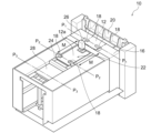
- 1 is a perspective view schematically showing an example of a metal foil cutting and stacking device according to the present invention.
- FIG. 3 is a sectional view taken along line P 2 -P 2 for explaining a state in which the metal foil is held between the chuck mechanisms in the metal foil cutting and loading device shown in FIG. 2;
- the method of cutting and stacking metal foil according to the present invention includes (a) unwinding of metal foil, (b) clamping of metal foil by a chuck mechanism, (c) cutting of metal foil, (d) conveyance of metal foil pieces, (e) ) loading the metal foil pieces by releasing them from the chuck mechanism; and (f) moving the chuck mechanism.
- Each step from (a) to (f) is then automatically performed and repeated by at least one device.
- the metal foil is cut and transported while being held by the chuck mechanism, and the metal foil pieces are released from the chuck mechanism at the loading position, thereby completing a series of operations from cutting the metal foil to loading.
- FIGS. 1A and 1B conceptually show a series of steps in the method for cutting and stacking metal foil according to the present invention.
- FIG. 2 shows a metal foil cutting and stacking device 10 used in such a metal foil cutting and stacking method.
- the metal foil cutting and loading device 10 includes a supply roll 14, a pedestal 16, a chuck mechanism 18, a cutter 20, a loading section 22, a moving mechanism 24, and a control section (not shown).
- FIGS. 1A and 1B are depicted as having different positions and orientations of members from the metal foil cutting and loading apparatus 10 according to the specific form shown in FIG. 2.
- each process from steps (a) to (f) and each component of the metal foil cutting and loading device 10 will be explained with reference to these figures.
- each step (a) to (f) is automatically performed and repeated by at least one device.
- the metal foil 12 is unrolled onto the base 16 from the metal foil roll (step (a)).
- the metal foil 12 may be unwound from the metal foil roll by rotating the supply roll 14.
- the pedestal 16 is not particularly limited as long as it is a structure such as a stage that has a flat surface on which the unwound metal foil 12 is placed.
- pedestal 16 is made of metal. If the pedestal 16 is made of metal, static electricity is less likely to be generated (or the generated static electricity can be released), so it is possible to avoid the metal foil 12 from sticking to the pedestal 16 due to static electricity, and the subsequent process (b) ) to (e) can be performed more smoothly. In addition, suppressing the generation of static electricity also leads to a reduction in displacement of the metal foil pieces 12a when the metal foil pieces 12a are loaded.
- the material of the metal foil 12 is not particularly limited.
- Examples of the metal foil 12 include aluminum foil, copper foil, stainless steel foil, nickel foil, etc., and preferably copper foil.
- the copper foil may be either rolled copper foil or electrolytic copper foil.
- step (b) Clamping of the metal foil by the chuck mechanism
- a part of the unwound metal foil 12 (for example, the end in the width direction) is held at the first position P1 by the chuck mechanism 18.
- step (b) By clamping the metal foil 12 before cutting, the metal foil 12 or the metal foil piece 12a can be clamped at the same position each time, which leads to prevention of misalignment.
- the chuck mechanism 18 is not particularly limited as long as it can hold the unwound metal foil 12 at the first position P1 , and any known configuration may be adopted.
- the chuck mechanism 18 includes a pair of plate-like members that sandwich the metal foil 12 from above and below, and a movable part that moves the pair of plate-like members so that the metal foil 12 can be held and released.
- the surface of the portion of the chuck mechanism 18 that clamps the metal foil 12 is preferably made of a material that has elasticity and is less likely to cause electrostatic damage because the surface of the metal foil 12 is less likely to be scratched.
- Preferred examples of such materials include resins, fibers, and the like.
- Preferred examples of the resin include urethane rubber, silicone resin, etc., and preferred examples of the fiber include felt.
- the first position P1 is located on the downstream side of the cutter 20 with respect to the unwinding direction of the metal foil 12, so that the chuck mechanism 18 holds the metal foil 12 during cutting, and also holds the metal foil 12 after cutting.
- the metal foil piece 12a can be conveyed to the stacking section 22 while being held. From this point of view, as shown in FIGS. 2 and 3, it is preferable that the metal foil piece 12a be held in at least two places by the chuck mechanism 18, since the metal foil piece 12a can be held stably. More preferably, as shown in FIG. 2, at least two locations are located on two mutually parallel sides constituting the outer periphery of the metal foil 12, and the two mutually parallel sides are aligned with the moving direction M of the chuck mechanism 18. parallel.
- a space is provided for holding the metal foil by the chuck mechanism 18.
- a slit notch
- Step (c) Cutting the metal foil As shown in FIG. 1A (iii), the metal foil 12 is cut on the pedestal 16 while being held by the chuck mechanism 18 to obtain individualized metal foil pieces 12a. (Step (c)). By doing so, the position of the metal foil 12 is fixed by the chuck mechanism 18, so that the displacement of the metal foil pieces 12a during loading can be reduced. Furthermore, it becomes possible to cut the metal foil 12 at an accurate position determined each time.
- the metal foil 12 may be cut with the metal foil 12 in contact with the pedestal 16, or a part or all of the metal foil 12 may be cut by blowing air toward the lower surface of the metal foil 12 from the opening of the pedestal 16. You may perform this while floating from the pedestal 16. By bringing the metal foil 12 into contact with the pedestal 16, continuous and stable cutting can be performed. On the other hand, by floating the metal foil 12, it is possible to suppress the generation of static electricity during cutting and reduce positional deviation when forming the metal foil pieces 12a.
- the cutter 20 is not particularly limited as long as it can cut the metal foil 12 on the pedestal 16 into individual metal foil pieces 12a.
- Examples of the cutter 20 include a rotary cutter, a guillotine cutter, and the like.
- a cutter of a type that presses the metal foil 12 against the base 16 with one blade may be used, or a cutter of a type that cuts the metal foil 12 from above and below with two blades, an upper blade and a lower blade.
- a cutter with two blades, an upper blade and a lower blade by providing a slit in the pedestal 16 so that the lower blade can contact the metal foil 12 from below the slit, the metal foil 12 can be contacted from above.
- the structure may be such that the metal foil 12 is sandwiched together with the upper blade.
- the size of the metal foil piece 12a is not particularly limited, but is preferably from 200 mm x 200 mm to 1500 mm x 1500 mm, more preferably from 300 mm x 300 mm to 1000 mm x 1000 mm, and most preferably from 400 mm x 400 mm to 700 mm x 700 mm. .
- step (d) Conveying the metal foil piece As shown in FIG. 1B(iv), by moving the chuck mechanism 18 to the second position P2 , the metal foil piece 12a held by the chuck mechanism 18 is removed from the base 16. It is transported to a distant loading section 22 (step (d)). Since the metal foil piece 12a is conveyed while being held by the chuck mechanism 18, additional steps such as suction of the metal foil piece 12a (as disclosed in Patent Document 2) are not necessary, so the takt time can be shortened. can. In addition, the metal foil pieces 12a can be conveyed without being misaligned by being held by the chuck mechanism 18, and as a result, misalignment of the metal foil pieces 12a during loading in the subsequent step (e) can be reduced.
- the loading section 22 is not particularly limited as long as it provides a place for the metal foil pieces 12a to be stacked, but preferably has a flat surface so that the metal foil pieces 12a can be stacked flatly. .
- the second position P2 is a position corresponding to the loading section 22, so that when the chuck mechanism 18 releases the metal foil piece 12a in the subsequent step (e), the second position P2 is a position corresponding to the loading section 22.
- the metal foil pieces 12a can be stacked accurately without positional deviation.
- the moving direction M of the chuck mechanism 18 that is, the conveyance direction of the metal foil piece 12a
- the second position P 2 is a position moved from the first position P 1 by a predetermined distance in the unwinding direction (downstream direction) of the metal foil 12 . In this case, it is desirable that the distance between the first position P1 and the second position P2 be longer than the length of the metal foil piece 12a.
- Movement of the chuck mechanism 18 is performed by a moving mechanism 24.
- the moving mechanism 24 is not particularly limited as long as it is a mechanism for reciprocating the chuck mechanism 18 between the first position P1 and the second position P2 .
- the moving mechanism 24 preferably includes a rail and a motor for driving the chuck mechanism 18 that is provided so as to be slidable along the rail.
- the rails are provided parallel to the unwinding direction of the metal foil 12. More preferably, one rail is provided on each side of the metal foil piece 12a in the width direction (i.e., two rails in total) so that the chuck mechanism 18 can move while holding both ends of the metal foil piece 12a in the width direction. Preferably, it is provided.
- the metal foil cutting and loading device 10 further includes an air injector for blowing air toward the lower surface of the metal foil piece 12a.
- the base 16 has an opening and that the air injector is arranged below the opening of the base 16.
- the metal foil cutting and stacking device 10 further includes a pressing member 26 disposed above the stacking section 22 for pressing down a part of the metal foil piece 12a.
- the metal foil cutting and loading device 10 may be provided with a disposal section 28 separately from the loading section 22.
- the cut metal foil pieces 12a are visually inspected or checked for defects such as scratches or folds using an inspection means such as a sensor, and the moving mechanism 24 loads metal foil pieces 12a that are determined to be defective.
- the metal foil piece 12a is released by transporting it to a third position P3 corresponding to the waste section 28 (for example, passing through the loading section 22) instead of the section 22.
- the operation of the moving mechanism 24 in this case is the same as the operation in the loading section 22, except that it moves to the third position P3 instead of the second position P2 (and then returns to the first position P1 ).
- the operation of the chuck mechanism 18 to release the metal foil piece 12a can also be the same as the operation in the loading section 22.
- step (e) Loading of the metal foil piece by releasing it from the chuck mechanism As shown in FIG . are loaded on the loading section 22 (step (e)).
- the metal foil piece 12a When the metal foil piece 12a is released from the chuck mechanism 18, it naturally falls to a desired position and is placed on the surface of the loading section 22 or on the metal foil piece 12a that has already been loaded. Therefore, the metal foil pieces 12a can be stacked without rubbing against the surface of the stacking section 22 or the metal foil pieces 12a that are already loaded, making it difficult for the metal foil pieces 12a to be scratched.
- the metal foil pieces 12a can be loaded at the second position P2 , which is accurately positioned by the chuck mechanism 18. If necessary, a positioning guide may be provided at the end of the loading section 22 as appropriate.
- the metal foil pieces 12a can be stacked at more accurate positions.
- it is not necessary to provide a positioning guide and in that case, damage caused by contact between the metal foil piece 12a and the positioning guide can be reduced. Therefore, an appropriate mode may be selected depending on the quality requirements for the metal foil actually handled.
- This loading method contributes to reducing displacement of the metal foil pieces 12a during loading and to reducing scratches on the metal foil pieces 12a.
- step (f) Movement of the chuck mechanism
- the chuck mechanism 18 is moved back to the first position P1 (step (f)).
- FIG. 1B(vii) which is the same diagram as FIG. 1A(i)
- a desired number of metal foil pieces 12a can be sequentially stacked on the stacking section 22.
- the metal foil roll can be processed into a stack of a plurality of metal foil pieces 12a suitable for shipping.
- each step from steps (a) to (f) is automatically performed and repeated by at least one device.
- the metal foil cutting and loading device 10 is equipped with a control section (not shown).
- the control unit controls the supply roll 14, the chuck mechanism 18, the cutter 20, the moving mechanism 24, and the presser (if any) so as to automatically perform the operations of each step from steps (a) to (f).
- Control member 26 Therefore, there may be multiple controllers. For example, after cutting the metal foil 12 in step (c), at the timing when the upper blade of the cutter 20 returns to its original position, the control unit issues a cutting end signal, and upon receiving this signal, the moving mechanism 24 starts conveying. It is sufficient if the configuration is such that
- the metal foil cutting and loading device 10 includes an operation panel and/or a touch panel panel, and can be configured to allow operation, instruction, and monitoring by an operator.
- the operator can press a predetermined button to transfer the metal foil piece 12a to the moving mechanism 24 (
- a configuration may also be adopted in which an instruction is issued via the control unit to transport to the disposal unit 28 (instead of the loading unit 22).
Landscapes
- Life Sciences & Earth Sciences (AREA)
- Forests & Forestry (AREA)
- Engineering & Computer Science (AREA)
- Mechanical Engineering (AREA)
- Collation Of Sheets And Webs (AREA)
- Fixed Capacitors And Capacitor Manufacturing Machines (AREA)
Abstract
金属箔の切断から積載までの一連の作業をタクトタイムの短縮、積載時における金属箔片の位置ズレの低減、及び金属箔片におけるキズの低減を図りながら自動化する、金属箔の切断積載方法が提供される。この方法は、(a)金属箔ロールから台座上に金属箔を巻き出す工程と、(b)巻き出された金属箔の一部を第一の位置でチャック機構により挟持する工程と、(c)チャック機構で金属箔を挟持しながら、金属箔を台座上で切断して、個別化された金属箔片とする工程と、(d)チャック機構を第二の位置まで移動させることで、チャック機構で挟持された金属箔片を台座から離れた積載部に搬送する工程と、(e)第二の位置でチャック機構から金属箔片を解放し、それにより金属箔片を積載部に積載する工程と、(f)チャック機構を第一の位置に戻すように移動させる工程と、を含み、(a)から(f)までの各工程が少なくとも1つの装置によって自動的に実施され、かつ、繰り返される。
Description
本発明は、金属箔の切断積載方法及び金属箔切断積載装置に関するものである。
金属箔は、ロール・トゥ・ロールで製造されるため、製造直後はロール状の形態である。この金属箔ロールをそのままの形態で出荷することもあれば、所定サイズに切断されたシート片の形態で梱包して出荷することもある。近年、シート片の金属箔に対するニーズが高まっており、シート片の形態で金属箔を出荷するケースが増えつつある。
金属箔ロールから巻き出された金属箔を切断するための金属箔切断装置が知られている。例えば、特許文献1(特開2003-1591号公報)には、ロールから巻き出された金属箔を挟持する一対のピンチローラと、金属箔を切断するためのカッターと、吸引によって金属箔を保持可能な吸引搬送装置とを備えた装置が開示されている。この装置によれば、ロールから巻き出された金属箔の端部近傍を吸引保持した状態で金属箔を切断できるため、金属箔の切断効率が改善されるとされている。
金属箔を切断する機能に加えて、切断した金属箔シートを積載する機能をも備えた装置も提案されている。例えば、特許文献2(特開昭60-20900号公報)には、金属箔ロールより金属箔を搬送するフィードロールと、金属箔を切断するカッターと、切断された金属箔シートを搬送するサクションベルトを備えたベルトコンベヤと、サクションベルト上の金属箔シートを吸引及び搬送して所定場所に積載するフィーダとを備えた装置が開示されている。
金属箔ロールから巻き出された金属箔を自動切断機で所定サイズのシート片に切断した場合、切断された金属箔片を所定位置まで移動させて所定枚数まで積載する作業は、人間による手作業で行われているのが現状である。したがって、これらの一連の作業を自動化できれば好都合である。切断から積載までの工程を自動化するには、タクトタイムの短縮、積載時における金属箔片の位置ズレの低減、及び積載時における金属箔片に発生するキズの低減が望まれる。特許文献2には積載機能も備えた切断装置が開示されているが、金属箔片を吸引して搬送する構成を含むため、搬送及び積載に伴うにタクトタイムが長くなる上、積載時における金属箔片の位置ズレも起こりやすいという問題がある。
本発明者らは、今般、チャック機構で金属箔を挟持しながら金属箔の切断及び搬送を行い、積載位置でチャック機構から金属箔片を解放することで、金属箔の切断から積載までの一連の作業をタクトタイムの短縮、積載時における金属箔片の位置ズレの低減、及び金属箔片におけるキズの低減を図りながら自動化できるとの知見を得た。
したがって、本発明の目的は、金属箔の切断から積載までの一連の作業をタクトタイムの短縮、積載時における金属箔片の位置ズレの低減、及び金属箔片におけるキズの低減を図りながら自動化することにある。
本発明の一態様によれば、金属箔の切断積載方法であって、
(a)金属箔ロールから台座上に金属箔を巻き出す工程と、
(b)巻き出された前記金属箔の一部を第一の位置でチャック機構により挟持する工程と、
(c)前記チャック機構で前記金属箔を挟持しながら、前記金属箔を前記台座上で切断して、個別化された金属箔片とする工程と、
(d)前記チャック機構を第二の位置まで移動させることで、前記チャック機構で挟持された前記金属箔片を前記台座から離れた積載部に搬送する工程と、
(e)前記第二の位置で前記チャック機構から前記金属箔片を解放し、それにより前記金属箔片を前記積載部に積載する工程と、
(f)前記チャック機構を前記第一の位置に戻すように移動させる工程と、
を含み、前記(a)から前記(f)までの各工程が少なくとも1つの装置によって自動的に実施され、かつ、繰り返される、金属箔の切断積載方法が提供される。
本発明の他の一態様によれば、前記金属箔の切断積載方法に用いられる金属箔切断積載装置であって、
金属箔ロールから金属箔を巻き出すための供給ロールと、
巻き出された前記金属箔が載置されるための台座と、
巻き出された前記金属箔を前記第一の位置で挟持可能なチャック機構と、
前記金属箔を前記台座上で切断して個別化された金属箔片とするためのカッターと、
前記金属箔片が積載されるための積載部と、
前記チャック機構を前記第一の位置と前記第二の位置の間で往復移動させるための移動機構と、
前記(a)から前記(f)までの各工程の動作を自動的に行うように、前記供給ロール、前記チャック機構、前記カッター、及び前記移動機構を制御する少なくとも1つの制御部と、
を備えた、金属箔切断積載装置が提供される。
金属箔ロールから金属箔を巻き出すための供給ロールと、
巻き出された前記金属箔が載置されるための台座と、
巻き出された前記金属箔を前記第一の位置で挟持可能なチャック機構と、
前記金属箔を前記台座上で切断して個別化された金属箔片とするためのカッターと、
前記金属箔片が積載されるための積載部と、
前記チャック機構を前記第一の位置と前記第二の位置の間で往復移動させるための移動機構と、
前記(a)から前記(f)までの各工程の動作を自動的に行うように、前記供給ロール、前記チャック機構、前記カッター、及び前記移動機構を制御する少なくとも1つの制御部と、
を備えた、金属箔切断積載装置が提供される。
本発明による金属箔の切断積載方法は、(a)金属箔の巻き出し、(b)金属箔のチャック機構による挟持、(c)金属箔の切断、(d)金属箔片の搬送、(e)チャック機構からの解放による金属箔片の積載、及び(f)チャック機構の移動の各工程を含む。そして、(a)から(f)までの各工程が少なくとも1つの装置によって自動的に実施され、かつ、繰り返される。この方法によれば、チャック機構で金属箔を挟持しながら金属箔の切断及び搬送を行い、積載位置でチャック機構から金属箔片を解放することで、金属箔の切断から積載までの一連の作業をタクトタイムの短縮、積載時における金属箔片の位置ズレの低減、及び金属箔片におけるキズの低減を図りながら自動化することができる。すなわち、従来、自動切断機で切断された金属箔片を所定位置まで搬送させて所定枚数まで積載する作業が人間による手作業で行われていたが、本発明の方法によりこれらの一連の作業を自動化することができる。しかも、タクトタイムの短縮、積載時における金属箔片の位置ズレの低減、及び金属箔片におけるキズの低減をも図ることができる。
図1A及び1Bに、本発明による金属箔の切断積載方法の一連の工程を概念的に示す。また、図2に、そのような金属箔の切断積載方法に用いられる金属箔切断積載装置10を示す。金属箔切断積載装置10は、供給ロール14と、台座16と、チャック機構18と、カッター20と、積載部22と、移動機構24と、制御部(図示せず)とを備える。なお、図1A及び1Bは本発明の概念を分かりやすく示すため、図2に示される具体的な形態による金属箔切断積載装置10とは、部材の位置や向きが異なるものとして描かれている。
以下、これらの図を参照しながら、工程(a)から(f)までの各工程及び金属箔切断積載装置10の各構成要素について説明する。上述のとおり、(a)から(f)までの各工程は、少なくとも1つの装置によって自動的に実施され、かつ、繰り返される。
(a)金属箔の巻き出し
図1A(i)に示されるように、金属箔ロールから台座16上に金属箔12を巻き出す(工程(a))。金属箔ロールからの金属箔12の巻き出しは供給ロール14の回転により行えばよい。台座16は、巻き出された金属箔12が載置されるための平坦面を備えたステージ等の構造物であれば、特に限定されない。好ましくは、台座16は金属製である。台座16が金属製であると、静電気が発生しにくくなる(あるいは発生した静電気を逃がすことができる)ため、金属箔12が静電気で台座16に張り付くのを避けることができ、後続の工程(b)から(e)までの作業をよりスムーズに行うことが可能となる。また、静電気の発生抑制は、金属箔片12aの積載時における金属箔片12aの位置ズレの低減にもつながる。
図1A(i)に示されるように、金属箔ロールから台座16上に金属箔12を巻き出す(工程(a))。金属箔ロールからの金属箔12の巻き出しは供給ロール14の回転により行えばよい。台座16は、巻き出された金属箔12が載置されるための平坦面を備えたステージ等の構造物であれば、特に限定されない。好ましくは、台座16は金属製である。台座16が金属製であると、静電気が発生しにくくなる(あるいは発生した静電気を逃がすことができる)ため、金属箔12が静電気で台座16に張り付くのを避けることができ、後続の工程(b)から(e)までの作業をよりスムーズに行うことが可能となる。また、静電気の発生抑制は、金属箔片12aの積載時における金属箔片12aの位置ズレの低減にもつながる。
金属箔12の材質は特に限定されない。金属箔12の例としては、アルミニウム箔、銅箔、ステンレス鋼箔、ニッケル箔等が挙げられ、好ましくは銅箔である。銅箔は圧延銅箔及び電解銅箔のいずれであってもよい。
(b)金属箔のチャック機構による挟持
図1A(ii)に示されるように、巻き出された金属箔12の一部(例えば幅方向の端部)を第一の位置P1でチャック機構18により挟持する(工程(b))。金属箔12を切断前に挟持することで、金属箔12ないし金属箔片12aを毎回同じ位置で挟持することができ、位置ズレの防止につながる。チャック機構18は、巻き出された金属箔12を第一の位置P1で挟持可能な機構であれば特に限定されず、公知の構成を採用すればよい。例えば、チャック機構18は、金属箔12を上下から挟み込む1対の板状部材と、金属箔12を挟持及び解放可能に1対の板状部材を動かす可動部とを備える。チャック機構18の金属箔12を挟持する部分の表面は、弾力性を有し、かつ、静電気障害を起こしにくい材料で構成されるのが、金属箔12の表面にキズがつきにくくなるため好ましい。そのような材料の好ましい例としては、樹脂、繊維等が挙げられる。樹脂の好ましい例としては、ウレタンゴム、シリコーン樹脂等が挙げられ、繊維の好ましい例としては、フェルト等が挙げられる。
図1A(ii)に示されるように、巻き出された金属箔12の一部(例えば幅方向の端部)を第一の位置P1でチャック機構18により挟持する(工程(b))。金属箔12を切断前に挟持することで、金属箔12ないし金属箔片12aを毎回同じ位置で挟持することができ、位置ズレの防止につながる。チャック機構18は、巻き出された金属箔12を第一の位置P1で挟持可能な機構であれば特に限定されず、公知の構成を採用すればよい。例えば、チャック機構18は、金属箔12を上下から挟み込む1対の板状部材と、金属箔12を挟持及び解放可能に1対の板状部材を動かす可動部とを備える。チャック機構18の金属箔12を挟持する部分の表面は、弾力性を有し、かつ、静電気障害を起こしにくい材料で構成されるのが、金属箔12の表面にキズがつきにくくなるため好ましい。そのような材料の好ましい例としては、樹脂、繊維等が挙げられる。樹脂の好ましい例としては、ウレタンゴム、シリコーン樹脂等が挙げられ、繊維の好ましい例としては、フェルト等が挙げられる。
第一の位置P1は、金属箔12の巻き出し方向に照らしてカッター20の下流側に位置しており、それにより、チャック機構18は、切断時には金属箔12を保持するとともに、切断後には金属箔片12aを保持したまま積載部22に搬送することができる。かかる観点から、図2及び3に示されるように、金属箔片12aの少なくとも2箇所がチャック機構18によって挟持されるのが金属箔片12aを安定的に保持できる点で好ましい。より好ましくは、図2に示されるように、少なくとも2箇所が、金属箔12の外周を構成する互いに平行な2辺に位置しており、互いに平行な2辺がチャック機構18の移動方向Mと平行である。
チャック機構18によって金属箔を挟持するための空間が設けられていることが好ましい。例えば、台座16にスリット(切り欠け部)を設け、そのスリットの上下から金属箔片12aを挟持し、その後搬送する構成とするのがよい。こうすることで位置ズレの低減が可能になる。また、巻き出された金属箔12の一部が台座16からはみ出しており、このはみだした端部がチャック機構18によって挟持されてもよい。この場合は、簡素な構成で、切断後に金属箔片12aを保持したまま積載部22に搬送することができる。
(c)金属箔の切断
図1A(iii)に示されるように、チャック機構18で金属箔12を挟持しながら、金属箔12を台座16上で切断して、個別化された金属箔片12aとする(工程(c))。こうすることで、チャック機構18で金属箔12の位置が固定されるため、積載時における金属箔片12aの位置ズレを低減できる。また、毎回位置決められた正確な位置での金属箔12の切断も可能になる。
図1A(iii)に示されるように、チャック機構18で金属箔12を挟持しながら、金属箔12を台座16上で切断して、個別化された金属箔片12aとする(工程(c))。こうすることで、チャック機構18で金属箔12の位置が固定されるため、積載時における金属箔片12aの位置ズレを低減できる。また、毎回位置決められた正確な位置での金属箔12の切断も可能になる。
金属箔12の切断は、金属箔12を台座16に接触させた状態で行ってもよいし、台座16の開口部から金属箔12の下面に向けて空気を吹き付けて金属箔12の一部分又は全部を台座16から浮かせながら行ってもよい。金属箔12を台座16に接触させることで、連続的に安定して切断を行うことができる。一方、金属箔12を浮かせることで、切断時における静電気の発生を抑制し、金属箔片12aとする際の位置ズレを低減できる。
カッター20は、金属箔12を台座16上で切断して個別化された金属箔片12aとすることができるものであれば特に限定されない。カッター20の例としては、ロータリーカッター、ギロチンカッター等が挙げられる。また、1枚の刃で金属箔12を台座16に対して押し切るタイプのカッターでもよいし、上刃及び下刃の2枚刃で上下から金属箔12を挟み切るタイプのカッターでもよい。上刃及び下刃の2枚刃のカッターの場合、台座16にスリットを設けてスリットの下から下刃を金属箔12に当接できるようにすることで、金属箔12の上方から当接される上刃とともに金属箔12を挟み切る構成とすればよい。
金属箔片12aのサイズは特に限定されないが、好ましくは200mm×200mmから1500mm×1500mmまで、より好ましくは300mm×300mmから1000mm×1000mmまで、最も好ましくは400mm×400mmから700mm×700mmまでのサイズである。
(d)金属箔片の搬送
図1B(iv)に示されるように、チャック機構18を第二の位置P2まで移動させることで、チャック機構18で挟持された金属箔片12aを台座16から離れた積載部22に搬送する(工程(d))。金属箔片12aをチャック機構18で挟持したまま搬送するため、(特許文献2に開示されるような)金属箔片12aの吸引等の追加のステップが不要なため、タクトタイムを短くすることができる。また、チャック機構18による挟持により金属箔片12aを、位置ズレを起こすことなく搬送でき、その結果、後続の工程(e)の積載時における金属箔片12aの位置ズレを低減できる。積載部22は、金属箔片12aが積載されるための場所を提供するものであれば特に限定されないが、金属箔片12aを平らに積載できるように平坦な表面を有しているのが好ましい。
図1B(iv)に示されるように、チャック機構18を第二の位置P2まで移動させることで、チャック機構18で挟持された金属箔片12aを台座16から離れた積載部22に搬送する(工程(d))。金属箔片12aをチャック機構18で挟持したまま搬送するため、(特許文献2に開示されるような)金属箔片12aの吸引等の追加のステップが不要なため、タクトタイムを短くすることができる。また、チャック機構18による挟持により金属箔片12aを、位置ズレを起こすことなく搬送でき、その結果、後続の工程(e)の積載時における金属箔片12aの位置ズレを低減できる。積載部22は、金属箔片12aが積載されるための場所を提供するものであれば特に限定されないが、金属箔片12aを平らに積載できるように平坦な表面を有しているのが好ましい。
したがって、第二の位置P2は、積載部22に対応する位置であり、それにより後続の工程(e)でチャック機構18が金属箔片12aを解放した場合に、積載部22の所定位置に金属箔片12aが位置ズレなく正確に積載されることができる。図2に示されるように、チャック機構18の移動方向M(すなわち金属箔片12aの搬送方向)は、金属箔12の巻き出し方向(金属箔ロールの長尺方向)と平行となるようにするのが好ましい。したがって、第二の位置P2は、第一の位置P1を金属箔12の巻き出し方向(下流方向)に所定距離移動させた位置とするのが好ましい。この場合、第一の位置P1と第二の位置P2の離間距離は、金属箔片12aの長さよりも長いことが望まれる。
チャック機構18の移動は移動機構24により行われる。移動機構24は、チャック機構18を第一の位置P1と第二の位置P2の間で往復移動させるための機構であれば特に限定されない。例えば、移動機構24は、レールと、レールに沿ってスライド移動可能に設けられるチャック機構18を駆動するためのモーターとを備えるのが好ましい。レールは、金属箔12の巻き出し方向と平行に設けられるのが好ましい。より好ましくは、レールはチャック機構18が金属箔片12aの幅方向の両側の端部を挟持しながら移動できるように、金属箔片12aの幅方向の両側に1本ずつ(すなわち計2本)設けられるのが好ましい。
金属箔片12aを搬送する際に、台座16の開口部から金属箔片12aの下面に向けて空気を吹き付けて金属箔片12aを台座16から浮かせるのが好ましい。こうすることで、金属箔片12aが台座16の表面と擦れにくくなるため、金属箔片12aにおけるキズが発生しにくくなる。したがって、金属箔切断積載装置10は、金属箔片12aの下面に向けて空気を吹き付けるための空気インジェクタをさらに備えているのが好ましい。この場合、台座16が開口部を有しており、台座16の開口部の下方に空気インジェクタが配置されるのが好ましい。
図1B(v)に示されるように、金属箔片12aを積載部22に搬送した後、チャック機構18から金属箔片12aを解放するまで、金属箔片12aの一部を押さえ部材26で上から押さえるのが好ましい。すなわち、金属箔切断積載装置10は、積載部22の上方に配置される、金属箔片12aの一部を下方に押さえるための押さえ部材26をさらに備えるのが好ましい。チャック機構18から解放される前に金属箔片12aを押さえることで、解放時の金属箔片12aの動きを抑制することができ、積載時における金属箔片12aの位置ズレをより効果的に低減できる。
図2に示されるように金属箔切断積載装置10には積載部22とは別に廃棄部28が設けられていてもよい。この場合、切断された金属箔片12aを目視又はセンサー等の検査手段でキズや折れ等の欠陥の有無を確認して、欠陥があると判定された金属箔片12aについては移動機構24が積載部22ではなく(例えば積載部22を通過して)廃棄部28に対応する第三の位置P3に搬送して、金属箔片12aを解放する。この場合における移動機構24の動作は、第二の位置P2の代わりに第三の位置P3に移動する(その後第一の位置P1に戻る)こと以外は積載部22における動作と同じであることができ、チャック機構18が金属箔片12aを解放する動作も積載部22における動作と同じであることができる。
(e)チャック機構からの解放による金属箔片の積載
図1B(v)に示されるように、第二の位置P2でチャック機構18から金属箔片12aを解放し、それにより金属箔片12aを積載部22に積載する(工程(e))。チャック機構18からの解放により金属箔片12aが自然と所望の位置に落ちることで、積載部22の表面又は既に積載されている金属箔片12a上に載置される。したがって、積載部22の表面又は既に積載されている金属箔片12aと擦れることなく積載することができるので、金属箔片12aにキズが付きにくくなる。しかも、チャック機構18によって正確に位置決めされた第二の位置P2で金属箔片12aを積載することができる。必要に応じて、積載部22の端部に位置決めガイドを適宜設けてもよい。位置決めガイドを設けることで、より正確な位置で金属箔片12aを積載することができる。一方で、位置決めガイドを設けなくてもよく、その場合には金属箔片12aと位置決めガイドとの接触によるダメージを低減できる。したがって、実際に扱う金属箔への品質要求に応じて、相応しい態様を選択すればよい。この積載手法は、積載時における金属箔片12aの位置ズレの低減、及び金属箔片12aにおけるキズの低減に寄与する。金属箔片12aの一部を押さえ部材26で上から押さえている場合には、チャック機構18から金属箔片12aを解放された時点で押さえ部材26が上昇して初期位置に戻ることで、金属箔片12aの押さえが解除される。
図1B(v)に示されるように、第二の位置P2でチャック機構18から金属箔片12aを解放し、それにより金属箔片12aを積載部22に積載する(工程(e))。チャック機構18からの解放により金属箔片12aが自然と所望の位置に落ちることで、積載部22の表面又は既に積載されている金属箔片12a上に載置される。したがって、積載部22の表面又は既に積載されている金属箔片12aと擦れることなく積載することができるので、金属箔片12aにキズが付きにくくなる。しかも、チャック機構18によって正確に位置決めされた第二の位置P2で金属箔片12aを積載することができる。必要に応じて、積載部22の端部に位置決めガイドを適宜設けてもよい。位置決めガイドを設けることで、より正確な位置で金属箔片12aを積載することができる。一方で、位置決めガイドを設けなくてもよく、その場合には金属箔片12aと位置決めガイドとの接触によるダメージを低減できる。したがって、実際に扱う金属箔への品質要求に応じて、相応しい態様を選択すればよい。この積載手法は、積載時における金属箔片12aの位置ズレの低減、及び金属箔片12aにおけるキズの低減に寄与する。金属箔片12aの一部を押さえ部材26で上から押さえている場合には、チャック機構18から金属箔片12aを解放された時点で押さえ部材26が上昇して初期位置に戻ることで、金属箔片12aの押さえが解除される。
(f)チャック機構の移動
図1B(vi)に示されるように、金属箔片12aの積載後、チャック機構18を第一の位置P1に戻すように移動させる(工程(f))。こうすることで、図1B(vii)(図1A(i)と同じ図である)に示されるように、工程(a)に戻すことができ、工程(a)から(f)までの各工程を繰り返すことで、所望の枚数の金属箔片12aを順次積載部22に積載していくことができる。こうして、金属箔ロールを、出荷に適した複数枚の金属箔片12aの積載物に加工することができる。
図1B(vi)に示されるように、金属箔片12aの積載後、チャック機構18を第一の位置P1に戻すように移動させる(工程(f))。こうすることで、図1B(vii)(図1A(i)と同じ図である)に示されるように、工程(a)に戻すことができ、工程(a)から(f)までの各工程を繰り返すことで、所望の枚数の金属箔片12aを順次積載部22に積載していくことができる。こうして、金属箔ロールを、出荷に適した複数枚の金属箔片12aの積載物に加工することができる。
(g)その他
上述のとおり、工程(a)から(f)までの各工程が少なくとも1つの装置によって自動的に実施され、かつ、繰り返される。これを実現するため、金属箔切断積載装置10は制御部(図示せず)を備えている。制御部は、工程(a)から(f)までの各工程の動作を自動的に行うように、供給ロール14、チャック機構18、カッター20、移動機構24、及び(存在する場合には)押さえ部材26を制御する。したがって、複数の制御部が存在しうる。例えば、工程(c)で金属箔12の切断後、カッター20の上刃が元の位置に戻ったタイミングで、切断終了信号を制御部が出し、その信号を受けて移動機構24が搬送を開始する構成とすればよい。
上述のとおり、工程(a)から(f)までの各工程が少なくとも1つの装置によって自動的に実施され、かつ、繰り返される。これを実現するため、金属箔切断積載装置10は制御部(図示せず)を備えている。制御部は、工程(a)から(f)までの各工程の動作を自動的に行うように、供給ロール14、チャック機構18、カッター20、移動機構24、及び(存在する場合には)押さえ部材26を制御する。したがって、複数の制御部が存在しうる。例えば、工程(c)で金属箔12の切断後、カッター20の上刃が元の位置に戻ったタイミングで、切断終了信号を制御部が出し、その信号を受けて移動機構24が搬送を開始する構成とすればよい。
好ましくは、金属箔切断積載装置10は、操作盤及び/又はタッチパネル盤を備えており、オペレータによる操作、指示及び監視ができるように構成されうる。例えば、前述した廃棄部28を有する構成において、切断された金属箔片12aに欠陥があると判定した場合に、オペレータが所定のボタンを押すことで、移動機構24に、金属箔片12aを(積載部22の代わりに)廃棄部28に搬送するように制御部を介して指示を出す構成としてもよい。
Claims (10)
- 金属箔の切断積載方法であって、
(a)金属箔ロールから台座上に金属箔を巻き出す工程と、
(b)巻き出された前記金属箔の一部を第一の位置でチャック機構により挟持する工程と、
(c)前記チャック機構で前記金属箔を挟持しながら、前記金属箔を前記台座上で切断して、個別化された金属箔片とする工程と、
(d)前記チャック機構を第二の位置まで移動させることで、前記チャック機構で挟持された前記金属箔片を前記台座から離れた積載部に搬送する工程と、
(e)前記第二の位置で前記チャック機構から前記金属箔片を解放し、それにより前記金属箔片を前記積載部に積載する工程と、
(f)前記チャック機構を前記第一の位置に戻すように移動させる工程と、
を含み、前記(a)から前記(f)までの各工程が少なくとも1つの装置によって自動的に実施され、かつ、繰り返される、金属箔の切断積載方法。 - 前記台座が金属製である、請求項1に記載の金属箔の切断積載方法。
- 前記金属箔片を搬送する際に、前記台座の開口部から前記金属箔片の下面に向けて空気を吹き付けて前記金属箔片を前記台座から浮かせることをさらに含む、請求項1又は2に記載の金属箔の切断積載方法。
- 前記チャック機構の前記金属箔を挟持する部分の表面が樹脂又は繊維製である、請求項1~3のいずれか一項に記載の金属箔の切断積載方法。
- 前記金属箔片を前記積載部に搬送した後、前記チャック機構から前記金属箔片を解放するまで、前記金属箔片の一部を押さえ部材で上から押さえることをさらに含む、請求項1~4のいずれか一項に記載の金属箔の切断積載方法。
- 前記金属箔片の少なくとも2箇所が前記チャック機構によって挟持される、請求項1~5のいずれか一項に記載の金属箔の切断積載方法。
- 前記少なくとも2箇所が、前記金属箔の外周を構成する互いに平行な2辺に位置しており、前記互いに平行な2辺が前記チャック機構の移動方向と平行である、請求項6に記載の金属箔の切断積載方法。
- 請求項1~7のいずれか一項に記載の金属箔の切断積載方法に用いられる金属箔切断積載装置であって、
金属箔ロールから金属箔を巻き出すための供給ロールと、
巻き出された前記金属箔が載置されるための台座と、
巻き出された前記金属箔を前記第一の位置で挟持可能なチャック機構と、
前記金属箔を前記台座上で切断して個別化された金属箔片とするためのカッターと、
前記金属箔片が積載されるための積載部と、
前記チャック機構を前記第一の位置と前記第二の位置の間で往復移動させるための移動機構と、
前記(a)から前記(f)までの各工程の動作を自動的に行うように、前記供給ロール、前記チャック機構、前記カッター、及び前記移動機構を制御する少なくとも1つの制御部と、
を備えた、金属箔切断積載装置。 - 前記台座が開口部を有しており、
前記金属箔切断積載装置が、前記台座の開口部の下方に配置される、前記金属箔片の下面に向けて空気を吹き付けるための空気インジェクタをさらに備えた、請求項8に記載の金属箔切断積載装置。 - 前記金属箔切断積載装置が、前記積載部の上方に配置される、前記金属箔片の一部を下方に押さえるための押さえ部材をさらに備えた、請求項8又は9に記載の金属箔切断積載装置。
Priority Applications (2)
| Application Number | Priority Date | Filing Date | Title |
|---|---|---|---|
| PCT/JP2022/012682 WO2023175925A1 (ja) | 2022-03-18 | 2022-03-18 | 金属箔の切断積載方法及び金属箔切断積載装置 |
| TW112109981A TW202400389A (zh) | 2022-03-18 | 2023-03-17 | 金屬箔之切斷裝載方法及金屬箔切斷裝載裝置 |
Applications Claiming Priority (1)
| Application Number | Priority Date | Filing Date | Title |
|---|---|---|---|
| PCT/JP2022/012682 WO2023175925A1 (ja) | 2022-03-18 | 2022-03-18 | 金属箔の切断積載方法及び金属箔切断積載装置 |
Publications (1)
| Publication Number | Publication Date |
|---|---|
| WO2023175925A1 true WO2023175925A1 (ja) | 2023-09-21 |
Family
ID=88023010
Family Applications (1)
| Application Number | Title | Priority Date | Filing Date |
|---|---|---|---|
| PCT/JP2022/012682 WO2023175925A1 (ja) | 2022-03-18 | 2022-03-18 | 金属箔の切断積載方法及び金属箔切断積載装置 |
Country Status (2)
| Country | Link |
|---|---|
| TW (1) | TW202400389A (ja) |
| WO (1) | WO2023175925A1 (ja) |
Citations (7)
| Publication number | Priority date | Publication date | Assignee | Title |
|---|---|---|---|---|
| JPS4726461Y1 (ja) * | 1967-08-29 | 1972-08-15 | ||
| JPS5286181U (ja) * | 1975-12-23 | 1977-06-27 | ||
| JPS6020900A (ja) * | 1983-07-15 | 1985-02-02 | 松下電工株式会社 | 金属箔シ−トの搬送積載装置 |
| JPH0269995U (ja) * | 1988-11-11 | 1990-05-28 | ||
| JPH07237798A (ja) * | 1994-02-25 | 1995-09-12 | N C Ee:Kk | シート状物引出し装置 |
| JP2003001591A (ja) * | 2001-06-21 | 2003-01-08 | Shinko Electric Co Ltd | 金属箔切断装置 |
| JP2007022733A (ja) * | 2005-07-14 | 2007-02-01 | Inoac Corp | シート積載装置 |
-
2022
- 2022-03-18 WO PCT/JP2022/012682 patent/WO2023175925A1/ja unknown
-
2023
- 2023-03-17 TW TW112109981A patent/TW202400389A/zh unknown
Patent Citations (7)
| Publication number | Priority date | Publication date | Assignee | Title |
|---|---|---|---|---|
| JPS4726461Y1 (ja) * | 1967-08-29 | 1972-08-15 | ||
| JPS5286181U (ja) * | 1975-12-23 | 1977-06-27 | ||
| JPS6020900A (ja) * | 1983-07-15 | 1985-02-02 | 松下電工株式会社 | 金属箔シ−トの搬送積載装置 |
| JPH0269995U (ja) * | 1988-11-11 | 1990-05-28 | ||
| JPH07237798A (ja) * | 1994-02-25 | 1995-09-12 | N C Ee:Kk | シート状物引出し装置 |
| JP2003001591A (ja) * | 2001-06-21 | 2003-01-08 | Shinko Electric Co Ltd | 金属箔切断装置 |
| JP2007022733A (ja) * | 2005-07-14 | 2007-02-01 | Inoac Corp | シート積載装置 |
Also Published As
| Publication number | Publication date |
|---|---|
| TW202400389A (zh) | 2024-01-01 |
Similar Documents
| Publication | Publication Date | Title |
|---|---|---|
| KR102186952B1 (ko) | 메탈필름롤 재단시스템 | |
| JP2012054300A (ja) | 変圧器鉄心の製造装置および製造方法 | |
| CN100577542C (zh) | 超长薄膜的运送装置和运送方法 | |
| JP5146903B2 (ja) | ガラス基板梱包装置 | |
| JP2011527267A (ja) | 裁断片積層体を取り巻く帯封を切断する方法と装置 | |
| TWI500528B (zh) | 用於打印機的箔片引導裝置 | |
| JP3107807B2 (ja) | シート積み上げ装置 | |
| WO2023175925A1 (ja) | 金属箔の切断積載方法及び金属箔切断積載装置 | |
| EP3670437A1 (en) | Multi-conveyor belt based insertion mechanism for pocketed coil springs | |
| TWI280086B (en) | Flexible PCB transferring apparatus | |
| KR101683836B1 (ko) | 필름 이송 장력조절용 진공장치 | |
| JP2015120209A (ja) | 打ち抜き切断装置 | |
| KR102226078B1 (ko) | 금속 다공체 제조용 물류 반송 장치 | |
| CN210336164U (zh) | 保护片材切断装置 | |
| KR101969826B1 (ko) | 노칭 가공기 | |
| JP7053884B2 (ja) | スタンピングフォイルを駆動する装置、スタンピングステーション及びスタンピング機、及びスタンピングフォイルの駆動を制御する方法 | |
| JP7130244B2 (ja) | 積層コア形成用の積層材製造装置 | |
| US6872044B2 (en) | Apparatus for and method of manufacturing sheets | |
| JPH06206201A (ja) | ランニングソーシステム | |
| WO2022219871A1 (ja) | ガラス板梱包体の製造方法及びガラス板梱包体 | |
| EP3782821B1 (en) | Paper stack press machine | |
| WO2016199447A1 (ja) | 帯状板の接合方法 | |
| JP2023133770A (ja) | シート製造方法及びシート製造装置 | |
| JPH06255001A (ja) | 紙管製造装置 | |
| JP7428180B2 (ja) | 保護シート切断装置及びガラス基板梱包体の製造方法 |
Legal Events
| Date | Code | Title | Description |
|---|---|---|---|
| 121 | Ep: the epo has been informed by wipo that ep was designated in this application |
Ref document number: 22932197 Country of ref document: EP Kind code of ref document: A1 |