WO2023175775A1 - 空気調和機 - Google Patents
空気調和機 Download PDFInfo
- Publication number
- WO2023175775A1 WO2023175775A1 PCT/JP2022/011920 JP2022011920W WO2023175775A1 WO 2023175775 A1 WO2023175775 A1 WO 2023175775A1 JP 2022011920 W JP2022011920 W JP 2022011920W WO 2023175775 A1 WO2023175775 A1 WO 2023175775A1
- Authority
- WO
- WIPO (PCT)
- Prior art keywords
- thermal image
- air
- air conditioner
- air conditioning
- unit
- Prior art date
- Legal status (The legal status is an assumption and is not a legal conclusion. Google has not performed a legal analysis and makes no representation as to the accuracy of the status listed.)
- Ceased
Links
Images




Classifications
-
- F—MECHANICAL ENGINEERING; LIGHTING; HEATING; WEAPONS; BLASTING
- F24—HEATING; RANGES; VENTILATING
- F24F—AIR-CONDITIONING; AIR-HUMIDIFICATION; VENTILATION; USE OF AIR CURRENTS FOR SCREENING
- F24F2110/00—Control inputs relating to air properties
- F24F2110/50—Air quality properties
Definitions
- the present disclosure relates to an air conditioner.
- Patent Document 1 there is an air conditioner that non-contactly senses the user's biological information and determines whether the user is awake or asleep to control the air conditioning (for example, Patent Document 1).
- the air conditioner described in Patent Document 1 not only uses the determination result of whether the user is awake or asleep for air conditioning control, but also outputs it as report data to external equipment, making it possible to understand the user's health condition, etc. It has the function of
- the present disclosure has been made in view of the above, and aims to provide an air conditioner that can accurately determine a user's health condition and notify the outside.
- an air conditioner includes a receiving unit that receives an air conditioning operation command from a remote controller, and a receiving unit that receives an air conditioning operation command from a remote controller, and a receiving unit that receives an air conditioning operation command from a remote controller, and a heat receiving unit that receives an air conditioning operation command from a remote controller,
- a thermal image sensor that acquires image data
- a vital sensor that acquires biological data of a person who is present in an air-conditioned space
- a storage unit that stores air-conditioning operation commands, thermal image data, and biological data
- a determination section that determines the health condition of the subject based on the air conditioning operation command, thermal image data, and biological data stored in the system, and a transmission section that transmits the determination result by the determination section to an external information terminal.
- the air conditioner according to the present disclosure has the effect of being able to determine the user's health condition with high accuracy and notify the outside.
- a diagram showing a configuration example of an air conditioner according to an embodiment Diagram showing an example of the installation position of the thermal image sensor and vital sensor when looking at the indoor unit from the front
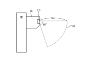
- Diagram showing an example of the installation position of the thermal image sensor and vital sensor when looking at the indoor unit from the side
- Flowchart showing an example of the operation of an air conditioner Diagram showing an example of hardware that realizes an indoor unit of an air conditioner
- FIG. 1 is a diagram illustrating a configuration example of an air conditioner according to an embodiment of the present disclosure.
- Air conditioner 100 according to the present embodiment shown in FIG. 1 includes an indoor unit 10 and a remote controller 20.
- the indoor unit 10 includes a measuring section 1 , a receiving section 4 , a storage section 7 , a determining section 8 , and a transmitting section 9 .
- the measurement unit 1 is located in a thermal image sensor 2 that acquires a thermal image of a predetermined range of the room in which the indoor unit 10 is installed, and in an air-conditioned space that is a space to which the air conditioner 100 performs air conditioning. It includes a vital sensor 3 that acquires biological data including at least a person's pulse and breathing rate.
- the thermal image sensor 2 detects the temperature of the air-conditioned space and the temperature of the user of the air conditioner 100, and outputs the detection results to the receiving unit 4 as thermal image data.
- the thermal image sensor 2 an indoor temperature environment measuring device that detects a temperature in a predetermined range and displays it as a thermography which is a thermal image can be used.
- the vital sensor 3 irradiates a person with millimeter waves, microwaves, etc., detects the pulse and respiration appearing on the body surface from frequency fluctuations of the reflected waves, and outputs the detection results to the receiving unit 4 as biological data.
- a non-contact biological information measuring device can be used as the vital sensor 3.
- the thermal image sensor 2 and the vital sensor 3 are provided, for example, at the positions shown in FIGS. 2 and 3.
- FIG. 2 is a diagram showing an example of the installation positions of the thermal image sensor 2 and the vital sensor 3 when the indoor unit 10 is viewed from the front.
- FIG. 3 is a diagram showing an example of the installation positions of the thermal image sensor 2 and the vital sensor 3 when the indoor unit 10 is viewed from the side.
- the thermal image sensor 2 and the vital sensor 3 are provided in front of the indoor unit 10 and collect information from a sensing range 60.
- the installation positions 11 and 12 of the thermal image sensor 2 and the vital sensor 3 are near both ends of the front of the indoor unit 10.
- the sensing range 61 of the vital sensor 3 is, for example, as shown in FIG. 2 and FIG. do.
- the receiving unit 4 includes a first receiving unit 5 that receives air conditioning operation commands from the remote controller 20, thermal image data acquired by the thermal image sensor 2, and biological information acquired by the vital sensor 3. and a second receiving section 6 that receives data from the measuring section 1.
- the air conditioning operation command received by the first receiving unit 5 includes air conditioning setting data in addition to a command to start or stop the air conditioning operation.
- the air conditioning setting data includes temperature setting and start/stop of air conditioning operation.
- the biological data received by the second receiving unit 6 includes at least one of the number of breaths and the pulse rate.
- the number of breaths may be the number of breaths per predetermined time (for example, one minute) or the interval between breaths.
- the pulse rate may be information indicating an interval between pulses.
- the storage unit 7 stores the air conditioning operation command, thermal image data, and biological data received by the reception unit 4.
- the determination unit 8 determines the health condition of the person present in the air-conditioned space based on the air conditioning operation command, thermal image data, and biological data stored in the storage unit 7. Details of the determination operation by the determination unit 8 will be described later.
- the transmitting unit 9 transmits the determination result by the determining unit 8 directly or via the cloud 30 to an information terminal 40 such as a smartphone or a tablet terminal.
- the transmitter 9 directly transmits the determination result when direct communication is possible, such as when the information terminal 40 is present in an air-conditioned space.
- the transmitter 9 transmits the determination result via the cloud 30 to the information terminal 40 with which direct communication is not possible.
- the transmission section 9 may transmit other information, such as information indicating the operating state of the air conditioner 100 and air conditioning settings.
- the information terminal 40 When the information terminal 40 receives the determination result transmitted by the transmitter 9, it displays it. Note that the information terminal 40 may be a dedicated wireless adapter prepared to directly receive and display various information including the determination results from the transmitter 9.
- FIG. 4 is a flowchart showing an example of the operation of the air conditioner 100. Specifically, the flowchart in FIG. 4 shows an operation in which the indoor unit 10 determines the health condition of the user based on sensing data acquired from the air-conditioned space.
- the receiving unit 4 receives data (step S1). Specifically, the first receiving unit 5 receives an air conditioning operation command including air conditioning setting data from the remote controller 20, and the second receiving unit 6 receives thermal image data from the thermal image sensor 2 and biological information from the vital sensor 3. Receive data.
- the receiving unit 4 transfers each data received by the first receiving unit 5 and the second receiving unit 6 to the storage unit 7, and the storage unit 7 stores each data (step S2).
- the second receiving section 6 receives the sensing data output from the measuring section 1 and passes it to the storage section 7, but the sensing data may not be sent directly from the measuring section 1 to the storage section 7. It may also be configured to output.
- the determination unit 8 determines whether the person's health condition is deteriorating or is suffering from illness based on each data stored in the storage unit 7, specifically, the operation history of the air conditioner 100, thermal image data, and biological data.
- the health condition of the person present in the air-conditioned space is determined (step S3).
- the determination unit 8 outputs the determination result to the transmitter 9, and the transmitter 9 outputs the determination result to the outside (step S4). That is, the transmitter 9 transmits the determination result received from the determiner 8 to the information terminal 40 .
- step S1 the first receiving section 5 receives the air conditioning operation command
- the second receiving section 6 receives the thermal image data and biological data
- steps S1 and S2 are executed when an air conditioning operation command is transmitted from the remote controller 20 or when thermal image data and biological data are transmitted from the measurement unit 1.
- the timing at which the determination process by the determination unit 8 in step S3 is executed is, for example, when the second reception unit 6 receives thermal image data and biological data that are sensing data, and the storage unit 7 executes step S2 accordingly.
- the sensing data is stored as follows.
- the determination unit 8 may execute the determination process in step S3 at a predetermined period. For example, the determination unit 8 may perform the determination process in step S3 every five minutes.
- the cycle at which the determination unit 8 executes the determination process in step S3 may be a value specified by the user or the like using the remote controller 20, the information terminal 40, or the like.
- the determining unit 8 first checks the latest thermal image data stored in the storage unit 7, and executes step S3 if there is a person in the air-conditioned space. You may also do so. At this time, if there is no person in the air-conditioned space, the determination unit 8 may output information indicating that no person is present to the transmission unit 9 as a determination result.
- the determining unit 8 outputs the determination result to the transmitting unit 9 when determining that the health condition of the person present in the air-conditioned space has deteriorated and when determining that the person is sick. 9 may transmit to the information terminal 40.
- the health condition of the subject is determined using the biological data from the vital sensor 3, the operation history of the air conditioner 100, and the thermal image data of the air-conditioned space where the subject is present. It becomes possible for the determination unit 8 to accurately determine the presence or absence of a deterioration of the health condition and the onset of a disease. A specific example of the determination operation by the determination unit 8 will be described below.
- the air conditioner 100 is not operated for a certain period of time or more,
- the pulse rate and the number of breaths per hour exceed the corresponding threshold values, it is determined that the health condition of the person to be determined has deteriorated.
- the parameters for determination at this time may include the amount of change in the body temperature of the person to be determined. Examples of operations on the air conditioner 100 include changing the set temperature, changing the air volume, and the like.
- the room temperature used in the determination process may be determined from thermal image data, or may be detected by separately providing a temperature sensor for detecting room temperature.
- the body temperature of the person to be judged is determined from thermal image data. Note that in this example, the determination processing is performed during cooling operation, but it may also be determined that air blowing operation is in progress or heating operation is in progress. In the case of heating operation, the above-mentioned "in a state where the room temperature is higher than a predetermined threshold value" may be changed to "in a state where the room temperature is lower than a predetermined threshold value".
- the determination unit 8 also infers that the subject is suffering from heat stroke if the pulse rate and the number of breaths per hour exceed the threshold, and furthermore, the body temperature of the person to be determined exceeds the threshold. Furthermore, if the person to be determined has not moved from the same place for a while and the pulse rate and number of breaths per hour exceed a threshold value, it is assumed that the person is in poor physical condition. It may be assumed that he is sick. In addition, the values of the pulse rate and the number of respirations per hour are measured in advance for each user who is a candidate for determination, and stored in the storage unit 7 as normal data. The health condition may be determined by comparing the amount of change from the value with a predetermined threshold value. That is, the determining unit 8 determines that the person's health condition has deteriorated or that a disease has developed when the amount of change from the normal value in the pulse rate and the number of breaths per hour exceeds the threshold value.
- the determination unit 8 determines that when the room temperature of the air-conditioned space is higher (or lower) than a predetermined threshold during cooling operation (or heating operation), the amount of change in the pulse rate and the number of respirations per hour is small, but If the air conditioner 100 is not operated for a certain period of time or more, it may be determined that the subject's physical condition has deteriorated or there is a possibility that he or she has developed an illness.
- the air conditioner 100 may execute the above steps S1 to S4 even when the air conditioner 100 is stopped.
- the measurement unit 1 of the indoor unit 10 can be realized by the indoor temperature environment measuring device as the thermal image sensor 2 and the biological information measuring device as the vital sensor 3.
- FIG. 5 is a diagram showing an example of hardware that implements the indoor unit 10 of the air conditioner 100.
- the receiving section 4, storage section 7, determining section 8, and transmitting section 9 of the indoor unit 10 can be realized by the processor 101, memory 102, interface circuit 103, and wireless communication module 104 shown in FIG.
- An example of the processor 101 is a CPU (Central Processing Unit, also referred to as a central processing unit, a processing unit, an arithmetic unit, a microprocessor, a microcomputer, or a DSP (Digital Signal Processor)) or a system LSI (Large Scale Integration).
- Examples of the memory 102 include nonvolatile or volatile semiconductor memories such as RAM (Random Access Memory), ROM (Read Only Memory), and flash memory, magnetic disks, and the like.
- the interface circuit 103 is a circuit for connecting the remote controller 20, the indoor temperature environment measuring device and the biological information measuring device that constitute the measuring section 1.
- the determination unit 8 of the indoor unit 10 is realized by the processor 101 executing a program for operating as the determination unit 8.
- a program for operating as the determination unit 8 is stored in the memory 102 in advance.
- the processor 101 operates as the determination unit 8 by reading the program from the memory 102 and executing it.
- the receiving section 4 of the indoor unit 10 is realized by an interface circuit 103.
- the storage unit 7 of the indoor unit 10 is realized by a memory 102.
- the transmitter 9 of the indoor unit 10 is realized by a wireless communication module 104.
- the air conditioner 100 uses the biological data of the subject and the air conditioning operation including the air conditioning setting data to determine the health condition of the subject who is present in the air-conditioned space. The determination is made based on the command and the thermal image data of the air-conditioned space, and the determination result is transmitted to the external information terminal 40. According to the air conditioner 100, it is possible to determine the health condition of the subject with high accuracy and notify the outside. In addition, it becomes possible to prevent erroneous determinations, and it also becomes possible to detect changes in the subject and diseases that are difficult to determine based solely on changes in biological data such as pulse rate and respiration rate. Additionally, by transmitting the determination results to the information terminal 40 via the cloud 30, the health status of the subject is notified to a third party, making it possible to maintain the health status, detect diseases early, and prevent them from becoming more serious. becomes.
- the configuration shown in the above embodiments is an example, and it is possible to combine it with another known technology, and a part of the configuration can be omitted or changed without departing from the gist. It is possible.
Landscapes
- Air Conditioning Control Device (AREA)
Priority Applications (2)
| Application Number | Priority Date | Filing Date | Title |
|---|---|---|---|
| PCT/JP2022/011920 WO2023175775A1 (ja) | 2022-03-16 | 2022-03-16 | 空気調和機 |
| JP2024507298A JPWO2023175775A1 (https=) | 2022-03-16 | 2022-03-16 |
Applications Claiming Priority (1)
| Application Number | Priority Date | Filing Date | Title |
|---|---|---|---|
| PCT/JP2022/011920 WO2023175775A1 (ja) | 2022-03-16 | 2022-03-16 | 空気調和機 |
Publications (1)
| Publication Number | Publication Date |
|---|---|
| WO2023175775A1 true WO2023175775A1 (ja) | 2023-09-21 |
Family
ID=88022579
Family Applications (1)
| Application Number | Title | Priority Date | Filing Date |
|---|---|---|---|
| PCT/JP2022/011920 Ceased WO2023175775A1 (ja) | 2022-03-16 | 2022-03-16 | 空気調和機 |
Country Status (2)
| Country | Link |
|---|---|
| JP (1) | JPWO2023175775A1 (https=) |
| WO (1) | WO2023175775A1 (https=) |
Cited By (1)
| Publication number | Priority date | Publication date | Assignee | Title |
|---|---|---|---|---|
| WO2025164063A1 (ja) * | 2024-01-31 | 2025-08-07 | パナソニックIpマネジメント株式会社 | 睡眠推定システム、睡眠推定方法及びプログラム |
Citations (5)
| Publication number | Priority date | Publication date | Assignee | Title |
|---|---|---|---|---|
| JP2011094881A (ja) * | 2009-10-29 | 2011-05-12 | Mitsubishi Electric Corp | 空気調和機及び空気調和システム |
| JP2013059545A (ja) * | 2011-09-14 | 2013-04-04 | Toyota Home Kk | 熱中症警戒システム |
| WO2017183207A1 (ja) * | 2016-04-22 | 2017-10-26 | 三菱電機株式会社 | 空気調和機 |
| WO2018074576A1 (ja) * | 2016-10-21 | 2018-04-26 | Wvs株式会社 | 生体情報監視装置及びシステム |
| WO2020178909A1 (ja) * | 2019-03-01 | 2020-09-10 | 三菱電機株式会社 | 空気調和機および健康管理補助システム |
Family Cites Families (1)
| Publication number | Priority date | Publication date | Assignee | Title |
|---|---|---|---|---|
| JP7033940B2 (ja) * | 2018-01-31 | 2022-03-11 | 三菱電機株式会社 | 空気調和機 |
-
2022
- 2022-03-16 JP JP2024507298A patent/JPWO2023175775A1/ja active Pending
- 2022-03-16 WO PCT/JP2022/011920 patent/WO2023175775A1/ja not_active Ceased
Patent Citations (5)
| Publication number | Priority date | Publication date | Assignee | Title |
|---|---|---|---|---|
| JP2011094881A (ja) * | 2009-10-29 | 2011-05-12 | Mitsubishi Electric Corp | 空気調和機及び空気調和システム |
| JP2013059545A (ja) * | 2011-09-14 | 2013-04-04 | Toyota Home Kk | 熱中症警戒システム |
| WO2017183207A1 (ja) * | 2016-04-22 | 2017-10-26 | 三菱電機株式会社 | 空気調和機 |
| WO2018074576A1 (ja) * | 2016-10-21 | 2018-04-26 | Wvs株式会社 | 生体情報監視装置及びシステム |
| WO2020178909A1 (ja) * | 2019-03-01 | 2020-09-10 | 三菱電機株式会社 | 空気調和機および健康管理補助システム |
Cited By (1)
| Publication number | Priority date | Publication date | Assignee | Title |
|---|---|---|---|---|
| WO2025164063A1 (ja) * | 2024-01-31 | 2025-08-07 | パナソニックIpマネジメント株式会社 | 睡眠推定システム、睡眠推定方法及びプログラム |
Also Published As
| Publication number | Publication date |
|---|---|
| JPWO2023175775A1 (https=) | 2023-09-21 |
Similar Documents
| Publication | Publication Date | Title |
|---|---|---|
| JP2023541999A5 (https=) | ||
| JP7065459B2 (ja) | 通信装置、異常通知システム、および異常通知方法 | |
| CN106291721A (zh) | 被检对象物的检测系统以及检测方法 | |
| CN105682542B (zh) | 用于监测对象的生命体征的传感器装置和方法 | |
| JP2008538965A5 (https=) | ||
| KR101149809B1 (ko) | 유아용 온도 패치 | |
| KR100916483B1 (ko) | 환자 모니터링 시스템 및 그 방법 | |
| JP2009279076A (ja) | 監視システム | |
| KR20090119157A (ko) | 유비쿼터스 센서 네트워크 및 멀티 센서 기반의 생리 현상모니터링 시스템 | |
| US10554440B2 (en) | Sensor device | |
| WO2023175775A1 (ja) | 空気調和機 | |
| CN109068980B (zh) | 控制活体主体的一个或多个生命体征的测量 | |
| JP7647041B2 (ja) | 被介護者の状態を判断する情報を提供するためにコンピューターで実行される方法、行動検知装置、および、システム | |
| JP7049524B2 (ja) | 空気調和機および健康管理補助システム | |
| KR102033817B1 (ko) | 인체 열용량을 이용한 공조장치 및 그 공조장치의 공기조화방법 | |
| JP6944402B2 (ja) | 在不在判定方法、プログラム、センサ処理システム、及びセンサシステム | |
| WO2021229690A1 (ja) | 空気調和システム | |
| JP2019130045A (ja) | 情報処理装置、情報処理方法及び情報処理システム | |
| JP7502195B2 (ja) | 情報処理装置、情報処理方法、情報処理プログラム、および情報処理システム | |
| JP6552711B2 (ja) | 空気調和機および空気調和システム | |
| WO2024040291A1 (en) | Method, program, and apparatus for detecting small intestinal bacterial overgrowth | |
| KR20220163039A (ko) | 휴대용 IoT 스마트 대소변 감지기 | |
| JP5865679B2 (ja) | 監視システム及びプログラム | |
| KR20180114396A (ko) | 움직임 감지를 이용한 집중력 측정 장치 | |
| JP2002349928A (ja) | 空気調和機の故障診断装置 |
Legal Events
| Date | Code | Title | Description |
|---|---|---|---|
| 121 | Ep: the epo has been informed by wipo that ep was designated in this application |
Ref document number: 22932054 Country of ref document: EP Kind code of ref document: A1 |
|
| ENP | Entry into the national phase |
Ref document number: 2024507298 Country of ref document: JP Kind code of ref document: A |
|
| NENP | Non-entry into the national phase |
Ref country code: DE |
|
| 122 | Ep: pct application non-entry in european phase |
Ref document number: 22932054 Country of ref document: EP Kind code of ref document: A1 |