WO2023175723A1 - 研削盤 - Google Patents
研削盤 Download PDFInfo
- Publication number
- WO2023175723A1 WO2023175723A1 PCT/JP2022/011633 JP2022011633W WO2023175723A1 WO 2023175723 A1 WO2023175723 A1 WO 2023175723A1 JP 2022011633 W JP2022011633 W JP 2022011633W WO 2023175723 A1 WO2023175723 A1 WO 2023175723A1
- Authority
- WO
- WIPO (PCT)
- Prior art keywords
- grindstone
- main body
- flow path
- unit
- circulating fluid
- Prior art date
- Legal status (The legal status is an assumption and is not a legal conclusion. Google has not performed a legal analysis and makes no representation as to the accuracy of the status listed.)
- Ceased
Links
Images




Classifications
-
- B—PERFORMING OPERATIONS; TRANSPORTING
- B24—GRINDING; POLISHING
- B24B—MACHINES, DEVICES, OR PROCESSES FOR GRINDING OR POLISHING; DRESSING OR CONDITIONING OF ABRADING SURFACES; FEEDING OF GRINDING, POLISHING, OR LAPPING AGENTS
- B24B47/00—Drives or gearings; Equipment therefor
- B24B47/10—Drives or gearings; Equipment therefor for rotating or reciprocating working-spindles carrying grinding wheels or workpieces
Definitions
- the present disclosure relates to a grinding machine.
- Patent Documents 1 and 2 in grinding machines, fluid bearings that use circulating fluid have been adopted as bearings for supporting grinding wheels in order to achieve high-precision grinding.
- Patent Document 2 describes a grinding machine having a rolling bearing using circulating fluid.
- the present disclosure has been made in view of such problems, and aims to provide a grinding machine that can achieve low cost regardless of whether a fluid bearing using circulating fluid or a rolling bearing using no circulating fluid is adopted. That is.
- One aspect of the present disclosure includes a grindstone head main body, a grindstone shaft unit that is configured to be removably attached to the grindstone body and supports a grindstone; Equipped with The grindstone shaft unit is configured such that a first grindstone shaft unit and a second grindstone shaft unit can be selectively selected,
- the first grinding wheel shaft unit is a first grinding wheel shaft that supports the grinding wheel;
- a supply channel configured to be detachably attached to the grindstone main body, rotatably supporting the first grindstone shaft by a fluid bearing using circulating fluid, and supplying the circulating fluid to the fluid bearing, and the fluid bearing.
- the second grinding wheel shaft unit is a second grinding wheel shaft that supports the grinding wheel; a second unit housing configured to be detachably attached to the grindstone main body and rotatably support the second grindstone shaft by a rolling bearing that does not use circulating fluid; Equipped with The grindstone head main body has a connection flow configured to allow the circulation fluid to flow between the supply flow path or the discharge flow path of the first unit housing when the first grindstone shaft unit is attached. has a road, The connection flow path is in a grinding machine configured to be closed by the second unit housing of the second grindstone shaft unit when the second grindstone shaft unit is attached to the grindstone main body.
- the grinding machine in the above embodiment has a grinding wheel head separated into a grinding wheel head main body and a grinding wheel shaft unit.
- the grindstone shaft unit is configured to be selectively selectable between a first grindstone shaft unit having a hydrodynamic bearing using circulating fluid and a second grindstone shaft unit having a rolling bearing not using circulating fluid.
- the grinding machine when the first grindstone shaft unit is attached to the grindstone head main body, the grinding machine is designed to have a fluid bearing using circulating fluid.
- the second grindstone shaft unit is attached to the grindstone head main body, the grinding machine is designed to have a rolling bearing that does not use circulating fluid. In this way, by making the grindstone head main body common and having a structure in which the grindstone shaft unit is replaceable, the cost of the grinding machine can be reduced regardless of which specification is adopted.
- the user can separately purchase a second grinding wheel spindle unit to perform grinding with a rolling bearing specification that does not use circulating fluid. It can be replaced with a board. Therefore, the degree of freedom of selection increases for the user.
- the grindstone head main body has a connecting flow path in order to allow circulating fluid to flow between it and the fluid bearing of the first grindstone spindle unit when the first grindstone spindle unit is attached. .
- the connection flow path is not used.
- the connection flow path is configured to be closed by the second unit housing of the second grindstone shaft unit. Therefore, when the connecting channel is not in use, the second grindstone shaft unit can prevent dust and the like from entering the connecting channel, and the connecting channel can be maintained in a good condition.
- FIG. 2 is a plan view of the grinding machine with a first grindstone shaft unit having a fluid bearing attached thereto.
- FIG. 3 is a right side view of the grinding machine with a first grindstone shaft unit having a fluid bearing attached thereto.
- FIG. 3 is an exploded perspective view showing a first grindstone that constitutes the grinding machine shown in FIGS. 1 and 2 and includes a grindstone main body and a first grindstone shaft unit having a fluid bearing.
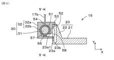
- FIG. 6 is a cross-sectional view in the direction orthogonal to the axis of the first grindstone head including a grindstone main body and a first grindstone shaft unit having a fluid bearing, and corresponds to the IV-IV cross-sectional view of FIG. 5.
- FIG. 5 is a cross-sectional view in the direction orthogonal to the axis of the first grindstone head including a grindstone main body and a first grindstone shaft unit having a fluid bearing, and corresponds to the IV-IV cross-sectional view of FIG. 5.
- FIG. 5 is a sectional view taken along line VV in FIG. 4.
- FIG. FIG. 3 is a side view of the grinding machine when the first grindstone head is located at the retracted position (backward) on the grindstone base. It is a top view of the grinding machine in which the second grindstone shaft unit having a rolling bearing is attached.
- FIG. 3 is a right side view of the grinding machine with a second grindstone shaft unit having a rolling bearing attached thereto.
- FIG. 9 is an exploded perspective view showing a second grindstone that constitutes the grinding machine shown in FIGS. 7 and 8 and includes a grindstone main body and a second grindstone shaft unit having a rolling bearing.
- FIG. 9 is a cross-sectional view in the direction orthogonal to the axis of a second grindstone head including a grindstone main body and a second grindstone shaft unit having a rolling bearing, and corresponds to the XX cross-sectional view of FIG. 9.
- 11 is a sectional view taken along line XI-XI in FIG. 10.
- FIGS. 1 and 2 An overview of the grinding machine 1 of this embodiment will be described with reference to FIGS. 1 and 2.
- the grinding machine 1 rotates the workpiece W and rotates the grinding wheel T while relatively moving the workpiece W and the grinding wheel T.
- the workpiece W is ground by.
- FIGS. 1 and 2 a state in which the grinding wheel T is in contact with a workpiece W is shown.
- the grinding machine 1 is a cylindrical grinding machine, but various configurations such as a cam grinding machine, a surface grinding machine, etc. can be applied.
- the grinding machine 1 is a grinding wheel head traverse type grinding machine, but a table traverse type grinding machine can also be applied.
- the grinding machine 1 in this embodiment is configured so that the following two specifications can be alternatively selected by replacing some of the units.
- the first specification is a specification in which the grinding wheel shaft supporting the grinding wheel T is configured by a fluid bearing using circulating fluid.
- the second specification is a specification in which the grinding wheel shaft supporting the grinding wheel T is constituted by a rolling bearing that does not use circulating fluid.
- the configuration of a grinding machine 1 having specifications including a fluid bearing 32b using circulating fluid will be described with reference to FIGS. 1 and 2.
- FIG. The grinding machine 1 includes a bed 11, a headstock 12, a tailstock 13, a grindstone base 14, a first grindstone 15, a drain unit 16, and a pump unit 17.
- the grinding machine 1 may include a sizing device, a rest device, a grinding wheel correction device, and the like.
- the bed 11 is placed on the installation surface.
- a Z-axis guide 11a extending in the Z-axis direction is formed on the top surface of the bed 11.
- the Z-axis guide 11a is formed on the back side in the X-axis direction (upper side in FIG. 1), which is the back side of the machine.
- the headstock 12 is located on the upper surface of the bed 11 on the front side in the X-axis direction, which is the front side of the machine (bottom side in FIG. 1), and on one end side in the Z-axis direction, which is the left side surface side of the machine (left side in FIG. 1). It is located in The headstock 12 supports one end of the workpiece W in the axial direction, and supports the workpiece W so as to be rotatable around the Z-axis.
- the headstock 12 includes a headstock main body 12a, a main shaft 12b, a motor 12c, and a center member 12d.
- the headstock main body 12a is fixed to the upper surface of the bed 11.
- the main shaft 12b is supported by the headstock main body 12a so as to be rotatable around the Z-axis.
- the motor 12c is provided on the headstock main body 12a and rotationally drives the main shaft 12b.
- the center member 12d is attached to the tip of the main shaft 12b and supports one end of the workpiece W. That is, by rotationally driving the motor 12c, the workpiece W is rotationally driven around the central axis of the workpiece W.
- the headstock 12 supports one end of the workpiece W by the center member 12d, but a chuck may be used instead of the center member 12d.
- the tailstock 13 is arranged on the upper surface of the bed 11 at a position facing the headstock 12 in the Z-axis direction. That is, the tailstock 13 is arranged on the front side in the X-axis direction (lower side in FIG. 1), which is the front of the machine, and on the other end side in the Z-axis direction (right side in FIG. 1), which is the right side of the machine. ing.
- the tailstock 13 supports the other end of the workpiece W in the axial direction, and supports the workpiece W so as to be rotatable around the Z-axis.
- the tailstock 13 includes a tailstock main body 13a, a ram 13b, and a center member 13c.
- the tailstock main body 13a is fixed to the upper surface of the bed 11.
- the ram 13b is provided on the tailstock body 13a so as to be movable in the Z-axis direction. That is, the ram 13b is provided so that its protrusion amount can be changed with respect to the tailstock main body 13a.
- the center member 13c is attached to the tip of the ram 13b and supports the other end of the workpiece W. In this way, the workpiece W is rotatably supported at both ends by the headstock 12 and the tailstock 13. Note that the workpiece W may be cantilevered only by the headstock 12. Further, in the tailstock 13, the tailstock main body 13a may be configured to be movable in the Z-axis direction with respect to the bed 11. In this case, the ram 13b becomes unnecessary.
- the grindstone base 14 (grindstone support member) is disposed on the upper surface of the bed 11 so as to be movable in the Z-axis direction while being guided by the Z-axis guide 11a of the bed 11.
- the grindstone base 14 is configured to be movable via a ball screw device by driving a motor 14a provided on the bed 11.
- the grindstone base 14 may be driven by a linear motor instead of the motor 14a and the ball screw device.
- An X-axis guide 14b extending in the X-axis direction is formed on the upper surface of the grindstone base 14.
- the first whetstone 15 is disposed on the upper surface of the whetstone base 14 so as to be movable in the X-axis direction while being guided by the X-axis guide 14b of the whetstone base 14.
- the first whetstone head 15 is configured to be movable via a ball screw device by driving a motor 15a provided on the whetstone base 14.
- the first grindstone head 15 may be driven by a linear motor instead of the motor 15a and the ball screw device.
- the first whetstone head 15 includes a rotatably provided whetstone wheel T.
- the grinding wheel T is driven by a motor 15b provided on the first grinding wheel head 15, and rotates via a belt 15c.
- the grinding wheel T is composed of a plurality of abrasive grains fixed with a binder.
- the first whetstone head 15 includes a whetstone head body 20 and a first whetstone shaft unit 30.
- the grindstone head main body 20 and the first grindstone shaft unit 30 are formed separately, and are fixed by, for example, bolts (not shown).
- the whetstone main body 20 is supported by the whetstone base 14 so as to be movable in the X-axis direction.
- the grindstone head main body 20 is a member that is made common to both the fluid bearing specification and the rolling bearing specification.
- the first grindstone shaft unit 30 is configured to be detachable from the grindstone main body 20, and rotatably supports the grindstone wheel T.
- the first grindstone unit 30 constitutes a replacement unit dedicated to fluid bearing specifications.
- the first grindstone shaft unit 30 includes a first grindstone shaft 31 and a first unit housing 32.
- the first grinding wheel shaft 31 supports the grinding wheel T.
- the first unit housing 32 is configured to be removably attached to the whetstone head main body 20, and rotatably supports the first whetstone shaft 31. In this embodiment, the first unit housing 32 rotatably supports the first grindstone shaft 31 by a fluid bearing using circulating fluid.
- the drain unit 16 is one of the units used in the grinding machine 1 with fluid bearing specifications. Therefore, the drain unit 16 is removably provided on the grindstone main body 20 and the grindstone base 14, and is a member that receives the circulating fluid discharged from the first grindstone shaft unit 30 via the grindstone main body 20.
- the pump unit 17 is also one of the units used in the grinding machine 1 with fluid bearing specifications.
- the pump unit 17 recovers the circulating fluid from the drain unit 16 via the recovery pipe 17a, and sends out the recovered circulating fluid to the first grindstone shaft unit 30 again via the delivery pipe 17b. That is, the drain unit 16 and the pump unit 17 have a function of circulating the circulating fluid in the fluid bearing of the first grindstone shaft unit 30.
- the recovery pipe 17a and the delivery pipe 17b are configured to be able to follow the movement of the first grindstone head 15.
- the pump unit 17 may be installed adjacent to the bed 11 or may be installed on the top surface of the bed 11.
- first whetstone head 15 includes the whetstone head main body 20 and the first whetstone shaft unit 30.
- the grindstone head main body 20 includes a base portion 21 and an upright portion 22.
- the base portion 21 and the upright portion 22 are integrally formed.
- the base portion 21 and the upright portion 22 are integrally formed by casting.
- the base portion 21 and the upright portion 22 may be molded separately and then fixed together.
- the base portion 21 has a seat surface 21a on the upper surface. Further, the base portion 21 is supported by the grindstone base 14 so as to be movable in the X-axis direction.
- the base portion 21 is formed into a rectangular flat plate shape.
- the base portion 21 can be formed into any shape as long as it has a seat surface 21a at least on the front side in the X-axis direction.
- the seat surface 21a of the base part 21 is a surface on the extension line of the area where the standing part 22 does not exist on the upper surface of the base part 21. Thus, it becomes a virtual surface that constitutes a boundary between the base portion 21 and the upright portion 22.
- the upright portion 22 is erected upward from the seat surface 21a of the base portion 21. Specifically, the upright portion 22 is erected from the seat surface 21a of the base portion 21 at the front in the X-axis direction.
- the upright portion 22 has a mounting surface 22a for mounting the first grindstone shaft unit 30 on a surface extending in the vertical direction, that is, on the front surface in the X-axis direction.
- the upright portion 22 is configured to resist horizontal grinding resistance that the first grindstone shaft unit 30 receives when grinding the workpiece W with the grindstone T.
- the upright portion 22 includes a plate portion 22b extending vertically from the front edge portion of the seat surface 21a of the base portion 21, and a plurality of ribs 22c on the back surface of the plate portion 22b.
- the plurality of ribs 22c are configured such that the depth length increases from the upper end toward the lower end.
- the plurality of ribs 22c are formed of a right triangle with the apex located at the upper end, a trapezoid whose upper side is shorter than the lower side, or the like.
- a discharge connection channel 23 for circulating circulating fluid is formed in the grindstone head main body 20, spanning the base portion 21 and the upright portion 22.
- the discharge connection channel 23 has an inlet 23a1 formed on the mounting surface 22a of the upright portion 22, and an outlet 23c1 formed on the side surface of the base portion 21.
- the discharge connection flow path 23 includes a first flow path 23a, a second flow path 23b, and a third flow path 23c.
- the first flow path 23a is formed in the upright portion 22, and is formed toward the back side (horizontal direction) in the X-axis direction from the inlet 23a1.
- the second flow path 23b is connected to the first flow path 23a and is formed to extend in the Y-axis direction (vertical direction).
- the second flow path 23b is formed spanning from the upright portion 22 to the base portion 21. Further, from the viewpoint of processing, the second flow path 23b is closed at the upper end by a lid member.
- the third flow path 23c is formed to extend in the Z-axis direction (horizontal direction) from the lower end of the second flow path 23b to the outlet 23c1 on the side surface of the base portion 21.
- the discharge connection channel 23 is formed such that the channel cross-sectional area decreases from the inlet 23a1 to the outlet 23c1. This configuration allows the circulating fluid to naturally flow easily from the inlet 23a1 toward the outlet 23c1.
- the flow path shape of the discharge connection flow path 23 can be any shape as long as it can freely flow from the inlet 23a1 to the outlet 23c1 by gravity.
- the first grindstone shaft unit 30 includes a first grindstone shaft 31 and a first unit housing 32.
- the first grinding wheel shaft 31 supports the grinding wheel T, as described above.
- the first unit housing 32 rotatably supports the first grindstone shaft 31 by a fluid bearing 32b using circulating fluid.
- the first unit housing 32 includes a first housing body 32a and a plurality of fluid bearings 32b.
- the first housing body 32a has a through hole 51 through which the first grindstone shaft 31 can be inserted.
- the first housing main body 32a further includes an attached surface 52 that contacts the mounting surface 22a of the upright portion 22 of the grindstone main body 20, and a collar portion 53 that is placed on the upper end surface of the upright portion 22.
- the flange portion 53 is placed on the upper end surface of the upright portion 22 to position the first unit housing 32 in the vertical direction.
- two fluid bearings 32b are arranged at one end and the other end of the through hole 51 of the first housing body 32a.
- the fluid bearing 32b supports the outer circumferential surface of the first grindstone shaft 31 via the circulating fluid on its inner circumferential surface.
- a supply channel 54 for supplying circulating fluid to the fluid bearing 32b is formed in the first housing body 32a.
- An inlet 55 of the supply channel 54 is formed on the upper surface of the first housing body 32a, and is connected to the delivery pipe 17b. Therefore, the circulating fluid is supplied to the supply channel 54 from the delivery pipe 17b.
- discharge passages 56 and 57 for discharging circulating fluid from the fluid bearing 32b are formed in the first housing body 32a.
- the first discharge channel 56 is formed from each of the two fluid bearings 32b toward the center of the first housing body 32a in the Z-axis direction.
- the second discharge passage 57 is formed near the center of the first housing body 32a in the Z-axis direction, and connects the first discharge passage 56 and the outlet 58 formed on the attached surface 52.
- the second discharge flow path 57 is formed in a range extending from the lower region of the through hole 51 to the outlet 58.
- the second discharge channel 57 collects the circulating fluid discharged from the two fluid bearings 32b, and is formed to have a sufficiently large space to maintain good circulation of the circulating fluid in the fluid bearings 32b. ing.
- the outlet 58 of the second discharge flow path 57 is formed into an oval shape whose longitudinal direction is the vertical direction, and has a shape that facilitates the formation of a space above when the circulating fluid flows.
- the inlet 23a1 of the discharge connection flow path 23 formed in the grindstone head main body 20 is also formed in an oval shape whose longitudinal direction is the vertical direction.
- the inlet 23a1 of the discharge connection passage 23 of the grindstone main body 20 is formed to face the entire outlet 58 of the discharge passage 57 of the first housing body 32a, and It is formed larger than the outlet 58.
- a sealing member (not shown) is arranged around the outlet 58 of the second discharge channel 57, and is in contact with the mounting surface 22a of the grindstone main body 20 and the mounting surface 52 of the first housing main body 32a. Therefore, the sealing member exhibits a sealing function when the circulating fluid flows from the second discharge passage 57 to the discharge connection passage 23 of the grindstone main body 20.
- the first housing main body 32a of the first unit housing 32 is formed with discharge passages 56 and 57 for discharging the circulating fluid from the fluid bearing 32b.
- the discharge connection channel 23 of the base portion 21 of the grindstone main body 20 is configured to allow circulating fluid to flow between the discharge channels 56 and 57 of the first unit housing 32. Therefore, the circulating fluid discharged from the fluid bearing 32b flows to the outlet 23c1 on the side surface of the base portion 21 of the grindstone main body 20.
- the drain unit 16 is connected to the discharge connection flow path 23 and functions as a member that receives the circulating fluid discharged from the outlet 23c1 of the discharge connection flow path 23. The drain unit 16 then circulates the circulating fluid received from the discharge connection flow path 23 to the recovery pipe 17a connected to the pump unit 17.
- the whetstone main body 20 is configured to be movable in the X-axis direction on the upper surface of the whetstone base 14. Therefore, as shown in FIGS. 1 and 2, the drain unit 16 is provided on the side surface of the whetstone main body 20 and the side surface of the whetstone base 14, and is connected to both the whetstone main body 20 and the whetstone base 14. It is configured to be detachable. Furthermore, as shown in FIGS. 1 and 6, since the grinding wheel head main body 20 moves in the X-axis direction with respect to the grinding wheel head base 14, the drain unit 16 can move the grinding wheel head main body 20 relative to the grinding wheel head base 14 by It has a corresponding length adjustment mechanism.
- the drain unit 16 includes a first gutter 41, a second gutter 42, and a length adjustment pipe 43.
- the first gutter 41 is provided on the side surface of the grindstone head main body 20. Therefore, the first gutter 41 moves integrally with the grindstone head main body 20.
- the first gutter 41 receives the circulating fluid discharged from the outlet 23c1 of the discharge connection channel 23 of the grindstone head main body 20.
- the first gutter 41 is configured to be detachable from the whetstone head main body 20.
- the second gutter 42 is provided on the side surface of the grindstone base 14. Therefore, the second gutter 42 moves integrally with the grindstone base 14.
- the second gutter 42 is connected to a recovery pipe 17a that is connected to the pump unit 17.
- the second gutter 42 is configured to be detachable from the grindstone base 14.
- the length adjustment pipe 43 connects the first gutter 41 and the second gutter 42.
- the length adjustment pipe 43 is connected to the first gutter 41 and is configured to be inserted through an opening formed in the second gutter 42. Therefore, the length adjustment pipe 43 moves integrally with the first gutter 41, but moves relative to the second gutter 42.
- a metal or resin pipe with a fixed shape is used for the length adjustment pipe 43. In this case, as the grindstone head main body 20 moves, the amount of insertion of the tip end side of the length adjustment pipe 43 into the second gutter 42 changes.
- the length adjustment pipe 43 may be formed in a bellows shape that can be expanded and contracted in the length direction.
- the configuration of the grinding machine 2 having specifications including a rolling bearing 132b that does not use circulating fluid will be described with reference to FIGS. 7 and 8.
- the grinding machine 2 includes a bed 11, a headstock 12, a tailstock 13, a grindstone base 14, and a second grindstone 115.
- the bed 11, headstock 12, tailstock 13, and grindstone base 14 are similar in configuration to the grinding machine 1.
- the grinding machine 1 may include a sizing device, a rest device, a grinding wheel correction device, and the like. Note that the grinding machine 2 does not include a drain unit and a pump unit.
- the second whetstone head 115 is disposed on the upper surface of the whetstone base 14 so as to be movable in the X-axis direction while being guided by the X-axis guide 14b of the whetstone base 14.
- the second whetstone head 115 is configured to be movable via a ball screw device by driving a motor 15a provided on the whetstone base 14.
- the second grindstone head 115 may be driven by a linear motor instead of the motor 15a and the ball screw device.
- the second whetstone head 115 includes a rotatably provided whetstone wheel T.
- the grinding wheel T is driven by a motor 15b provided on the second grinding wheel head 115, and rotates via a belt 15c.
- the second whetstone head 115 includes a whetstone head main body 20 and a second whetstone shaft unit 130.
- the grindstone head main body 20 and the second grindstone shaft unit 130 are formed separately, and are fixed by, for example, bolts (not shown).
- the grinding wheel head main body 20 is a member that is shared with the grinding wheel head main body 20 that constitutes the grinding machine 1 having a fluid bearing specification.
- the second grindstone shaft unit 130 is configured to be detachable from the grindstone main body 20, and rotatably supports the grindstone wheel T.
- the second grindstone shaft unit 130 constitutes a replacement unit dedicated to rolling bearing specifications.
- the second grindstone shaft unit 130 includes a second grindstone shaft 131 and a second unit housing 132.
- the second grinding wheel shaft 131 supports the grinding wheel T.
- the second unit housing 132 is configured to be removably attached to the whetstone head main body 20, and rotatably supports the second whetstone shaft 131. In this embodiment, the second unit housing 132 rotatably supports the second grindstone shaft 131 by a rolling bearing that does not use circulating fluid.
- the second whetstone head 115 includes the whetstone head main body 20 and the second whetstone shaft unit 130, as described above. Since the whetstone head body 20 is a member shared with the whetstone head body 20 constituting the first whetstone head 15, it includes a base portion 21 and an upright portion 22. The base portion 21 and the upright portion 22 are integrally formed. However, the base portion 21 and the upright portion 22 may be molded separately and then fixed together. The detailed configurations of the base portion 21 and the upright portion 22 are as described above.
- the second grindstone shaft unit 130 includes a second grindstone shaft 131 and a second unit housing 132.
- the second grinding wheel shaft 131 supports the grinding wheel T, as described above.
- the second unit housing 132 rotatably supports the second grindstone shaft 131 by a rolling bearing 132b that does not use circulating fluid.
- the second unit housing 132 has a second housing main body 132a and a plurality of rolling bearings 132b.
- the second housing main body 132a has a through hole 151 through which the second grindstone shaft 131 can be inserted.
- the outer shape of the second housing body 132a is formed substantially the same as the first housing body 32a described above. Therefore, the second housing main body 132a includes an attached surface 152 that contacts the mounting surface 22a of the upright portion 22 of the grindstone main body 20, and a collar portion 153 that is placed on the upper end surface of the upright portion 22.
- the flange portion 153 is placed on the upper end surface of the upright portion 22 to position the second unit housing 132 in the vertical direction.
- a plurality of rolling bearings 132b are arranged at one end and the other end of the through hole 151 of the second housing body 132a.
- the rolling bearing 132b has a configuration that does not use circulating fluid. For example, grease or the like is prefilled inside the rolling bearing 132b to ensure lubricity.
- the second housing body 132a of the second unit housing 132 does not have a circulating fluid supply channel and a discharge channel formed in the rolling bearing 132b. Therefore, in the second housing body 132a, the areas of the supply passage 54 and the discharge passages 56 and 57 in the first housing body 32a are filled with a material (for example, cast iron) forming the second housing body 132a. . Therefore, the second housing body 132a does not have an inlet 55 and an outlet 58.
- the discharge connection flow path 23 of the grindstone main body 20 is closed by the second housing main body 132a of the second unit housing 132. configured. That is, the inlet 23a1 of the discharge connection channel 23 formed in the grindstone main body 20 is closed by the attached surface 152 of the second housing main body 132a. On the other hand, the outlet 23c1 of the discharge connection flow path 23 is closed by a cover 121 as a separate member. In this way, by closing both openings of the discharge connection channel 23 in the shared grindstone head main body 20, it is possible to suppress dust from entering the discharge connection channel 23.
- the grinding machines 1 and 2 have a grinding wheel head 15 and 115 separated into a grinding wheel head main body 20 and a grinding wheel shaft unit 30 and 130.
- the first grindstone shaft unit 30 having a fluid bearing 32b using circulating fluid and the second grindstone shaft unit 130 having a rolling bearing 132b not using circulating fluid are selectively selected. configured to be possible. That is, as shown in FIG. 1, when the first grindstone shaft unit 30 is attached to the grindstone main body 20, the grinding machine 1 is designed to have a fluid bearing 32b using circulating fluid.
- FIG. 1 when the first grindstone shaft unit 30 is attached to the grindstone main body 20, the grinding machine 1 is designed to have a fluid bearing 32b using circulating fluid.
- the grinding machine 2 when the second grindstone shaft unit 130 is attached to the grindstone main body 20, the grinding machine 2 is designed to have a rolling bearing 132b that does not use circulating fluid. In this way, in the grindstone heads 15 and 115, the grindstone main body 20 is made common and the grindstone shaft units 30 and 130 are configured to be replaceable, so that no matter which specification is adopted, the grinding machines 1 and 2 As a result, lower costs can be achieved.
- the user can purchase the second grinding wheel shaft unit 130 separately, thereby obtaining a rolling bearing that does not use circulating fluid. It can be replaced with the grinding machine 2 having the specifications of 132b. Therefore, the degree of freedom of selection increases for the user.
- the grindstone head main body 20 is configured to allow circulation of circulating fluid between the fluid bearing 32b of the first grindstone shaft unit 30 when the first grindstone shaft unit 30 is attached. It has a passage 23.
- the discharge connection channel 23 is not used.
- the discharge connection channel 23 is configured to be closed by the second unit housing 132 of the second grindstone shaft unit 130. Therefore, when the discharge connection passage 23 is not in use, the second grindstone shaft unit 130 can prevent dust from entering the discharge connection passage 23, and maintain the discharge connection passage 23 in a good condition. can do. Therefore, regardless of whether the fluid bearing 32b using circulating fluid or the rolling bearing 132b not using circulating fluid is employed, the costs of the grinding machines 1 and 2 can be reduced.
- the grindstone head main body 20 is formed with the discharge connection channel 23 configured to allow circulating fluid to flow between the discharge channels 56 and 57 of the first grindstone shaft unit 30.
- the discharge connection channel 23 is formed in the grindstone head main body 20, it is possible to easily form a discharge path for the circulating fluid. Even if the grindstone main body 20 has the discharge connection flow path 23, by standardizing the grindstone main body 20 even for the specifications of the rolling bearing 132b that does not use circulating fluid, the replacement unit part can be made smaller. can do.
- the grinding machine 1 includes a drain unit 16 that is configured to be detachable from the grinding wheel head main body 20, is connected to the discharge connection channel 23, and receives the circulating fluid discharged from the discharge connection channel 23.
- a drain unit 16 By making the drain unit 16 also removable, it is possible to reduce the size and cost of the grinding machine 2 that uses a rolling bearing 132b that does not use circulating fluid.
- the grinding machines 1 and 2 include a grindstone base 14 that movably supports the grindstone main body 20.
- the drain unit 16 is configured to be detachable from the grindstone main body 20 and the grindstone base 14, and has a length adjustment mechanism 43 corresponding to the moving distance of the grindstone main body 20 with respect to the grindstone base 14. Therefore, even if the whetstone main body 20 is configured to move relative to the whetstone base 14, a part of the drain unit 16 can be attached to the whetstone base 14 by the length adjustment mechanism 43 of the drain unit 16. . As a result, the circulating fluid can be discharged to the position of the grindstone base 14.
- the drain unit 16 is configured to be removably attached to the grindstone main body 20, and includes a first gutter 41 that receives circulating fluid discharged from the discharge connection channel 23 of the grindstone main body 20, and a grindstone base. a second gutter 42 that is configured to be detachably attached to the pump unit 14 and connected to the pump unit 17; and a length adjustment pipe 43 that connects between the first gutter 41 and the second gutter 42 and constitutes a length adjustment mechanism. Equipped with. With such a configuration, the length adjustment mechanism can be easily and reliably realized.
- the inlet 23a1 of the discharge connection passage 23 of the grindstone main body 20 is formed to face the entire outlet 58 of the discharge passage 56, 57 of the first unit housing 32, and the discharge passage 56, It is formed larger than the outlet 58 of 57.
- the flow of the circulating fluid in the discharge channels 56 and 57 of the first grindstone shaft unit 30 can be prevented from being obstructed.
- the fluid bearing 32b can continue to exert the desired supporting force.
- the discharge connection channel 23 of the grindstone head main body 20 is formed such that the channel area decreases from the inlet 23a1 to the outlet 23c1. With such a configuration, a free flow of the circulating fluid can be formed in the discharge connection channel 23 of the grindstone main body 20 from the inlet 23a1 toward the outlet 23c1.
- the grindstone head main body 20 also includes a base portion 21 having a seat surface 21a on the upper surface, and a grindstone shaft unit 30, 130 on a vertically extending surface that is erected upward from the seat surface 21a of the base portion 21.
- an upright portion 22 having a mounting surface 22a for mounting the grinding wheel T, and configured to resist the horizontal grinding resistance that the grinding wheel shaft units 30, 130 receive when grinding the workpiece W with the grinding wheel T; Equipped with The inlet 23a1 of the discharge connection flow path 23 is formed on the mounting surface 22a of the upright portion 22, and the outlet 23c1 of the discharge connection flow path 23 is formed on the side surface of the base portion 21.
- 23 is formed astride the upright portion 22 and the base portion 21 .
- the weight of the whetstone head main body 20 can be reduced. Furthermore, by forming the discharge connection flow path 23 across the base portion 21 and the upright portion 22, the upstream position of the discharge connection flow path 23 can be positioned upward, and the downstream position can be positioned downward. . As a result, it becomes possible to freely circulate the circulating fluid in the discharge connecting flow path 23.
- the first unit housing 32 has an inlet 55 for the supply flow path 54 formed on the upper surface, and an outlet 58 for the discharge flow paths 56 and 57 on the attached surface 52 that comes into contact with the grindstone main body 20.
- the discharge connection channel 23 of the grindstone main body 20 is configured to connect only to the discharge channels 56 and 57 in the first unit housing 32.
- the supply flow path 54 is connected to the pump unit 17 through, for example, separate piping.
- the discharge connection channel 23 is formed in the grindstone head main body 20, and the circulating fluid is configured to be able to flow between the discharge channels 56 and 57 of the first unit housing 32.
- a supply connection channel may be further formed in the grindstone head main body 20 so that the circulating fluid can flow between it and the supply channel 54 of the first unit housing 32.
- the grindstone head main body 20 may not be provided with the discharge connection flow path 23 but may be provided with a supply connection flow path.
- the grinding machines 1 and 2 are of the grindstone traverse type.
- the whetstone base 14 functions as a whetstone support member that supports the whetstone heads 15 and 115.
- the grinding machines 1 and 2 can also be of the table traverse type.
- the bed 11 serves as the grindstone support member that supports the grindstone heads 15 and 115.
Landscapes
- Engineering & Computer Science (AREA)
- Mechanical Engineering (AREA)
- Constituent Portions Of Griding Lathes, Driving, Sensing And Control (AREA)
Priority Applications (2)
| Application Number | Priority Date | Filing Date | Title |
|---|---|---|---|
| PCT/JP2022/011633 WO2023175723A1 (ja) | 2022-03-15 | 2022-03-15 | 研削盤 |
| JP2024507255A JP7816488B2 (ja) | 2022-03-15 | 2022-03-15 | 研削盤 |
Applications Claiming Priority (1)
| Application Number | Priority Date | Filing Date | Title |
|---|---|---|---|
| PCT/JP2022/011633 WO2023175723A1 (ja) | 2022-03-15 | 2022-03-15 | 研削盤 |
Publications (1)
| Publication Number | Publication Date |
|---|---|
| WO2023175723A1 true WO2023175723A1 (ja) | 2023-09-21 |
Family
ID=88022487
Family Applications (1)
| Application Number | Title | Priority Date | Filing Date |
|---|---|---|---|
| PCT/JP2022/011633 Ceased WO2023175723A1 (ja) | 2022-03-15 | 2022-03-15 | 研削盤 |
Country Status (2)
| Country | Link |
|---|---|
| JP (1) | JP7816488B2 (https=) |
| WO (1) | WO2023175723A1 (https=) |
Citations (3)
| Publication number | Priority date | Publication date | Assignee | Title |
|---|---|---|---|---|
| JPS59192410A (ja) * | 1983-04-12 | 1984-10-31 | Toyoda Mach Works Ltd | 回転刃具を備えた加工装置 |
| JPS63216673A (ja) * | 1987-03-03 | 1988-09-08 | Citizen Watch Co Ltd | 外周回転型スピンドル |
| JPH0671046U (ja) * | 1993-03-10 | 1994-10-04 | 豊田工機株式会社 | 砥石台における軸受油回収装置 |
-
2022
- 2022-03-15 JP JP2024507255A patent/JP7816488B2/ja active Active
- 2022-03-15 WO PCT/JP2022/011633 patent/WO2023175723A1/ja not_active Ceased
Patent Citations (3)
| Publication number | Priority date | Publication date | Assignee | Title |
|---|---|---|---|---|
| JPS59192410A (ja) * | 1983-04-12 | 1984-10-31 | Toyoda Mach Works Ltd | 回転刃具を備えた加工装置 |
| JPS63216673A (ja) * | 1987-03-03 | 1988-09-08 | Citizen Watch Co Ltd | 外周回転型スピンドル |
| JPH0671046U (ja) * | 1993-03-10 | 1994-10-04 | 豊田工機株式会社 | 砥石台における軸受油回収装置 |
Also Published As
| Publication number | Publication date |
|---|---|
| JPWO2023175723A1 (https=) | 2023-09-21 |
| JP7816488B2 (ja) | 2026-02-18 |
Similar Documents
| Publication | Publication Date | Title |
|---|---|---|
| US6599066B1 (en) | Rotating shaft device and machine tool | |
| US7101269B2 (en) | Cylindrical grinding machine | |
| JP3801474B2 (ja) | 工作機械 | |
| JP5285314B2 (ja) | 工作機械 | |
| JP4893812B2 (ja) | ガラス板の研削方法及びその装置 | |
| US20130183890A1 (en) | Processing apparatus | |
| WO2023175723A1 (ja) | 研削盤 | |
| JP2003266306A (ja) | ガラス板の研削方法及びその装置 | |
| JP5042356B2 (ja) | 回転式通液継手及び研削装置 | |
| JP2010042488A (ja) | ワーク受け及びこれを備えた研削盤 | |
| JP2022066848A (ja) | 工作機械の主軸装置のドレン構造 | |
| JP5132501B2 (ja) | センタレス研削盤 | |
| JP4710295B2 (ja) | 工作機械 | |
| CN107962450B (zh) | 排液机构以及具备排液机构的机床 | |
| KR101540723B1 (ko) | 연삭기의 가공물 자동공급장치 | |
| CN1765575B (zh) | 无心磨床 | |
| JP2006077798A (ja) | 流体軸受及び流体軸受を用いた研削盤 | |
| JP7247832B2 (ja) | 回転軸部材支持装置及び研削盤 | |
| JP2011235403A (ja) | 工作機械の軸装置 | |
| US20060135043A1 (en) | Grinding method and grinding machine | |
| JP4192605B2 (ja) | 円筒研削盤 | |
| JP2005001037A (ja) | 研削盤 | |
| JP2023087899A (ja) | スピンドルユニット | |
| CN223236049U (zh) | 一种用于数控磨床的加工冷却系统 | |
| CN214817406U (zh) | 能实现充分冷却的数控精密加工用磨床 |
Legal Events
| Date | Code | Title | Description |
|---|---|---|---|
| 121 | Ep: the epo has been informed by wipo that ep was designated in this application |
Ref document number: 22932007 Country of ref document: EP Kind code of ref document: A1 |
|
| WWE | Wipo information: entry into national phase |
Ref document number: 2024507255 Country of ref document: JP |
|
| NENP | Non-entry into the national phase |
Ref country code: DE |
|
| 122 | Ep: pct application non-entry in european phase |
Ref document number: 22932007 Country of ref document: EP Kind code of ref document: A1 |