WO2023171649A1 - 車両用検出装置 - Google Patents
車両用検出装置 Download PDFInfo
- Publication number
- WO2023171649A1 WO2023171649A1 PCT/JP2023/008503 JP2023008503W WO2023171649A1 WO 2023171649 A1 WO2023171649 A1 WO 2023171649A1 JP 2023008503 W JP2023008503 W JP 2023008503W WO 2023171649 A1 WO2023171649 A1 WO 2023171649A1
- Authority
- WO
- WIPO (PCT)
- Prior art keywords
- receiving coil
- displacement
- detection
- section
- coil
- Prior art date
Links
- 238000001514 detection method Methods 0.000 title claims abstract description 193
- 238000006073 displacement reaction Methods 0.000 claims abstract description 127
- 238000005096 rolling process Methods 0.000 claims abstract description 7
- 230000005284 excitation Effects 0.000 claims description 59
- 238000012545 processing Methods 0.000 claims description 23
- 229910052751 metal Inorganic materials 0.000 claims description 7
- 239000002184 metal Substances 0.000 claims description 7
- 230000003321 amplification Effects 0.000 claims description 5
- 238000003199 nucleic acid amplification method Methods 0.000 claims description 5
- 238000010586 diagram Methods 0.000 description 23
- 239000000758 substrate Substances 0.000 description 22
- 238000004364 calculation method Methods 0.000 description 12
- 238000013459 approach Methods 0.000 description 11
- 230000008859 change Effects 0.000 description 8
- 238000004804 winding Methods 0.000 description 8
- 230000007704 transition Effects 0.000 description 7
- 230000007423 decrease Effects 0.000 description 6
- 230000004907 flux Effects 0.000 description 6
- 238000000034 method Methods 0.000 description 6
- 238000003860 storage Methods 0.000 description 5
- 230000002093 peripheral effect Effects 0.000 description 4
- 230000004048 modification Effects 0.000 description 3
- 238000012986 modification Methods 0.000 description 3
- 230000001360 synchronised effect Effects 0.000 description 3
- XEEYBQQBJWHFJM-UHFFFAOYSA-N Iron Chemical compound [Fe] XEEYBQQBJWHFJM-UHFFFAOYSA-N 0.000 description 2
- 230000015572 biosynthetic process Effects 0.000 description 2
- 238000004590 computer program Methods 0.000 description 2
- 230000000694 effects Effects 0.000 description 2
- 230000006870 function Effects 0.000 description 2
- 230000001939 inductive effect Effects 0.000 description 2
- 238000003780 insertion Methods 0.000 description 2
- 230000037431 insertion Effects 0.000 description 2
- 238000004519 manufacturing process Methods 0.000 description 2
- HBBGRARXTFLTSG-UHFFFAOYSA-N Lithium ion Chemical compound [Li+] HBBGRARXTFLTSG-UHFFFAOYSA-N 0.000 description 1
- 229910052782 aluminium Inorganic materials 0.000 description 1
- XAGFODPZIPBFFR-UHFFFAOYSA-N aluminium Chemical compound [Al] XAGFODPZIPBFFR-UHFFFAOYSA-N 0.000 description 1
- 239000004020 conductor Substances 0.000 description 1
- 229910052742 iron Inorganic materials 0.000 description 1
- 229910001416 lithium ion Inorganic materials 0.000 description 1
- 239000007769 metal material Substances 0.000 description 1
- 229910001172 neodymium magnet Inorganic materials 0.000 description 1
- 229910052755 nonmetal Inorganic materials 0.000 description 1
- 230000004044 response Effects 0.000 description 1
- 230000035945 sensitivity Effects 0.000 description 1
- 229920003002 synthetic resin Polymers 0.000 description 1
- 239000000057 synthetic resin Substances 0.000 description 1
Images


Classifications
-
- F—MECHANICAL ENGINEERING; LIGHTING; HEATING; WEAPONS; BLASTING
- F16—ENGINEERING ELEMENTS AND UNITS; GENERAL MEASURES FOR PRODUCING AND MAINTAINING EFFECTIVE FUNCTIONING OF MACHINES OR INSTALLATIONS; THERMAL INSULATION IN GENERAL
- F16C—SHAFTS; FLEXIBLE SHAFTS; ELEMENTS OR CRANKSHAFT MECHANISMS; ROTARY BODIES OTHER THAN GEARING ELEMENTS; BEARINGS
- F16C41/00—Other accessories, e.g. devices integrated in the bearing not relating to the bearing function as such
- F16C41/007—Encoders, e.g. parts with a plurality of alternating magnetic poles
-
- B—PERFORMING OPERATIONS; TRANSPORTING
- B60—VEHICLES IN GENERAL
- B60B—VEHICLE WHEELS; CASTORS; AXLES FOR WHEELS OR CASTORS; INCREASING WHEEL ADHESION
- B60B27/00—Hubs
- B60B27/0047—Hubs characterised by functional integration of other elements
- B60B27/0068—Hubs characterised by functional integration of other elements the element being a sensor
-
- F—MECHANICAL ENGINEERING; LIGHTING; HEATING; WEAPONS; BLASTING
- F16—ENGINEERING ELEMENTS AND UNITS; GENERAL MEASURES FOR PRODUCING AND MAINTAINING EFFECTIVE FUNCTIONING OF MACHINES OR INSTALLATIONS; THERMAL INSULATION IN GENERAL
- F16C—SHAFTS; FLEXIBLE SHAFTS; ELEMENTS OR CRANKSHAFT MECHANISMS; ROTARY BODIES OTHER THAN GEARING ELEMENTS; BEARINGS
- F16C19/00—Bearings with rolling contact, for exclusively rotary movement
- F16C19/02—Bearings with rolling contact, for exclusively rotary movement with bearing balls essentially of the same size in one or more circular rows
- F16C19/04—Bearings with rolling contact, for exclusively rotary movement with bearing balls essentially of the same size in one or more circular rows for radial load mainly
- F16C19/08—Bearings with rolling contact, for exclusively rotary movement with bearing balls essentially of the same size in one or more circular rows for radial load mainly with two or more rows of balls
-
- F—MECHANICAL ENGINEERING; LIGHTING; HEATING; WEAPONS; BLASTING
- F16—ENGINEERING ELEMENTS AND UNITS; GENERAL MEASURES FOR PRODUCING AND MAINTAINING EFFECTIVE FUNCTIONING OF MACHINES OR INSTALLATIONS; THERMAL INSULATION IN GENERAL
- F16C—SHAFTS; FLEXIBLE SHAFTS; ELEMENTS OR CRANKSHAFT MECHANISMS; ROTARY BODIES OTHER THAN GEARING ELEMENTS; BEARINGS
- F16C19/00—Bearings with rolling contact, for exclusively rotary movement
- F16C19/02—Bearings with rolling contact, for exclusively rotary movement with bearing balls essentially of the same size in one or more circular rows
- F16C19/14—Bearings with rolling contact, for exclusively rotary movement with bearing balls essentially of the same size in one or more circular rows for both radial and axial load
- F16C19/18—Bearings with rolling contact, for exclusively rotary movement with bearing balls essentially of the same size in one or more circular rows for both radial and axial load with two or more rows of balls
-
- F—MECHANICAL ENGINEERING; LIGHTING; HEATING; WEAPONS; BLASTING
- F16—ENGINEERING ELEMENTS AND UNITS; GENERAL MEASURES FOR PRODUCING AND MAINTAINING EFFECTIVE FUNCTIONING OF MACHINES OR INSTALLATIONS; THERMAL INSULATION IN GENERAL
- F16C—SHAFTS; FLEXIBLE SHAFTS; ELEMENTS OR CRANKSHAFT MECHANISMS; ROTARY BODIES OTHER THAN GEARING ELEMENTS; BEARINGS
- F16C41/00—Other accessories, e.g. devices integrated in the bearing not relating to the bearing function as such
-
- G—PHYSICS
- G01—MEASURING; TESTING
- G01B—MEASURING LENGTH, THICKNESS OR SIMILAR LINEAR DIMENSIONS; MEASURING ANGLES; MEASURING AREAS; MEASURING IRREGULARITIES OF SURFACES OR CONTOURS
- G01B11/00—Measuring arrangements characterised by the use of optical techniques
- G01B11/26—Measuring arrangements characterised by the use of optical techniques for measuring angles or tapers; for testing the alignment of axes
- G01B11/275—Measuring arrangements characterised by the use of optical techniques for measuring angles or tapers; for testing the alignment of axes for testing wheel alignment
-
- G—PHYSICS
- G01—MEASURING; TESTING
- G01L—MEASURING FORCE, STRESS, TORQUE, WORK, MECHANICAL POWER, MECHANICAL EFFICIENCY, OR FLUID PRESSURE
- G01L1/00—Measuring force or stress, in general
-
- G—PHYSICS
- G01—MEASURING; TESTING
- G01L—MEASURING FORCE, STRESS, TORQUE, WORK, MECHANICAL POWER, MECHANICAL EFFICIENCY, OR FLUID PRESSURE
- G01L5/00—Apparatus for, or methods of, measuring force, work, mechanical power, or torque, specially adapted for specific purposes
-
- B—PERFORMING OPERATIONS; TRANSPORTING
- B60—VEHICLES IN GENERAL
- B60B—VEHICLE WHEELS; CASTORS; AXLES FOR WHEELS OR CASTORS; INCREASING WHEEL ADHESION
- B60B35/00—Axle units; Parts thereof ; Arrangements for lubrication of axles
- B60B35/02—Dead axles, i.e. not transmitting torque
-
- F—MECHANICAL ENGINEERING; LIGHTING; HEATING; WEAPONS; BLASTING
- F16—ENGINEERING ELEMENTS AND UNITS; GENERAL MEASURES FOR PRODUCING AND MAINTAINING EFFECTIVE FUNCTIONING OF MACHINES OR INSTALLATIONS; THERMAL INSULATION IN GENERAL
- F16C—SHAFTS; FLEXIBLE SHAFTS; ELEMENTS OR CRANKSHAFT MECHANISMS; ROTARY BODIES OTHER THAN GEARING ELEMENTS; BEARINGS
- F16C2326/00—Articles relating to transporting
- F16C2326/01—Parts of vehicles in general
- F16C2326/02—Wheel hubs or castors
Definitions
- the present disclosure relates to a vehicle detection device.
- a bearing unit that rotatably supports a hub fixed to a wheel with respect to a vehicle body.
- the bearing unit includes an outer ring fixed to the vehicle body, an inner ring fixed to the hub, and rolling elements between the outer ring and the inner ring.
- Patent Document 1 describes a detection ring provided on the inner peripheral side of an inner ring and fixed to a hub, and a displacement sensor unit.
- the detection ring includes a cylindrical portion and a bent portion bent radially outward from an axial end of the cylindrical portion.
- the distal end portion of the displacement sensor unit is arranged on the inner peripheral side of the inner ring.
- a displacement measuring element is provided at the tip of the displacement sensor unit, facing the bend in the axial direction of the bearing unit.
- the bent portion Since the bent portion is provided inside the bearing unit, the displacement of the bent portion in the axial direction when force is applied to the wheel is small. In this case, there is a concern that displacement detection accuracy may deteriorate.
- the main objective of the present disclosure is to provide a vehicle detection device that can improve displacement detection accuracy.
- the present disclosure includes a base portion fixed to a vehicle body;
- a bearing having an outer ring member, an inner ring member, and a rolling element provided between the outer ring member and the inner ring member, and rotatably supporting a wheel of the vehicle with respect to the base portion,
- One of the outer ring member and the inner ring member, a first bearing member, is fixed to the wheel, and the other, a second bearing member, is fixed to the base part, a disc-shaped detection rotating part that is provided to rotate integrally with the first bearing member and extends radially outward of the bearing with respect to the first bearing member;
- the base portion is provided at a position away from the bearing in the radial direction and facing the detection rotation unit in the axial direction of the bearing, in a non-contact state with the detection rotation unit, and a displacement detection section that outputs a signal corresponding to the displacement of the detection rotation section in the axial direction.
- the detection rotating part is provided so as to rotate integrally with the first bearing member that constitutes the bearing. Therefore, the detection rotating part rotates integrally with the wheel fixed to the first bearing member.
- the displacement detection section is provided in the base section at a position radially away from the bearing and facing the detection rotating section in the axial direction. For this reason, it is possible to increase the change in the output signal (for example, the amplitude of the output signal) of the displacement detection section in response to a change in the axial displacement of the detection rotating section, for example, compared to a configuration in which the displacement detection section is provided within the bearing. I can do it. Thereby, the accuracy in detecting displacement by the displacement detection unit can be increased, and for example, the accuracy in calculating lateral force based on the detected displacement can be increased.
- FIG. 1 is a longitudinal sectional view of a wheel according to a first embodiment
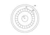
- FIG. 2 is a plan view of the lace part
- FIG. 3 is a diagram showing a state in which the inner ring is inclined with respect to the outer ring when a lateral force is applied to the tire.
- FIG. 4 is a diagram showing a detection unit
- FIG. 5 is a diagram showing the electrical configuration of the detection unit and the processing section
- FIG. 6 is a projected diagram of the excitation coil and the first and second receiving coils in a plan view of the multilayer board
- FIG. 1 is a longitudinal sectional view of a wheel according to a first embodiment
- FIG. 2 is a plan view of the lace part
- FIG. 3 is a diagram showing a state in which the inner ring is inclined with respect to the outer ring when a lateral force is applied to the tire.
- FIG. 4 is a diagram showing a detection unit
- FIG. 5 is a diagram showing the electrical configuration of the detection unit and the processing
- FIG. 7 is a diagram showing wiring patterns and vias formed in the first layer of a multilayer board
- FIG. 8 is a diagram showing wiring patterns and vias formed in the second layer of the multilayer board
- FIG. 9 is a diagram showing wiring patterns and vias formed in the third layer of the multilayer board
- FIG. 10 is a diagram showing the wiring pattern and vias formed in the fourth layer of the multilayer board
- FIG. 11 is a diagram for explaining the principle of detecting displacement and rotation angle
- FIG. 12 is a diagram for explaining the principle of detecting displacement and rotation angle
- FIG. 13 is a simplified plan view of the second receiving coil
- FIG. 14 is a diagram showing the output voltage signal of the receiving coil and the transition of the envelope of this signal
- FIG. 15 is a diagram showing the transition of the envelope of the output voltage signals of the first and second receiving coils
- FIG. 16 is a characteristic diagram showing the relationship between the maximum amplitude value of the output voltage signal, displacement, and lateral force
- FIG. 17 is a plan view of a lace portion according to a modification of the first embodiment
- FIG. 18 is a perspective view of a lace portion according to a modification of the first embodiment
- FIG. 19 is a plan view of a lace portion according to a modification of the first embodiment
- FIG. 20 is a diagram showing a lace section, a detection unit, and a processing section according to the second embodiment
- FIG. 21 is a diagram showing changes in the envelope curve of the output voltage of each detection unit
- FIG. 22 is a diagram showing a lace section, a detection unit, and a processing section according to the third embodiment
- FIG. 23 is a diagram showing a lace part and a detection unit according to the fourth embodiment
- FIG. 24 is a longitudinal cross-sectional view of the wheel according to the fifth embodiment
- FIG. 25 is a longitudinal cross-sectional view of a wheel according to the sixth embodiment.
- the detection device of this embodiment is configured to be able to calculate a lateral force acting on a wheel (drive wheel) provided with an in-wheel motor.
- the vehicle is, for example, a four-wheeled passenger vehicle having two front wheels and two rear wheels.
- the vehicle is not limited to this, and may be a vehicle other than four wheels, such as a two-wheeled vehicle.
- the use of the vehicle is not limited to passenger use.
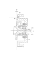
- the wheel includes a wheel 10 and an in-wheel motor 20.
- the wheel 10 includes a cylindrical rim portion 11 and a circular disc portion 12 provided at the outer end of the rim portion 11 in the vehicle width direction.
- a tire 13 is attached to the outer periphery of the rim portion 11.
- the in-wheel motor 20 is housed in the inner space of the wheel 10 surrounded by the rim portion 11 and the disk portion 12, and provides rotational power to the wheel 10.
- the in-wheel motor 20 is an outer rotor type motor including a rotor 30 and a stator 40 disposed radially inside the rotor 30.
- the rotor 30 includes a cylindrical magnet holder 31 and a magnet unit 32 provided on the inner peripheral surface of the magnet holder 31.
- the magnet holding portion 31 faces the inner circumferential surface of the rim portion 11 from the outer end to the inner end in the axial direction of the in-wheel motor 20 (vehicle width direction).
- the magnet unit 32 has a cylindrical shape concentric with the rotation center axis of the rotor 30 and includes a plurality of magnets fixed to the inner circumferential surface of the magnet holding part 31. That is, the in-wheel motor 20 of this embodiment is a surface magnet type synchronous machine (SPMSM). In the magnet unit 32, the magnets are arranged so that their polarities alternate along the circumferential direction of the rotor 30.
- SPMSM surface magnet type synchronous machine
- the magnet is, for example, a sintered neodymium magnet.
- the in-wheel motor 20 may be an embedded magnet type synchronous machine (IPMSM).
- the rotor 30 includes a disk-shaped flat plate portion 33 that is provided at the outer end in the vehicle width direction of the magnet holding portion 31 and connects the magnet holding portion 31 and the disk portion 12.
- the disk portion 12 is fixed to the flat plate portion 33 with bolts. As a result, the rotor 30 and the wheel 10 rotate together.
- the stator 40 includes a cylindrical stator winding 41 disposed at a position facing the magnet unit 32 in the radial direction, and a cylindrical stator base portion 42 provided inside the stator winding 41 in the radial direction. It is equipped with The stator winding 41 includes a coil side portion provided at a position facing the magnet unit 32 in the radial direction, and coil end portions provided at both ends of the coil side portion in the axial direction.
- the stator base portion 42 is fixed to the vehicle body via, for example, a knuckle, and holds the stator winding 41 and the like.
- the stator base portion 42 includes a cylindrical portion 43 fixed to the vehicle body. A portion of the cylindrical portion 43 that is adjacent to the stator winding 41 in the radial direction is a stator core 43a.
- the stator base portion 42 includes a fixing portion 44 extending radially inward from one axial end of the cylindrical portion 43.
- the rotor 30 is rotatably supported by the fixed part 44 and the bearing 50 with respect to the stator base part 42 .
- a radially outer end portion of the fixed portion 44 is an annular protrusion portion 45 that protrudes toward the flat plate portion 33 side.
- a portion of the protruding portion 45 that faces the flat plate portion 33 is a flat surface.
- the bearing 50 is a rolling bearing (for example, a radial ball bearing), and is arranged between an outer ring 51 corresponding to a "first bearing member”, an inner ring 52 corresponding to a “second bearing member”, and an outer ring 51 and an inner ring 52.
- a plurality of rolling elements 53 (for example, balls) are provided.
- the outer ring 51 is fixed to the fixed part 44 with bolts.
- the inner ring 52 includes a cylindrical portion 52a that faces the outer ring 51 in the radial direction, and a flange portion 52b that extends radially outward from one axial end of the cylindrical portion 52a.
- the flange portion 52b is fixed to the flat plate portion 33 and the disk portion 12 with bolts. Note that FIG. 1 shows a state in which the inner ring 52 and the outer ring 51 are coaxial.
- the vehicle is equipped with an inverter electrically connected to the stator winding 41 and a power storage unit electrically connected to the inverter.
- the power storage unit is provided in the vehicle body, and is, for example, a storage battery such as a lithium ion storage battery. Switching control of the upper and lower arm switches constituting the inverter is performed by a control device. This causes the rotor 30 to rotate and the wheels to rotate. Note that the inverter and the control device may be provided in the vehicle body, or may be built into the in-wheel motor 20.
- a disc-shaped race portion 80 corresponding to a "detection rotation section” and a detection unit 90 corresponding to a "displacement detection section” are provided in the inner space of the wheel 10.
- the race portion 80 and the detection unit 90 detect the rotation angle (specifically, electrical angle or mechanical angle) of the rotor 30 of the in-wheel motor 20, the rotation speed of the wheel, and the contact surface (ground) GL and the wheel (tire 13). ) is used to calculate the lateral force Fy that acts between the
- the calculated rotation angle (electrical angle) is used in the control device to control switching of the inverter, and the rotation speed and lateral force of the wheels are used in the control device to control the running of the vehicle.
- the race portion 80 has a disc shape and is made of a metal material (for example, iron or aluminum).
- a through hole is formed in the center of the race portion 80.
- a peripheral portion of the through hole of the race portion 80 is a bent portion 80a that is bent toward the disk portion 12.
- the bent portion 80a is fitted into a through hole formed in the center of the flat plate portion 33 of the rotor 30.
- the race portion 80 is spaced apart from the flat plate portion 33 of the rotor 30 and is fixed by bolts in a state in which it is in surface contact with the flange portion 52b of the inner ring 52. Thereby, the race portion 80 and the inner ring 52 are coaxial.
- the race portion 80, rotor 30, and wheel 10 rotate together.
- a radially outer end of the race portion 80 faces the protrusion 45 of the stator base portion 42 .
- shielding portions 81 which are metal portions, and notches 82, which penetrate the race portion 80 in the thickness direction, are alternately formed in the circumferential direction. ing.
- the shielding portion 81 and the notch 82 form an annular “detection target portion”.
- the circumferential length L1 of the shielding portion 81 and the circumferential length L2 of the notch 82 are equal.
- eight sets of shielding portions 81 and cutouts 82 are provided. Note that LCi shown in FIG. 2 indicates the central axis of the inner ring 52.
- the detection unit 90 is a so-called eddy current type inductive sensor.
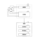
- the detection unit 90 includes a substrate 91, a coil section 92 provided on the substrate 91, and a circuit section 93, as shown in FIGS. 2, 4, and 5.
- FIG. 2 is a diagram showing the race portion 80 seen from the wheel 10 side.
- FIG. 4 is a diagram showing the substrate 91 viewed from the wheel 10 side.
- the substrate 91 is fixed to the flat surface of the protrusion 45 . Thereby, the substrate 91 extends in a direction perpendicular to the axial direction of the outer ring 51. In this embodiment, the substrate 91 is fixed to the flat surface of the upper end of the annular protrusion 45 .
- the circuit section 93 is electrically connected to the processing section 70.
- an insertion hole 46 is formed in the protrusion 45 , and the processing section 70 and the circuit section 93 are electrically connected via a wire inserted through the insertion hole 46 .
- the processing unit 70 may be provided in the vehicle body or may be built in the in-wheel motor 20.
- the coil section 92 includes an excitation coil 100, a first receiving coil 110, and a second receiving coil 120. Each coil 100, 110, 120 is a planar coil.
- the circuit section 93 is composed of an integrated circuit. As shown in FIG. 5, the circuit section 93 includes an excitation circuit 94 that supplies a high-frequency excitation voltage to the excitation coil 100, and a reception circuit 95. When an excitation voltage is supplied to the excitation coil 100, a voltage having the same or equivalent frequency as the excitation voltage is induced in the first reception coil 110 and the second reception coil 120.
- the receiving circuit 95 detects the voltage across each receiving coil 110, 120 as an output voltage signal.
- the board 91 is a multilayer board (specifically, a four-layer board), and the excitation coil 100 and each receiving coil 110, 120 that make up the coil section 92 are configured by wiring patterns on the multilayer board.
- ing. 7 to 10 show wiring patterns formed in each layer when the substrate 91 is viewed from the race portion 80 side.
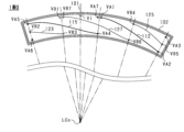
- FIG. 6(a) is a diagram in which the wiring patterns of the second to fourth layers are projected onto the wiring pattern of the first layer.
- the excitation coil 100 is formed in the first layer and the second layer adjacent to each other in the thickness direction of the substrate 91, as shown in FIGS. 7 and 8.
- the wiring patterns of each layer are electrically connected by a conductor filled in the excitation side via VI.
- a wiring pattern there is a first excitation end 101 electrically connected to the excitation circuit 94, and a wiring pattern that goes around clockwise multiple times (three times) from the first excitation end 101 to the excitation side via VI.
- a first excitation pattern 102 is formed.
- the second layer includes a second excitation end 103 electrically connected to the excitation circuit 94, and a second excitation end 103 that is formed by going around counterclockwise a plurality of times (three times) from the second excitation end 103 to the excitation side via VI.
- a second excitation pattern 104 is formed.
- the excitation coil 100 which is a six-turn planar coil, is formed on the substrate 91.
- the excitation coil 100 has an arcuate shape extending in the circumferential direction of the outer ring 51.
- the first receiving coil 110 is formed in the first to fourth layers, as shown in FIGS. 7 to 10.
- a first receiving end portion 111 electrically connected to the receiving circuit 95 is formed in the third layer.
- a first end of a first layer pattern 112 is connected to the first reception end portion 111 via a first A via VA1.
- the second end of the pattern 112 is connected to the first end of the second layer pattern 113 via the second A via VA2.
- the first end of the pattern 115 in the first layer is connected to the second end of the pattern 113 via the third A via VA3, the pattern 114, and the fourth A via VA4.
- the second end of the pattern 115 is connected to the first end of the second layer pattern 116 via the fifth A via VA5.
- the second receiving end portion 118 of the fourth layer is connected to the second end of the pattern 116 via the sixth A via VA6, the pattern 117, and the seventh A via VA7.
- the second receiving end 118 is connected to the receiving circuit 95.
- the receiving circuit 95 detects the potential difference between the first receiving end 111 and the second receiving end 118 as the first output voltage signal v1.
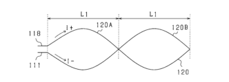
- the first receiving coil 110 is provided in a region surrounded by the excitation coil 100 in a plan view of the substrate 91, as shown in FIG. 6(a). Further, when the excitation voltage is supplied to the excitation coil 100, the first reception coil 110 applies a voltage of the first polarity between the first reception end 111 and the second reception end 118 of the first reception coil 110. It consists of a first part that generates a voltage and a second part that generates a voltage of a second polarity that is opposite to the first polarity. Specifically, as shown in FIG.
- the center portion of the first receiving coil 110 in the circumferential direction is the first portion 110A of one turn
- the first portion 110A of the first receiving coil 110 is Both ends of the first portion 110A are a second portion 110B having the same number of turns (one turn) as the first portion 110A.
- the pattern shape of the first and second portions 110A and 110B on one side with respect to the circumferential central axis Lt of the first receiving coil 110 and the pattern shape of the first and second portions 110A and 110B on the other side are changed. are symmetrical with respect to the central axis Lt.
- the second receiving coil 120 is formed in the first to fourth layers, as shown in FIGS. 7 to 10. As shown in FIG. 9, a third receiving end portion 121 electrically connected to the receiving circuit 95 is formed in the third layer.
- the first end of the second layer pattern 122 is connected to the third reception end portion 121 via the first B via VB1.
- the second end of the pattern 122 is connected to the first end of the first layer pattern 123 via the second B via VB2.
- the first end of the pattern 125 in the first layer is connected to the second end of the pattern 123 via the third A via VA3, the pattern 124, and the fourth B via VB4.
- a first end of a second layer pattern 126 is connected to the second end of the pattern 125 via a fifth B via VB5.
- the fourth reception end portion 128 of the fourth layer is connected to the second end of the pattern 126 via the sixth B via VB6, the pattern 127, and the seventh B via VB7.
- the fourth receiving end 128 is connected to the receiving circuit 95.
- the receiving circuit 95 detects the potential difference between the third receiving end 121 and the fourth receiving end 128 as a second output voltage signal v2.
- the second receiving coil 120 is provided in a region surrounded by the excitation coil 100 in a plan view of the substrate 91, as shown in FIG. 6(a).
- the circumferential length of the second receiving coil 120 is the same as the circumferential length of the first receiving coil 110.
- the radial length of the second receiving coil 120 is the same as the radial length of the first receiving coil 110.
- the positions of both ends of the second receiving coil 120 in the circumferential direction are the same as the positions of both ends of the first receiving coil 110 in the circumferential direction. Furthermore, in a plan view of the substrate 91, the position of the radially outer end of the second receiving coil 120 and the position of the radially outer end of the first receiving coil 110 are located on a concentric circle centered on the central axis LCo of the outer ring 51. exists in Further, in a plan view of the substrate 91, the position of the radially inner end of the second receiving coil 120 and the position of the radially inner end of the first receiving coil 110 exist on concentric circles centered on the central axis LCo. .
- the second receiving coil 120 is composed of a first portion 120A and a second portion 120B.
- one side with respect to the circumferential central axis Lt of the second receiving coil 120 is the first portion 120A, and the other side is the second portion 120B.
- the circumferential length from the central axis Lt to the circumferential end is the same as the circumferential length L1 of the shielding portion 81 and the notch 82.
- FIGS. 11 and 12 As shown in FIG. 11, when a high frequency excitation voltage vr(t) is supplied to the excitation coil, a high frequency current flows through the excitation coil. The current generates a magnetic flux ⁇ (t), which interlinks the receiving coil. A voltage ve(t) proportional to the time rate of change of the magnetic flux linkage is induced across the receiving coil.
- FIG. 12 shows a state in which a part of the receiving coil is covered by a shielding part that is a metal part.
- An eddy current flows through a portion of the shielding portion that faces the receiving coil due to interlinkage magnetic flux accompanying energization of the excitation coil.
- This eddy current generates magnetic flux in a direction that weakens the magnetic flux that generates the induced voltage in the receiving coil, and the amplitude of the induced voltage in the receiving coil becomes smaller.
- the amplitude of the potential difference between both ends of the receiving coil is proportional to the area of the receiving coil that is not covered by the shielding portion.
- FIGS. 11 and 12 are diagrams showing the second receiving coil 120 and the shielding part 81 shown in FIG. 6 etc. in a straight line in the circumferential direction.
- FIG. 14 is a diagram showing the relative positional relationship between the second receiving coil 120 and the shielding section 81 and the transition of the second output voltage signal v2 of the second receiving coil 120.
- the direction (I+) in which current flows from the second receiving end 118 to the first receiving end 111 is referred to as the positive direction;
- the direction in which the current flows (I-) will be referred to as the negative direction.
- the magnetic flux from the excitation coil 100 passes from the front side to the back side of the paper.
- the central half of the first portion 120A and the central half of the second portion 120B are covered by the shielding portion 81.
- a voltage that causes current to flow in the positive direction is induced in the first portion 120A
- a voltage that causes current to flow in the negative direction is induced in the second portion 120B.
- the induced voltage generated in the first portion 120A and the induced voltage generated in the second portion 120B cancel each other out, and the amplitude of the second output voltage signal v2 becomes zero.
- the second portion 120B of the first portion 120A and the second portion 120B is covered by the shielding portion 81.
- a voltage that causes current to flow in the positive direction is induced in the first portion 120A, and the induced voltage in the second portion 120B becomes zero.
- the amplitude of the second output voltage signal v2 becomes the maximum value on the first polarity (positive polarity) side. This maximum value increases as the lace portion 80 approaches the second receiving coil 120.
- the end half of the first portion 120A and the end half of the second portion 120B are covered by the shielding portion 81.
- a voltage that causes current to flow in the positive direction is induced in the first portion 120A
- a voltage that causes current to flow in the negative direction is induced in the second portion 120B.
- the induced voltage generated in the first portion 120A and the induced voltage generated in the second portion 120B cancel each other out, and the amplitude of the second output voltage signal v2 becomes zero.
- the first portion 120A of the first portion 120A and the second portion 120B is covered by the shielding portion 81.
- a voltage that causes current to flow in the negative direction is induced in the second portion 120B, and the induced voltage in the first portion 120A becomes zero.
- the amplitude of the second output voltage signal v2 becomes the maximum value on the second polarity (negative polarity) side, which is opposite to the first polarity. This maximum value increases as the lace portion 80 approaches the second receiving coil 120.
- shielding parts 81 and notches 82 are alternately formed at the radially outer end of the race part 80. Therefore, while the rotor 30 is rotating, the amplitude of the second output voltage signal v2 of the second receiving coil 120 changes periodically, and as shown by the broken line in FIGS. 14 and 15, the second output voltage signal v2 changes periodically.
- the envelope of v2 (hereinafter referred to as second envelope ENV2) has a sine wave shape. For example, by setting the circumferential spacing between the magnetic pole positions of the magnet unit 32 and the circumferential lengths of the shielding portion 81 and the notch 82 in a related manner, it is possible to associate the amplitude or the envelope with the electrical angle ⁇ e.
- the phase difference between the first output voltage signal v1 of the first reception coil 110 and the second output voltage signal v2 of the second reception coil 120 is 90 degrees. It is. Therefore, as shown by the dashed line in FIG. 15, the phase difference between the envelope of the first output voltage signal v1 (hereinafter referred to as first envelope ENV1) with respect to the second envelope ENV2 is also 90 degrees.
- the receiving circuit 95 transmits the deviation amount of the actual amplitude of the first envelope ENV1 from the amplitude of the first envelope ES1 in the reference state to the processing unit 70 as a first displacement signal.
- the reference state can be set arbitrarily.
- the reference state is, for example, a state in which the vehicle is stopped, and specifically, for example, a state in which the vehicle is stopped on a horizontal road surface.
- the receiving circuit 95 is configured so that the first displacement signal in the reference state is zero.
- the first displacement signal has positive polarity when the upper end of the race portion 80 approaches the first and second receiving coils 110 and 120 from the position in the reference state.
- the first displacement signal increases in the positive direction as the race portion 80 approaches the first and second receiving coils 110 and 120 from the position in the reference state.
- the first displacement signal has negative polarity when the upper end of the race portion 80 is separated from the first and second receiving coils 110 and 120 with respect to the position in the reference state.
- the first displacement signal increases in the negative direction as the upper end of the race portion 80 moves away from the first and second receiving coils 110 and 120 with respect to the position in the reference state.
- the first displacement signal is updated every time the maximum amplitude value on the positive polarity side and the maximum amplitude value on the negative polarity side of the first envelope ENV1 appear.
- the receiving circuit 95 outputs the deviation amount of the actual amplitude of the second envelope ENV2 from the amplitude of the second envelope ES2 in the reference state to the processing unit 70 as a second displacement signal.
- the receiving circuit 95 is configured so that the second displacement signal in the reference state is zero.
- the displacement calculating section 71 forming the processing section 70 calculates the displacement ⁇ L of the race section 80 in the axial direction based on the first displacement signal or the second displacement signal.
- the displacement calculation unit 71 calculates the displacement ⁇ L based on map information or formula information in which the displacement signal and the displacement ⁇ L are associated.
- the lateral force calculation unit 72 that constitutes the processing unit 70 calculates the lateral force based on the calculated displacement ⁇ L and map information or formula information in which the displacement ⁇ L and the lateral force Fy are related. Calculate Fy.
- the lateral force Fy is a positive value
- a lateral force acts on the wheels outward in the vehicle width direction
- a lateral force Fy acts on the wheels in a direction inward in the vehicle width direction.
- the lateral force calculation unit 72 calculates the lateral force based on the first displacement signal and map information or formula information in which the first displacement signal and the lateral force Fy are associated.
- the force Fy may also be calculated.
- the calculation of the lateral force Fy based on the displacement signal and the map information or mathematical information can be similarly applied to each of the following embodiments.
- the angle calculation unit 73 configuring the processing unit 70 calculates the rotation angle (for example, electrical angle ⁇ e) of the rotor 30 based on at least one of the first output voltage signal v1 and the second output voltage signal v2.
- the angle calculation unit 73 may calculate the electrical angle ⁇ e based on the first envelope ENV1 or the second envelope ENV2. This calculation method is based on the fact that the envelope is information indicating the transition of the amplitude of the output voltage signal and that the amplitude of the output voltage signal depends on the rotation angle.
- the angle calculation unit 73 may calculate the electrical angle ⁇ e by using synchronous detection and a low-pass filter with the first output voltage signal v1, the second output voltage signal v2, and the excitation voltage vr as input.
- This calculation method is a digital tracking method, and is described, for example, in paragraphs 0028 to 0030 of the specification of JP-A-2015-073407.
- a detection unit 90 is provided in the stator base portion 42 at a position radially away from the bearing 50 and facing the radial end of the race portion 80 in the axial direction.
- a portion of the race portion 80 that faces the detection unit 90 in the axial direction is a portion that is radially outwardly away from the bearing 50. Therefore, when a lateral force acts on the wheel, the axial displacement of the portion of the race portion 80 that faces the detection unit 90 in the axial direction can be increased. As a result, the accuracy in detecting the displacement ⁇ L can be improved, and in turn, the accuracy in calculating the lateral force Fy of the wheel forming the unsprung portion of the vehicle can be improved.
- the in-wheel motor 20 has an outer rotor type configuration, the radial end portion of the race portion 80 can be placed at a position largely separated from the bearing 50 in the radial direction. Thereby, the detection accuracy of displacement ⁇ L can be improved.
- the first receiving coil 110 and the second receiving coil 120 are provided closer to the wheel 10 in the axial direction than the coil end portions that constitute the stator winding 41. Thereby, it is possible to suppress the influence of noise and the like associated with energization of the stator winding 41 on the induced voltages of the first receiving coil 110 and the second receiving coil 120. As a result, the detection accuracy of displacement ⁇ L and rotation angle can be improved.
- the lace portion is not limited to the configuration shown in FIG. 1 etc., but may have the configurations shown in (A) and (B) below, for example.
- the race portion 83 is provided with shielding portions 85 and openings 84 passing through the race portion alternately in the circumferential direction.
- 83a in FIG. 17 corresponds to the bent portion 80a shown in FIGS. 1 and 2.
- the circumferential length of the opening 84 corresponds to the circumferential length of the notch 82 in FIG.
- the race portion 86 includes a convex portion 87 that protrudes from the flat surface of the race portion 86 in the axial direction of the inner ring 52, and a convex portion 87 that protrudes from the flat surface of the race portion 86 in the axial direction.
- concave portions 88 that are recessed in the axial direction of the inner ring 52 are provided alternately in the circumferential direction with respect to the convex portions 87 . Note that the circumferential length of the convex portion 87 corresponds to the circumferential length of the shielding portion 81 in FIG.
- the circumferential length of the recessed portion 88 corresponds to the circumferential length of the notch 82 in FIG.
- the detection unit 90 may be provided at a position facing the lower end of the race portion 80. Further, the detection unit 90 may be arranged on the disk portion 12 side with respect to the race portion 80.
- a first detection unit 90A and a second detection unit 90B are provided as detection units.
- the coil portion 92 (first and second receiving coils 110, 120) included in the first detection unit 90A is located in the protruding portion 45 of the stator base portion 42 and faces the upper end portion of the race portion 80 in the axial direction of the inner ring 52. It is located in a position where The coil section 92 (first and second receiving coils 110, 120) included in the second detection unit 90B is provided in the protrusion 45 at a position facing the lower end of the race section 80 in the axial direction of the inner ring 52.
- the substrates 91 of the first and second detection units 90A and 90B are arranged on the same side of the race portion 80 in the axial direction. Note that in FIG. 20, HL indicates a horizontal axis passing through the central axis LCi of the inner ring 52.
- the first and second output voltage signals v1A and v2A of the first and second receiving coils 110 and 120 of the first detection unit 90A are Each detection unit 90A, 90B is configured and arranged so that the phase difference between the first and second output voltage signals v1B, v2B of the two receiving coils 110, 120 is zero.
- the processing section 70 includes a differential amplifier circuit AP.
- the differential amplifier circuit AP amplifies the difference between the first output voltage signal v1A of the first detection unit 90A and the first output voltage signal v1B of the second detection unit 90B, and outputs it as a first amplified signal vt1. Further, the differential amplifier circuit AP amplifies the difference between the second output voltage signal v2A of the first detection unit 90A and the second output voltage signal v2B of the second detection unit 90B, and outputs it as a second amplified signal vt2. In the angle calculating section 73, the first and second amplified signals vt1 and vt2 are used to calculate the rotation angle instead of the first and second output voltage signals v1 and v2.
- the rotation angle may be calculated based on the first and second output voltage signals v1A, v2A of the first detection unit 90A, or the first and second output voltage signals v1B, v2B of the second detection unit 90B.
- the displacement calculation unit 71 calculates the amplitude of the envelope of the first amplified signal vt1 as a first displacement signal, and calculates the amplitude of the envelope of the second amplified signal vt2 as a second displacement signal. Since differential amplification is performed, it is possible to increase the amount of change in amplitude of the output voltage signal of each receiving coil 110, 120 with respect to the amount of change in axial displacement between coil portion 92 and race portion 80. In other words, the sensitivity of the inductive sensor can be increased. Thereby, the detection accuracy of displacement ⁇ L can be improved.
- FIG. 21(a) shows the transition of the envelope ENV1A of the first output voltage signal v1A in the first detection unit 90A
- FIG. 21(b) shows the envelope of the first output voltage signal v1B in the second detection unit 90B.
- the transition of ENV1B is shown.
- the phase difference between the first output voltage signal v1A of the first detection unit 90A and the first output voltage signal v1B of the second detection unit 90B is 0. Further, when no lateral force is acting on the wheel, the amplitude of the first output voltage signal v1A of the first detection unit 90A and the amplitude of the first output voltage signal v1B of the second detection unit 90B are the same. As a result, as shown by the broken line in the figure, the amplitudes of the envelopes ENV1A and ENV1B become the same, and the first amplified signal vt1 and the first displacement signal become zero.
- the inner ring 52 is moved relative to the outer ring 51 so that the upper end of the race portion 80 approaches the stator base portion 42 side and the lower end approaches the wheel 10 side. is tilted.
- the amplitude of the first output voltage signal v1A of the first detection unit 90A increases, and the amplitude of the first output voltage signal v1B of the second detection unit 90B decreases.
- the displacement calculating section 71 constituting the processing section 70 calculates the amplitudes of the envelopes of the first and second amplified signals vt1 and vt2 as the first and second displacement signals, and calculates the calculated first and second displacements. Based on either of the signals, the displacement ⁇ L of the race portion 80 in the axial direction is calculated.
- a coil part 92 of the first detection unit 90A is arranged at a position facing the upper end of the lace part 80
- a coil part 92 of the second detection unit 90B is arranged at a position facing the lower end of the lace part 80.
- the substrates 91 of the first and second detection units 90A and 90B are arranged on the same side in the axial direction with respect to the race portion 80.
- the upper end of the race portion 80 approaches the stator base portion 42 side, and the lower end approaches the wheel 10 side with respect to the outer ring 51.
- the inner ring 52 is tilted.
- the amplitude of the output voltage signal of each receiving coil 110, 120 of the first detection unit 90A increases, and the amplitude of the output voltage signal of each receiving coil 110, 120 of the second detection unit 90B decreases.
- a decrease in the amplitude of the output voltage signal on the second detection unit 90B side can be compensated for by an increase in the amplitude of the output voltage signal on the first detection unit 90A side.
- the amplitude of the output voltage signal of each receiving coil 110, 120 of the first detection unit 90A decreases, and the amplitude of the output voltage signal of each receiving coil 110, 120 of the second detection unit 90B increases.
- a decrease in the amplitude of the output voltage signal on the first detection unit 90A side can be compensated for by an increase in the amplitude of the output voltage signal on the second detection unit 90B side.
- the direction of the lateral force acting on the wheel is inward and outward in the vehicle width direction.
- the amplitude of the output voltage signal can be maintained as much as possible, regardless of which of the above conditions occurs. As a result, the detection accuracy of displacement ⁇ L can be maintained.
- the second detection unit 90B may be arranged on the opposite side of the race portion 80 from the first detection unit 90A.
- FIG. 22 is a diagram of the lace section 80 and each detection unit 90A, 90B viewed from above the lace section 80.
- the second detection unit 90B detects the first and second output voltage signals v1A and v2A of the first and second receiving coils 110 and 120 included in the first detection unit 90A.
- Each of the detection units 90A and 90B is configured and arranged so that the phase difference between the first and second output voltage signals v1B and v2B of the first and second receiving coils 110 and 120 of the detector is 0.
- the angle calculation section 73 calculates the rotation angle as in the second embodiment, and the displacement calculation section 71 calculates the first and second displacement signals as in the second embodiment.
- the first detection unit 90A and the second detection unit 90B may be provided at positions facing the lower end of the race portion 80.
- the fourth embodiment will be described below with reference to the drawings, focusing on the differences from the first embodiment.
- the coil section 92 first and second receiving coils 110, 120
- the coil section 92 straddles the horizontal axis HL passing through the rotation center of the race section 80 (the central axis LCi of the inner ring 52). It is set up as it was.
- the circumferential centers of the first and second receiving coils 110 and 120 are shifted upward with respect to the horizontal axis HL.
- This arrangement method will be described below using the second receiving coil 120 as an example.
- the induced voltage generated in the first portion 120A of the second receiving coil 120 and the induced voltage generated in the second portion 120B are different. will be in a state where they cancel each other out.
- the second output voltage signal v2 of the second receiving coil 120 becomes zero.
- the amplitude of the second output voltage signal v2 increases.
- the axial displacement of the race portion 80 near the horizontal axis HL is smaller than the radial end portion of the race portion 80 . Therefore, in a configuration in which the detection unit 90 is provided across the horizontal axis HL, the amplitude of the second output voltage signal v2 of the second receiving coil 120 tends to become small.
- the circumferential centers of the first and second receiving coils 110 and 120 are shifted upward with respect to the horizontal axis HL.
- the axial displacement between the second receiving coil 120 and the race portion 80 can be made as large as possible when the inner ring 52 is inclined with respect to the outer ring 51.
- the detection accuracy of displacement ⁇ L can be improved.
- a through hole 33a is formed in the radial center of the flat plate portion 33 constituting the rotor 30.
- An annular stepped portion 33b extending from a radially inner end toward the radially outer side is formed on the inner surface of the flat plate portion 33 in the vehicle width direction.
- the inner surface in the vehicle width direction of the stepped portion 33b is a flat surface.
- An annular positioning portion 33c that protrudes inward in the vehicle width direction is formed at the radially inner end of the stepped portion 33b.
- a through hole 80b is formed in the radially central portion of the race portion 80.
- the positioning portion 33c is fitted into the through hole 80b of the race portion 80 with the flat surface of the race portion 80 in contact with the flat surface of the stepped portion 33b. Thereby, the rotation center axis of the rotor 30 and the rotation center axis of the race portion 80 are made coaxial.
- a ring-shaped bearing-side step portion 52c that protrudes outward in the vehicle width direction is formed at the radially inner end of the flange portion 52b of the inner ring 52.
- a radially inner portion of the flat plate portion 33 than the positioning portion 33c is formed with an annular recess 33d that is recessed outward in the vehicle width direction.
- a first through hole that penetrates in the axial direction is formed in the flat plate portion 33, the race portion 80, and the flange portion 52b.
- a plurality of first through holes are formed side by side in the circumferential direction (for example, lined up at equal intervals in the circumferential direction).
- a bolt 200 is inserted into each first through hole. The bolt 200 is inserted into the first through hole with the head of the bolt 200 facing outward in the vehicle width direction and the shaft portion of the bolt 200 facing inward in the vehicle width direction. In this inserted state, the male thread at the tip of the shaft portion is screwed into the female thread of the nut 201. As a result, the overlapping flat plate portion 33, race portion 80, and flange portion 52b are sandwiched between the head of the bolt 200 and the nut 201. As a result, the rotor 30, race portion 80, and bearing 50 are integrated.
- a second through hole that penetrates in the axial direction is formed in the flat plate portion 33, the race portion 80, the flange portion 52b, and the disk portion 12.
- a plurality of second through-holes are formed at positions offset from the formation positions of the first through-holes and lined up in the circumferential direction (for example, lined up at equal intervals in the circumferential direction).
- a bolt 210 is inserted into each second through hole. The bolt 210 is inserted into the second through hole with the head of the bolt 210 facing inward in the vehicle width direction and the shaft portion of the bolt 210 facing outside in the vehicle width direction. In this inserted state, the male thread of the bolt 210 is screwed into the female thread of the nut 211.
- the positioning portion 33c is fitted into the through hole 80b of the race portion 80 with the flat surface of the race portion 80 in contact with the flat surface of the stepped portion 33b. Thereafter, the bearing side step part 52c is fitted into the recess 33d while the race part 80 is sandwiched between the step part 33b and the flange part 52b.
- the bolt 200 is inserted into each first through hole with the head of the bolt 200 facing the outside of the rotor 30. Then, the female thread of the nut 201 is screwed into the male thread of the bolt 200. As a result, the overlapping flat plate portion 33, race portion 80, and flange portion 52b are sandwiched between the head of the bolt 200 and the nut 201.
- the flat surface of the race portion 80 is brought into contact with the flat surface of the stepped portion 33b, warping of the race portion 80 when the nut 201 is screwed onto the bolt 200 can be suppressed.
- the positioning portion 33c is fitted into the through hole 80b of the race portion 80 with the flat surface of the race portion 80 in contact with the flat surface of the stepped portion 33b. In this state, the race portion 80 and the stepped portion 33b are fixed by the bolts 220.
- a first through hole that penetrates in the axial direction is formed in the flat plate portion 33 and the flange portion 52b.
- a plurality of first through holes are formed side by side in the circumferential direction (for example, lined up at equal intervals in the circumferential direction).
- a bolt 230 is inserted into each first through hole.
- the bolt 230 is inserted into the first through hole with the head of the bolt 230 facing inward in the vehicle width direction and the shaft portion of the bolt 230 facing outside in the vehicle width direction.
- the male thread of the bolt 230 is screwed into the female thread of the nut 231.
- the overlapping flat plate portion 33 and flange portion 52b are sandwiched between the head of the bolt 230 and the nut 231.
- the rotor 30, race portion 80, and bearing 50 are integrated.
- a second through hole that penetrates in the axial direction is formed in the flat plate portion 33, the flange portion 52b, and the disk portion 12.
- a plurality of second through-holes are formed in a row in the circumferential direction (for example, in a row at equal intervals in the circumferential direction) at positions shifted from the formation positions of the first through-holes in the radial direction.
- a bolt 240 is inserted into each second through hole. The bolt 240 is inserted into the second through hole with the head of the bolt 240 facing inward in the vehicle width direction and the shaft portion of the bolt 240 facing outside in the vehicle width direction. In this inserted state, the male thread of the bolt 240 is screwed into the female thread of the nut 241. As a result, the overlapping flat plate portion 33, flange portion 52b, and disk portion 12 are sandwiched between the head of the bolt 240 and the nut 241. As a result, the rotor 30 and the wheel 10 are integrated.
- the circumferential centers of the first and second receiving coils 110 and 120 may be shifted downward with respect to the horizontal axis HL.
- a non-metallic part such as synthetic resin may be provided in the notch 82 in FIG. 2 or the opening 84 in FIG. 17.
- a configuration in which metal portions and non-metal portions are alternately provided in the circumferential direction can be realized, and the rotation angle can be detected in the same manner as in the first embodiment.
- the in-wheel motor 20 shown in FIG. 1 does not need to include the race portion 80.
- shielding portions and openings may be formed alternately in the circumferential direction in a portion of the flat plate portion 33 of the in-wheel motor 20 that faces the coil portion 92 in the axial direction, or recessed portions and convex portions may be formed in the circumferential direction. They may be formed alternately in the directions.
- the flat plate part 33 corresponds to the "detection rotating part".
- the receiving coil formed on the substrate 91 may be either the first receiving coil 110 or the second receiving coil 120.
- the sensor that detects displacement is not limited to an eddy current sensor, but may be a sensor that detects displacement using laser light, for example.
- the bearing is not limited to one in which the outer ring 51 is fixed to the stator base part 42 and the inner ring 52 is fixed to the wheel 10, but it is also possible to use a bearing in which the outer ring is fixed to the wheel 10 and the inner ring is fixed to the stator base part 42. It may be something that you have. In this case, the inner ring corresponds to the "first bearing member” and the outer ring corresponds to the "second bearing member.”
- the motor is not limited to one that is housed in a wheel, but may be an on-board motor provided in the vehicle body, for example. Further, the motor is not limited to an outer rotor type, but may be an inner rotor type.
- control unit and the method described in the present disclosure are implemented by a dedicated computer provided by configuring a processor and memory programmed to perform one or more functions embodied by a computer program. May be realized.
- the controller and techniques described in this disclosure may be implemented by a dedicated computer provided by a processor configured with one or more dedicated hardware logic circuits.
- the control unit and the method described in the present disclosure may be implemented using a combination of a processor and memory programmed to perform one or more functions and a processor configured by one or more hardware logic circuits. It may be implemented by one or more dedicated computers configured.
- the computer program may also be stored as instructions executed by a computer on a computer-readable non-transitory tangible storage medium.
- a bearing (50); Of the outer ring member and the inner ring member, one of the first bearing members (52) is fixed to the wheel, and the other, the second bearing member (51), is fixed to the base part, a disc-shaped detection rotating part (80, 83, 86) that is provided to rotate integrally with the first bearing member and extends radially outward of the bearing with respect to the first bearing member;
- the base portion is provided at a position away from the bearing in the radial direction and facing the detection rotation unit in the axial direction of the bearing, in a non-contact state with the detection rotation unit, a displacement detection section (90, 90A, 90B) that outputs a signal according to the displacement of the detection rotating section in the axial direction;
- a vehicle detection device comprising: [Configuration 2] An annular detection target portion (81, 82, 84, 85, 87, 88) extending in the circumferential direction of the bearing is formed at a position away from the bearing in the radial direction of the detection rotating portion.
- the displacement detection section includes: a planar receiving coil (110, 120) fixed to the base part, provided at a position facing the detection target part in the axial direction, and extending in a direction intersecting the axial direction; an excitation coil (100) to which an alternating current excitation voltage is supplied; has A voltage is induced in the receiving coil when the excitation voltage is supplied to the excitation coil,
- the vehicle detection device according to configuration 1, further comprising a processing unit (70) that calculates the displacement of the detection rotating unit in the axial direction based on the output voltage signal of the receiving coil.
- the detection target part is A configuration in which metal portions (81) and portions (82) penetrated in the axial direction are provided alternately in the circumferential direction; A configuration in which recessed portions (88) recessed in the axial direction and convex portions (87) protruding in the axial direction with respect to the recessed portions are provided alternately in the circumferential direction, or a metal portion and a non-metallic portion are provided in the It has a configuration in which they are arranged alternately in the circumferential direction,
- the vehicle detection device according to configuration 2, wherein the processing section further calculates the rotation angle of the detection rotating section based on the output voltage signal of the receiving coil.
- the receiving coil is a first receiving coil (110) in which a voltage is induced when the excitation voltage is supplied to the excitation coil; a second receiving coil (120) in which a voltage that is out of phase with the induced voltage of the first receiving coil is induced when the excitation voltage is supplied to the exciting coil;
- the vehicle detection device according to configuration 3, wherein the processing unit calculates the rotation angle based on output voltage signals of the first receiving coil and the second receiving coil.
- the displacement detection unit includes a first displacement detection unit (90A) and a second displacement detection unit (90B),
- the receiving coil included in the first displacement detection section is provided at a position facing the upper end of the detection rotation section in the axial direction
- the vehicle detection according to any one of configurations 2 to 4, wherein the receiving coil included in the second displacement detection section is provided at a position facing the lower end of the detection rotation section in the axial direction.
- the displacement detection unit includes a first displacement detection unit (90A) and a second displacement detection unit (90B),
- the receiving coil included in the first displacement detection section is provided at a position facing the upper end or the lower end of the detection rotating section in the axial direction
- the receiving coil included in the second displacement detecting section is provided on a side opposite to the receiving coil provided in the first displacement detecting section across the detection rotating section in the axial direction, Configuration 2 to 4.
- the vehicle detection device according to any one of 4.
- the first displacement detection unit so that the phase of the output voltage signal of the reception coil included in the first displacement detection unit is the same as the phase of the output voltage signal of the reception coil included in the second displacement detection unit; and the second displacement detection section is configured, an amplification unit (AP) that amplifies and outputs a difference between an output voltage signal of the receiving coil included in the first displacement detection unit and an output voltage signal of the receiving coil included in the second displacement detection unit;
- AP amplification unit
- the receiving coil is a first portion (110A, 120A) that generates a voltage of a first polarity across the receiving coil when the excitation voltage is supplied to the excitation coil; a second portion (110B, 120B) that generates a voltage of a second polarity opposite to the first polarity across the receiving coil when the excitation voltage is supplied to the excitation coil; has The receiving coil is In a plan view of the receiving coil, the first portion (120A) is provided on one side with respect to the center of the receiving coil in the circumferential direction, and the second portion (120B) is provided on the other side, and , the first portion and the second portion are arranged in the circumferential direction, or the first portion (110A ) and the second part (110B) and the first part and the second part on the other side are configured symmetrically with respect to the center, The receiving coil is provided so as to straddle a horizontal axis passing through the rotation center axis of the detection rotating part, 5.
Landscapes
- Engineering & Computer Science (AREA)
- General Engineering & Computer Science (AREA)
- Mechanical Engineering (AREA)
- Physics & Mathematics (AREA)
- General Physics & Mathematics (AREA)
- Transmission And Conversion Of Sensor Element Output (AREA)
- Force Measurement Appropriate To Specific Purposes (AREA)
- Rolling Contact Bearings (AREA)
Abstract
Description
外輪部材、内輪部材、及び前記外輪部材と前記内輪部材との間に設けられる転動体を有し、前記車両の車輪を前記ベース部に対して回転可能に支持する軸受と、を備え、
前記外輪部材及び前記内輪部材のうち、一方である第1軸受部材が前記車輪に対して固定され、他方である第2軸受部材が前記ベース部に対して固定され、
前記第1軸受部材と一体回転するように設けられ、前記第1軸受部材に対して前記軸受の径方向外側に延びる円盤状の検出用回転部と、
前記ベース部のうち、前記径方向において前記軸受から離れた位置であって、前記軸受の軸方向において前記検出用回転部と対向する位置に前記検出用回転部と非接触の状態で設けられ、前記検出用回転部の前記軸方向の変位に応じた信号を出力する変位検出部と、を備える。
以下、本開示に係る車両用検出装置を具体化した第1実施形態について、図面を参照しつつ説明する。本実施形態の検出装置は、インホイールモータを備える車輪(駆動輪)に作用する横力を算出可能に構成されている。車両は、例えば、2つの前輪及び2つの後輪を有する乗用の4輪車両である。ただし、車両としては、これに限らず、2輪車両等、4輪以外の車両であってもよい。また、車両の用途としては、乗用に限らない。
・レース部は、図1等に示した構成に限らず、例えば、以下(A),(B)の構成であってもよい。
以下、第2実施形態について、第1実施形態との相違点を中心に図面を参照しつつ説明する。本実施形態では、図20に示すように、検出ユニットとして、第1検出ユニット90A及び第2検出ユニット90Bが設けられている。第1検出ユニット90Aが備えるコイル部92(第1,第2受信コイル110,120)は、固定子ベース部42の突出部45のうち、内輪52の軸方向においてレース部80の上端部と対向する位置に設けられている。第2検出ユニット90Bが備えるコイル部92(第1,第2受信コイル110,120)は、突出部45のうち、内輪52の軸方向においてレース部80の下端部と対向する位置に設けられている。第1,第2検出ユニット90A,90Bの基板91は、レース部80に対して軸方向で同じ側に配置されている。なお、図20において、HLは、内輪52の中心軸線LCiを通る水平軸線を示す。
第2検出ユニット90Bが、レース部80に対して第1検出ユニット90Aとは反対側に配置されていてもよい。
以下、第3実施形態について、第2実施形態との相違点を中心に図面を参照しつつ説明する。本実施形態では、図22に示すように、第2検出ユニット90Bが備える基板91及びコイル部92は、外輪51の中心軸線LCoの方向において、レース部80を挟んで第1検出ユニット90Aが備える基板91及びコイル部92側とは反対側に設けられている。つまり、第1検出ユニット90A及び第2検出ユニット90Bがレース部80の上端部と対向する位置に設けられている。図22は、レース部80及び各検出ユニット90A,90Bをレース部80の上方から見た図である。本実施形態においても、回転子30の回転中において、第1検出ユニット90Aが備える第1,第2受信コイル110,120の第1,第2出力電圧信号v1A,v2Aに対する、第2検出ユニット90Bが備える第1,第2受信コイル110,120の第1,第2出力電圧信号v1B,v2Bの位相差が0となるように、各検出ユニット90A,90Bが構成及び配置されている。角度算出部73は、第2実施形態と同様に回転角を算出し、変位算出部71は、第2実施形態と同様に第1,第2変位信号を算出する。
第1検出ユニット90A及び第2検出ユニット90Bがレース部80の下端部と対向する位置に設けられていてもよい。
以下、第4実施形態について、第1実施形態との相違点を中心に図面を参照しつつ説明する。本実施形態では、図23に示すように、コイル部92(第1,第2受信コイル110,120)が、レース部80の回転中心(内輪52の中心軸線LCi)を通る水平軸線HLを跨いた状態で設けられている。これにより、第1,第2受信コイル110,120の周方向の中央が水平軸線HLに対して上方向にずれた位置になっている。以下、この配置方法について、第2受信コイル120を例にして説明する。
以下、第5実施形態について、第1実施形態との相違点を中心に図面を参照しつつ説明する。本実施形態では、図24に示すように、回転子30、レース部80及び軸受50の同軸度を小さくできる構成が採用されている。なお、図24において、先の図1等に示した構成と同一の構成又は対応する構成については、便宜上、同一の符号を付している。また、本実施形態のレース部80には屈曲部80aが形成されていない。
以下、第6実施形態について、第5実施形態との相違点を中心に図面を参照しつつ説明する。本実施形態では、図25に示すように、レース部80が、内輪52ではなく、回転子30に固定されている。なお、図25において、先の図24等に示した構成と同一の構成又は対応する構成については、便宜上、同一の符号を付している。
なお、上記各実施形態は、以下のように変更して実施してもよい。
[構成1]
車両の車体に対して固定されるベース部(42)と、
外輪部材(51)、内輪部材(52)、及び前記外輪部材と前記内輪部材との間に設けられる転動体(53)を有し、前記車両の車輪を前記ベース部に対して回転可能に支持する軸受(50)と、を備え、
前記外輪部材及び前記内輪部材のうち、一方である第1軸受部材(52)が前記車輪に対して固定され、他方である第2軸受部材(51)が前記ベース部に対して固定され、
前記第1軸受部材と一体回転するように設けられ、前記第1軸受部材に対して前記軸受の径方向外側に延びる円盤状の検出用回転部(80,83,86)と、
前記ベース部のうち、前記径方向において前記軸受から離れた位置であって、前記軸受の軸方向において前記検出用回転部と対向する位置に前記検出用回転部と非接触の状態で設けられ、前記検出用回転部の前記軸方向の変位に応じた信号を出力する変位検出部(90,90A,90B)と、
を備える、車両用検出装置。
[構成2]
前記検出用回転部のうち前記径方向において前記軸受から離れた位置には、前記軸受の周方向に延びる円環状の検出対象部(81,82,84,85,87,88)が形成されており、
前記変位検出部は、
前記ベース部に対して固定されるとともに前記軸方向において前記検出対象部と対向する位置に設けられ、前記軸方向と交差する方向に延びる平面状の受信コイル(110,120)と、
交流の励磁電圧が供給される励磁コイル(100)と、
を有し、
前記受信コイルは、前記励磁コイルに前記励磁電圧が供給されている場合に電圧が誘起され、
前記受信コイルの出力電圧信号に基づいて、前記検出用回転部の前記軸方向の変位を算出する処理部(70)を備える、構成1に記載の車両用検出装置。
[構成3]
前記検出対象部は、
金属部分(81)と、前記軸方向において貫かれた部分(82)とが前記周方向において交互に設けられた構成、
前記軸方向に凹む凹部(88)と、前記凹部に対して前記軸方向に突出する凸部(87)とが前記周方向において交互に設けられた構成、又は
金属部分と非金属部分とが前記周方向において交互に設けられた構成
になっており、
前記処理部は、前記受信コイルの出力電圧信号に基づいて、前記検出用回転部の回転角を更に算出する、構成2に記載の車両用検出装置。
[構成4]
前記受信コイルは、
前記励磁コイルに前記励磁電圧が供給されている場合に電圧が誘起される第1受信コイル(110)と、
前記励磁コイルに前記励磁電圧が供給されている場合に、前記第1受信コイルの誘起電圧に対して位相がずれた電圧が誘起される第2受信コイル(120)と、を含み、
前記処理部は、前記第1受信コイル及び前記第2受信コイルの出力電圧信号に基づいて、前記回転角を算出する、構成3に記載の車両用検出装置。
[構成5]
前記変位検出部として、第1変位検出部(90A)及び第2変位検出部(90B)を備え、
前記第1変位検出部が備える前記受信コイルは、前記軸方向において前記検出用回転部の上端部と対向する位置に設けられ、
前記第2変位検出部が備える前記受信コイルは、前記軸方向において前記検出用回転部の下端部と対向する位置に設けられている、構成2~4のいずれか1つに記載の車両用検出装置。
[構成6]
前記変位検出部として、第1変位検出部(90A)及び第2変位検出部(90B)を備え、
前記第1変位検出部が備える前記受信コイルは、前記軸方向において前記検出用回転部の上端部又は下端部と対向する位置に設けられ、
前記第2変位検出部が備える前記受信コイルは、前記軸方向において前記検出用回転部を挟んで前記第1変位検出部が備える前記受信コイル側とは反対側に設けられている、構成2~4のいずれか1つに記載の車両用検出装置。
[構成7]
前記第1変位検出部が備える前記受信コイルの出力電圧信号の位相と、前記第2変位検出部が備える前記受信コイルの出力電圧信号の位相とが同じになるように、前記第1変位検出部及び前記第2変位検出部が構成され、
前記第1変位検出部が備える前記受信コイルの出力電圧信号と、前記第2変位検出部が備える前記受信コイルの出力電圧信号との差を増幅して出力する増幅部(AP)を備え、
前記処理部は、前記増幅部の出力電圧信号に基づいて前記変位を算出する、構成5又は6に記載の車両用検出装置。
[構成8]
前記受信コイルは、
前記励磁コイルに前記励磁電圧が供給されている場合に前記受信コイルの両端に第1極性の電圧を発生させる第1部分(110A,120A)と、
前記励磁コイルに前記励磁電圧が供給されている場合に前記受信コイルの両端に前記第1極性とは逆極性の第2極性の電圧を発生する第2部分(110B,120B)と、
を有し、
前記受信コイルは、
前記受信コイルの平面視において、前記受信コイルの前記周方向の中央に対して一方側に前記第1部分(120A)が設けられるとともに他方側に前記第2部分(120B)が設けられて、かつ、前記第1部分と前記第2部分とが前記周方向に並んだ構成、又は
前記受信コイルの平面視において、前記受信コイルの前記周方向の中央に対して一方側の前記第1部分(110A)及び前記第2部分(110B)と他方側の前記第1部分及び前記第2部分とが、前記中央に対して対称の構成
になっており、
前記受信コイルは、前記検出用回転部の回転中心軸線を通る水平軸線を跨いた状態で設けられ、
前記受信コイルの前記周方向の中央が前記水平軸線に対して上下方向にずれた位置になっている、構成2~4のいずれか1つに記載の車両用検出装置。
[構成9]
前記処理部は、算出した前記変位に基づいて、前記車輪に作用する横力を算出する、構成2~8のいずれか1つに記載の車両用検出装置。
Claims (9)
- 車両の車体に対して固定されるベース部(42)と、
外輪部材(51)、内輪部材(52)、及び前記外輪部材と前記内輪部材との間に設けられる転動体(53)を有し、前記車両の車輪を前記ベース部に対して回転可能に支持する軸受(50)と、を備え、
前記外輪部材及び前記内輪部材のうち、一方である第1軸受部材(52)が前記車輪に対して固定され、他方である第2軸受部材(51)が前記ベース部に対して固定され、
前記第1軸受部材と一体回転するように設けられ、前記第1軸受部材に対して前記軸受の径方向外側に延びる円盤状の検出用回転部(80,83,86)と、
前記ベース部のうち、前記径方向において前記軸受から離れた位置であって、前記軸受の軸方向において前記検出用回転部と対向する位置に前記検出用回転部と非接触の状態で設けられ、前記検出用回転部の前記軸方向の変位に応じた信号を出力する変位検出部(90,90A,90B)と、
を備える、車両用検出装置。 - 前記検出用回転部のうち前記径方向において前記軸受から離れた位置には、前記軸受の周方向に延びる円環状の検出対象部(81,82,84,85,87,88)が形成されており、
前記変位検出部は、
前記ベース部に対して固定されるとともに前記軸方向において前記検出対象部と対向する位置に設けられ、前記軸方向と交差する方向に延びる平面状の受信コイル(110,120)と、
交流の励磁電圧が供給される励磁コイル(100)と、
を有し、
前記受信コイルは、前記励磁コイルに前記励磁電圧が供給されている場合に電圧が誘起され、
前記受信コイルの出力電圧信号に基づいて、前記検出用回転部の前記軸方向の変位を算出する処理部(70)を備える、請求項1に記載の車両用検出装置。 - 前記検出対象部は、
金属部分(81)と、前記軸方向において貫かれた部分(82)とが前記周方向において交互に設けられた構成、
前記軸方向に凹む凹部(88)と、前記凹部に対して前記軸方向に突出する凸部(87)とが前記周方向において交互に設けられた構成、又は
金属部分と非金属部分とが前記周方向において交互に設けられた構成
になっており、
前記処理部は、前記受信コイルの出力電圧信号に基づいて、前記検出用回転部の回転角を更に算出する、請求項2に記載の車両用検出装置。 - 前記受信コイルは、
前記励磁コイルに前記励磁電圧が供給されている場合に電圧が誘起される第1受信コイル(110)と、
前記励磁コイルに前記励磁電圧が供給されている場合に、前記第1受信コイルの誘起電圧に対して位相がずれた電圧が誘起される第2受信コイル(120)と、を含み、
前記処理部は、前記第1受信コイル及び前記第2受信コイルの出力電圧信号に基づいて、前記回転角を算出する、請求項3に記載の車両用検出装置。 - 前記変位検出部として、第1変位検出部(90A)及び第2変位検出部(90B)を備え、
前記第1変位検出部が備える前記受信コイルは、前記軸方向において前記検出用回転部の上端部と対向する位置に設けられ、
前記第2変位検出部が備える前記受信コイルは、前記軸方向において前記検出用回転部の下端部と対向する位置に設けられている、請求項2~4のいずれか1項に記載の車両用検出装置。 - 前記変位検出部として、第1変位検出部(90A)及び第2変位検出部(90B)を備え、
前記第1変位検出部が備える前記受信コイルは、前記軸方向において前記検出用回転部の上端部又は下端部と対向する位置に設けられ、
前記第2変位検出部が備える前記受信コイルは、前記軸方向において前記検出用回転部を挟んで前記第1変位検出部が備える前記受信コイル側とは反対側に設けられている、請求項2~4のいずれか1項に記載の車両用検出装置。 - 前記第1変位検出部が備える前記受信コイルの出力電圧信号の位相と、前記第2変位検出部が備える前記受信コイルの出力電圧信号の位相とが同じになるように、前記第1変位検出部及び前記第2変位検出部が構成され、
前記第1変位検出部が備える前記受信コイルの出力電圧信号と、前記第2変位検出部が備える前記受信コイルの出力電圧信号との差を増幅して出力する増幅部(AP)を備え、
前記処理部は、前記増幅部の出力電圧信号に基づいて前記変位を算出する、請求項5に記載の車両用検出装置。 - 前記受信コイルは、
前記励磁コイルに前記励磁電圧が供給されている場合に前記受信コイルの両端に第1極性の電圧を発生させる第1部分(110A,120A)と、
前記励磁コイルに前記励磁電圧が供給されている場合に前記受信コイルの両端に前記第1極性とは逆極性の第2極性の電圧を発生する第2部分(110B,120B)と、
を有し、
前記受信コイルは、
前記受信コイルの平面視において、前記受信コイルの前記周方向の中央に対して一方側に前記第1部分(120A)が設けられるとともに他方側に前記第2部分(120B)が設けられて、かつ、前記第1部分と前記第2部分とが前記周方向に並んだ構成、又は
前記受信コイルの平面視において、前記受信コイルの前記周方向の中央に対して一方側の前記第1部分(110A)及び前記第2部分(110B)と他方側の前記第1部分及び前記第2部分とが、前記中央に対して対称の構成
になっており、
前記受信コイルは、前記検出用回転部の回転中心軸線を通る水平軸線を跨いた状態で設けられ、
前記受信コイルの前記周方向の中央が前記水平軸線に対して上下方向にずれた位置になっている、請求項2~4のいずれか1項に記載の車両用検出装置。 - 前記処理部は、算出した前記変位に基づいて、前記車輪に作用する横力を算出する、請求項2~4のいずれか1項に記載の車両用検出装置。
Priority Applications (3)
| Application Number | Priority Date | Filing Date | Title |
|---|---|---|---|
| EP23766825.6A EP4492027A1 (en) | 2022-03-07 | 2023-03-07 | Vehicular detection device |
| CN202380025760.5A CN118829859A (zh) | 2022-03-07 | 2023-03-07 | 车辆用检测装置 |
| US18/828,215 US20240426345A1 (en) | 2022-03-07 | 2024-09-09 | Detection device for vehicles |
Applications Claiming Priority (2)
| Application Number | Priority Date | Filing Date | Title |
|---|---|---|---|
| JP2022034711A JP2023130184A (ja) | 2022-03-07 | 2022-03-07 | 車両用検出装置 |
| JP2022-034711 | 2022-03-07 |
Related Child Applications (1)
| Application Number | Title | Priority Date | Filing Date |
|---|---|---|---|
| US18/828,215 Continuation US20240426345A1 (en) | 2022-03-07 | 2024-09-09 | Detection device for vehicles |
Publications (1)
| Publication Number | Publication Date |
|---|---|
| WO2023171649A1 true WO2023171649A1 (ja) | 2023-09-14 |
Family
ID=87935063
Family Applications (1)
| Application Number | Title | Priority Date | Filing Date |
|---|---|---|---|
| PCT/JP2023/008503 WO2023171649A1 (ja) | 2022-03-07 | 2023-03-07 | 車両用検出装置 |
Country Status (5)
| Country | Link |
|---|---|
| US (1) | US20240426345A1 (ja) |
| EP (1) | EP4492027A1 (ja) |
| JP (1) | JP2023130184A (ja) |
| CN (1) | CN118829859A (ja) |
| WO (1) | WO2023171649A1 (ja) |
Citations (6)
| Publication number | Priority date | Publication date | Assignee | Title |
|---|---|---|---|---|
| JP2006003268A (ja) * | 2004-06-18 | 2006-01-05 | Ntn Corp | 荷重センサ内蔵車輪用軸受装置 |
| JP2006258572A (ja) * | 2005-03-16 | 2006-09-28 | Jtekt Corp | 変位センサ付きハブユニット |
| JP2006275251A (ja) * | 2005-03-30 | 2006-10-12 | Jtekt Corp | センサ付き転がり軸受装置 |
| US20080144985A1 (en) * | 2006-12-15 | 2008-06-19 | The Timken Company | Wheel End With Monitoring Capabilities |
| JP2015073407A (ja) | 2013-10-04 | 2015-04-16 | 株式会社デンソー | 絶縁電源装置 |
| JP2022034711A (ja) | 2020-08-19 | 2022-03-04 | 利浩 林 | シートクッション、又はシート |
-
2022
- 2022-03-07 JP JP2022034711A patent/JP2023130184A/ja active Pending
-
2023
- 2023-03-07 WO PCT/JP2023/008503 patent/WO2023171649A1/ja active Application Filing
- 2023-03-07 CN CN202380025760.5A patent/CN118829859A/zh active Pending
- 2023-03-07 EP EP23766825.6A patent/EP4492027A1/en active Pending
-
2024
- 2024-09-09 US US18/828,215 patent/US20240426345A1/en active Pending
Patent Citations (6)
| Publication number | Priority date | Publication date | Assignee | Title |
|---|---|---|---|---|
| JP2006003268A (ja) * | 2004-06-18 | 2006-01-05 | Ntn Corp | 荷重センサ内蔵車輪用軸受装置 |
| JP2006258572A (ja) * | 2005-03-16 | 2006-09-28 | Jtekt Corp | 変位センサ付きハブユニット |
| JP2006275251A (ja) * | 2005-03-30 | 2006-10-12 | Jtekt Corp | センサ付き転がり軸受装置 |
| US20080144985A1 (en) * | 2006-12-15 | 2008-06-19 | The Timken Company | Wheel End With Monitoring Capabilities |
| JP2015073407A (ja) | 2013-10-04 | 2015-04-16 | 株式会社デンソー | 絶縁電源装置 |
| JP2022034711A (ja) | 2020-08-19 | 2022-03-04 | 利浩 林 | シートクッション、又はシート |
Also Published As
| Publication number | Publication date |
|---|---|
| EP4492027A1 (en) | 2025-01-15 |
| JP2023130184A (ja) | 2023-09-20 |
| US20240426345A1 (en) | 2024-12-26 |
| CN118829859A (zh) | 2024-10-22 |
Similar Documents
| Publication | Publication Date | Title |
|---|---|---|
| JP4844010B2 (ja) | 荷重測定装置付転がり軸受ユニット | |
| US5663641A (en) | Rotational speed detection unit | |
| JP5041401B2 (ja) | 回転センサ | |
| JP5128120B2 (ja) | 回転センサ | |
| JP2004003918A (ja) | 荷重測定装置付車輪支持用転がり軸受ユニット | |
| JPH11118818A (ja) | 車両における回転数検出用センサの取付構造及び歯車 | |
| JP2022541383A (ja) | 本体の軸方向位置及び回転位置の決定 | |
| JP3635707B2 (ja) | 回転速度検出装置付転がり軸受ユニット | |
| JP5099245B2 (ja) | 荷重測定装置付転がり軸受ユニット | |
| JP5202343B2 (ja) | 回転角検出器 | |
| WO2023171649A1 (ja) | 車両用検出装置 | |
| JP2012112897A (ja) | 回転角度位置検出装置及びこれを使用したセンサ付き転がり軸受 | |
| US20240159510A1 (en) | Rotational angle measurement apparatus | |
| JP5137755B2 (ja) | 回転センサ | |
| WO2023171238A1 (ja) | 検出装置 | |
| JP2023130285A (ja) | 検出装置 | |
| JP2023130185A (ja) | 車両用装置、プログラム、車両用システム | |
| JP7485524B2 (ja) | 転舵角センサ搭載車両 | |
| JP4948252B2 (ja) | シャシーダイナモメータ | |
| WO2024209886A1 (ja) | 検出装置 | |
| JP4138739B2 (ja) | 磁気軸受 | |
| JP5151634B2 (ja) | エンコーダの着磁方法 | |
| JP2003004412A (ja) | 回転角度検出装置 | |
| CN108575104A (zh) | 用于检测转子位置的装置以及包括该装置的电动机 | |
| WO2025009307A1 (ja) | アクチュエータ、およびステアリング装置 |
Legal Events
| Date | Code | Title | Description |
|---|---|---|---|
| 121 | Ep: the epo has been informed by wipo that ep was designated in this application |
Ref document number: 23766825 Country of ref document: EP Kind code of ref document: A1 |
|
| WWE | Wipo information: entry into national phase |
Ref document number: 202380025760.5 Country of ref document: CN |
|
| WWE | Wipo information: entry into national phase |
Ref document number: 202417072073 Country of ref document: IN |
|
| WWE | Wipo information: entry into national phase |
Ref document number: 2023766825 Country of ref document: EP |
|
| NENP | Non-entry into the national phase |
Ref country code: DE |
|
| ENP | Entry into the national phase |
Ref document number: 2023766825 Country of ref document: EP Effective date: 20241007 |