WO2023171359A1 - 切削インサート、工具本体及び刃先交換式回転切削工具 - Google Patents
切削インサート、工具本体及び刃先交換式回転切削工具 Download PDFInfo
- Publication number
- WO2023171359A1 WO2023171359A1 PCT/JP2023/006128 JP2023006128W WO2023171359A1 WO 2023171359 A1 WO2023171359 A1 WO 2023171359A1 JP 2023006128 W JP2023006128 W JP 2023006128W WO 2023171359 A1 WO2023171359 A1 WO 2023171359A1
- Authority
- WO
- WIPO (PCT)
- Prior art keywords
- cutting edge
- cutting
- plane
- cutting insert
- distance
- Prior art date
- Legal status (The legal status is an assumption and is not a legal conclusion. Google has not performed a legal analysis and makes no representation as to the accuracy of the status listed.)
- Ceased
Links
Images




Classifications
-
- B—PERFORMING OPERATIONS; TRANSPORTING
- B23—MACHINE TOOLS; METAL-WORKING NOT OTHERWISE PROVIDED FOR
- B23C—MILLING
- B23C5/00—Milling-cutters
- B23C5/16—Milling-cutters characterised by physical features other than shape
- B23C5/20—Milling-cutters characterised by physical features other than shape with removable cutter bits or teeth or cutting inserts
- B23C5/202—Plate-like cutting inserts with special form
-
- B—PERFORMING OPERATIONS; TRANSPORTING
- B23—MACHINE TOOLS; METAL-WORKING NOT OTHERWISE PROVIDED FOR
- B23C—MILLING
- B23C5/00—Milling-cutters
- B23C5/02—Milling-cutters characterised by the shape of the cutter
- B23C5/06—Face-milling cutters, i.e. having only or primarily a substantially flat cutting surface
-
- B—PERFORMING OPERATIONS; TRANSPORTING
- B23—MACHINE TOOLS; METAL-WORKING NOT OTHERWISE PROVIDED FOR
- B23C—MILLING
- B23C5/00—Milling-cutters
- B23C5/16—Milling-cutters characterised by physical features other than shape
- B23C5/20—Milling-cutters characterised by physical features other than shape with removable cutter bits or teeth or cutting inserts
- B23C5/202—Plate-like cutting inserts with special form
- B23C5/205—Plate-like cutting inserts with special form characterised by chip-breakers of special form
-
- B—PERFORMING OPERATIONS; TRANSPORTING
- B23—MACHINE TOOLS; METAL-WORKING NOT OTHERWISE PROVIDED FOR
- B23C—MILLING
- B23C5/00—Milling-cutters
- B23C5/16—Milling-cutters characterised by physical features other than shape
- B23C5/20—Milling-cutters characterised by physical features other than shape with removable cutter bits or teeth or cutting inserts
- B23C5/22—Securing arrangements for bits or teeth or cutting inserts
- B23C5/2204—Securing arrangements for bits or teeth or cutting inserts with cutting inserts clamped against the walls of the recess in the cutter body by a clamping member acting upon the wall of a hole in the insert
- B23C5/2208—Securing arrangements for bits or teeth or cutting inserts with cutting inserts clamped against the walls of the recess in the cutter body by a clamping member acting upon the wall of a hole in the insert for plate-like cutting inserts
- B23C5/2213—Securing arrangements for bits or teeth or cutting inserts with cutting inserts clamped against the walls of the recess in the cutter body by a clamping member acting upon the wall of a hole in the insert for plate-like cutting inserts having a special shape
-
- B—PERFORMING OPERATIONS; TRANSPORTING
- B23—MACHINE TOOLS; METAL-WORKING NOT OTHERWISE PROVIDED FOR
- B23C—MILLING
- B23C2200/00—Details of milling cutting inserts
- B23C2200/04—Overall shape
- B23C2200/0455—Square
- B23C2200/0461—Square rounded
-
- B—PERFORMING OPERATIONS; TRANSPORTING
- B23—MACHINE TOOLS; METAL-WORKING NOT OTHERWISE PROVIDED FOR
- B23C—MILLING
- B23C2200/00—Details of milling cutting inserts
- B23C2200/08—Rake or top surfaces
-
- B—PERFORMING OPERATIONS; TRANSPORTING
- B23—MACHINE TOOLS; METAL-WORKING NOT OTHERWISE PROVIDED FOR
- B23C—MILLING
- B23C2200/00—Details of milling cutting inserts
- B23C2200/20—Top or side views of the cutting edge
- B23C2200/203—Curved cutting edges
-
- B—PERFORMING OPERATIONS; TRANSPORTING
- B23—MACHINE TOOLS; METAL-WORKING NOT OTHERWISE PROVIDED FOR
- B23C—MILLING
- B23C2210/00—Details of milling cutters
- B23C2210/48—Chip breakers
- B23C2210/486—Chip breaking grooves or depressions
Definitions
- the present invention relates to a cutting insert, a tool body, and an indexable rotary cutting tool.
- Patent Document 1 discloses a configuration in which a land is formed inscribed in the main cutting edge of the rake face. Moreover, the breaker connected to the land is inclined so that it becomes lower toward the inside of the rake face. This breaker is formed so that the inclination becomes steeper as it goes away from the corner, and the inclination length is longest at the center of each side edge of the main cutting edge. That is, the width of the breaker is widest at the center of the main cutting edge. Therefore, the inclination length is the longest at the center of each edge of the main cutting edge. Patent Document 1 describes that this prevents excessive deformation of chips during deep cutting, and suppresses an increase in cutting resistance caused by chip clogging or chip deformation. In addition, Patent Document 1 states that in machining such as face milling, cutting edge fractures frequently occur at the corners where the main cutting edge and the auxiliary cutting edge intersect. is stated to be strengthened.
- Patent Document 1 discloses a configuration in which a breaker wall is provided between the breaker and the surface around the attachment hole (boss surface).
- the deepest part of the breaker wall (the deepest part of the breaker) is not a boss surface.
- Patent Document 1 only shows the diagram and does not particularly mention the detailed positional relationship. Therefore, if the position of the breaker wall is too low than the cutting edge, the chips will extend for a long time without contacting the breaker wall, and will contact the unused cutting edge of the cutting insert, damaging the cutting edge. There was a risk of it getting lost.
- Patent Document 1 does not mention the positional relationship of the surfaces around the mounting hole due to the provision of a breaker in all the embodiments, and by providing a breaker, the thickness of the insert can be adjusted to the height of the cutting edge from the bottom of the insert.
- the breaker is formed deeply, there is a risk that the strength of the insert itself will decrease. Therefore, when high-efficiency machining, such as high-feed machining, is performed, the effect of reducing insert strength is stronger than the effect of suppressing increase in cutting force, and there is a risk that the insert will be damaged early.
- the present invention has been made in view of the above circumstances, and provides a cutting insert that can improve the chip evacuation performance of a cutting insert attached to a rotating tool body and has an increased strength of the cutting edge. Accordingly, it is possible to provide a tool body equipped with such a cutting insert and an indexable rotary cutting tool.
- a cutting insert according to one aspect of the present invention is a positive type cutting insert in the shape of a polygonal plate that is attached to a tool body that rotates around a rotation axis and is rotationally symmetrical with respect to a center line extending in the thickness direction, and includes a pair of cutting inserts.
- a corner edge connected to the cutting edge and located at a corner of the rake face; and a mounting hole penetrating in the thickness direction and for attaching to the tool body;
- a first plane parallel to the seating surface is formed, the outer periphery of the first plane includes a plurality of curved portions having different radii of curvature, and the outer periphery of the first plane near the corner portion is at the corner.
- the rake face is formed to protrude toward the side surface of the cutting insert in the vicinity of the cutting edge, and the rake face has a first slope and a second slope between the cutting edge and the first plane.
- a breaker including a breaker is provided around the entire circumference of the cutting insert, the distance from the seating surface to the tip of the cutting edge in the thickness direction is L11, and the distance from the seating surface to the first plane in the thickness direction is L11.
- L12 is the distance from the seating surface to the deepest part of the breaker in the thickness direction
- L13 is characterized in that the relationship L11>L12>L13 is satisfied over the entire circumference of the cutting edge.
- chip evacuation is ensured by the breaker provided around the entire circumference of the cutting insert, so chips generated on the cutting edge that is in use come into contact with the unused cutting edge. By doing so, it is possible to suppress damage to the unused cutting edge portion.
- chip evacuation property is good, it is possible to suppress an increase in cutting resistance caused by chip clogging or chip deformation.
- the outer periphery of the first plane near the corner is formed so as to protrude toward the side surface of the cutting insert near the corner, the wall thickness at the corner can be ensured even in a configuration with a breaker. can do.
- the distance L12 from the seating surface to the first plane is smaller than the distance L11 from the seating surface to the tip of the cutting edge, and the distance L13 from the seating surface to the deepest part of the breaker. larger than
- a sufficient wall thickness of the cutting insert 1 can be ensured even with a shape in which a breaker is provided on the rake face side, and the strength of the cutting insert 1 can be increased.
- even though it is equipped with a breaker it is possible to suppress clogging of chips and achieve high efficiency machining, not only for face milling but also for shape machining, even when processing surfaces with complex shapes.
- the difference between the distance L11 and the distance L12 is in a range of 0.01 mm or more and less than 0.15 mm, and the difference between the distance L11 and the distance L13 is 0.15 mm or more and 0.25 mm.
- the configuration may be within the following range.
- the cross-sectional area of the cutting insert can be increased even though the breaker is provided, so it is possible to achieve both the effect of reducing cutting resistance and the improvement of the strength of the cutting insert.
- the side surface is configured of two flank surfaces separated in the thickness direction, and of the two flank surfaces, the flank surface closest to the first plane is defined as an upper flank surface.
- the distance from the lower end of the upper relief surface to the tip of the cutting edge portion is a maximum distance L14 in a cross section passing through the center of the corner edge. You can also use it as
- the first inclined surface may have a multi-stage configuration having a plurality of angles.
- the first plane has an outer periphery made up of linear parts and protrusions arranged alternately around the axis of the center line, and the first plane has an outer periphery made up of linear parts and protrusions that are arranged alternately around the axis of the center line, and the first plane is viewed from a direction opposite to the first plane.
- the shortest distance from the boundary between the main cutting edge and the sub-cutting edge adjacent to each other in the circumferential direction to the first plane is L1
- the shortest distance from the boundary between the corner edge and the main cutting edge to the first plane is L2
- a configuration may be adopted that satisfies the relationship L1 ⁇ L2.
- D and L2 may satisfy the relationship of 3.0 ⁇ D/L2 ⁇ 6.5.
- the width of the first inclined surface may be wider than the width of the second inclined surface when viewed in plan from a direction opposite to the first plane.
- a straight line connecting the center line and an intersection of extension lines of the adjacent main cutting edges when viewed from a direction perpendicular to the first plane is a first straight line
- the first straight line is the first straight line.
- the shape connecting the first vertices of the plurality of corner blades forms a regular polygon
- the vertex of the protrusion farthest from the mounting hole is
- the shape connecting the plurality of second vertices also forms a regular polygon
- the gap between the regular polygon connecting the first vertices and the regular polygon connecting the second vertices A phase shift has occurred around the center line, and the first straight line and a second straight line that is parallel to the first plane and passes through the center line and connects the second vertex, may intersect at the center line at an angle ⁇ 3.
- the tool body of the present invention is a tool body that rotates around a tool rotation axis, and is characterized in that the tip of the tool body is provided with an insert mounting seat to which the above-mentioned cutting insert is removably attached. has.
- the indexable rotary cutting tool of the present invention includes the above-mentioned cutting insert and the above-mentioned tool body, and the tool is arranged such that the seating surface of the cutting insert contacts the insert mounting seat of the tool body.
- the cutting angle of the main cutting edge relative to the workpiece is less than 45°.
- a cutting insert with improved chip evacuation properties and increased cutting edge strength of a cutting insert attached to a rotating tool body, and an indexable rotary cutting tool equipped with such a cutting insert. can.
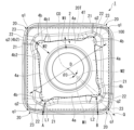
- FIG. 1 is a plan view showing one embodiment of a cutting insert 1.
- FIG. 2 is a side view showing the configuration of the cutting insert 1 shown in FIG. 1.
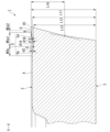
- FIG. 3 is a sectional view taken along line III--III shown in FIG.
- FIG. 4 is a cross-sectional view taken along the line IV-IV shown in FIG.
- FIG. 5 is a cross-sectional view taken along line VV shown in FIG.
- FIG. 6 is a plan view of the cutting insert shown in FIG. 1.
- FIG. 7 is a perspective view showing the configuration of an indexable rotary cutting tool including a plurality of cutting inserts and a tool body.
- FIG. 8 is a perspective view showing the structure of the tool body 31 in the indexable rotary cutting tool 30 shown in FIG. FIG.
- FIG. 1 is a plan view showing one embodiment of a cutting insert 1.
- FIG. 2 is a side view showing the configuration of the cutting insert 1 shown in FIG. 1.
- FIG. 3 is a sectional view taken along line III--III shown in FIG.
- FIG. 4 is a cross-sectional view taken along the line IV-IV shown in FIG.
- FIG. 5 is a cross-sectional view taken along line VV shown in FIG.
- FIG. 6 is a plan view of the cutting insert 1, and will be used to explain various parameters in the following paragraphs.
- FIG. 7 is a perspective view showing the configuration of an indexable rotary cutting tool 30 including a plurality of cutting inserts 1 and a tool body 31.
- FIG. 8 is a perspective view showing the structure of the tool body 31 in the indexable rotary cutting tool 30 shown in FIG.
- the cutting insert 1 of this embodiment is removably attached to the tip of the tool body 31 shown in FIG. 7 using a clamp screw (fixing member) 38 as shown in FIG. Therefore, as shown in FIG. 1, a mounting hole 7 is formed in the center of the cutting insert 1, into which a clamp screw 38 is inserted.
- the attachment hole 7 is coaxial with the center line CO, extends along the center line CO, and opens to the first plane 4 and the seating surface 3. That is, the attachment hole 7 penetrates the cutting insert 1 in the thickness direction.
- the rake face 2 is formed into a substantially square shape when viewed from the direction along the center line CO.
- the outer shape of the rake surface 2 is larger than the outer shape of the seating surface 3.
- the rake face 2 includes a first plane 4 provided around the entire circumference of the mounting hole 7, and a junction between the first plane 4 and the cutting edge portion 20 (land 6). A breaker 5 exists between the two.
- the first plane 4 is a plane parallel to the seating surface 3, and the distance from the seating surface 3 is equal to the cutting edge in the thickness direction of the cutting insert 1 (direction along the center line CO). It is a surface smaller than the portion 20 and more concave than the cutting edge portion 20.
- the first plane 4 is not connected to the cutting edge portion 20 (land 6), and its entire outer periphery is separated from the cutting edge portion 20 (land 6) toward the center line CO side.
- the breaker 5 is provided around the entire first plane 4. As shown in FIG. 1, the breaker 5 is connected to a land 6 formed on the cutting edge of the cutting edge portion 20. As shown in FIG. 3, the breaker 5 has a first inclined surface 5a that slopes toward the seating surface 3 as it goes from the cutting edge 20 toward the center line CO, and a first slope 5a that slopes toward the seating surface 3 as it goes toward the center line CO. It has a second inclined surface 5b that is inclined in the opposite direction (toward the rake surface 2), and a connecting portion 5c that connects the first inclined surface 5a and the second inclined surface 5b. The second inclined surface 5b is formed between the first inclined surface 5a and the first plane 4.
- the cutting edge portion 20 and cutting edge length used during cutting differ depending on processing conditions such as depth of cut, but in this embodiment, the breaker 5 is formed around the entire circumference of the cutting insert 1, so the cutting insert 1 No matter what machining conditions are used, chips are discharged through the breaker 5, so cutting resistance can be suppressed.
- the end of the first inclined surface 5a on the land 6 side has a multi-stage structure, but this structure may or may not be present; for example, a single-stage structure may be used. It may also be a sloped surface.
- the first inclined surface 5a has a multi-step surface 8 as shown in FIGS. 1 and 3 to 5, the angle ⁇ 1 formed by the multi-step surface 8 and the first plane 4 is always a smaller angle on the tip side of the cutting edge. For example, in FIG.
- the angle ⁇ 1B formed by the multi-step surface 8 on the cutting edge side and the first plane 4 is 5 degrees
- the angle ⁇ 1B formed between the multi-step surface 8 on the side of the first plane 4 and the first plane 4 is 5 degrees.
- the angle ⁇ 1A is 10°.
- the angle ⁇ 1 is constant over the entire circumference of the cutting insert 1. This is the same even when the first inclined surface 5a consists of a multi-step surface 8.
- the angle ⁇ 1B is 5° and the angle ⁇ 1A is 10°
- the angle ⁇ 1B is 5°
- the angle ⁇ 1A is 10°. That is, the angular relationship in FIG. 3 is also applied to FIGS. 4 and 5.
- the width of the first inclined surface 5a in the radial direction of the breaker 5 in this embodiment (the sum of the first width W5a1 and the second width W5a2) is , is preferably larger than the second width W5a2 of the second inclined surface 5b. Further, similar to the angular relationship described above, the width of the first inclined surface 5a is constant over the entire circumference of the cutting insert 1.
- the chips can be made to follow the gentle and wide first inclined surface 5a after leaving the cutting edge. Therefore, chips can be discharged while suppressing resistance caused by collision between the breaker surface and the chips.
- the width of the second inclined surface 5b in the radial direction, "the width of the first inclined surface 5a (the sum of the first width W5a1 and the second width W5a2) is secured" and "the width of the first plane 4 is secured.” It is possible to both secure the area.
- the angle ⁇ 1 between the first inclined surface 5a of the breaker 5 and the first plane 4 and the angle ⁇ 2 formed between the second inclined surface 5b and the first plane 4 may be formed to be equal.
- the angle between the first inclined surface 5a closest to the deepest part S and the first plane 4 (angle ⁇ 1A in FIGS. 3 to 5) and the angle ⁇ 2 are different. They may also be formed equally.
- the intersection ridgeline between the rake face 2 and the side surface 10 is formed by a plurality of cutting edge portions 20 including a plurality of main cutting edges 21 , a plurality of minor cutting edges 22 , and a plurality of corner edges 23 .
- the cutting edge portion 20 includes a main cutting edge 21, a minor cutting edge 22 continuous to one end side of the main cutting edge 21, and an end of the minor cutting edge 22 on the opposite side from the main cutting edge 21 side.
- the corner blade 23 is continuous with the section.
- the main cutting edge 21, the auxiliary cutting edge 22, and the corner edge 23 are arranged in this order clockwise in a plan view of the rake face 2.
- four cutting edge portions 20 each consisting of a main cutting edge 21, a minor cutting edge 22, and a corner edge 23 are provided at intervals of 90° in the circumferential direction around the center line CO. ing.
- the four cutting edges 20 are arranged rotationally symmetrically about the center line CO.
- the four cutting edge portions 20 arranged along the circumferential direction are continuous with each other.
- the corner blade 23 is located at the corner of the rake face 2.
- the corner blade 23 has an arc shape in a plan view shown in FIG.
- the main cutting edge 21 and the auxiliary cutting edge 22 extend linearly. Therefore, the boundary between the corner edge 23, the main cutting edge 21, and the auxiliary cutting edge 22 is determined by the boundary between the linear portion and the arc-shaped portion of the cutting edge portion 20.
- the auxiliary cutting edge 22 is located between the main cutting edge 21 and the corner edge 23.
- the auxiliary cutting edge 22 extends linearly between the main cutting edge 21 and the corner edge 23.
- the auxiliary cutting edge 22 extends obliquely relative to the extending direction of the main cutting edge 21 so as to approach the center line CO as it goes from the main cutting edge 21 to the corner edge 23. Therefore, the boundary between the main cutting edge 21 and the auxiliary cutting edge 22 has a shape that slightly protrudes outward.
- the cutting edge is treated to maintain the strength of the cutting edge 20, and a band-shaped land 6 is provided at the tip of each cutting edge 20.
- the plurality of lands 6 are continuous with each other and are present on the entire outer periphery of the rake face 2.
- honing may be formed in place of the land 6.
- the honing is also provided on the plurality of cutting edges 20, so that the honing is present on the entire circumference of the cutting insert 1. It is preferable to do so.
- the cutting insert 1 in this embodiment is a positive type cutting insert, as shown in FIG. It has become.
- the first cutting angle with respect to the workpiece is less than 45°.
- a boundary portion 14 is located between the upper flank surface 11 and the lower flank surface 15. That is, the side surface 10 is composed of two flank surfaces 11 and 15 separated in the thickness direction, and is divided into an upper flank surface 11 and a lower flank surface 15 by the boundary part 14. The upper flank surface 11 and the lower flank surface 15 are adjacent to each other in the direction along the center line CO of the cutting insert 1 (thickness direction).
- the upper relief surface 11 is located on the side surface 10 closer to the rake surface 2 than the boundary portion 14 .
- the lower flank surface 15 is located on the side surface 10 closer to the seating surface 3 than the boundary portion 14 .
- the distance L14 in the cross section passing through the main cutting edge 21 and the distance L15 in the cross section passing through the main cutting edge 21 satisfy the relationship L14 ⁇ L15.
- the side surface corresponding to the corner portion is arranged so that the boundary portion 14 is closer to the seating surface.
- the distance L16 in the cross section passing through the minor cutting edge 22 is shorter than L14 and L15, but as shown in FIG. It has a shape that is convex upward toward the corner blade 23 side.
- the upper flank 11 is divided into a first region 11A continuous to the main cutting edge 21, a second region 11B continuous to the auxiliary cutting edge 22, and 11C continuous to the corner edge.
- the first region 11A, the second region 11B, and the third region 11C are arranged along the circumferential direction of the center line CO.
- the side surface 10 of the cutting insert 1 is composed of two flank surfaces 11 and 15 that are separated in the thickness direction. Therefore, the degree of freedom in the shape of the cutting edge of the cutting edge portion 20 can be increased, and the area of the seating surface 3 can be increased.
- the cross-sectional shape shown in FIG. 3 is a cross-sectional shape passing through the longitudinal center of the main cutting edge 21 of the cutting edge portion 20 in FIG. 1, and is a cross-sectional shape along the line III-III in FIG. In the thickness direction at this position, the distance from the lower end of the upper flank 11 to the tip of the cutting edge portion 20 is defined as L15.
- the cross-sectional shape shown in FIG. 4 is a cross-sectional shape that passes through the normal line of the corner blade 23 of the cutting edge portion 20 in FIG. 1, and is a cross-sectional shape along the line IV-IV in FIG. In the thickness direction at this position, the distance from the lower end of the upper flank 11 to the tip of the cutting edge portion 20 is defined as L14.
- the cross-sectional shape shown in FIG. 5 is a cross section passing through the center in the length direction of the minor cutting edge 22, which is the minor cutting edge, of the cutting edge portion 20 in FIG. 1, and taken along the line VV in FIG. It has a cross-sectional shape. In the thickness direction at this position, the distance from the lower end of the upper flank 11 to the tip of the cutting edge portion 20 is defined as L16.
- the corner blade 23 of the cutting blade portion 20 is located at the farthest position from the tool rotation axis when the cutting insert 1 is attached to the tool body 31. Therefore, as shown in FIG. 4, in a cross section passing through the normal line of the corner edge 23, the cutting edge 20
- L14 ⁇ L15 the relationship between the distance L14 to the cutting edge and the distance L15 in the cross section passing through the main cutting edge 21 as L14 ⁇ L15.
- the cutting insert 1 When attaching the cutting insert 1 to the tool body 31, as shown in FIG. 7, the cutting insert 1 can be attached to the tool body 31 by tightening the clamp screw 38 to the tool body 31.
- the seating surface 3 is pressed against the insert mounting seat 33 of the tool body 31 by tightening the clamp screw 38, and the upper flank surface 11 located on the rake surface 2 side of the side surface 10 is pressed against the tool body 31.
- the tool body 31 is restrained.
- the cutting insert 1 is positioned around the axis and in the radial direction of the tool body 31.
- the first region 11A of the upper flank 11, which is close to the cutting edge 20, is restrained by the tool body 31, so that the cutting insert 1 is sufficiently firmly restrained against the cutting force applied to the cutting edge 20. becomes possible.
- the cutting insert 1 of this embodiment is a four-corner shaped insert.
- the cutting insert 1 is rotated by 90° around the center line CO so that the other cutting edge portions 20 face the workpiece. It is reattached to the tool body 31 as shown in FIG.
- a first plane 4 parallel to the seating surface 3 exists around the entire mounting hole 7.
- the first plane 4 has a smaller distance from the seating surface 3 than the cutting edge 20, and is recessed inward than the cutting edge 20.
- the first plane 4 has an outer periphery made up of linear parts 4a and protrusions 4b arranged alternately around the centerline CO.
- the linear portions 4a and the protruding portions 4b that constitute the outer periphery of the first plane 4 are provided four at a time every 90° in the circumferential direction around the center line CO.
- the four linear portions 4a have the same shape, and the four protrusions 4b also have the same shape.
- linear portions 4a and the projections 4b are arranged alternately in the circumferential direction and are continuous with each other. In the radial direction intersecting the centerline CO, each linear portion 4a faces each main cutting edge 21, and each projection 4b faces each minor cutting edge 22 and corner edge 23, respectively.
- the straight portion 4a when viewed from the axial direction perpendicular to the first plane 4, the straight portion 4a is generally straight, but the central portion in the length direction extends outward (toward the main cutting edge 21 side). It has a slightly curved shape.
- the protruding portion 4b has an arc shape centered on one or more virtual center points located on the mounting hole 7 side, and extends radially outward from the linear portion 4a toward the auxiliary cutting edge 22 and the corner edge 23. This is the part that stands out.
- the protruding portion 4b has a pair of connecting end portions 4b1 that are respectively connected to a pair of adjacent linear portions 4a on both sides in the circumferential direction.
- These pair of connecting ends 4b1 have an arc shape centered on one or more virtual center points located on the main cutting edge 21 side, and are slightly inward from the linear portion 4a toward the mounting hole 7 side. This is the recessed part.
- the protrusion 4b may have a circular arc shape with multiple curvatures, or may have a circular arc shape with a single curvature. Alternatively, it may be an arcuate shape in which short straight lines are partially mixed. In this embodiment, for example, a straight portion 4b2 exists at the apex (vertex q2 to be described later) of the protrusion 4b.
- the shortest distance from the boundary A between the circumferentially adjacent main cutting edge 21 and the sub-cutting edge 22 to the first plane 4 is L1
- the main cutting edge When the shortest distance from the boundary B between the corner blade 21 and the corner blade 23 to the first plane 4 is L2, the relationship L1 ⁇ L2 is satisfied.
- the difference between the distance L11 from the seating surface 3 to the tip of the cutting edge 20 and the distance L12 from the seating surface 3 to the first plane 4 is in the range of 0.01 mm or more and less than 0.15 mm. It is within.
Landscapes
- Engineering & Computer Science (AREA)
- Mechanical Engineering (AREA)
- Milling Processes (AREA)
Priority Applications (5)
| Application Number | Priority Date | Filing Date | Title |
|---|---|---|---|
| US18/832,531 US20250144725A1 (en) | 2022-03-08 | 2023-02-21 | Cutting insert, tool body, and edge-replaceable rotary cutting tool |
| EP23766537.7A EP4491311A4 (en) | 2022-03-08 | 2023-02-21 | CUTTING INSERTS, TOOL BODY AND REPLACEABLE EDGE ROTARY CUTTING TOOL |
| CN202380019226.3A CN118660775A (zh) | 2022-03-08 | 2023-02-21 | 切削刀片、工具主体及可转位刀片式旋转切削工具 |
| JP2024506036A JPWO2023171359A1 (https=) | 2022-03-08 | 2023-02-21 | |
| KR1020247025563A KR20240123396A (ko) | 2022-03-08 | 2023-02-21 | 절삭 인서트, 공구 본체 및 날끝 교환식 회전 절삭 공구 |
Applications Claiming Priority (2)
| Application Number | Priority Date | Filing Date | Title |
|---|---|---|---|
| JP2022-035460 | 2022-03-08 | ||
| JP2022035460 | 2022-03-08 |
Publications (1)
| Publication Number | Publication Date |
|---|---|
| WO2023171359A1 true WO2023171359A1 (ja) | 2023-09-14 |
Family
ID=87936892
Family Applications (1)
| Application Number | Title | Priority Date | Filing Date |
|---|---|---|---|
| PCT/JP2023/006128 Ceased WO2023171359A1 (ja) | 2022-03-08 | 2023-02-21 | 切削インサート、工具本体及び刃先交換式回転切削工具 |
Country Status (6)
| Country | Link |
|---|---|
| US (1) | US20250144725A1 (https=) |
| EP (1) | EP4491311A4 (https=) |
| JP (1) | JPWO2023171359A1 (https=) |
| KR (1) | KR20240123396A (https=) |
| CN (1) | CN118660775A (https=) |
| WO (1) | WO2023171359A1 (https=) |
Families Citing this family (1)
| Publication number | Priority date | Publication date | Assignee | Title |
|---|---|---|---|---|
| KR102855563B1 (ko) * | 2025-05-28 | 2025-09-05 | 주식회사 와이지-원 | 절삭 인서트 및 이를 포함하는 절삭 공구 |
Citations (3)
| Publication number | Priority date | Publication date | Assignee | Title |
|---|---|---|---|---|
| JPH10138033A (ja) | 1996-11-11 | 1998-05-26 | Toshiba Tungaloy Co Ltd | スローアウェイチップ |
| JP5287426B2 (ja) * | 2008-09-01 | 2013-09-11 | 三菱マテリアル株式会社 | 切削工具 |
| JP2022035460A (ja) | 2020-08-21 | 2022-03-04 | 株式会社日立製作所 | 超伝導線材熱処理用ボビン、超伝導線材および超伝導線材の製造方法 |
Family Cites Families (7)
| Publication number | Priority date | Publication date | Assignee | Title |
|---|---|---|---|---|
| JPH10100015A (ja) * | 1996-09-30 | 1998-04-21 | Mitsubishi Materials Corp | スローアウェイチップ |
| JP2005342871A (ja) * | 2004-06-07 | 2005-12-15 | Tungaloy Corp | スローアウェイチップ |
| CN102046313B (zh) * | 2008-06-26 | 2013-03-20 | 塞科机床公司 | 切削刀片套组、铣削刀具和切削刀片 |
| JP5952073B2 (ja) * | 2012-04-27 | 2016-07-13 | 京セラ株式会社 | 切削インサート、切削工具および被削加工物の製造方法 |
| JP2014083632A (ja) * | 2012-10-23 | 2014-05-12 | Mitsubishi Materials Corp | 切削インサート及び刃先交換式切削工具 |
| JP2017164849A (ja) * | 2016-03-16 | 2017-09-21 | 三菱日立ツール株式会社 | 切削インサート、切削インサート群、および刃先交換式切削工具 |
| JP7705024B2 (ja) * | 2021-05-11 | 2025-07-09 | 株式会社Moldino | 切削インサート及び刃先交換式回転切削工具 |
-
2023
- 2023-02-21 EP EP23766537.7A patent/EP4491311A4/en active Pending
- 2023-02-21 CN CN202380019226.3A patent/CN118660775A/zh active Pending
- 2023-02-21 JP JP2024506036A patent/JPWO2023171359A1/ja active Pending
- 2023-02-21 US US18/832,531 patent/US20250144725A1/en active Pending
- 2023-02-21 WO PCT/JP2023/006128 patent/WO2023171359A1/ja not_active Ceased
- 2023-02-21 KR KR1020247025563A patent/KR20240123396A/ko active Pending
Patent Citations (3)
| Publication number | Priority date | Publication date | Assignee | Title |
|---|---|---|---|---|
| JPH10138033A (ja) | 1996-11-11 | 1998-05-26 | Toshiba Tungaloy Co Ltd | スローアウェイチップ |
| JP5287426B2 (ja) * | 2008-09-01 | 2013-09-11 | 三菱マテリアル株式会社 | 切削工具 |
| JP2022035460A (ja) | 2020-08-21 | 2022-03-04 | 株式会社日立製作所 | 超伝導線材熱処理用ボビン、超伝導線材および超伝導線材の製造方法 |
Non-Patent Citations (1)
| Title |
|---|
| See also references of EP4491311A4 |
Also Published As
| Publication number | Publication date |
|---|---|
| US20250144725A1 (en) | 2025-05-08 |
| JPWO2023171359A1 (https=) | 2023-09-14 |
| CN118660775A (zh) | 2024-09-17 |
| KR20240123396A (ko) | 2024-08-13 |
| EP4491311A1 (en) | 2025-01-15 |
| EP4491311A4 (en) | 2026-03-18 |
Similar Documents
| Publication | Publication Date | Title |
|---|---|---|
| CN102958634B (zh) | 切削镶刀及切削工具、以及使用该切削工具的切削加工物的制造方法 | |
| JP6353941B2 (ja) | 切削インサートおよび切削工具、並びにそれを用いた切削加工物の製造方法 | |
| US7905687B2 (en) | Cutting insert, tool holder, and related method | |
| US8025465B2 (en) | Cutting insert, cutting tool and cutting method using the same | |
| JP5525615B2 (ja) | 切削インサートおよび切削工具、並びにそれらを用いた切削加工物の製造方法 | |
| CN102046314B (zh) | 具有修光刃的切削刀片 | |
| CN101668604B (zh) | 切削镶刀及切削工具以及使用了该切削工具的切削方法 | |
| KR20140106538A (ko) | 절삭 인서트 및 날끝 교환식 절삭 공구 | |
| JP6330913B2 (ja) | 切削インサート及び刃先交換式回転切削工具 | |
| JP2023539334A (ja) | 切削インサートおよび高送りフライス工具 | |
| WO2017122715A1 (ja) | 切削インサートおよび刃先交換式切削工具 | |
| US11794260B2 (en) | Milling tool | |
| JP2001198724A (ja) | スローアウェイチップ及びスローアウェイ式転削工具 | |
| CN112584953B (zh) | 球头铣刀及切削刀片 | |
| JP2014083667A (ja) | 切削インサートおよび刃先交換式切削工具 | |
| JP5197070B2 (ja) | 切削インサート及び切削工具、並びに切削方法 | |
| JP7705024B2 (ja) | 切削インサート及び刃先交換式回転切削工具 | |
| WO2023171359A1 (ja) | 切削インサート、工具本体及び刃先交換式回転切削工具 | |
| JP4821244B2 (ja) | スローアウェイチップ及びスローアウェイ式エンドミル | |
| JP5483872B2 (ja) | 切削インサートおよび切削工具ならびにそれらを用いた切削方法 | |
| JP6965754B2 (ja) | 切削インサートおよび刃先交換式切削工具 | |
| US11407043B2 (en) | Cutting insert | |
| JP2003001512A (ja) | 切削用インサート及び切削工具 | |
| EP4691675A1 (en) | Cutting insert, and indexable cutting edge type rotary cutting tool | |
| JP3744692B2 (ja) | スローアウェイ式エンドミル |
Legal Events
| Date | Code | Title | Description |
|---|---|---|---|
| 121 | Ep: the epo has been informed by wipo that ep was designated in this application |
Ref document number: 23766537 Country of ref document: EP Kind code of ref document: A1 |
|
| WWE | Wipo information: entry into national phase |
Ref document number: 18832531 Country of ref document: US |
|
| ENP | Entry into the national phase |
Ref document number: 20247025563 Country of ref document: KR Kind code of ref document: A |
|
| WWE | Wipo information: entry into national phase |
Ref document number: 202380019226.3 Country of ref document: CN |
|
| ENP | Entry into the national phase |
Ref document number: 2024506036 Country of ref document: JP Kind code of ref document: A |
|
| WWE | Wipo information: entry into national phase |
Ref document number: 2023766537 Country of ref document: EP |
|
| NENP | Non-entry into the national phase |
Ref country code: DE |
|
| ENP | Entry into the national phase |
Ref document number: 2023766537 Country of ref document: EP Effective date: 20241008 |
|
| WWP | Wipo information: published in national office |
Ref document number: 18832531 Country of ref document: US |