WO2023171183A1 - 防音材、防音構造および防音材の製造方法 - Google Patents
防音材、防音構造および防音材の製造方法 Download PDFInfo
- Publication number
- WO2023171183A1 WO2023171183A1 PCT/JP2023/003165 JP2023003165W WO2023171183A1 WO 2023171183 A1 WO2023171183 A1 WO 2023171183A1 JP 2023003165 W JP2023003165 W JP 2023003165W WO 2023171183 A1 WO2023171183 A1 WO 2023171183A1
- Authority
- WO
- WIPO (PCT)
- Prior art keywords
- layer
- foamed polyurethane
- flow resistance
- soundproofing material
- thickness direction
- Prior art date
- Legal status (The legal status is an assumption and is not a legal conclusion. Google has not performed a legal analysis and makes no representation as to the accuracy of the status listed.)
- Ceased
Links
Images



Classifications
-
- B—PERFORMING OPERATIONS; TRANSPORTING
- B29—WORKING OF PLASTICS; WORKING OF SUBSTANCES IN A PLASTIC STATE IN GENERAL
- B29C—SHAPING OR JOINING OF PLASTICS; SHAPING OF MATERIAL IN A PLASTIC STATE, NOT OTHERWISE PROVIDED FOR; AFTER-TREATMENT OF THE SHAPED PRODUCTS, e.g. REPAIRING
- B29C39/00—Shaping by casting, i.e. introducing the moulding material into a mould or between confining surfaces without significant moulding pressure; Apparatus therefor
- B29C39/22—Component parts, details or accessories; Auxiliary operations
- B29C39/44—Measuring, controlling or regulating
-
- B—PERFORMING OPERATIONS; TRANSPORTING
- B29—WORKING OF PLASTICS; WORKING OF SUBSTANCES IN A PLASTIC STATE IN GENERAL
- B29C—SHAPING OR JOINING OF PLASTICS; SHAPING OF MATERIAL IN A PLASTIC STATE, NOT OTHERWISE PROVIDED FOR; AFTER-TREATMENT OF THE SHAPED PRODUCTS, e.g. REPAIRING
- B29C44/00—Shaping by internal pressure generated in the material, e.g. swelling or foaming ; Producing porous or cellular expanded plastics articles
-
- B—PERFORMING OPERATIONS; TRANSPORTING
- B29—WORKING OF PLASTICS; WORKING OF SUBSTANCES IN A PLASTIC STATE IN GENERAL
- B29C—SHAPING OR JOINING OF PLASTICS; SHAPING OF MATERIAL IN A PLASTIC STATE, NOT OTHERWISE PROVIDED FOR; AFTER-TREATMENT OF THE SHAPED PRODUCTS, e.g. REPAIRING
- B29C44/00—Shaping by internal pressure generated in the material, e.g. swelling or foaming ; Producing porous or cellular expanded plastics articles
- B29C44/34—Auxiliary operations
- B29C44/60—Measuring, controlling or regulating
-
- G—PHYSICS
- G10—MUSICAL INSTRUMENTS; ACOUSTICS
- G10K—SOUND-PRODUCING DEVICES; METHODS OR DEVICES FOR PROTECTING AGAINST, OR FOR DAMPING, NOISE OR OTHER ACOUSTIC WAVES IN GENERAL; ACOUSTICS NOT OTHERWISE PROVIDED FOR
- G10K11/00—Methods or devices for transmitting, conducting or directing sound in general; Methods or devices for protecting against, or for damping, noise or other acoustic waves in general
- G10K11/16—Methods or devices for protecting against, or for damping, noise or other acoustic waves in general
- G10K11/162—Selection of materials
Definitions
- the present disclosure relates to a soundproofing material, a soundproofing structure, and a method of manufacturing the soundproofing material.
- Soundproofing materials are sometimes used in houses, automobiles, electrical equipment, railways, roads, etc.
- the soundproofing material is a sound-absorbing material or a sound-insulating material. Sound-absorbing materials suppress the reflection of sound waves, and sound-insulating materials suppress the transmission of sound waves.
- As a soundproofing material it is sometimes required to have both functions as a sound absorbing material and a sound insulating material.
- the sound absorbing material described in Patent Document 1 has a breathable base material and a breathable skin layer laminated on the breathable base material.
- the air permeability resistance per unit thickness of the air permeable skin layer is 20 times or more and less than 2514 times the air permeability resistance per unit thickness of the air permeable base material. It is stated that both the breathable base material and the breathable skin layer are preferably made of nonwoven fabric.
- the soundproofing material described in Patent Document 2 includes a foamed resin-based sound-absorbing layer and a fiber-based sound-absorbing layer laminated on the foamed resin-based sound-absorbing layer.
- This sound insulation material has a sound insulation layer made of a composite of foam resin and fibers at the interface between the foam resin sound absorption layer and the fiber sound absorption layer.
- the foamed resin is, for example, polyurethane
- the fibrous sound absorbing layer is, for example, felt.
- the soundproofing material described in Patent Document 3 includes, in order from the inside of the vehicle, a first breathable sound-absorbing layer, a non-breathable resin film layer, and a second breathable sound-absorbing layer.
- the first breathable sound absorbing layer and the second breathable sound absorbing layer are each a mixture of urethane foam and fibers.
- the non-air permeable resin film layer is made by laminating multiple types of resin films.
- the sound absorbing material described in Patent Document 4 consists essentially of urethane foam and fine particles inherent in the urethane foam. Fine particles are embedded in some or all of the cells of the urethane foam to form a bell-shaped structure.
- the air flow resistance value of the sound absorbing material is 30,000 to 100,000 N ⁇ s/m 4 .
- a soundproofing material As a soundproofing material, it is sometimes required to function as both a sound absorbing material and a sound insulating material. Sound-absorbing materials suppress the reflection of sound waves, and sound-insulating materials suppress the transmission of sound waves. In order to reduce the transmittance of sound waves, it is possible to increase the reflectance of sound waves, but in this case, the soundproofing material tends to reflect sound waves on its surface, making it difficult for sound waves to be absorbed from the outside into the inside through the surface, and it is difficult to absorb sound waves. rate will be low.
- One aspect of the present disclosure provides a technology that achieves both sound absorption and sound insulation properties of a foamed polyurethane layer that constitutes a soundproofing material.
- a soundproofing material is disposed facing a sound source and has a foamed polyurethane layer.
- the total thickness of the polyurethane foam layer is 4 mm or more.
- the foamed polyurethane layer has a surface layer that accounts for 20% of the total thickness of the foamed polyurethane layer from the surface facing the sound source, and a surface layer that accounts for 20% of the total thickness of the foamed polyurethane layer from the back surface that is opposite to the front surface.
- the back layer accounts for 20% of the total surface area.
- the flow resistance R1 in the thickness direction of the surface layer measured by a direct current method in accordance with ISO 9053-1:2018 is smaller than the flow resistance R2 in the thickness direction of the back layer.
- the flow resistance R1 of the surface layer of the foamed polyurethane layer is smaller than the flow resistance R2 of the back layer. Therefore, the foamed polyurethane layer easily takes in sound waves from the outside to the inside through its surface, and does not easily allow sound waves to escape from the inside to the outside through its back surface. As a result, both sound absorption and sound insulation properties can be achieved.
- FIG. 1 is a sectional view showing a soundproof structure according to one embodiment.
- FIG. 2 is a sectional view showing a soundproofing material according to one embodiment.
- FIG. 3 is a diagram showing an example of incidence, reflection, absorption, and transmission of sound waves.
- FIG. 4 is a sectional view showing a soundproofing material according to a modified example.
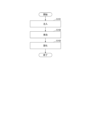
- FIG. 5 is a flowchart illustrating a method for manufacturing a soundproofing material according to one embodiment.
- FIG. 6 is a diagram showing an example of the characteristics of the foamed polyurethane layers of Examples 1 to 6.
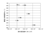
- FIG. 7 is a diagram showing another example of the characteristics of the foamed polyurethane layers of Examples 1 to 6.
- the soundproof structure 1 includes a sound source 2 and a soundproof material 3.
- the sound source 2 is, for example, an in-vehicle electrical device, specifically a motor, a battery, an inverter, or the like. Further, the sound source 2 may be noise from outside the vehicle that flows into the interior of the vehicle through the vehicle window.
- the soundproof material 3 is placed facing the sound source 2.
- the soundproofing material 3 may be arranged so as to surround the sound source 2 as shown in FIG.
- the soundproofing material 3 suppresses the transmission of sound waves propagating from the sound source 2 and also suppresses the reflection of sound waves.
- the reason why the reflection of sound waves is also suppressed is because if only the transmission of sound waves is suppressed, the sound waves will be reflected multiple times inside, and the sound waves will eventually leak to the outside. Therefore, the soundproof material 3 is required to have both functions as a sound absorbing material and a sound insulating material.
- the soundproofing material 3 includes a foamed polyurethane layer 30.
- the foamed polyurethane layer 30 contains polyurethane resin as a main component.
- Polyurethane resin is a resin that has urethane bonds in its molecules.
- the proportion of polyurethane resin in the resin constituting the foamed polyurethane layer 30 is 50% by weight to 100% by weight.
- the foamed polyurethane layer 30 is composed only of resin (organic material), but may also contain an inorganic material. The proportion of inorganic material to organic material is from 0% to 50% by weight.
- the foamed polyurethane layer 30 has a three-dimensional network skeleton.
- the foamed polyurethane layer 30 has many air bubbles inside. Many bubbles are connected to each other, and sound waves propagate inside them. At this time, air vibrates inside the foamed polyurethane layer 30. Friction occurs between the three-dimensional network skeleton of the foamed polyurethane layer 30 and the air, and sonic energy is converted into thermal energy. As a result, sound is absorbed.
- the foamed polyurethane layer 30 can improve sound absorption coefficient compared to nonwoven fabric. This is because the nonwoven fabric includes two-dimensionally oriented fibers, whereas the foamed polyurethane layer 30 has a three-dimensionally stretched network skeleton. Further, the foamed polyurethane layer 30 has a three-dimensionally stretched network skeleton and is continuously connected, so that shape retention can be improved.
- the foamed polyurethane layer 30 is a so-called polyurethane foam, and is obtained by foaming and solidifying a resin composition containing a polyisocyanate, a polyol, a catalyst, and a blowing agent.
- the blowing agent includes water. Note that the blowing agent may include a chlorine-containing compound. Details of the resin composition will be described later.
- the foamed polyurethane layer 30 has a front surface 31 facing the sound source 2 and a back surface 32 facing opposite to the front surface 31. Further, the foamed polyurethane layer 30 has a surface layer 33, an intermediate layer 34, and a back layer 35 in this order from the front surface 31 to the back surface 32.
- the surface layer 33, the intermediate layer 34, and the back layer 35 are foamed simultaneously inside the same mold, as will be described later, and have a continuous structure, that is, a seamless structure.
- the foamed polyurethane layer 30 is not formed by laminating and connecting a plurality of types of members, and has good handling properties.
- the surface layer 33 is a portion that occupies 20% of the total thickness of the foamed polyurethane layer 30 from the surface 31.
- the back layer 35 is a portion that occupies 20% of the total thickness of the foamed polyurethane layer 30 from the back surface 32.
- the intermediate layer 34 is a portion that accounts for 60% of the total thickness of the remaining foamed polyurethane layer 30.
- the overall thickness t of the foamed polyurethane layer 30 is 4 mm or more.
- the foamed polyurethane layer 30 can efficiently absorb sound waves that enter the inside from the surface 31 thereof.
- t is preferably 5 mm or more. Further, from the viewpoint of weight reduction, t is preferably 30 mm or less, more preferably 25 mm or less, and still more preferably 20 mm or less.
- FIG. 3 shows an example of the incidence, reflection, absorption, and transmission of sound waves.
- Ii represents the energy of the sound wave that enters the sound insulation material 3 from the sound source 2
- Ir represents the energy of the sound wave reflected from the sound insulation material 3 toward the sound source 2
- I ⁇ represents the energy of the sound wave that is absorbed inside the sound insulation material 3. It represents the energy of the sound wave, and It represents the energy of the sound wave that passes through the soundproofing material 3, respectively.
- the following formula (1) holds true for Ii, Ir, I ⁇ , and It.
- the sound absorption coefficient ⁇ is defined by the following formula (2).
- the sound absorption coefficient ⁇ is measured by cutting out a test piece with a thickness of 10 mm, vertically injecting a sound wave, and measuring it in accordance with JIS A1405-2:2007 "Measurement of sound absorption coefficient and impedance using an acoustic tube".
- a sound absorption coefficient ⁇ of 1.0 means that no sound is reflected at all.
- Transmittance ⁇ is defined by the following formula (3). Transmittance ⁇ is measured in accordance with ASTM E2611. A transmittance ⁇ of 1.0 means that all sound is transmitted.
- the sound transmission loss TL is defined by the following formula (4).
- the foamed polyurethane layer 30 in order for the foamed polyurethane layer 30 to independently suppress the transmission of sound waves (reduce It) and also suppress the reflection of sound waves (reduce Ir), the foamed polyurethane layer 30 must be able to pass through its surface 31 to the outside. It is important that sound waves are easily taken into the interior through the back surface 32, and that it is difficult for sound waves to escape from the inside to the outside via the back surface 32. Therefore, the inventor of the present application focused on the flow resistance of the foamed polyurethane layer 30.
- Flow resistance refers to the difficulty of air flowing through a material when air flows through the material. The greater the flow resistance, the more difficult it is for air to flow and the more difficult it is for sound to propagate. This is because sound propagates through air.
- flow resistance is measured by a direct current method based on ISO 9053-1:2018. The flow resistance is measured by dividing the foamed polyurethane layer 30 into a surface layer 33, an intermediate layer 34, and a back layer 35, and measuring the surface layer 33, intermediate layer 34, and back layer 35 separately.
- the flow resistance R1 in the thickness direction of the surface layer 33 is smaller than the flow resistance R2 in the thickness direction of the back layer 35.
- the flow resistance R2 in the thickness direction of the back layer 35 is preferably greater than 2.4 ⁇ 10 5 N ⁇ s/m 4 . If R2 is larger than 2.4 ⁇ 10 5 N ⁇ s/m 4 , it is difficult for sound waves to escape from the inside to the outside via the back surface 32 of the foamed polyurethane layer 30. Therefore, sound insulation can be improved.
- R2 is preferably 3.0 ⁇ 10 5 N ⁇ s/m 4 or more, more preferably 5.0 ⁇ 10 5 N ⁇ s/m 4 or more. From the viewpoint of productivity, R2 is preferably 2.0 ⁇ 10 6 N ⁇ s/m 4 or less.
- the flow resistance R1 in the thickness direction of the surface layer 33 is preferably 7.0 ⁇ 10 3 N ⁇ s/m 4 to 2.4 ⁇ 10 5 N ⁇ s/m 4 .
- R1 is 2.4 ⁇ 10 5 N ⁇ s/m 4 or less, sound waves easily enter the inside from the outside via the surface 31 of the foamed polyurethane layer 30.
- R1 is 7.0 ⁇ 10 3 N ⁇ s/m 4 or more, sound waves are likely to be absorbed inside the surface layer 33. Therefore, if R1 is 7.0 ⁇ 10 3 N ⁇ s/m 4 to 2.4 ⁇ 10 5 N ⁇ s/m 4 , sound absorption can be improved.
- R1 is more preferably 8.0 ⁇ 10 3 N ⁇ s/m 4 to 1.0 ⁇ 10 5 N ⁇ s/m 4 .
- the ratio (R2/R1) of the flow resistance R2 in the thickness direction of the back layer 35 to the flow resistance R1 in the thickness direction of the surface layer 33 is preferably 2 to 100. If R2/R1 is 2 or more, R1 is sufficiently smaller than R2, and sound absorption and sound insulation properties are good. If R2/R1 is 100 or less, productivity is good. R2/R1 is more preferably 3 to 50.
- the flow resistance R3 in the thickness direction of the intermediate layer 34 is preferably equal to or lower than the flow resistance R1 in the thickness direction of the surface layer 33. This allows sound waves to easily enter the interior of the intermediate layer 34 from the interface between the surface layer 33 and the intermediate layer 34. Sound waves can be easily absorbed inside the intermediate layer 34, and sound absorption can be improved.
- the ratio (R1/R3) of the flow resistance R1 in the thickness direction of the surface layer 33 to the flow resistance R3 in the thickness direction of the intermediate layer 34 is preferably 1 to 100. If R1/R3 is 1 or more, it is easy to take in sound waves into the soundproofing material 3, and the sound absorption property is good. If R1/R3 is 100 or less, productivity is good. R1/R3 is more preferably 3-60.
- the ratio (R2/R3) of the flow resistance R2 in the thickness direction of the back layer 35 to the flow resistance R3 in the thickness direction of the intermediate layer 34 is preferably 3 to 100.
- R2/R3 is 3 or more, it is difficult for sound waves to escape from the inside to the outside via the back surface 32 of the foamed polyurethane layer 30. Therefore, sound insulation can be improved. If R2/R3 is 100 or less, productivity is good.
- R2/R3 is more preferably 10-60.
- the overall sound absorption coefficient ⁇ of the foamed polyurethane layer 30 is, for example, 0.2 to 1.0, preferably 0.4 to 1.0.
- the overall sound transmission loss TL of the foamed polyurethane layer 30 is, for example, 10 dB or more and 60 dB or less, preferably 15 dB or more and 60 dB or less.
- the sound transmission loss TL of the entire foamed polyurethane layer 30 is 15 dB or more, and the sound absorption coefficient ⁇ of the entire foamed polyurethane layer is 0.4 or more, since both sound absorption and sound insulation properties can be achieved.
- the overall density of the foamed polyurethane layer 30 is, for example, 20 kg/m 3 to 140 kg/m 3 from the viewpoint of achieving both lightness and sound absorption.
- the density of the foamed polyurethane layer 30 is the so-called bulk density, and is measured in accordance with JIS K7222:2005 "Foamed plastics and rubber - How to determine apparent density.”
- the density of the foamed polyurethane layer 30 is preferably 30 kg/m 3 to 130 kg/m 3 , more preferably 55 kg/m 3 to 120 kg/m 3 .
- the soundproofing material 3 may have a reinforcing layer 39 on the back surface 32 of the foamed polyurethane layer 30.
- the reinforcing layer 39 reinforces the foamed polyurethane layer 30.
- the reinforcing layer 39 is, for example, a resin sheet, a nonwoven fabric, a coating layer, or a wood board.
- the material of the resin sheet is, for example, polyethylene terephthalate (PET), polypropylene, or polyethylene.
- PET polyethylene terephthalate
- the material of the nonwoven fabric is, for example, PET, wool, rayon, polyethylene or polypropylene.
- the wood board is, for example, particle board or laminated wood.
- the method for manufacturing the soundproof material 3 includes steps S101 to S103 in FIG. 5, for example.
- Step S101 includes injecting a resin composition into the internal space of the mold.
- the mold is a metal mold from the viewpoint of temperature controllability.
- the mold may be a sand mold, a wooden mold, or a resin mold.
- the mold is divided into, for example, a lower mold and an upper mold, and the internal space is configured to be openable and closable.
- the resin composition is injected with the inner space closed between the lower mold and the upper mold.
- the temperature of the mold is preferably adjusted to 40°C to 80°C. If the temperature of the mold is 40° C. or higher, the polymerization reaction and foaming reaction can proceed. In addition, if the temperature of the mold is 80°C or lower, these reaction rates can be moderately suppressed, and solidification can be prevented from completing before the resin is distributed throughout the interior space of the mold, thereby preventing incomplete filling. It is possible to suppress the occurrence of so-called short circuits. Note that the temperature distribution of the mold may be uniform or non-uniform. In the latter case, the polymerization reaction and foaming reaction of the resin composition can be adjusted by the temperature difference.
- the resin composition includes, for example, a polyisocyanate, a polyol, a catalyst, and a blowing agent.
- the resin composition may further contain additives.
- the resin composition is usually prepared by mixing polyisocyanate with a system liquid containing raw materials other than polyisocyanate.
- polyisocyanates examples include toluene diisocyanate (TDI), diphenylmethane diisocyanate (MDI), polymethylene polyphenylisocyanate (commonly known as crude MDI), xylylene diisocyanate (XDI), isophorone diisocyanate (IPDI), and hexamethylene diisocyanate (HMDI).
- TDI may be either 2,4-TDI or 2,6-TDI, or a mixture thereof.
- MDI may be any of 2,2'-MDI, 2,4'-MDI and 4,4'-MDI, or may be a mixture of two or three of these.
- polyols examples include polyoxyalkylene polyols, polyester polyols, and the like.
- Water can be used as the blowing agent, but is not limited thereto.
- an inert compound with a low boiling point is preferred.
- inert compounds include inert gases and saturated hydrocarbons with a boiling point of 70°C or lower and a carbon number of 8 or lower, in which hydrogen atoms bonded to carbon atoms may be substituted with halogen atoms.
- the halogen atom is, for example, a chlorine atom or a fluorine atom.
- saturated hydrocarbons include, but are not limited to, butane, pentane, hexane, dichloromethane (methylene chloride), trichloroethane, and various fluorocarbon compounds.
- one type of foaming agent may be used alone, or two or more types may be used in combination.
- the catalyst is at least one selected from the group consisting of amine catalysts and tin catalysts.
- One type of catalyst may be used alone, or two or more types may be used in combination.
- the amine catalysts include triethylenediamine, bis(2-dimethylaminoethyl)ether, N,N,N',N'-tetramethylhexamethylenediamine, N,N-dimethylaminoethoxyethoxyethanol, N,N -dimethylamino-6-hexanol, N,N-dimethylaminoethoxyethanol, a compound obtained by adding 2 moles of ethylene oxide to N,N-dimethylaminoethoxyethanol, and 5-(N,N-dimethyl)amino-3-methyl -1-pentanol, but not limited to these.
- tin-based catalysts examples include tin 2-ethylhexanoate, di-n-butyltin oxide, di-n-butyltin dilaurate, di-n-butyltin diacetate, di-n-octyltin oxide, and di-n-octyl. These include, but are not limited to, tin dilaurate, monobutyltin trichloride, di-n-butyltin dialkylmercaptan, and di-n-octyltin dialkylmercaptan.
- a foam stabilizer may be included as an additive.
- the foam stabilizer include, but are not limited to, silicone foam stabilizers and fluorine-containing compound foam stabilizers.
- One type of foam stabilizer may be used alone, or two or more types may be used in combination.
- a crosslinking agent may be included as an additive.
- a compound having two or more active hydrogen-containing groups selected from a hydroxyl group, a primary amino group, and a secondary amino group can be selected.
- polyoxyalkylene polyol having a molecular weight/number of hydroxyl groups of less than 500 as described above can also be used as a crosslinking agent.
- One type of crosslinking agent may be used alone, or two or more types may be used in combination.
- Additives other than those listed above include emulsifiers, antioxidants, anti-aging agents such as ultraviolet absorbers, fillers such as calcium carbonate or barium sulfate, plasticizers, colorants, flame retardants, anti-mold agents, and foam breakers. Examples include various known additives and auxiliaries, but the additives are not limited thereto, and additives conventionally used in polyurethane foams can be used.
- Step S102 includes foaming the resin composition in the interior space of the mold.
- Step S103 includes molding the foamed polyurethane layer 30 by solidifying the resin composition foamed in step S102.
- the foamed polyurethane layer 30 is molded to have the same shape and dimensions as the interior space of the mold. Therefore, foamed polyurethane layers 30 having the same shape and dimensions can be mass-produced. Further, since the shape and dimensions of the foamed polyurethane layer 30 are determined by the shape and dimensions of the internal space of the mold, it is possible to provide a fine structure, and cutting or bending is not necessary.
- the foamed polyurethane layer 30 is removed from the mold.
- the foamed polyurethane layer 30 is taken out, for example, with the inner space opened between the lower mold and the upper mold.
- the surface layer 33, intermediate layer 34, and back layer 35 that constitute the foamed polyurethane layer 30 are foamed simultaneously inside the same mold, and have a continuous structure, that is, a seamless structure.
- the foamed polyurethane layer 30 is not formed by laminating and connecting a plurality of types of members, and has good handling properties.
- the molding conditions are set so that the flow resistance R1 in the thickness direction of the surface layer 33 is smaller than the flow resistance R2 in the thickness direction of the back layer 35.
- R1 can be made smaller than R2 by forming different release layers on one part of the wall surface of the internal space of the mold and the other part.
- the mold release layer is formed by spraying a liquid mold release agent onto the wall surface of the mold, or by installing a mold release film on the wall surface of the mold.
- the method for manufacturing the soundproofing material 3 may include smoothing the back surface 32 of the foamed polyurethane layer 30 after the foamed polyurethane layer 30 is taken out from the mold. Smoothing the back surface 32 includes increasing the density of the back surface 32. Thereby, the flow resistance R2 of the back layer 35 can be made larger than the flow resistance R1 of the front layer 33.
- Smoothing includes, for example, pressing the back surface 32 of the foamed polyurethane layer 30 at a temperature of 30° C. or higher and a pressure of 0.01 MPa or higher.
- the pressing temperature is preferably 30°C to 260°C, more preferably 80°C to 250°C, even more preferably 100°C to 240°C. If the pressing temperature is 30° C. or higher, the back surface 32 of the foamed polyurethane layer 30 is plastically deformed, and the back surface 32 becomes smooth.
- the press pressure is preferably 0.01 MPa to 50 MPa.
- the pressing time is preferably 5 seconds to 5 minutes.
- Rmax represents the maximum value of R1, R2, and R3.
- Example 1 Basotect UF (trade name) manufactured by INOAC Co., Ltd. was prepared as the foamed polyurethane layer.
- Example 2 Calmflex F-9M (trade name, manufactured by INOAC) was prepared as the foamed polyurethane layer.
- foamed polyurethane layers were produced under the same conditions (same mold, same resin composition, same foaming conditions) except that the release layer listed in Table 1 was formed on the wall of the mold.
- the release layer was formed by spraying a liquid release agent onto the wall of the mold or by placing a release film on the wall of the mold.
- the mold release agent three types of mold release agents manufactured by Chukyo Yushi Co., Ltd. (trade names M-352, S-179, and K-878) were prepared.
- As a release sheet a paraffin film manufactured by Amcor Flexibles North America, Inc. was prepared.
- the resin composition which is the raw material for the polyurethane foam layer, was prepared by placing 109.3 parts by mass of the system liquid and 39.3 parts by mass of polyisocyanate (a mixture of TDI and MDI, manufactured by Tosoh Corporation, product name: Coronate 1021) in a container. , mixed in a high-speed mixer and prepared at room temperature.
- the system liquid includes 60 parts by mass of polyoxyalkylene polyol (manufactured by AGC, trade name: EXCENOL820), 40 parts by mass of polyoxyalkylene polyol (manufactured by AGC, trade name: EXCENOL923), and 4 parts by mass of water, which is a blowing agent.
- a foamed polyurethane layer was produced by injecting the resin composition into the interior space of the mold and foaming the resin composition in the interior space of the mold.
- the flow resistance R1 of the surface layer is smaller than the flow resistance R2 of the back layer.
- the overall sound absorption coefficient ⁇ of the foamed polyurethane layer can be increased to 0.4 or more as shown in FIG. 7. This made it possible to achieve both sound absorption and sound insulation properties.
- the sound transmission loss TL is mainly determined by the maximum value Rmax of the flow resistances R1 to R3. Also, from FIG. 6 (particularly Examples 3 and 4), it can be seen that the sound transmission loss TL does not depend on the location where the flow resistance is maximum. Examples 3 and 4 have structures in which the front and back surfaces are reversed. From FIG. 7 (particularly Examples 3 and 4), it can be seen that by employing a layer with high flow resistance as the back layer instead of the surface layer, both sound absorption and sound insulation properties can be achieved.
- the foamed polyurethane layer easily takes in sound waves from the outside to the inside through its surface, and does not easily allow sound waves to escape from the inside to the outside through its back surface.
- Soundproofing structure 1 Soundproofing structure 2 Sound source 3 Soundproofing material 30 Polyurethane foam layer 31 Front surface 32 Back surface 33 Surface layer 34 Intermediate layer 35 Back layer
Landscapes
- Physics & Mathematics (AREA)
- Engineering & Computer Science (AREA)
- Acoustics & Sound (AREA)
- Multimedia (AREA)
- Laminated Bodies (AREA)
- Casting Or Compression Moulding Of Plastics Or The Like (AREA)
Priority Applications (1)
| Application Number | Priority Date | Filing Date | Title |
|---|---|---|---|
| JP2024505947A JPWO2023171183A1 (https=) | 2022-03-08 | 2023-02-01 |
Applications Claiming Priority (2)
| Application Number | Priority Date | Filing Date | Title |
|---|---|---|---|
| JP2022035580 | 2022-03-08 | ||
| JP2022-035580 | 2022-03-08 |
Publications (1)
| Publication Number | Publication Date |
|---|---|
| WO2023171183A1 true WO2023171183A1 (ja) | 2023-09-14 |
Family
ID=87936603
Family Applications (1)
| Application Number | Title | Priority Date | Filing Date |
|---|---|---|---|
| PCT/JP2023/003165 Ceased WO2023171183A1 (ja) | 2022-03-08 | 2023-02-01 | 防音材、防音構造および防音材の製造方法 |
Country Status (2)
| Country | Link |
|---|---|
| JP (1) | JPWO2023171183A1 (https=) |
| WO (1) | WO2023171183A1 (https=) |
Citations (5)
| Publication number | Priority date | Publication date | Assignee | Title |
|---|---|---|---|---|
| JP2003300294A (ja) * | 2002-04-08 | 2003-10-21 | Basf Inoac Polyurethanes Ltd | 発泡ポリウレタン吸音材 |
| JP2005274762A (ja) * | 2004-03-23 | 2005-10-06 | Inoac Corp | 吸音材 |
| JP2005352036A (ja) * | 2004-06-09 | 2005-12-22 | Asahi Rubber Kk | 防音材およびその製造方法 |
| WO2018030441A1 (ja) * | 2016-08-12 | 2018-02-15 | 旭硝子株式会社 | 多孔質体および遮音材 |
| JP2020013007A (ja) * | 2018-07-19 | 2020-01-23 | 株式会社イノアックコーポレーション | 吸遮音材とその製造方法 |
-
2023
- 2023-02-01 WO PCT/JP2023/003165 patent/WO2023171183A1/ja not_active Ceased
- 2023-02-01 JP JP2024505947A patent/JPWO2023171183A1/ja not_active Withdrawn
Patent Citations (5)
| Publication number | Priority date | Publication date | Assignee | Title |
|---|---|---|---|---|
| JP2003300294A (ja) * | 2002-04-08 | 2003-10-21 | Basf Inoac Polyurethanes Ltd | 発泡ポリウレタン吸音材 |
| JP2005274762A (ja) * | 2004-03-23 | 2005-10-06 | Inoac Corp | 吸音材 |
| JP2005352036A (ja) * | 2004-06-09 | 2005-12-22 | Asahi Rubber Kk | 防音材およびその製造方法 |
| WO2018030441A1 (ja) * | 2016-08-12 | 2018-02-15 | 旭硝子株式会社 | 多孔質体および遮音材 |
| JP2020013007A (ja) * | 2018-07-19 | 2020-01-23 | 株式会社イノアックコーポレーション | 吸遮音材とその製造方法 |
Also Published As
| Publication number | Publication date |
|---|---|
| JPWO2023171183A1 (https=) | 2023-09-14 |
Similar Documents
| Publication | Publication Date | Title |
|---|---|---|
| KR101137527B1 (ko) | 압축 성형을 이용한 자동차용 내장재의 제조방법 | |
| JP4375985B2 (ja) | 音を減衰するために三次元的に成形される基材の製造方法 | |
| CN101331166B (zh) | 制造汽车车顶内衬的方法 | |
| JP6231186B2 (ja) | 音響吸収性が高い硬質ポリウレタンフォーム | |
| CA2653656C (en) | Composite panel | |
| JP7587620B2 (ja) | 防音材とその製造方法 | |
| CN100509902C (zh) | 软质聚氨酯泡沫塑料及其制造方法 | |
| JP2014054845A (ja) | フォーム積層体製品及びその製造方法 | |
| JP2020013007A (ja) | 吸遮音材とその製造方法 | |
| JP2025016522A (ja) | 車両用フロアサイレンサーとその製造方法 | |
| MX2010012439A (es) | Producto laminado de espuma y proceso para la produccion del mismo. | |
| WO2023171183A1 (ja) | 防音材、防音構造および防音材の製造方法 | |
| JP5986838B2 (ja) | 吸音衝撃吸収材及びその製造方法 | |
| JP2010184655A (ja) | 積層吸音材 | |
| JP7414061B2 (ja) | ポリウレタンフォーム、及び車両用防音材 | |
| JP7555202B2 (ja) | 防音材 | |
| JP7779270B2 (ja) | フェンダーライナー及びその製造方法 | |
| US20230303014A1 (en) | Fender liner, manufacturing method of fender liner, and vehicle | |
| ES2389858T3 (es) | Procedimiento para la fabricación de una pieza compuesta | |
| WO2021132387A1 (ja) | ポリウレタンフォーム、及び車両用防音材 | |
| JP7564649B2 (ja) | 防音材とその製造方法 | |
| WO2023063114A1 (ja) | フェンダーライナー及びその製造方法 | |
| CN120266200A (zh) | 隔音材料及其制造方法 | |
| JP2024033211A (ja) | 積層体と車両用天井材 | |
| WO2022113793A1 (ja) | フェンダーライナー及びその製造方法、並びに車両 |
Legal Events
| Date | Code | Title | Description |
|---|---|---|---|
| 121 | Ep: the epo has been informed by wipo that ep was designated in this application |
Ref document number: 23766363 Country of ref document: EP Kind code of ref document: A1 |
|
| ENP | Entry into the national phase |
Ref document number: 2024505947 Country of ref document: JP Kind code of ref document: A |
|
| NENP | Non-entry into the national phase |
Ref country code: DE |
|
| 122 | Ep: pct application non-entry in european phase |
Ref document number: 23766363 Country of ref document: EP Kind code of ref document: A1 |