WO2023171183A1 - 防音材、防音構造および防音材の製造方法 - Google Patents
防音材、防音構造および防音材の製造方法 Download PDFInfo
- Publication number
- WO2023171183A1 WO2023171183A1 PCT/JP2023/003165 JP2023003165W WO2023171183A1 WO 2023171183 A1 WO2023171183 A1 WO 2023171183A1 JP 2023003165 W JP2023003165 W JP 2023003165W WO 2023171183 A1 WO2023171183 A1 WO 2023171183A1
- Authority
- WO
- WIPO (PCT)
- Prior art keywords
- layer
- foamed polyurethane
- flow resistance
- soundproofing material
- thickness direction
- Prior art date
Links
Images


Classifications
-
- B—PERFORMING OPERATIONS; TRANSPORTING
- B29—WORKING OF PLASTICS; WORKING OF SUBSTANCES IN A PLASTIC STATE IN GENERAL
- B29C—SHAPING OR JOINING OF PLASTICS; SHAPING OF MATERIAL IN A PLASTIC STATE, NOT OTHERWISE PROVIDED FOR; AFTER-TREATMENT OF THE SHAPED PRODUCTS, e.g. REPAIRING
- B29C39/00—Shaping by casting, i.e. introducing the moulding material into a mould or between confining surfaces without significant moulding pressure; Apparatus therefor
- B29C39/22—Component parts, details or accessories; Auxiliary operations
- B29C39/44—Measuring, controlling or regulating
-
- B—PERFORMING OPERATIONS; TRANSPORTING
- B29—WORKING OF PLASTICS; WORKING OF SUBSTANCES IN A PLASTIC STATE IN GENERAL
- B29C—SHAPING OR JOINING OF PLASTICS; SHAPING OF MATERIAL IN A PLASTIC STATE, NOT OTHERWISE PROVIDED FOR; AFTER-TREATMENT OF THE SHAPED PRODUCTS, e.g. REPAIRING
- B29C44/00—Shaping by internal pressure generated in the material, e.g. swelling or foaming ; Producing porous or cellular expanded plastics articles
- B29C44/34—Auxiliary operations
- B29C44/60—Measuring, controlling or regulating
-
- G—PHYSICS
- G10—MUSICAL INSTRUMENTS; ACOUSTICS
- G10K—SOUND-PRODUCING DEVICES; METHODS OR DEVICES FOR PROTECTING AGAINST, OR FOR DAMPING, NOISE OR OTHER ACOUSTIC WAVES IN GENERAL; ACOUSTICS NOT OTHERWISE PROVIDED FOR
- G10K11/00—Methods or devices for transmitting, conducting or directing sound in general; Methods or devices for protecting against, or for damping, noise or other acoustic waves in general
- G10K11/16—Methods or devices for protecting against, or for damping, noise or other acoustic waves in general
- G10K11/162—Selection of materials
Definitions
- the present disclosure relates to a soundproofing material, a soundproofing structure, and a method of manufacturing the soundproofing material.
- Soundproofing materials are sometimes used in houses, automobiles, electrical equipment, railways, roads, etc.
- the soundproofing material is a sound-absorbing material or a sound-insulating material. Sound-absorbing materials suppress the reflection of sound waves, and sound-insulating materials suppress the transmission of sound waves.
- As a soundproofing material it is sometimes required to have both functions as a sound absorbing material and a sound insulating material.
- the sound absorbing material described in Patent Document 1 has a breathable base material and a breathable skin layer laminated on the breathable base material.
- the air permeability resistance per unit thickness of the air permeable skin layer is 20 times or more and less than 2514 times the air permeability resistance per unit thickness of the air permeable base material. It is stated that both the breathable base material and the breathable skin layer are preferably made of nonwoven fabric.
- the soundproofing material described in Patent Document 2 includes a foamed resin-based sound-absorbing layer and a fiber-based sound-absorbing layer laminated on the foamed resin-based sound-absorbing layer.
- This sound insulation material has a sound insulation layer made of a composite of foam resin and fibers at the interface between the foam resin sound absorption layer and the fiber sound absorption layer.
- the foamed resin is, for example, polyurethane
- the fibrous sound absorbing layer is, for example, felt.
- the soundproofing material described in Patent Document 3 includes, in order from the inside of the vehicle, a first breathable sound-absorbing layer, a non-breathable resin film layer, and a second breathable sound-absorbing layer.
- the first breathable sound absorbing layer and the second breathable sound absorbing layer are each a mixture of urethane foam and fibers.
- the non-air permeable resin film layer is made by laminating multiple types of resin films.
- the sound absorbing material described in Patent Document 4 consists essentially of urethane foam and fine particles inherent in the urethane foam. Fine particles are embedded in some or all of the cells of the urethane foam to form a bell-shaped structure.
- the air flow resistance value of the sound absorbing material is 30,000 to 100,000 N ⁇ s/m 4 .
- a soundproofing material As a soundproofing material, it is sometimes required to function as both a sound absorbing material and a sound insulating material. Sound-absorbing materials suppress the reflection of sound waves, and sound-insulating materials suppress the transmission of sound waves. In order to reduce the transmittance of sound waves, it is possible to increase the reflectance of sound waves, but in this case, the soundproofing material tends to reflect sound waves on its surface, making it difficult for sound waves to be absorbed from the outside into the inside through the surface, and it is difficult to absorb sound waves. rate will be low.
- One aspect of the present disclosure provides a technology that achieves both sound absorption and sound insulation properties of a foamed polyurethane layer that constitutes a soundproofing material.
- a soundproofing material is disposed facing a sound source and has a foamed polyurethane layer.
- the total thickness of the polyurethane foam layer is 4 mm or more.
- the foamed polyurethane layer has a surface layer that accounts for 20% of the total thickness of the foamed polyurethane layer from the surface facing the sound source, and a surface layer that accounts for 20% of the total thickness of the foamed polyurethane layer from the back surface that is opposite to the front surface.
- the back layer accounts for 20% of the total surface area.
- the flow resistance R1 in the thickness direction of the surface layer measured by a direct current method in accordance with ISO 9053-1:2018 is smaller than the flow resistance R2 in the thickness direction of the back layer.
- the flow resistance R1 of the surface layer of the foamed polyurethane layer is smaller than the flow resistance R2 of the back layer. Therefore, the foamed polyurethane layer easily takes in sound waves from the outside to the inside through its surface, and does not easily allow sound waves to escape from the inside to the outside through its back surface. As a result, both sound absorption and sound insulation properties can be achieved.
- FIG. 1 is a sectional view showing a soundproof structure according to one embodiment.
- FIG. 2 is a sectional view showing a soundproofing material according to one embodiment.
- FIG. 3 is a diagram showing an example of incidence, reflection, absorption, and transmission of sound waves.
- FIG. 4 is a sectional view showing a soundproofing material according to a modified example.
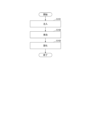
- FIG. 5 is a flowchart illustrating a method for manufacturing a soundproofing material according to one embodiment.
- FIG. 6 is a diagram showing an example of the characteristics of the foamed polyurethane layers of Examples 1 to 6.
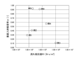
- FIG. 7 is a diagram showing another example of the characteristics of the foamed polyurethane layers of Examples 1 to 6.
- the soundproof structure 1 includes a sound source 2 and a soundproof material 3.
- the sound source 2 is, for example, an in-vehicle electrical device, specifically a motor, a battery, an inverter, or the like. Further, the sound source 2 may be noise from outside the vehicle that flows into the interior of the vehicle through the vehicle window.
- the soundproof material 3 is placed facing the sound source 2.
- the soundproofing material 3 may be arranged so as to surround the sound source 2 as shown in FIG.
- the soundproofing material 3 suppresses the transmission of sound waves propagating from the sound source 2 and also suppresses the reflection of sound waves.
- the reason why the reflection of sound waves is also suppressed is because if only the transmission of sound waves is suppressed, the sound waves will be reflected multiple times inside, and the sound waves will eventually leak to the outside. Therefore, the soundproof material 3 is required to have both functions as a sound absorbing material and a sound insulating material.
- the soundproofing material 3 includes a foamed polyurethane layer 30.
- the foamed polyurethane layer 30 contains polyurethane resin as a main component.
- Polyurethane resin is a resin that has urethane bonds in its molecules.
- the proportion of polyurethane resin in the resin constituting the foamed polyurethane layer 30 is 50% by weight to 100% by weight.
- the foamed polyurethane layer 30 is composed only of resin (organic material), but may also contain an inorganic material. The proportion of inorganic material to organic material is from 0% to 50% by weight.
- the foamed polyurethane layer 30 has a three-dimensional network skeleton.
- the foamed polyurethane layer 30 has many air bubbles inside. Many bubbles are connected to each other, and sound waves propagate inside them. At this time, air vibrates inside the foamed polyurethane layer 30. Friction occurs between the three-dimensional network skeleton of the foamed polyurethane layer 30 and the air, and sonic energy is converted into thermal energy. As a result, sound is absorbed.
- the foamed polyurethane layer 30 can improve sound absorption coefficient compared to nonwoven fabric. This is because the nonwoven fabric includes two-dimensionally oriented fibers, whereas the foamed polyurethane layer 30 has a three-dimensionally stretched network skeleton. Further, the foamed polyurethane layer 30 has a three-dimensionally stretched network skeleton and is continuously connected, so that shape retention can be improved.
- the foamed polyurethane layer 30 is a so-called polyurethane foam, and is obtained by foaming and solidifying a resin composition containing a polyisocyanate, a polyol, a catalyst, and a blowing agent.
- the blowing agent includes water. Note that the blowing agent may include a chlorine-containing compound. Details of the resin composition will be described later.
- the foamed polyurethane layer 30 has a front surface 31 facing the sound source 2 and a back surface 32 facing opposite to the front surface 31. Further, the foamed polyurethane layer 30 has a surface layer 33, an intermediate layer 34, and a back layer 35 in this order from the front surface 31 to the back surface 32.
- the surface layer 33, the intermediate layer 34, and the back layer 35 are foamed simultaneously inside the same mold, as will be described later, and have a continuous structure, that is, a seamless structure.
- the foamed polyurethane layer 30 is not formed by laminating and connecting a plurality of types of members, and has good handling properties.
- the surface layer 33 is a portion that occupies 20% of the total thickness of the foamed polyurethane layer 30 from the surface 31.
- the back layer 35 is a portion that occupies 20% of the total thickness of the foamed polyurethane layer 30 from the back surface 32.
- the intermediate layer 34 is a portion that accounts for 60% of the total thickness of the remaining foamed polyurethane layer 30.
- the overall thickness t of the foamed polyurethane layer 30 is 4 mm or more.
- the foamed polyurethane layer 30 can efficiently absorb sound waves that enter the inside from the surface 31 thereof.
- t is preferably 5 mm or more. Further, from the viewpoint of weight reduction, t is preferably 30 mm or less, more preferably 25 mm or less, and still more preferably 20 mm or less.
- FIG. 3 shows an example of the incidence, reflection, absorption, and transmission of sound waves.
- Ii represents the energy of the sound wave that enters the sound insulation material 3 from the sound source 2
- Ir represents the energy of the sound wave reflected from the sound insulation material 3 toward the sound source 2
- I ⁇ represents the energy of the sound wave that is absorbed inside the sound insulation material 3. It represents the energy of the sound wave, and It represents the energy of the sound wave that passes through the soundproofing material 3, respectively.
- the following formula (1) holds true for Ii, Ir, I ⁇ , and It.
- the sound absorption coefficient ⁇ is defined by the following formula (2).
- the sound absorption coefficient ⁇ is measured by cutting out a test piece with a thickness of 10 mm, vertically injecting a sound wave, and measuring it in accordance with JIS A1405-2:2007 "Measurement of sound absorption coefficient and impedance using an acoustic tube".
- a sound absorption coefficient ⁇ of 1.0 means that no sound is reflected at all.
- Transmittance ⁇ is defined by the following formula (3). Transmittance ⁇ is measured in accordance with ASTM E2611. A transmittance ⁇ of 1.0 means that all sound is transmitted.
- the sound transmission loss TL is defined by the following formula (4).
- the foamed polyurethane layer 30 in order for the foamed polyurethane layer 30 to independently suppress the transmission of sound waves (reduce It) and also suppress the reflection of sound waves (reduce Ir), the foamed polyurethane layer 30 must be able to pass through its surface 31 to the outside. It is important that sound waves are easily taken into the interior through the back surface 32, and that it is difficult for sound waves to escape from the inside to the outside via the back surface 32. Therefore, the inventor of the present application focused on the flow resistance of the foamed polyurethane layer 30.
- Flow resistance refers to the difficulty of air flowing through a material when air flows through the material. The greater the flow resistance, the more difficult it is for air to flow and the more difficult it is for sound to propagate. This is because sound propagates through air.
- flow resistance is measured by a direct current method based on ISO 9053-1:2018. The flow resistance is measured by dividing the foamed polyurethane layer 30 into a surface layer 33, an intermediate layer 34, and a back layer 35, and measuring the surface layer 33, intermediate layer 34, and back layer 35 separately.
- the flow resistance R1 in the thickness direction of the surface layer 33 is smaller than the flow resistance R2 in the thickness direction of the back layer 35.
- the flow resistance R2 in the thickness direction of the back layer 35 is preferably greater than 2.4 ⁇ 10 5 N ⁇ s/m 4 . If R2 is larger than 2.4 ⁇ 10 5 N ⁇ s/m 4 , it is difficult for sound waves to escape from the inside to the outside via the back surface 32 of the foamed polyurethane layer 30. Therefore, sound insulation can be improved.
- R2 is preferably 3.0 ⁇ 10 5 N ⁇ s/m 4 or more, more preferably 5.0 ⁇ 10 5 N ⁇ s/m 4 or more. From the viewpoint of productivity, R2 is preferably 2.0 ⁇ 10 6 N ⁇ s/m 4 or less.
- the flow resistance R1 in the thickness direction of the surface layer 33 is preferably 7.0 ⁇ 10 3 N ⁇ s/m 4 to 2.4 ⁇ 10 5 N ⁇ s/m 4 .
- R1 is 2.4 ⁇ 10 5 N ⁇ s/m 4 or less, sound waves easily enter the inside from the outside via the surface 31 of the foamed polyurethane layer 30.
- R1 is 7.0 ⁇ 10 3 N ⁇ s/m 4 or more, sound waves are likely to be absorbed inside the surface layer 33. Therefore, if R1 is 7.0 ⁇ 10 3 N ⁇ s/m 4 to 2.4 ⁇ 10 5 N ⁇ s/m 4 , sound absorption can be improved.
- R1 is more preferably 8.0 ⁇ 10 3 N ⁇ s/m 4 to 1.0 ⁇ 10 5 N ⁇ s/m 4 .
- the ratio (R2/R1) of the flow resistance R2 in the thickness direction of the back layer 35 to the flow resistance R1 in the thickness direction of the surface layer 33 is preferably 2 to 100. If R2/R1 is 2 or more, R1 is sufficiently smaller than R2, and sound absorption and sound insulation properties are good. If R2/R1 is 100 or less, productivity is good. R2/R1 is more preferably 3 to 50.
- the flow resistance R3 in the thickness direction of the intermediate layer 34 is preferably equal to or lower than the flow resistance R1 in the thickness direction of the surface layer 33. This allows sound waves to easily enter the interior of the intermediate layer 34 from the interface between the surface layer 33 and the intermediate layer 34. Sound waves can be easily absorbed inside the intermediate layer 34, and sound absorption can be improved.
- the ratio (R1/R3) of the flow resistance R1 in the thickness direction of the surface layer 33 to the flow resistance R3 in the thickness direction of the intermediate layer 34 is preferably 1 to 100. If R1/R3 is 1 or more, it is easy to take in sound waves into the soundproofing material 3, and the sound absorption property is good. If R1/R3 is 100 or less, productivity is good. R1/R3 is more preferably 3-60.
- the ratio (R2/R3) of the flow resistance R2 in the thickness direction of the back layer 35 to the flow resistance R3 in the thickness direction of the intermediate layer 34 is preferably 3 to 100.
- R2/R3 is 3 or more, it is difficult for sound waves to escape from the inside to the outside via the back surface 32 of the foamed polyurethane layer 30. Therefore, sound insulation can be improved. If R2/R3 is 100 or less, productivity is good.
- R2/R3 is more preferably 10-60.
- the overall sound absorption coefficient ⁇ of the foamed polyurethane layer 30 is, for example, 0.2 to 1.0, preferably 0.4 to 1.0.
- the overall sound transmission loss TL of the foamed polyurethane layer 30 is, for example, 10 dB or more and 60 dB or less, preferably 15 dB or more and 60 dB or less.
- the sound transmission loss TL of the entire foamed polyurethane layer 30 is 15 dB or more, and the sound absorption coefficient ⁇ of the entire foamed polyurethane layer is 0.4 or more, since both sound absorption and sound insulation properties can be achieved.
- the overall density of the foamed polyurethane layer 30 is, for example, 20 kg/m 3 to 140 kg/m 3 from the viewpoint of achieving both lightness and sound absorption.
- the density of the foamed polyurethane layer 30 is the so-called bulk density, and is measured in accordance with JIS K7222:2005 "Foamed plastics and rubber - How to determine apparent density.”
- the density of the foamed polyurethane layer 30 is preferably 30 kg/m 3 to 130 kg/m 3 , more preferably 55 kg/m 3 to 120 kg/m 3 .
- the soundproofing material 3 may have a reinforcing layer 39 on the back surface 32 of the foamed polyurethane layer 30.
- the reinforcing layer 39 reinforces the foamed polyurethane layer 30.
- the reinforcing layer 39 is, for example, a resin sheet, a nonwoven fabric, a coating layer, or a wood board.
- the material of the resin sheet is, for example, polyethylene terephthalate (PET), polypropylene, or polyethylene.
- PET polyethylene terephthalate
- the material of the nonwoven fabric is, for example, PET, wool, rayon, polyethylene or polypropylene.
- the wood board is, for example, particle board or laminated wood.
- the method for manufacturing the soundproof material 3 includes steps S101 to S103 in FIG. 5, for example.
- Step S101 includes injecting a resin composition into the internal space of the mold.
- the mold is a metal mold from the viewpoint of temperature controllability.
- the mold may be a sand mold, a wooden mold, or a resin mold.
- the mold is divided into, for example, a lower mold and an upper mold, and the internal space is configured to be openable and closable.
- the resin composition is injected with the inner space closed between the lower mold and the upper mold.
- the temperature of the mold is preferably adjusted to 40°C to 80°C. If the temperature of the mold is 40° C. or higher, the polymerization reaction and foaming reaction can proceed. In addition, if the temperature of the mold is 80°C or lower, these reaction rates can be moderately suppressed, and solidification can be prevented from completing before the resin is distributed throughout the interior space of the mold, thereby preventing incomplete filling. It is possible to suppress the occurrence of so-called short circuits. Note that the temperature distribution of the mold may be uniform or non-uniform. In the latter case, the polymerization reaction and foaming reaction of the resin composition can be adjusted by the temperature difference.
- the resin composition includes, for example, a polyisocyanate, a polyol, a catalyst, and a blowing agent.
- the resin composition may further contain additives.
- the resin composition is usually prepared by mixing polyisocyanate with a system liquid containing raw materials other than polyisocyanate.
- polyisocyanates examples include toluene diisocyanate (TDI), diphenylmethane diisocyanate (MDI), polymethylene polyphenylisocyanate (commonly known as crude MDI), xylylene diisocyanate (XDI), isophorone diisocyanate (IPDI), and hexamethylene diisocyanate (HMDI).
- TDI may be either 2,4-TDI or 2,6-TDI, or a mixture thereof.
- MDI may be any of 2,2'-MDI, 2,4'-MDI and 4,4'-MDI, or may be a mixture of two or three of these.
- polyols examples include polyoxyalkylene polyols, polyester polyols, and the like.
- Water can be used as the blowing agent, but is not limited thereto.
- an inert compound with a low boiling point is preferred.
- inert compounds include inert gases and saturated hydrocarbons with a boiling point of 70°C or lower and a carbon number of 8 or lower, in which hydrogen atoms bonded to carbon atoms may be substituted with halogen atoms.
- the halogen atom is, for example, a chlorine atom or a fluorine atom.
- saturated hydrocarbons include, but are not limited to, butane, pentane, hexane, dichloromethane (methylene chloride), trichloroethane, and various fluorocarbon compounds.
- one type of foaming agent may be used alone, or two or more types may be used in combination.
- the catalyst is at least one selected from the group consisting of amine catalysts and tin catalysts.
- One type of catalyst may be used alone, or two or more types may be used in combination.
- the amine catalysts include triethylenediamine, bis(2-dimethylaminoethyl)ether, N,N,N',N'-tetramethylhexamethylenediamine, N,N-dimethylaminoethoxyethoxyethanol, N,N -dimethylamino-6-hexanol, N,N-dimethylaminoethoxyethanol, a compound obtained by adding 2 moles of ethylene oxide to N,N-dimethylaminoethoxyethanol, and 5-(N,N-dimethyl)amino-3-methyl -1-pentanol, but not limited to these.
- tin-based catalysts examples include tin 2-ethylhexanoate, di-n-butyltin oxide, di-n-butyltin dilaurate, di-n-butyltin diacetate, di-n-octyltin oxide, and di-n-octyl. These include, but are not limited to, tin dilaurate, monobutyltin trichloride, di-n-butyltin dialkylmercaptan, and di-n-octyltin dialkylmercaptan.
- a foam stabilizer may be included as an additive.
- the foam stabilizer include, but are not limited to, silicone foam stabilizers and fluorine-containing compound foam stabilizers.
- One type of foam stabilizer may be used alone, or two or more types may be used in combination.
- a crosslinking agent may be included as an additive.
- a compound having two or more active hydrogen-containing groups selected from a hydroxyl group, a primary amino group, and a secondary amino group can be selected.
- polyoxyalkylene polyol having a molecular weight/number of hydroxyl groups of less than 500 as described above can also be used as a crosslinking agent.
- One type of crosslinking agent may be used alone, or two or more types may be used in combination.
- Additives other than those listed above include emulsifiers, antioxidants, anti-aging agents such as ultraviolet absorbers, fillers such as calcium carbonate or barium sulfate, plasticizers, colorants, flame retardants, anti-mold agents, and foam breakers. Examples include various known additives and auxiliaries, but the additives are not limited thereto, and additives conventionally used in polyurethane foams can be used.
- Step S102 includes foaming the resin composition in the interior space of the mold.
- Step S103 includes molding the foamed polyurethane layer 30 by solidifying the resin composition foamed in step S102.
- the foamed polyurethane layer 30 is molded to have the same shape and dimensions as the interior space of the mold. Therefore, foamed polyurethane layers 30 having the same shape and dimensions can be mass-produced. Further, since the shape and dimensions of the foamed polyurethane layer 30 are determined by the shape and dimensions of the internal space of the mold, it is possible to provide a fine structure, and cutting or bending is not necessary.
- the foamed polyurethane layer 30 is removed from the mold.
- the foamed polyurethane layer 30 is taken out, for example, with the inner space opened between the lower mold and the upper mold.
- the surface layer 33, intermediate layer 34, and back layer 35 that constitute the foamed polyurethane layer 30 are foamed simultaneously inside the same mold, and have a continuous structure, that is, a seamless structure.
- the foamed polyurethane layer 30 is not formed by laminating and connecting a plurality of types of members, and has good handling properties.
- the molding conditions are set so that the flow resistance R1 in the thickness direction of the surface layer 33 is smaller than the flow resistance R2 in the thickness direction of the back layer 35.
- R1 can be made smaller than R2 by forming different release layers on one part of the wall surface of the internal space of the mold and the other part.
- the mold release layer is formed by spraying a liquid mold release agent onto the wall surface of the mold, or by installing a mold release film on the wall surface of the mold.
- the method for manufacturing the soundproofing material 3 may include smoothing the back surface 32 of the foamed polyurethane layer 30 after the foamed polyurethane layer 30 is taken out from the mold. Smoothing the back surface 32 includes increasing the density of the back surface 32. Thereby, the flow resistance R2 of the back layer 35 can be made larger than the flow resistance R1 of the front layer 33.
- Smoothing includes, for example, pressing the back surface 32 of the foamed polyurethane layer 30 at a temperature of 30° C. or higher and a pressure of 0.01 MPa or higher.
- the pressing temperature is preferably 30°C to 260°C, more preferably 80°C to 250°C, even more preferably 100°C to 240°C. If the pressing temperature is 30° C. or higher, the back surface 32 of the foamed polyurethane layer 30 is plastically deformed, and the back surface 32 becomes smooth.
- the press pressure is preferably 0.01 MPa to 50 MPa.
- the pressing time is preferably 5 seconds to 5 minutes.
- Rmax represents the maximum value of R1, R2, and R3.
- Example 1 Basotect UF (trade name) manufactured by INOAC Co., Ltd. was prepared as the foamed polyurethane layer.
- Example 2 Calmflex F-9M (trade name, manufactured by INOAC) was prepared as the foamed polyurethane layer.
- foamed polyurethane layers were produced under the same conditions (same mold, same resin composition, same foaming conditions) except that the release layer listed in Table 1 was formed on the wall of the mold.
- the release layer was formed by spraying a liquid release agent onto the wall of the mold or by placing a release film on the wall of the mold.
- the mold release agent three types of mold release agents manufactured by Chukyo Yushi Co., Ltd. (trade names M-352, S-179, and K-878) were prepared.
- As a release sheet a paraffin film manufactured by Amcor Flexibles North America, Inc. was prepared.
- the resin composition which is the raw material for the polyurethane foam layer, was prepared by placing 109.3 parts by mass of the system liquid and 39.3 parts by mass of polyisocyanate (a mixture of TDI and MDI, manufactured by Tosoh Corporation, product name: Coronate 1021) in a container. , mixed in a high-speed mixer and prepared at room temperature.
- the system liquid includes 60 parts by mass of polyoxyalkylene polyol (manufactured by AGC, trade name: EXCENOL820), 40 parts by mass of polyoxyalkylene polyol (manufactured by AGC, trade name: EXCENOL923), and 4 parts by mass of water, which is a blowing agent.
- a foamed polyurethane layer was produced by injecting the resin composition into the interior space of the mold and foaming the resin composition in the interior space of the mold.
- the flow resistance R1 of the surface layer is smaller than the flow resistance R2 of the back layer.
- the overall sound absorption coefficient ⁇ of the foamed polyurethane layer can be increased to 0.4 or more as shown in FIG. 7. This made it possible to achieve both sound absorption and sound insulation properties.
- the sound transmission loss TL is mainly determined by the maximum value Rmax of the flow resistances R1 to R3. Also, from FIG. 6 (particularly Examples 3 and 4), it can be seen that the sound transmission loss TL does not depend on the location where the flow resistance is maximum. Examples 3 and 4 have structures in which the front and back surfaces are reversed. From FIG. 7 (particularly Examples 3 and 4), it can be seen that by employing a layer with high flow resistance as the back layer instead of the surface layer, both sound absorption and sound insulation properties can be achieved.
- the foamed polyurethane layer easily takes in sound waves from the outside to the inside through its surface, and does not easily allow sound waves to escape from the inside to the outside through its back surface.
- Soundproofing structure 1 Soundproofing structure 2 Sound source 3 Soundproofing material 30 Polyurethane foam layer 31 Front surface 32 Back surface 33 Surface layer 34 Intermediate layer 35 Back layer
Landscapes
- Physics & Mathematics (AREA)
- Engineering & Computer Science (AREA)
- Acoustics & Sound (AREA)
- Multimedia (AREA)
- Laminated Bodies (AREA)
- Casting Or Compression Moulding Of Plastics Or The Like (AREA)
Abstract
防音材は、音源に対向して配置され、発泡ポリウレタン層を有する。前記発泡ポリウレタン層の全体の厚みが4mm以上である。前記発泡ポリウレタン層は、前記音源に対向する表面から前記発泡ポリウレタン層の全体の厚みに対して20%を占める表面層と、前記表面とは反対向きの裏面から前記発泡ポリウレタン層の全体の厚みに対して20%を占める裏面層とを有する。ISO 9053-1:2018に準拠した直流法で測定した前記表面層の厚さ方向の流れ抵抗R1が、前記裏面層の厚さ方向の流れ抵抗R2よりも小さい。
Description
本開示は、防音材、防音構造および防音材の製造方法に関する。
住宅、自動車、電気機器、鉄道または道路などに、防音材が用いられることがある。防音材は、吸音材または遮音材である。吸音材は音波の反射を抑制し、遮音材は音波の透過を抑制する。防音材として、吸音材としての機能と、遮音材としての機能の両方が求められることもある。
特許文献1に記載の吸音材は、通気性基材と、通気性基材に積層した通気性表皮層とを有する。通気性表皮層の単位厚さあたりの通気抵抗が、通気性基材の単位厚さあたりの通気抵抗の20倍以上2514倍未満である。通気性基材と通気性表皮層は共に不織布であることが好ましい旨記載されている。
特許文献2に記載の防音材は、発泡樹脂系吸音層と、発泡樹脂系吸音層に積層した繊維系吸音層とを有する。この防音材は、発泡樹脂系吸音層と繊維系吸音層の界面に、発泡樹脂と繊維とを複合させた遮音層を有する。発泡樹脂は例えばポリウレタンであり、繊維系吸音層は例えばフェルトである。
特許文献3に記載の防音材は、車室内側より順番に、第1の通気性吸音層、非通気性樹脂膜層、第2の通気性吸音層と、を有する。第1の通気性吸音層と第2の通気性吸音層は、それぞれ、ウレタン発泡材と繊維の混合材である。非通気性樹脂膜層は、複数種類の樹脂フィルムを積層したものである。
特許文献4に記載の吸音材は、ウレタンフォームと、ウレタンフォームに内在する微粒子とから実質的になる。ウレタンフォームの気泡セルの一部ないし全部に、微粒子が内在して鈴状構造を構成する。吸音材の空気流れ抵抗の値が30000~100000N・s/m4である。
防音材として、吸音材としての機能と、遮音材としての機能の両方が求められることがある。吸音材は音波の反射を抑制し、遮音材は音波の透過を抑制する。音波の透過率を下げるには、音波の反射率を上げればよいが、その場合、防音材がその表面で音波を反射しやすく、表面を介して外部から内部に音波を取り込み難く、音波の吸音率が低くなってしまう。
従来、防音材の吸音性と遮音性を両立するため、特許文献1~3に記載のように複数種類の部材を積層して連結することが検討されていたが、連結するのが煩雑であり、ハンドリング性が悪かった。また、従来、1種類の部材単独で吸音性と遮音性を両立することは検討されていなかった。
本開示の一態様は、防音材を構成する発泡ポリウレタン層の吸音性と遮音性を両立する、技術を提供する。
本開示の一態様に係る防音材は、音源に対向して配置され、発泡ポリウレタン層を有する。前記発泡ポリウレタン層の全体の厚みが4mm以上である。前記発泡ポリウレタン層は、前記音源に対向する表面から前記発泡ポリウレタン層の全体の厚みに対して20%を占める表面層と、前記表面とは反対向きの裏面から前記発泡ポリウレタン層の全体の厚みに対して20%を占める裏面層とを有する。ISO 9053-1:2018に準拠した直流法で測定した前記表面層の厚さ方向の流れ抵抗R1が、前記裏面層の厚さ方向の流れ抵抗R2よりも小さい。
本開示の一態様によれば、発泡ポリウレタン層の表面層の流れ抵抗R1が裏面層の流れ抵抗R2よりも小さい。よって、発泡ポリウレタン層が、その表面を介して外部から内部に音波を取り込みやすく、且つその裏面を介して内部から外部に音波を逃がしにくい。その結果、吸音性と遮音性を両立できる。
以下、本開示の実施形態について図面を参照して説明する。なお、各図面において同一の又は対応する構成には同一の符号を付し、説明を省略することがある。また、明細書中、数値範囲を示す「~」は、その前後に記載された数値を下限値及び上限値として含むことを意味する。
先ず、図1と図2を参照して、一実施形態に係る防音構造1について説明する。防音構造1は、本実施形態では自動車に適用されるが、住宅、電気機器、鉄道または道路などに適用されてもよい。防音構造1は、音源2と、防音材3とを備える。音源2は、特に限定されないが、例えば車載用の電気機器であり、具体的にはモータ、バッテリーまたはインバータなどである。また、音源2は、車両窓を介して車内に流入する車外の騒音であってもよい。
防音材3は、音源2に対向して配置される。防音材3は、図1に示すように音源2を囲むように配置されてもよい。防音材3は、音源2から伝播する音波の透過を抑制すると共に、音波の反射も抑制する。音波の反射も抑制するのは、音波の透過を抑制するだけでは、内部で音波が多重反射してしまい、最終的に音波が外部に漏れるからである。従って、防音材3として、吸音材としての機能と、遮音材としての機能の両方が求められる。
防音材3は、発泡ポリウレタン層30を備える。発泡ポリウレタン層30は、ポリウレタン樹脂を主成分として含む。ポリウレタン樹脂は、分子中にウレタン結合を有する樹脂である。例えば、発泡ポリウレタン層30を構成する樹脂に占めるポリウレタン樹脂の割合が50重量%~100重量%である。発泡ポリウレタン層30は、樹脂(有機材料)のみで構成されるが、無機材料を含んでもよい。有機材料に対する無機材料の割合は、0重量%~50重量%である。
発泡ポリウレタン層30は、3次元的な網状の骨格を有する。発泡ポリウレタン層30は、内部に多数の気泡を有する。多数の気泡は互いにつながっており、その内部を音波が伝播する。その際に、発泡ポリウレタン層30の内部で空気が振動する。発泡ポリウレタン層30の3次元的な網状の骨格と空気との間に摩擦が生じ、音波のエネルギーが熱のエネルギーに変換される。その結果、音が吸収される。
発泡ポリウレタン層30は、不織布に比べて、吸音率を向上できる。不織布が2次元的に配向される繊維を含むのに対し、発泡ポリウレタン層30は3次元的に張り巡らされた網状の骨格を有するからである。また、発泡ポリウレタン層30は、3次元的に張り巡らされた網状の骨格を有し、連続的につながっているので、保形性を向上できる。
発泡ポリウレタン層30は、いわゆるポリウレタンフォームであって、ポリイソシアネート、ポリオール、触媒、及び発泡剤を含む樹脂組成物を発泡させ、固化して得られる。発泡剤は、水を含む。なお、発泡剤は、塩素含有化合物を含んでもよい。樹脂組成物の詳細は、後述する。
図2に示すように、発泡ポリウレタン層30は、音源2に対向する表面31と、表面31とは反対向きの裏面32とを有する。また、発泡ポリウレタン層30は、表面31から裏面32までに、表面層33と中間層34と裏面層35とをこの順番で有する。表面層33と中間層34と裏面層35とは、後述するように同一の成形型の内部で同時に発泡したものであり、連続的な構造、つまり継ぎ目の無い構造を有する。発泡ポリウレタン層30は複数種類の部材を積層して連結したものではなく、ハンドリング性が良い。
表面層33は、表面31から発泡ポリウレタン層30の全体の厚みに対して20%を占める部分のことである。裏面層35は、裏面32から発泡ポリウレタン層30の全体の厚みに対して20%を占める部分のことである。中間層34は、残りの発泡ポリウレタン層30の全体の厚みに対して60%を占める部分のことである。
発泡ポリウレタン層30の全体の厚みtは、4mm以上である。発泡ポリウレタン層30の全体の厚みが4mm以上であれば、発泡ポリウレタン層30がその表面31から内部に入り込んだ音波を効率良く吸収できる。tは、好ましくは5mm以上である。また、tは、軽量化の観点から、好ましくは30mm以下であり、より好ましくは25mm以下であり、さらに好ましくは20mm以下である。
図3に、音波の入射と反射と吸収と透過の一例を示す。図3において、Iiは音源2から防音材3に入射する音波のエネルギーを、Irは防音材3から音源2に向けて反射される音波のエネルギーを、Iδは防音材3の内部で吸収される音波のエネルギーを、Itは防音材3を透過する音波のエネルギーを、それぞれ表す。IiとIrとIδとItについて、下記式(1)が成立する。

吸音率αは、下記式(2)で定義される。吸音率αは、厚み10mmの試験片を切り出し、音波を垂直に入射し、JIS A1405-2:2007「音響管による吸音率及びインピーダンスの測定」に準拠して測定する。吸音率αが1.0であることは、音が全く反射されないことを意味する。

透過率τは、下記式(3)で定義される。透過率τは、ASTM E2611に準拠して測定する。透過率τが1.0であることは、全ての音が透過することを意味する。

音響透過損失TLは、下記式(4)で定義される。

ところで、発泡ポリウレタン層30が単独で音波の透過を抑制する(Itを小さくする)と共に音波の反射も抑制する(Irを小さくする)ためには、発泡ポリウレタン層30がその表面31を介して外部から内部に音波を取り込みやすく、且つその裏面32を介して内部から外部に音波を逃がしにくいことが重要である。そこで、本願発明者は、発泡ポリウレタン層30の流れ抵抗に着目した。
流れ抵抗は、材料に空気を流したときの材料中の空気の流れにくさを表す。流れ抵抗が大きいほど、空気が流れにくく、音も伝播しにくい。音は、空気を媒体として伝播するからである。本明細書において、流れ抵抗は、ISO 9053-1:2018に準拠した直流法で測定する。流れ抵抗は、発泡ポリウレタン層30を表面層33と中間層34と裏面層35に分割し、表面層33と中間層34と裏面層35で別々に測定する。
表面層33の厚さ方向の流れ抵抗R1は、裏面層35の厚さ方向の流れ抵抗R2よりも小さい。これにより、発泡ポリウレタン層30がその表面31を介して外部から内部に音波を取り込みやすく、且つその裏面32を介して内部から外部に音波を逃がしにくい。よって、吸音性と遮音性を両立できる。
裏面層35の厚さ方向の流れ抵抗R2は、好ましくは2.4×10⁵N・s/m4よりも大きい。R2が2.4×105N・s/m4よりも大きければ、音波が発泡ポリウレタン層30の裏面32を介して内部から外部に逃げにくい。よって、遮音性を向上できる。R2は、好ましくは3.0×105N・s/m4以上、より好ましくは5.0×105N・s/m4以上である。R2は、生産性の観点から、好ましくは2.0×106N・s/m4以下である。
表面層33の厚さ方向の流れ抵抗R1は、好ましくは7.0×10³N・s/m4~2.4×105N・s/m4である。R1が2.4×105N・s/m4以下であれば、音波が発泡ポリウレタン層30の表面31を介して外部から内部に入り込みやすい。また、R1が7.0×103N・s/m4以上であれば、表面層33の内部で音波が吸収されやすい。よって、R1が7.0×103N・s/m4~2.4×105N・s/m4であれば、吸音性を向上できる。R1は、より好ましくは8.0×103N・s/m4~1.0×105N・s/m4である。
表面層33の厚さ方向の流れ抵抗R1に対する、裏面層35の厚さ方向の流れ抵抗R2の比(R2/R1)は、好ましくは2~100である。R2/R1が2以上であれば、R1がR2よりも十分に小さく、吸音性と遮音性が良好である。R2/R1が100以下であれば、生産性が良い。R2/R1は、より好ましくは3~50である。
中間層34の厚さ方向の流れ抵抗R3は、好ましくは表面層33の厚さ方向の流れ抵抗R1以下である。これにより、音波が表面層33と中間層34の界面から中間層34の内部に入り込みやすい。中間層34の内部で音波を吸収しやすく、吸音性を向上できる。
中間層34の厚さ方向の流れ抵抗R3に対する、表面層33の厚さ方向の流れ抵抗R1の比(R1/R3)は、好ましくは1~100である。R1/R3が1以上であれば、音波を防音材3の内部へ取り込みやすく、吸音性が良好である。R1/R3が100以下であれば、生産性が良い。R1/R3は、より好ましくは3~60である。
中間層34の厚さ方向の流れ抵抗R3に対する、裏面層35の厚さ方向の流れ抵抗R2の比(R2/R3)は、好ましくは3~100である。R2/R3が3以上であれば、音波が発泡ポリウレタン層30の裏面32を介して内部から外部に逃げにくい。よって、遮音性を向上できる。R2/R3が100以下であれば、生産性が良い。R2/R3は、より好ましくは10~60である。
発泡ポリウレタン層30の全体の吸音率αは、例えば0.2~1.0であり、好ましくは0.4~1.0である。
発泡ポリウレタン層30の全体の音響透過損失TLは、例えば10dB以上60dB以下であり、好ましくは15dB以上60dB以下である。
発泡ポリウレタン層30の全体の音響透過損失TLが15dB以上であり、かつ、発泡ポリウレタン層の全体の吸音率αが0.4以上であると、吸音性と遮音性を両立でき、好ましい。
発泡ポリウレタン層30の全体の密度は、軽量性と吸音性の両立の観点から、例えば20kg/m3~140kg/m3である。発泡ポリウレタン層30の密度は、いわゆる、かさ密度であって、JIS K7222:2005「発泡プラスチック及びゴム-見掛け密度の求め方-」に準拠して測定する。発泡ポリウレタン層30の密度は、好ましくは30kg/m3~130kg/m3、より好ましくは55kg/m3~120kg/m3である。
図4に示すように、防音材3は、発泡ポリウレタン層30の裏面32に、補強層39を有してもよい。補強層39は、発泡ポリウレタン層30を補強する。補強層39は、例えば樹脂シート、不織布、コーティング層、または木材板である。樹脂シートの材質は、例えばポリエチレンテレフタレート(PET)、ポリプロピレンまたはポリエチレンである。不織布の材質は、例えばPET、羊毛、レーヨン、ポリエチレンまたはポリプロピレンである。木材板は、例えばパーティクルボードまたは集成材である。
次に、図5を参照して、一実施形態に係る防音材3の製造方法について説明する。防音材3の製造方法は、例えば図5のステップS101~S103を含む。
ステップS101は、成形型の内部空間に樹脂組成物を注入することを含む。成形型は、温度制御性の観点から、金型である。なお、成形型は、砂型、木型又は樹脂型であってもよい。成形型は、例えば下型と上型とに分割されており、内部空間を開閉可能に構成されている。樹脂組成物の注入は、下型と上型で内部空間を閉じた状態で行われる。
成形型の温度は、好ましくは40℃~80℃に調節される。成形型の温度が40℃以上であれば、重合反応、及び発泡反応を進めることができる。また、成形型の温度が80℃以下であれば、これらの反応速度を適度に抑制でき、成形型の内部空間の全体に樹脂が行き渡る前に固化が終了するのを抑制でき、不完全な充填が起きる現象、いわゆるショートの発生を抑制できる。なお、成形型の温度分布は、均一でもよいし、不均一でもよい。後者の場合、温度差によって、樹脂組成物の重合反応、及び発泡反応を調整できる。
樹脂組成物は、例えばポリイソシアネート、ポリオール、触媒、及び発泡剤を含む。樹脂組成物は、更に添加剤を含んでもよい。樹脂組成物は、通常、ポリイソシアネート以外の原料を含むシステム液と、ポリイソシアネートとを混合して調製する。
ポリイソシアネートとしては、トルエンジイソシアネート(TDI)、ジフェニルメタンジイソシアネート(MDI)、ポリメチレンポリフェニルイソシアネート(通称:クルードMDI)、キシリレンジイソシアネート(XDI)、イソホロンジイソシアネート(IPDI)及びヘキサメチレンジイソシアネート(HMDI)、これらのポリイソシアネートのプレポリマー変性体、イソシアヌレート変性体、ウレア変性体及びカルボジイミド変性体であるが、これらに限定されない。TDIは2,4-TDI及び2,6-TDIのいずれでもよく、混合物でもよい。MDIは2,2’-MDI、2,4’-MDI及び4,4’-MDIのいずれでもよく、これらのうち2種類又は3種類の混合物でもよい。
ポリオールとしては、ポリオキシアルキレンポリオール、ポリエステルポリオール等を挙げることができる。
発泡剤としては、水を用いることができるが、これに限定されない。水以外の発泡剤としては、低沸点の不活性化合物が好ましい。このような不活性化合物としては、例えば、不活性ガス、及び沸点が70℃以下で、炭素数が8以下の、炭素原子に結合する水素原子がハロゲン原子に置換されていてもよい飽和炭化水素が挙げられる。前記ハロゲン原子は、例えば、塩素原子又はフッ素原子である。飽和炭化水素の例は、ブタン、ペンタン、ヘキサン、ジクロロメタン(塩化メチレン)、トリクロロエタン及び各種フロン化合物であるが、これらに限定されない。また、発泡剤は、1種類を単独で用いてもよいし、2種類以上を併用してもよい。
触媒としては、アミン系触媒及びスズ系触媒からなる群から選択される少なくとも1種である。触媒は、1種類を単独で用いてもよいし、2種類以上を併用してもよい。前記アミン系触媒の例は、トリエチレンジアミン、ビス(2-ジメチルアミノエチル)エーテル、N,N,N’,N’-テトラメチルヘキサメチレンジアミン、N,N-ジメチルアミノエトキシエトキシエタノール、N,N-ジメチルアミノ-6-ヘキサノール、N,N-ジメチルアミノエトキシエタノール、N,N-ジメチルアミノエトキシエタノールに2モルのエチレンオキシドを付加した化合物、及び5-(N,N-ジメチル)アミノ-3-メチル-1-ペンタノールであるが、これらに限定されない。前記スズ系触媒の例は、2-エチルヘキサン酸スズ、ジ-n-ブチルスズオキシド、ジ-n-ブチルスズジラウレート、ジ-n-ブチルスズジアセテート、ジ-n-オクチルスズオキシド、ジ-n-オクチルスズジラウレート、モノブチルスズトリクロリド、ジ-n-ブチルスズジアルキルメルカプタン及びジ-n-オクチルスズジアルキルメルカプタンであるが、これらに限定されない。
添加剤として、整泡剤を含んでもよい。整泡剤の例として、シリコーン系整泡剤又は含フッ素化合物系整泡剤が挙げられるがこれらに限定されない。整泡剤は、1種類を単独で用いてもよいし、2種類以上を併用してもよい。
添加剤として、架橋剤を含んでもよい。架橋剤としては、水酸基、1級アミノ基及び2級アミノ基から選ばれる活性水素含有基を2個以上有する化合物を選択することができる。架橋剤としては、エチレングリコール、プロピレングリコール、1,4-ブタンジオール、ネオペンチルグリコール、1,6-ヘキサンジオール、ジエチレングリコール、トリエチレングリコール、ジプロピレングリコール、グリセリン、トリメチロールプロパン、ペンタエリスリトール、ジグリセリン、モノエタノールアミン、ジエタノールアミン、トリエタノールアミン、ビスフェノールA、エチレンジアミン、3,5-ジエチル-2,4-ジアミノトルエン、3,5-ジエチル-2,6-ジアミノトルエン、2-クロロ-p-フェニレンジアミン、3,5-ビス(メチルチオ)-2,4-ジアミノトルエン、3,5-ビス(メチルチオ)-2,6-ジアミノトルエン、1-トリフルオロメチル-3,5-ジアミノベンゼン、1-トリフルオロメチル-4-クロロ-3,5-ジアミノベンゼン、2,4-トルエンジアミン、2,6-トルエンジアミン、ビス(3,5-ジメチル-4-アミノフェニル)メタン、4,4’-ジアミノジフェニルメタン、m-キシリレンジアミン、1,4-ジアミノヘキサン、1,3-ビス(アミノメチル)シクロヘキサン及びイソホロンジアミンであるが、これらに限定されない。また、架橋剤として、上述した分子量/水酸基数が500未満のポリオキシアルキレンポリオールも使用できる。架橋剤は、1種類を単独で用いてもよいし、2種類以上を併用してもよい。
上記以外の添加剤としては、乳化剤、酸化防止剤、紫外線吸収剤等の老化防止剤、炭酸カルシウム又は硫酸バリウム等の充填剤、可塑剤、着色剤、難燃剤、抗カビ剤及び破泡剤等の公知の各種添加剤及び助剤が挙げられるが、これらに限定されず、従来ポリウレタンフォームに使用されている添加剤を使用できる。
ステップS102は、成形型の内部空間で樹脂組成物を発泡させることを含む。ステップS103は、ステップS102で発泡させた樹脂組成物を固化することで、発泡ポリウレタン層30を成形することを含む。発泡ポリウレタン層30は、成形型の内部空間と同一の形状及び同一の寸法に成形される。それゆえ、同一の形状及び同一の寸法を有する発泡ポリウレタン層30を大量生産できる。また、成形型の内部空間の形状及び寸法で、発泡ポリウレタン層30の形状及び寸法が決まるので、微細な構造も付与可能であり、切削加工または曲げ加工などが不要である。
その後、発泡ポリウレタン層30が、成形型から取り出される。発泡ポリウレタン層30の取り出しは、例えば、下型と上型で内部空間を開いた状態で行われる。発泡ポリウレタン層30を構成する表面層33と中間層34と裏面層35とは、同一の成形型の内部で同時に発泡したものであり、連続的な構造、つまり継ぎ目の無い構造を有する。発泡ポリウレタン層30は複数種類の部材を積層して連結したものではなく、ハンドリング性が良い。
表面層33の厚さ方向の流れ抵抗R1が裏面層35の厚さ方向の流れ抵抗R2よりも小さくなるように、成形条件が設定される。例えば、詳しくは実施例の欄で説明するが、成形型の内部空間の壁面の一部と他の一部とに異なる離型層を形成することで、R1をR2よりも小さくすることができる。離型層は、成形型の壁面に液状の離型剤をスプレーで塗布すること、または成形型の壁面に離型フィルムを設置することで形成する。
防音材3の製造方法は、発泡ポリウレタン層30を成形型から取り出した後に、発泡ポリウレタン層30の裏面32を平滑化することを含んでもよい。裏面32を平滑化することは、裏面32の密度を高めることを含む。これにより、裏面層35の流れ抵抗R2を、表面層33の流れ抵抗R1よりも大きくすることができる。
平滑化することは、例えば、発泡ポリウレタン層30の裏面32を30℃以上の温度で0.01MPa以上の圧力でプレスすることを含む。プレス温度は、好ましくは30℃~260℃、より好ましくは80℃~250℃、さらに好ましくは100℃~240℃である。プレス温度が30℃以上であれば、発泡ポリウレタン層30の裏面32が塑性変形し、裏面32が平滑になる。プレス圧力は、好ましくは0.01MPa~50MPaである。プレス時間は、好ましくは5秒~5分である。
以下、図6~図7と表1を参照して、実験データについて説明する。下記の例1~例3が比較例であり、例4~例6が実施例である。

表1において、RmaxはR1とR2とR3の最大値を表す。
例1では、発泡ポリウレタン層として、イノアック社製の商品名バソテクトUFを用意した。
例2では、発泡ポリウレタン層として、イノアック社製の商品名カームフレックスF-9Mを用意した。
例3~例6では、表1に記載の離型層を成形型の壁面に形成した以外、同じ条件(同じ成形型、同じ樹脂組成物、同じ発泡条件)で発泡ポリウレタン層を作製した。離型層は、成形型の壁面に液状の離型剤をスプレーで塗布すること、または成形型の壁面に離型フィルムを設置することで形成した。離型剤としては、中京油脂株式会社製の3種類の離型剤(商品名M-352、S-179、K-878)を用意した。離型シートとしては、Amcor Flexibles North America, Incのパラフィンフィルムを用意した。発泡ポリウレタン層の原料である樹脂組成物は、システム液を109.3質量部、ポリイソシアネート(TDIとMDIの混合物、東ソー社製、商品名:コロネート1021)を39.3質量部それぞれ容器に入れ、高速ミキサーで混合し、室温で調製したものを使用した。システム液は、ポリオキシアルキレンポリオール(AGC社製、商品名:EXCENOL820)を60質量部、ポリオキシアルキレンポリオール(AGC社製、商品名:EXCENOL923)を40質量部、発泡剤である水を4質量部、触媒(東ソー社製、商品名:TEDA L-33)を0.3質量部、触媒(東ソー社製、商品名:TOYOCAT-ET)を0.05質量部、整泡剤(Evonik社製、商品名:Tegostab B8737LF2)を3質量部、架橋剤(AGC社製、商品名:EXCENOL555)を3質量部含むものであった。成形型の内部空間に上記樹脂組成物を注入し、成形型の内部空間で上記樹脂組成物を発泡させることで、発泡ポリウレタン層を作製した。
表1に示すように、例4~例6によれば、例1~例3とは異なり、表面層の流れ抵抗R1が裏面層の流れ抵抗R2よりも小さい。その結果、図6に示すように発泡ポリウレタン層の全体の音響透過損失TLを15dB以上に維持しつつ、図7に示すように発泡ポリウレタン層の全体の吸音率αを0.4以上にすることができ、吸音性と遮音性を両立できた。
なお、図6から、音響透過損失TLは、主に流れ抵抗R1~R3の最大値Rmaxで決まることが分かる。また、図6(特に例3と例4)から、音響透過損失TLは、流れ抵抗が最大になる場所には依存しないことが分かる。例3と例4は、表面と裏面を反転した構造を有する。図7(特に例3と例4)から、流れ抵抗の大きい層を、表面層ではなく、裏面層として採用することで、吸音性と遮音性を両立できることが分かる。発泡ポリウレタン層が、その表面を介して外部から内部に音波を取り込みやすく、且つその裏面を介して内部から外部に音波を逃がしにくい。
以上、本開示に係る防音材、防音構造および防音材の製造方法の実施形態などについて説明したが、本開示は上記実施形態などに限定されない。特許請求の範囲に記載された範疇内において、各種の変更、修正、置換、付加、削除、及び組み合わせが可能である。それらについても当然に本開示の技術的範囲に属する。
本出願は、2022年3月8日に日本国特許庁に出願した特願2022-035580号に基づく優先権を主張するものであり、特願2022-035580号の全内容を本出願に援用する。
1 防音構造
2 音源
3 防音材
30 発泡ポリウレタン層
31 表面
32 裏面
33 表面層
34 中間層
35 裏面層
2 音源
3 防音材
30 発泡ポリウレタン層
31 表面
32 裏面
33 表面層
34 中間層
35 裏面層
Claims (14)
- 音源に対向して配置される防音材であって、
前記防音材が、発泡ポリウレタン層を有し、
前記発泡ポリウレタン層の全体の厚みが4mm以上であり、
前記発泡ポリウレタン層は、前記音源に対向する表面から前記発泡ポリウレタン層の全体の厚みに対して20%を占める表面層と、前記表面とは反対向きの裏面から前記発泡ポリウレタン層の全体の厚みに対して20%を占める裏面層とを有し、
ISO 9053-1:2018に準拠した直流法で測定した前記表面層の厚さ方向の流れ抵抗R1が、前記裏面層の厚さ方向の流れ抵抗R2よりも小さい、防音材。 - 前記裏面層の厚さ方向の流れ抵抗R2が、2.4×10⁵N・s/m4よりも大きい、請求項1に記載の防音材。
- 前記表面層の厚さ方向の流れ抵抗R1が、7.0×10³N・s/m4~2.4×105N・s/m4である、請求項1又は2に記載の防音材。
- 前記表面層の厚さ方向の流れ抵抗R1に対する、前記裏面層の厚さ方向の流れ抵抗R2の比(R2/R1)が2~100である、請求項1~3のいずれか1項に記載の防音材。
- 前記表面層と前記裏面層との間に、前記発泡ポリウレタン層の全体の厚みに対して60%を占める中間層を有し、
前記中間層の厚さ方向の流れ抵抗R3が、前記表面層の厚さ方向の流れ抵抗R1以下である、請求項1~4のいずれか1項に記載の防音材。 - 前記中間層の厚さ方向の流れ抵抗R3に対する、前記表面層の厚さ方向の流れ抵抗R1の比(R1/R3)が1~100である、請求項5に記載の防音材。
- 前記中間層の厚さ方向の流れ抵抗R3に対する、前記裏面層の厚さ方向の流れ抵抗R2の比(R2/R3)が3~100である、請求項5または6に記載の防音材。
- 前記発泡ポリウレタン層の前記裏面に、補強層を有する、請求項1~7のいずれか1項に記載の防音材。
- 前記発泡ポリウレタン層の全体の音響透過損失TLが15dB以上であり、かつ、前記発泡ポリウレタン層の全体の吸音率αが0.4以上である、請求項1~8のいずれか1項に記載の防音材。
- 音源と、前記音源に対向して配置される防音材とを有し、
前記防音材が、発泡ポリウレタン層を有し、
前記発泡ポリウレタン層の全体の厚みが4mm以上であり、
前記発泡ポリウレタン層は、前記音源に対向する表面から前記発泡ポリウレタン層の全体の厚みに対して20%を占める表面層と、前記表面とは反対向きの裏面から前記発泡ポリウレタン層の全体の厚みに対して20%を占める裏面層とを有し、
ISO 9053-1:2018に準拠した直流法で測定した前記表面層の厚さ方向の流れ抵抗R1が、前記裏面層の厚さ方向の流れ抵抗R2よりも小さい、防音構造。 - 請求項1~9のいずれか1項に記載の防音材を製造する、防音材の製造方法であって、
前記発泡ポリウレタン層の原料である樹脂組成物を成形型の内部空間に注入することと、
前記成形型の前記内部空間で、前記樹脂組成物を発泡させることと、
前記成形型の前記内部空間で発泡させた前記樹脂組成物を固化することで、前記発泡ポリウレタン層を成形することと、を含む、防音材の製造方法。 - 前記成形型の前記内部空間の壁面の一部と他の一部とに異なる離型層を形成した状態で、前記内部空間に前記樹脂組成物を注入することを含む、請求項11に記載の防音材の製造方法。
- 前記発泡ポリウレタン層の前記裏面を平滑化することを含む、請求項11又は12に記載の防音材の製造方法。
- 前記平滑化することは、前記発泡ポリウレタン層の前記裏面を30℃以上の温度で0.01MPa以上の圧力でプレスすることを含む、請求項13に記載の防音材の製造方法。
Applications Claiming Priority (2)
| Application Number | Priority Date | Filing Date | Title |
|---|---|---|---|
| JP2022035580 | 2022-03-08 | ||
| JP2022-035580 | 2022-03-08 |
Publications (1)
| Publication Number | Publication Date |
|---|---|
| WO2023171183A1 true WO2023171183A1 (ja) | 2023-09-14 |
Family
ID=87936603
Family Applications (1)
| Application Number | Title | Priority Date | Filing Date |
|---|---|---|---|
| PCT/JP2023/003165 WO2023171183A1 (ja) | 2022-03-08 | 2023-02-01 | 防音材、防音構造および防音材の製造方法 |
Country Status (1)
| Country | Link |
|---|---|
| WO (1) | WO2023171183A1 (ja) |
Citations (5)
| Publication number | Priority date | Publication date | Assignee | Title |
|---|---|---|---|---|
| JP2003300294A (ja) * | 2002-04-08 | 2003-10-21 | Basf Inoac Polyurethanes Ltd | 発泡ポリウレタン吸音材 |
| JP2005274762A (ja) * | 2004-03-23 | 2005-10-06 | Inoac Corp | 吸音材 |
| JP2005352036A (ja) * | 2004-06-09 | 2005-12-22 | Asahi Rubber Kk | 防音材およびその製造方法 |
| WO2018030441A1 (ja) * | 2016-08-12 | 2018-02-15 | 旭硝子株式会社 | 多孔質体および遮音材 |
| JP2020013007A (ja) * | 2018-07-19 | 2020-01-23 | 株式会社イノアックコーポレーション | 吸遮音材とその製造方法 |
-
2023
- 2023-02-01 WO PCT/JP2023/003165 patent/WO2023171183A1/ja unknown
Patent Citations (5)
| Publication number | Priority date | Publication date | Assignee | Title |
|---|---|---|---|---|
| JP2003300294A (ja) * | 2002-04-08 | 2003-10-21 | Basf Inoac Polyurethanes Ltd | 発泡ポリウレタン吸音材 |
| JP2005274762A (ja) * | 2004-03-23 | 2005-10-06 | Inoac Corp | 吸音材 |
| JP2005352036A (ja) * | 2004-06-09 | 2005-12-22 | Asahi Rubber Kk | 防音材およびその製造方法 |
| WO2018030441A1 (ja) * | 2016-08-12 | 2018-02-15 | 旭硝子株式会社 | 多孔質体および遮音材 |
| JP2020013007A (ja) * | 2018-07-19 | 2020-01-23 | 株式会社イノアックコーポレーション | 吸遮音材とその製造方法 |
Similar Documents
| Publication | Publication Date | Title |
|---|---|---|
| KR101137527B1 (ko) | 압축 성형을 이용한 자동차용 내장재의 제조방법 | |
| JP4375985B2 (ja) | 音を減衰するために三次元的に成形される基材の製造方法 | |
| EP1966266B1 (en) | Method for making automotive headliners | |
| JP6231186B2 (ja) | 音響吸収性が高い硬質ポリウレタンフォーム | |
| JP7206564B2 (ja) | 積層体及び吸音材 | |
| CA2653656C (en) | Composite panel | |
| US20080311336A1 (en) | Foam Laminate Product and Process for Production Thereof | |
| JP2014054845A (ja) | フォーム積層体製品及びその製造方法 | |
| US20080050574A1 (en) | Lower density, thermoformable, sound absorbing polyurethane foams | |
| CN102026803B (zh) | 泡沫层压产品及其生产方法 | |
| JP2020013007A (ja) | 吸遮音材とその製造方法 | |
| WO2023171183A1 (ja) | 防音材、防音構造および防音材の製造方法 | |
| JP5986838B2 (ja) | 吸音衝撃吸収材及びその製造方法 | |
| JP2010184655A (ja) | 積層吸音材 | |
| WO2022158266A1 (ja) | フェンダーライナー及びその製造方法 | |
| JP2005120247A (ja) | 自動車用防音材に使用される軟質ポリウレタンフォームおよびその製造方法 | |
| EP4245498A1 (en) | Fender liner and manufacturing method thereof, and vehicle | |
| ES2389858T3 (es) | Procedimiento para la fabricación de una pieza compuesta | |
| CN112074557A (zh) | 复合结构 | |
| JP7414061B2 (ja) | ポリウレタンフォーム、及び車両用防音材 | |
| WO2022113793A1 (ja) | フェンダーライナー及びその製造方法、並びに車両 | |
| JP7284783B2 (ja) | ウレタンフォームインシュレーター | |
| JP2024033211A (ja) | 積層体と車両用天井材 | |
| JPS63270261A (ja) | 自動車用防音構造体 | |
| JPH04368840A (ja) | 自動車内装部品前駆体の製法、内装部品の製法 |
Legal Events
| Date | Code | Title | Description |
|---|---|---|---|
| 121 | Ep: the epo has been informed by wipo that ep was designated in this application |
Ref document number: 23766363 Country of ref document: EP Kind code of ref document: A1 |