WO2023171033A1 - フェルールおよび光接続構造 - Google Patents
フェルールおよび光接続構造 Download PDFInfo
- Publication number
- WO2023171033A1 WO2023171033A1 PCT/JP2022/040960 JP2022040960W WO2023171033A1 WO 2023171033 A1 WO2023171033 A1 WO 2023171033A1 JP 2022040960 W JP2022040960 W JP 2022040960W WO 2023171033 A1 WO2023171033 A1 WO 2023171033A1
- Authority
- WO
- WIPO (PCT)
- Prior art keywords
- ferrule
- receptacle
- optical
- longitudinal direction
- longitudinal
- Prior art date
- Legal status (The legal status is an assumption and is not a legal conclusion. Google has not performed a legal analysis and makes no representation as to the accuracy of the status listed.)
- Ceased
Links
Images






Classifications
-
- G—PHYSICS
- G02—OPTICS
- G02B—OPTICAL ELEMENTS, SYSTEMS OR APPARATUS
- G02B6/00—Light guides; Structural details of arrangements comprising light guides and other optical elements, e.g. couplings
- G02B6/24—Coupling light guides
- G02B6/36—Mechanical coupling means
- G02B6/38—Mechanical coupling means having fibre to fibre mating means
- G02B6/3807—Dismountable connectors, i.e. comprising plugs
- G02B6/3873—Connectors using guide surfaces for aligning ferrule ends, e.g. tubes, sleeves, V-grooves, rods, pins, balls
- G02B6/3885—Multicore or multichannel optical connectors, i.e. one single ferrule containing more than one fibre, e.g. ribbon type
-
- G—PHYSICS
- G02—OPTICS
- G02B—OPTICAL ELEMENTS, SYSTEMS OR APPARATUS
- G02B6/00—Light guides; Structural details of arrangements comprising light guides and other optical elements, e.g. couplings
- G02B6/24—Coupling light guides
- G02B6/36—Mechanical coupling means
- G02B6/38—Mechanical coupling means having fibre to fibre mating means
- G02B6/3807—Dismountable connectors, i.e. comprising plugs
- G02B6/3833—Details of mounting fibres in ferrules; Assembly methods; Manufacture
- G02B6/3834—Means for centering or aligning the light guide within the ferrule
- G02B6/3838—Means for centering or aligning the light guide within the ferrule using grooves for light guides
- G02B6/3839—Means for centering or aligning the light guide within the ferrule using grooves for light guides for a plurality of light guides
-
- G—PHYSICS
- G02—OPTICS
- G02B—OPTICAL ELEMENTS, SYSTEMS OR APPARATUS
- G02B6/00—Light guides; Structural details of arrangements comprising light guides and other optical elements, e.g. couplings
- G02B6/24—Coupling light guides
- G02B6/26—Optical coupling means
- G02B6/30—Optical coupling means for use between fibre and thin-film device
-
- G—PHYSICS
- G02—OPTICS
- G02B—OPTICAL ELEMENTS, SYSTEMS OR APPARATUS
- G02B6/00—Light guides; Structural details of arrangements comprising light guides and other optical elements, e.g. couplings
- G02B6/24—Coupling light guides
- G02B6/36—Mechanical coupling means
- G02B6/38—Mechanical coupling means having fibre to fibre mating means
- G02B6/3807—Dismountable connectors, i.e. comprising plugs
- G02B6/3833—Details of mounting fibres in ferrules; Assembly methods; Manufacture
- G02B6/3853—Lens inside the ferrule
-
- G—PHYSICS
- G02—OPTICS
- G02B—OPTICAL ELEMENTS, SYSTEMS OR APPARATUS
- G02B6/00—Light guides; Structural details of arrangements comprising light guides and other optical elements, e.g. couplings
- G02B6/24—Coupling light guides
- G02B6/36—Mechanical coupling means
- G02B6/38—Mechanical coupling means having fibre to fibre mating means
- G02B6/3807—Dismountable connectors, i.e. comprising plugs
- G02B6/3873—Connectors using guide surfaces for aligning ferrule ends, e.g. tubes, sleeves, V-grooves, rods, pins, balls
- G02B6/3881—Connectors using guide surfaces for aligning ferrule ends, e.g. tubes, sleeves, V-grooves, rods, pins, balls using grooves to align ferrule ends
-
- G—PHYSICS
- G02—OPTICS
- G02B—OPTICAL ELEMENTS, SYSTEMS OR APPARATUS
- G02B6/00—Light guides; Structural details of arrangements comprising light guides and other optical elements, e.g. couplings
- G02B6/24—Coupling light guides
- G02B6/36—Mechanical coupling means
- G02B6/38—Mechanical coupling means having fibre to fibre mating means
- G02B6/3807—Dismountable connectors, i.e. comprising plugs
- G02B6/389—Dismountable connectors, i.e. comprising plugs characterised by the method of fastening connecting plugs and sockets, e.g. screw- or nut-lock, snap-in, bayonet type
- G02B6/3893—Push-pull type, e.g. snap-in, push-on
-
- G—PHYSICS
- G02—OPTICS
- G02B—OPTICAL ELEMENTS, SYSTEMS OR APPARATUS
- G02B6/00—Light guides; Structural details of arrangements comprising light guides and other optical elements, e.g. couplings
- G02B6/24—Coupling light guides
- G02B6/36—Mechanical coupling means
- G02B6/38—Mechanical coupling means having fibre to fibre mating means
- G02B6/3807—Dismountable connectors, i.e. comprising plugs
- G02B6/3897—Connectors fixed to housings, casing, frames or circuit boards
-
- G—PHYSICS
- G02—OPTICS
- G02B—OPTICAL ELEMENTS, SYSTEMS OR APPARATUS
- G02B6/00—Light guides; Structural details of arrangements comprising light guides and other optical elements, e.g. couplings
- G02B6/24—Coupling light guides
- G02B6/42—Coupling light guides with opto-electronic elements
- G02B6/4201—Packages, e.g. shape, construction, internal or external details
- G02B6/4219—Mechanical fixtures for holding or positioning the elements relative to each other in the couplings; Alignment methods for the elements, e.g. measuring or observing methods especially used therefor
- G02B6/4228—Passive alignment, i.e. without a detection of the degree of coupling or the position of the elements
- G02B6/423—Passive alignment, i.e. without a detection of the degree of coupling or the position of the elements using guiding surfaces for the alignment
Definitions
- the present invention relates to a ferrule and an optical connection structure.
- Patent Document 1 discloses an optical connection structure for connecting an optical element and an optical fiber.
- positioning of the optical connector in a direction perpendicular to the longitudinal direction of the optical fiber is performed using positioning pins. Further, the positioning of the optical connector in the longitudinal direction is performed by abutting the ferrule of the optical connector against the adapter.
- the outer dimensions of the ferrule are increased by the thickness of the pin. If positioning is performed using the outer shape of the ferrule without using pins, the ferrule can be made smaller.
- the inventors of the present invention have investigated that when positioning the ferrule without using pins, the arrangement of the reference plane that serves as a reference for the ferrule position in the longitudinal direction affects the quality of the optical connection using the optical connector. It was found that
- the present invention was made in consideration of these circumstances, and an object of the present invention is to provide a ferrule and an optical connection structure that can stabilize the quality of optical connections when positioning is performed without using pins.
- a ferrule according to one aspect of the present invention is a ferrule that is connected to a receptacle fixed to an optical integrated circuit, and includes a fiber hole into which an optical fiber is inserted, and a fiber hole through which the optical fiber is inserted. and a longitudinal reference surface that determines the position of the ferrule with respect to the receptacle in the longitudinal direction of the optical fiber, and the longitudinal reference surface determines the position of the ferrule in the longitudinal direction of the optical fiber. It is located between the center line passing through the center position and the light exit surface.
- the optical connection structure includes the ferrule, the receptacle, and a holding member that holds the ferrule and the receptacle in a positioned state, and the ferrule is arranged in the longitudinal direction.
- the holding member has a pressure-receiving surface that receives a biasing force in a direction intersecting with the pressure-receiving surface, and a sliding surface that is arranged apart from the pressure-receiving surface and slides on the receptacle, and the holding member applies the biasing force to the pressure-receiving surface.
- the receptacle has a receptacle-side sliding surface that slides on the sliding surface, and the receptacle-side sliding surface has a recess into which a portion of the ferrule can enter. and when the direction in which light is emitted from the light emitting surface in the longitudinal direction is the forward direction, an inclined surface is formed inside the recessed portion such that the inclined surface approaches the receptacle side sliding surface toward the front. ing.
- FIG. 2 is a diagram showing an optical connection structure according to the present embodiment.
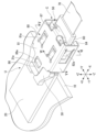
- 2 is a perspective view showing the vicinity of one optical connection unit in FIG. 1.
- FIG. FIG. 3 is an exploded perspective view of FIG. 2;
- FIG. 3B is a perspective view of the vicinity of the receptacle in FIG. 3A viewed from below.
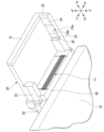
- FIG. 3B is a perspective view of the optical connector of FIG. 3A viewed from the front.
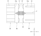
- FIG. 2 is a schematic diagram illustrating the transmission of light between an optical fiber and an optical integrated circuit in this embodiment.
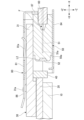
- FIG. 3 is a cross-sectional view taken along the line VV in FIG. 2; 3 is a cross-sectional view taken along the line VI-VI in FIG. 2;
- FIG. 7A is a diagram showing a state subsequent to FIG. 7A.
- FIG. FIG. 7B is a diagram showing a state following FIG. 7B.
- the optical connection structure 1 includes a substrate 10 and a plurality of optical connection units U.
- each optical connection unit U includes an optical integrated circuit 20, a receptacle 30, a microlens array 40, an optical connector C, and a holding member 80.
- the optical connector C includes a ferrule 50, a boot 60, and a tape core wire 70.
- the ferrule 50 is formed with a plurality of fiber holes 51 (see FIGS. 4 and 6) into which a plurality of optical fibers F can be inserted.
- the plurality of fiber holes 51 are arranged along one direction orthogonal to the longitudinal direction of each fiber hole 51.
- an XYZ orthogonal coordinate system is set to explain the positional relationship of each component.
- the X-axis direction is a direction along the longitudinal direction of each fiber hole 51.
- the Y-axis direction is the direction in which the plurality of fiber holes 51 are arranged.
- the Z-axis direction is a direction perpendicular to both the X-axis and the Y-axis.
- the X-axis direction is sometimes referred to as the longitudinal direction X
- the Y-axis direction is sometimes referred to as the first direction Y
- the Z-axis direction is sometimes referred to as the second direction Z.
- the direction from the ferrule 50 toward the optical integrated circuit 20 along the longitudinal direction X is referred to as the +X side or the front.
- the direction opposite to the +X side is referred to as the -X side or rearward.
- One direction along the first direction Y is referred to as the +Y side or the left side.
- the direction opposite to the +Y side is called the -Y side or right side.
- the direction from the substrate 10 toward the optical integrated circuit 20 along the second direction Z is referred to as the +Z side or upward.
- the direction opposite to the +Z side is referred to as the -Z side or downward direction.
- the tape core wire 70 is configured by covering a plurality of optical fibers F together or by intermittently fixing each other.
- the plurality of optical fibers F may not constitute the ribbon cable 70, and each optical fiber F may be individually coated.
- the boot 60 has a cylindrical shape extending in the longitudinal direction X, and the tape core wire 70 is inserted into the boot 60.
- the boot 60 is made of an elastic material and extends from the ferrule 50 toward the ⁇ X side.
- the boot 60 has the role of alleviating bending and stress applied to the optical fiber F.
- electronic components 11 are mounted on the upper surface of the board 10. Furthermore, a circuit pattern (not shown) electrically connected to the electronic component 11 is formed on the substrate 10.
- the electronic component 11 may be, for example, a switch circuit.
- the plurality of optical connection units U are arranged so as to surround the electronic component 11.
- the optical integrated circuit 20 is mounted on the upper surface of the substrate 10.
- the optical integrated circuit 20 is formed into a rectangular parallelepiped shape.
- the optical integrated circuit 20 includes a light receiving element (not shown) that converts an optical signal into an electrical signal, and a light emitting element (not shown) that converts the electrical signal into an optical signal.
- a light receiving element for example, a photodetector such as a photodiode can be used.
- As the light emitting element for example, a semiconductor laser, a light emitting diode, etc. can be used.
- the optical integrated circuit 20, the microlens array 40, and the receptacle 30 are fixed to each other with an adhesive.
- the front surface (+X side end surface) of the microlens array 40 may be adhesively fixed to the rear surface ( ⁇ X side end surface) of the optical integrated circuit 20.
- the adhesive is preferably a material that transmits light.
- the method of fixing the optical integrated circuit 20, the receptacle 30, and the microlens array 40 is not limited to the above, and may be changed as appropriate.
- the optical integrated circuit 20 has a plurality of waveguides 21. Note that in figures other than FIG. 4, illustration of the waveguide 21 is omitted.
- Each waveguide 21 is optically connected to the above-mentioned light receiving element and light emitting element.
- each waveguide 21 extends along the longitudinal direction X.
- Each waveguide 21 is made of silicon, for example.
- the refractive index of the waveguide 21 is higher than the refractive index of a portion of the optical integrated circuit 20 other than the waveguide 21 .
- the waveguide 21 may be provided on the surface (upper surface) of the optical integrated circuit 20 or may be provided inside the optical integrated circuit 20.
- an input/output section 21a is provided at the rear end (-X side end) of each waveguide 21, an input/output section 21a is provided.
- the input/output section 21a is a part of the waveguide 21, and receives and emits optical signals.
- an abutment surface 51a against which the +X side end of the optical fiber F abuts is formed inside the fiber hole 51 of the ferrule 50.
- the abutment surface 51a faces the ⁇ X side.
- the plurality of optical fibers F are respectively inserted into the plurality of fiber holes 51 and abutted against the respective abutting surfaces 51a of the fiber holes 51.
- the ferrule 50 has a lens forming surface 52 that faces the microlens array 40 in the longitudinal direction X.
- a plurality of lenses L2 arranged in the first direction Y are formed on the lens forming surface 52.
- the microlens array 40 is made of a material that can transmit light.
- the microlens array 40 may be formed of, for example, quartz glass or a silicon substrate.
- the shape of the microlens array 40 is a rectangular plate.
- a plurality of lenses L1 are formed in the microlens array 40.
- the ferrule 50 and the microlens array 40 face each other in the longitudinal direction X, as shown in FIG. More specifically, the plurality of lenses L2 formed on the ferrule 50 face the plurality of lenses L1 of the microlens array 40.
- the optical signal that has traveled within the optical fiber F toward the +X side enters the ferrule 50 from the abutment surface 51a of the fiber hole 51. Further, the optical signal is emitted from the lens L2 of the ferrule 50 to the +X side. That is, the surface of the lens L2 is a light exit surface from which light is emitted from the ferrule 50.
- the light emitted from the ferrule 50 enters the microlens array 40 through the lens L1. Further, the light passing through the microlens array 40 is received by the input/output section 21 a of the optical integrated circuit 20 and propagates through the waveguide 21 . The optical signal is then converted into an electrical signal by a light receiving element included in the optical integrated circuit 20 and delivered to the substrate 10. Conversely, an electrical signal transmitted from the substrate 10 to the optical integrated circuit 20 is converted into an optical signal by a light emitting element included in the optical integrated circuit 20. Then, this optical signal propagates through the waveguide 21 and is emitted toward the optical fiber F from the input/output section 21a. In this way, the optical connection structure 1 performs optical connection between the optical fiber F and the optical integrated circuit 20.
- the optical connector C is attached to the receptacle 30 and can be removed from the receptacle 30 (details will be described later).
- the receptacle 30 has the role of positioning the ferrule 50 of the optical connector C with respect to the optical integrated circuit 20.
- the receptacle 30 has a top wall 31, a first side wall 32, and a second side wall 33.
- the upper wall 31 has a plate shape extending in the first direction Y and the longitudinal direction X.
- the first side wall 32 extends from the +Y side end of the upper wall 31 toward the -Z side.
- the second side wall 33 extends from the -Y side end of the upper wall 31 toward the -Z side.
- the dimension of the second side wall 33 is shorter than the dimension of the first side wall 32.
- the first side wall 32 and the second side wall 33 are spaced apart in the first direction Y.
- the upper wall 31 is formed with a protrusion 31a that protrudes toward the +Z side.
- a locking portion 86 (described later) of the holding member 80 is locked to the protrusion 31a.
- the first side wall 32 has a receptacle-side sliding surface 34 facing the ⁇ Y side.
- a recess 34a is formed in the receptacle side sliding surface 34 and is recessed toward the +Y side.
- the receptacle side sliding surface 34 is divided into two parts separated in the longitudinal direction X by the recess 34a.
- an inclined surface 34b is formed inside the recess 34a.
- the inclined surface 34b is inclined toward the ⁇ Y side as it goes toward the +X side. In other words, the inclined surface 34b is inclined so as to approach the receptacle-side sliding surface 34 as it goes toward the +X side.
- a positioning surface 35 facing the -X side is formed on the first side wall 32.
- the positioning surface 35 is located on the +X side with respect to the receptacle side sliding surface 34.
- the positioning surface 35 has a role of determining the relative position of the receptacle 30 and the ferrule 50 in the longitudinal direction X.
- the second side wall 33 is also formed with a positioning surface located in the same plane as the positioning surface 35 of the first side wall 32 . The ferrule 50 is abutted against these two positioning surfaces.
- the ferrule 50 is formed into a substantially rectangular parallelepiped shape.
- the ferrule 50 is a molded product made of, for example, a transparent resin.
- the ferrule 50 includes a longitudinal reference surface 50a, a plurality of fiber holes 51 (see FIG. 4), a lens forming surface 52, a pressure receiving surface 53, a sliding surface 54, a filling hole 55, and a dustproof wall 56.
- the plurality of fiber holes 51 are lined up in the first direction Y.
- a plurality of lenses L2 are formed on the lens forming surface 52 so as to protrude toward the +X side.
- the lens forming surface 52 is the surface located on the +X side of the ferrule 50, excluding the dustproof wall 56 and the lens L2.
- each lens L2 corresponds to the position of each fiber hole 51. More specifically, when viewed from the longitudinal direction X, each lens L2 is arranged at a position overlapping each fiber hole 51.
- the dustproof wall 56 protrudes from the longitudinal reference surface 50a toward the +X side.
- the dustproof wall 56 has a rectangular frame shape when viewed from the longitudinal direction X, and surrounds the lens forming surface 52 and the lens L2.
- the dustproof wall 56 has a role of preventing dust and the like from adhering to the lens forming surface 52 and the lens L2. However, the dustproof wall 56 may not be provided.
- the filling hole 55 penetrates the ferrule 50 in the second direction Z.
- the pressure receiving surface 53 and the sliding surface 54 are both end surfaces of the ferrule 50 in the first direction Y.
- the pressure receiving surface 53 is the end surface on the -Y side
- the sliding surface 54 is the end surface on the +Y side.
- the pressure receiving surface 53 is a portion that receives a biasing force from a biasing portion 82a (described later) of the holding member 80.
- the sliding surface 54 is a part that slides on the receptacle 30. That is, when the optical connector C is connected to the receptacle 30, the ferrule 50 slides on the receptacle 30 on the sliding surface 54.
- the holding member 80 has the role of maintaining the ferrule 50 positioned in the receptacle 30.
- the holding member 80 includes an upper plate 81, a first side plate 82, a second side plate 83, a first support plate 84, a second support plate 85, and a locking portion 86.
- the holding member 80 of this embodiment is formed by molding a metal plate. However, the material, shape, and manufacturing method of the holding member 80 may be changed as appropriate.
- the holding member 80 holds the relative positions of the optical connector C and the receptacle 30
- the upper plate 81 is located on the +Z side of the receptacle 30
- the first support plate 84 and the second support plate 85 is located on the -Z side of the receptacle 30.
- the receptacle 30 and the ferrule 50 are arranged between the first side plate 82 and the second side plate 83.
- the upper plate 81 extends in the first direction Y and the longitudinal direction X.
- the first side plate 82 extends from the -Y side end of the upper plate 81 toward the -Z side.
- the second side plate 83 extends from the +Y side end of the upper plate 81 toward the -Z side.
- the second side plate 83 and the first side plate 82 face each other in the first direction Y.
- the first support plate 84 protrudes from the ⁇ Z side end of the first side plate 82 toward the +Y side.
- the second support plate 85 protrudes from the -Z side end of the second side plate 83 toward the -Y side.
- the locking portion 86 protrudes from the upper plate 81 toward the +X side.
- a through hole 86a is formed in the locking portion 86.
- the holding member 80 includes a biasing portion 82a that generates a biasing force in the first direction Y, two second biasing portions 81a that generates a biasing force in the second direction Z, and a longitudinal direction. It has a third biasing portion 87 that generates a biasing force at X.
- the biasing part 82a, the second biasing part 81a, and the third biasing part 87 of this embodiment are elastic parts (plate springs) formed in a part of the holding member 80.
- some or all of the biasing portion 82a, the second biasing portion 81a, and the third biasing portion 87 may not be plate springs, or may be composed of a separate member from the holding member 80. .
- the biasing portion 82a is formed on the first side plate 82 and biases the pressure receiving surface 53 of the ferrule 50 toward the +Y side. As shown in FIG. 5, when the ferrule 50 is biased by the biasing portion 82a, the sliding surface 54 comes into contact with the receptacle-side sliding surface 34. Thereby, the relative positions of the ferrule 50 and the receptacle 30 in the first direction Y are determined.
- the receptacle-side sliding surface 34 and the sliding surface 54 are portions that serve as a position reference in the first direction Y.
- the two second biasing parts 81a are formed on the upper plate 81.
- the number of second biasing parts 81a may be one.
- the second biasing portion 81a presses the upper wall 31 of the receptacle 30 toward the ⁇ Z side.
- the first support plate 84 and the second support plate 85 are in contact with the lower surface (-Z side end surface) of the ferrule 50 and support the ferrule 50 from the -Z side. That is, the upper wall 31 of the receptacle 30 and the ferrule 50 are sandwiched in the second direction Z between the first support plate 84, the second support plate 85, and the second biasing portion 81a.
- the lower surface of the upper wall 31 (the end surface on the ⁇ Z side) and the upper surface of the ferrule 50 (the end surface on the +Z side) are portions that serve as a position reference in the second direction Z.
- the third biasing portion 87 protrudes from the -X side end of the upper plate 81 toward the -Z side.
- the third biasing portion 87 biases the ferrule 50 toward the +X side.
- the longitudinal reference surface 50a comes into contact with the positioning surface 35.
- the longitudinal reference surface 50a and the positioning surface 35 are reference surfaces that determine the position of the ferrule 50 with respect to the receptacle 30 in the longitudinal direction X.
- a reaction force directed toward the ⁇ X side due to the urging force of the third urging portion 87 acts on the holding member 80. This reaction force is supported by the protrusion 31a of the receptacle 30 via the locking portion 86.
- positioning is performed by abutting the ferrule 50 and the receptacle 30 in three directions (X, Y, Z) without using a positioning pin.
- a positioning pin it is possible to reduce the external dimensions of the ferrule 50 (particularly the dimensions in the first direction Y). Therefore, more optical connection units U can be arranged on the board 10, and the arrangement density of optical fibers F in a data center or the like can be increased.
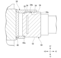
- FIG. 5 shows a center line O passing through the center of the ferrule 50 in the longitudinal direction X.
- the longitudinal reference surface 50a is located between this center line O and the lens forming surface 52 in the longitudinal direction X.
- This arrangement provides the following effects. If the longitudinal reference surface 50a is placed at the tip (+X side end) of the ferrule 50, the distance between the longitudinal reference surface 50a and the lens forming surface 52 will become too short. Therefore, when the longitudinal reference surface 50a abuts against the positioning surface 35, dust and the like tend to adhere to the lens L2. If dust or the like adheres to the lens L2, it will lead to an increase in optical connection loss between the optical integrated circuit 20 and the optical fiber F.
- the longitudinal reference surface 50a is placed at the base end (-X side end) of the ferrule 50, the distance between the longitudinal reference surface 50a and the lens L2 will be too long. Therefore, when the ferrule 50 is held with the longitudinal reference plane 50a tilted with respect to the positioning plane 35, the positional deviation of the lens L2 with respect to the lens L1 increases. In this case as well, the optical connection loss between the optical integrated circuit 20 and the optical fiber F increases.
- the longitudinal reference plane 50a between the center line O and the lens forming surface 52 as in the present embodiment, the attachment of dust to the lens L2 can be suppressed while Positional deviation with respect to L1 can also be suppressed. Therefore, when positioning the ferrule 50 without using pins, the quality of the optical connection can be stabilized.
- FIGS. 7A, 7B, and 7C the effects obtained by providing the recess 34a and the inclined surface 34b will be described using FIGS. 7A, 7B, and 7C.
- the ferrule 50 is pushed toward the +X side while sliding the sliding surface 54 of the ferrule 50 onto the receptacle-side sliding surface 34.
- the recess 34a it has been found that if the recess 34a is not provided, the connection between the optical connector C and the receptacle 30 is easily completed with the sliding surface 54 tilted with respect to the receptacle-side sliding surface 34. Ta.
- a biasing force is applied to the ferrule 50 by the biasing portion 82a, and once the sliding surface 54 is tilted with respect to the receptacle-side sliding surface 34, the biasing force is applied to maintain the tilted state. There is a possibility that it will happen.
- the biasing force directed toward the +Y side by the biasing portion 82a acts near the center of gravity of the ferrule 50, the ferrule 50 is less likely to tilt. Furthermore, the position of the contact point in the longitudinal direction X coincides with the position of the recess 34a. Therefore, the biasing force by the biasing portion 82a acts to press the sliding surface 54 in a well-balanced manner against the receptacle-side sliding surface 34 which is divided into two parts. Thereby, tilting of the ferrule 50 with respect to the receptacle 30 can be effectively suppressed.
- this embodiment provides the ferrule 50 that is connected to the receptacle 30 fixed to the optical integrated circuit 20.
- the ferrule 50 has a fiber hole 51 into which the optical fiber F is inserted, a light exit surface (the surface of the lens L2 in this embodiment) through which the light passing through the optical fiber F is emitted, and a longitudinal direction of the ferrule 50 with respect to the receptacle 30. It has a longitudinal reference surface 50a that determines the position in X.
- the longitudinal reference surface 50a is located between the center line O passing through the center position of the ferrule 50 in the longitudinal direction X and the light exit surface.
- the ferrule 50 has a lens L2 arranged at a position overlapping the fiber hole 51 when viewed from the longitudinal direction X.
- the light exit surface is the surface of the lens L2.
- the dimension between the longitudinal reference surface 50a and the light exit surface in the longitudinal direction X varies, the optical characteristics of the ferrule 50 will be affected. Therefore, the dimension between the longitudinal reference surface 50a and the light exit surface in the longitudinal direction X is required to have small manufacturing variations.
- the smaller the dimension between the longitudinal reference surface 50a and the light emitting surface that is, the closer the longitudinal reference surface 50a and the light emitting surface are in the longitudinal direction X), the easier it is to suppress manufacturing variations.
- the longitudinal reference plane 50a is located between the light exit surface (the surface of the lens L2) and the abutting surface 51a.
- the distance between the abutting surface 51a and the light exit surface is set small so that the optical signal emitted from the tip of the optical fiber F is not dispersed within the ferrule 50. Therefore, by positioning the longitudinal reference surface 50a between the light emitting surface and the abutment surface 51a, the dimension between the longitudinal reference surface 50a and the light emitting surface can be reduced, and the above-described manufacturing variations can be reduced.
- the ferrule 50 has a dustproof wall 56 that protrudes from the longitudinal reference surface 50a and surrounds the light exit surface.
- the dustproof wall 56 can more effectively suppress dust and the like from adhering to the light exit surface.
- the tip of the dustproof wall 56 the end surface on the + etc. may enter the inside of the dustproof wall 56 and adhere to the light exit surface.
- the dustproof wall 56 protrudes from the longitudinal reference surface 50a, it becomes more difficult for shavings and the like to adhere to the light emitting surface.
- the optical connection structure 1 of this embodiment includes a ferrule 50, a receptacle 30, and a holding member 80 that holds the ferrule 50 and the receptacle 30 in a positioned state.
- the ferrule 50 has a pressure receiving surface 53 that receives an urging force in a direction intersecting the longitudinal direction X of the fiber hole 51 (first direction Y in this embodiment), and is disposed apart from the pressure receiving surface 53 and slides with the receptacle 30. It has a sliding surface 54.
- the holding member 80 has a biasing portion 82a that applies a biasing force to the pressure receiving surface 53, and the receptacle 30 has a receptacle-side sliding surface 34 that slides on the sliding surface 54.
- a recess 34a into which a part of the ferrule 50 can enter is formed in the receptacle side sliding surface 34.
- An inclined surface 34b is formed.
- the receptacle side sliding surface 34 is divided into two parts in the longitudinal direction X by the recess 34a.
- the sliding surface 54 of the ferrule 50 is pressed against the receptacle-side sliding surface 34 divided into two parts, so that the tilting of the ferrule 50 can be suppressed more reliably.
- the light exit surface of the ferrule 50 may not be the surface of the lens L2.
- the surface 52 may be used as the light exit surface.
- Optical connection structure 20 Optical integrated circuit 30
- Receptacle 34 Receptacle side sliding surface 34a
- Concavity 34b ... Inclined surface 50
- Ferrule 50a Longitudinal reference surface 51
- Fiber hole 51a Abutment surface 53
- Pressure receiving surface 54 Sliding Moving surface 56
- dust-proof wall 80 ...holding member 82a...biasing part F...optical fiber
Landscapes
- Physics & Mathematics (AREA)
- General Physics & Mathematics (AREA)
- Optics & Photonics (AREA)
- Optical Couplings Of Light Guides (AREA)
Priority Applications (2)
| Application Number | Priority Date | Filing Date | Title |
|---|---|---|---|
| US18/834,452 US20250389901A1 (en) | 2022-03-09 | 2022-11-02 | Ferrule and optical connection structure |
| JP2024505887A JP7728438B2 (ja) | 2022-03-09 | 2022-11-02 | 光接続構造 |
Applications Claiming Priority (2)
| Application Number | Priority Date | Filing Date | Title |
|---|---|---|---|
| JP2022-036444 | 2022-03-09 | ||
| JP2022036444 | 2022-03-09 |
Publications (1)
| Publication Number | Publication Date |
|---|---|
| WO2023171033A1 true WO2023171033A1 (ja) | 2023-09-14 |
Family
ID=87936627
Family Applications (1)
| Application Number | Title | Priority Date | Filing Date |
|---|---|---|---|
| PCT/JP2022/040960 Ceased WO2023171033A1 (ja) | 2022-03-09 | 2022-11-02 | フェルールおよび光接続構造 |
Country Status (3)
| Country | Link |
|---|---|
| US (1) | US20250389901A1 (https=) |
| JP (1) | JP7728438B2 (https=) |
| WO (1) | WO2023171033A1 (https=) |
Citations (5)
| Publication number | Priority date | Publication date | Assignee | Title |
|---|---|---|---|---|
| CN102375181A (zh) * | 2010-08-20 | 2012-03-14 | 鸿富锦精密工业(深圳)有限公司 | 光纤耦合连接器 |
| US20130216190A1 (en) * | 2012-02-20 | 2013-08-22 | Tyco Electronics Corporation | Optical assembly with ferrule and frame |
| US20140241672A1 (en) * | 2013-02-28 | 2014-08-28 | Corning Cable Systems Llc | Liquid displacing optical coupling assemblies |
| JP2015161909A (ja) * | 2014-02-28 | 2015-09-07 | 株式会社村田製作所 | 光伝送モジュール及び光伝送モジュールの製造方法 |
| JP2016109816A (ja) * | 2014-12-04 | 2016-06-20 | 株式会社フジクラ | 光コネクタ用固定部材、光コネクタ及び光コネクタ装置 |
Family Cites Families (3)
| Publication number | Priority date | Publication date | Assignee | Title |
|---|---|---|---|---|
| JP4730274B2 (ja) | 2006-09-29 | 2011-07-20 | ソニー株式会社 | 光結合器、光コネクタ及びレセプタクル型光伝送モジュール |
| US10228520B2 (en) * | 2016-08-30 | 2019-03-12 | Corning Optical Communications LLC | Fiber-to-waveguide optical interface devices and coupling devices with lenses for photonic systems |
| WO2020086779A1 (en) * | 2018-10-23 | 2020-04-30 | Nanoprecision Products, Inc. | A demountable connection of an optical connector and an optical bench based connector using an alignment coupler |
-
2022
- 2022-11-02 US US18/834,452 patent/US20250389901A1/en active Pending
- 2022-11-02 JP JP2024505887A patent/JP7728438B2/ja active Active
- 2022-11-02 WO PCT/JP2022/040960 patent/WO2023171033A1/ja not_active Ceased
Patent Citations (5)
| Publication number | Priority date | Publication date | Assignee | Title |
|---|---|---|---|---|
| CN102375181A (zh) * | 2010-08-20 | 2012-03-14 | 鸿富锦精密工业(深圳)有限公司 | 光纤耦合连接器 |
| US20130216190A1 (en) * | 2012-02-20 | 2013-08-22 | Tyco Electronics Corporation | Optical assembly with ferrule and frame |
| US20140241672A1 (en) * | 2013-02-28 | 2014-08-28 | Corning Cable Systems Llc | Liquid displacing optical coupling assemblies |
| JP2015161909A (ja) * | 2014-02-28 | 2015-09-07 | 株式会社村田製作所 | 光伝送モジュール及び光伝送モジュールの製造方法 |
| JP2016109816A (ja) * | 2014-12-04 | 2016-06-20 | 株式会社フジクラ | 光コネクタ用固定部材、光コネクタ及び光コネクタ装置 |
Also Published As
| Publication number | Publication date |
|---|---|
| US20250389901A1 (en) | 2025-12-25 |
| JP7728438B2 (ja) | 2025-08-22 |
| JPWO2023171033A1 (https=) | 2023-09-14 |
Similar Documents
| Publication | Publication Date | Title |
|---|---|---|
| US9063304B2 (en) | Ferrule and ferrule with optical fiber | |
| US7118293B2 (en) | Optical module and manufacturing method of the same, optical communication device, opto-electrical hybrid integrated circuit, circuit board, and electronic apparatus | |
| JP3960330B2 (ja) | 光デバイスの接続構造、光デバイス、電子機器 | |
| US6987906B2 (en) | Optical connection device | |
| US8977088B2 (en) | Interposer with alignment features | |
| US6994479B2 (en) | Substrate, optical fiber connection end member, optical element housing member, and method of fabrication of an optical module and the substrate | |
| TWI507753B (zh) | Lens parts and light modules with their light | |
| US9429717B2 (en) | Ferrule and ferrule with optical fiber | |
| JP4515141B2 (ja) | 光トランシーバ | |
| US20150192745A1 (en) | Optical fiber connecter and optical communication module | |
| US9588311B2 (en) | Optical-assembly manufacturing method, optical assembly, and optical connector unit | |
| JP2003207694A (ja) | 光モジュール | |
| US9964714B2 (en) | Optical connector | |
| JP2010033088A (ja) | 光電変換素子 | |
| US20240369787A1 (en) | Optical connection structure | |
| JPWO2018042984A1 (ja) | 光接続構造 | |
| JP7728438B2 (ja) | 光接続構造 | |
| JP4657136B2 (ja) | 光送受信モジュール用ホルダ | |
| CN107209330A (zh) | 连接器以及连接器组 | |
| JP4699262B2 (ja) | 光導波路コネクタ及びそれを用いた光接続構造、並びに光導波路コネクタの製造方法 | |
| JP6898245B2 (ja) | 一体化された光デバイスを有する光学ベンチサブアセンブリ | |
| JP4807091B2 (ja) | 光伝送モジュール用コネクタ構造 | |
| JP5010023B2 (ja) | 光導波路コネクタ及びそれを用いた光接続構造、並びに光導波路コネクタの製造方法 | |
| JP2006065358A (ja) | 光モジュール、パッケージおよび光ファイバコネクタ | |
| JP2017040703A (ja) | 光モジュール及び光モジュール用レセプタクル |
Legal Events
| Date | Code | Title | Description |
|---|---|---|---|
| 121 | Ep: the epo has been informed by wipo that ep was designated in this application |
Ref document number: 22931007 Country of ref document: EP Kind code of ref document: A1 |
|
| ENP | Entry into the national phase |
Ref document number: 2024505887 Country of ref document: JP Kind code of ref document: A |
|
| NENP | Non-entry into the national phase |
Ref country code: DE |
|
| 122 | Ep: pct application non-entry in european phase |
Ref document number: 22931007 Country of ref document: EP Kind code of ref document: A1 |