WO2023166972A1 - ワイヤハーネス - Google Patents
ワイヤハーネス Download PDFInfo
- Publication number
- WO2023166972A1 WO2023166972A1 PCT/JP2023/004930 JP2023004930W WO2023166972A1 WO 2023166972 A1 WO2023166972 A1 WO 2023166972A1 JP 2023004930 W JP2023004930 W JP 2023004930W WO 2023166972 A1 WO2023166972 A1 WO 2023166972A1
- Authority
- WO
- WIPO (PCT)
- Prior art keywords
- sealing member
- outer peripheral
- insertion hole
- peripheral surface
- slit
- Prior art date
- Legal status (The legal status is an assumption and is not a legal conclusion. Google has not performed a legal analysis and makes no representation as to the accuracy of the status listed.)
- Ceased
Links
Images




Classifications
-
- H—ELECTRICITY
- H01—ELECTRIC ELEMENTS
- H01B—CABLES; CONDUCTORS; INSULATORS; SELECTION OF MATERIALS FOR THEIR CONDUCTIVE, INSULATING OR DIELECTRIC PROPERTIES
- H01B17/00—Insulators or insulating bodies characterised by their form
- H01B17/56—Insulating bodies
- H01B17/58—Tubes, sleeves, beads, or bobbins through which the conductor passes
-
- H—ELECTRICITY
- H01—ELECTRIC ELEMENTS
- H01B—CABLES; CONDUCTORS; INSULATORS; SELECTION OF MATERIALS FOR THEIR CONDUCTIVE, INSULATING OR DIELECTRIC PROPERTIES
- H01B7/00—Insulated conductors or cables characterised by their form
-
- H—ELECTRICITY
- H02—GENERATION; CONVERSION OR DISTRIBUTION OF ELECTRIC POWER
- H02G—INSTALLATION OF ELECTRIC CABLES OR LINES, OR OF COMBINED OPTICAL AND ELECTRIC CABLES OR LINES
- H02G3/00—Installations of electric cables or lines or protective tubing therefor in or on buildings, equivalent structures or vehicles
- H02G3/22—Installations of cables or lines through walls, floors or ceilings, e.g. into buildings
Definitions
- the present disclosure relates to wire harnesses.
- the wire harness described in Patent Document 1 includes a grommet having a tubular portion, an electric wire passing through the tubular portion, and a sealing member provided inside the tubular portion.
- the sealing member is an elastic columnar body.
- the sealing member has an insertion hole penetrating from one axial end to the other axial end of the sealing member. An electric wire is inserted through the insertion hole of the sealing member. The sealing member prevents water from entering the cylindrical portion of the grommet.
- An object of the present disclosure is to provide a wire harness capable of improving assembly workability.
- a wire harness according to the present disclosure includes a grommet having a tubular portion, an electric wire passing through the tubular portion, and a columnar sealing member provided in the tubular portion, wherein the sealing member extends in the axial direction. It has a first end that is one end, a second end that is the other end in the axial direction, and an insertion hole penetrating through the sealing member from the first end to the second end.
- the wire is inserted through the insertion hole, and an opening is formed in the outer peripheral surface of the sealing member so that the insertion hole can be opened from the outer peripheral surface. Extending from the end to the second end.
- the wire harness of the present disclosure exhibits the effect of improving assembly workability.
- FIG. 1 is a cross-sectional view of the wire harness of the embodiment.
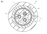
- FIG. 2 is a cross-sectional view along line 2-2 in FIG.
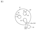
- FIG. 3 is a plan view of the sealing member in the same form.
- FIG. 4 is a cross-sectional view of a wire harness of a modification.
- FIG. 5 is a plan view of a sealing member in the modified example.
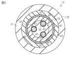
- FIG. 6 is a cross-sectional view of a wire harness of a modification.
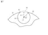
- FIG. 7 is a plan view showing a partially enlarged sealing member in the modification.
- FIG. 8 is a side view of a sealing member in a modified example.
- the wire harness of the present disclosure includes: [1] A grommet having a tubular portion, an electric wire passing through the tubular portion, and a columnar sealing member provided in the tubular portion, wherein the sealing member is one end in the axial direction. a first end, a second end that is the other end in the axial direction, and an insertion hole passing through the sealing member from the first end to the second end, the insertion hole
- the wire is inserted through the sealing member, and an opening is formed in the outer peripheral surface of the sealing member so that the insertion hole can be opened from the outer peripheral surface, and the opening extends from the first end to the It extends to the second end.
- the opening is a first slit cut from the outer peripheral surface of the sealing member to the insertion hole, and the first slit has a pair of inner surfaces facing each other,
- the member is deformable so as to widen the gap between the pair of inner surfaces, and by widening the gap between the pair of inner surfaces, the insertion hole can be opened from the outer peripheral surface of the sealing member.
- the pair of inner surfaces are in contact with each other in a state in which the electric wire is arranged in the insertion hole and the sealing member is arranged in the cylindrical portion. According to this configuration, since the pair of inner surfaces of the first slit are in contact with each other, it is possible to prevent water from entering between the pair of inner surfaces.
- the sealing member has a second slit cut from the insertion hole to a position inside the outer peripheral surface of the sealing member. According to this configuration, by providing the second slit, it becomes easier to deform the sealing member so as to increase the distance between the pair of inner surfaces. Therefore, it is possible to improve workability when attaching the electric wire to the sealing member from the first slit.
- the opening is a part of the insertion hole exposed on the outer peripheral surface of the sealing member. According to this configuration, it is possible to set the position of the outer peripheral surface of the sealing member at a reduced position so as to overlap with the insertion hole. Therefore, it is possible to contribute to miniaturization of the sealing member in the radial direction.
- the wire harness includes an elastic sheet provided on the outer peripheral surface of the sealing member so as to close the opening. According to this configuration, a part of the electric wire arranged in the insertion hole protrudes from the opening to the outer peripheral side of the sealing member, but the projection of the electric wire can be absorbed by the elasticity of the elastic sheet. . As a result, it is possible to suppress the occurrence of a gap around the sealing member even in a configuration in which a part of the electric wire protrudes from the outer peripheral surface of the sealing member. As a result, it becomes possible to suppress the deterioration of the water stopping performance inside the tubular portion of the grommet.
- a plurality of the electric wires, the insertion holes, and the openings are provided, and the elastic sheet is wound around the outer peripheral surface of the sealing member for at least one turn. According to this configuration, each opening formed in the outer peripheral surface of the sealing member is closed by the elastic sheet. Therefore, in a structure having a plurality of openings on the outer peripheral surface of the sealing member, it is possible to suitably suppress the occurrence of gaps around the sealing member.
- the wire harness 10 of the present embodiment includes a grommet 20 having a tubular portion 21, an electric wire 30 passing through the tubular portion 21, and a columnar sealing member provided inside the tubular portion 21. 40 and .
- Grommet 20 is made of a flexible material.
- EPDM specifically, ethylene propylene diene rubber
- the grommet 20 integrally has a tubular portion 21 and a seal portion 22 .
- the seal portion 22 is attached, for example, to a through hole Pa provided in a body panel P of the vehicle.
- the ring-shaped seal portion 22 is in close contact with the periphery of the through hole Pa. Thereby, the seal portion 22 suppresses the intrusion of water into the through hole Pa.
- the tubular portion 21 extends from the seal portion 22 .
- the electric wire 30 is passed through the cylindrical portion 21 and the seal portion 22 . Also, the electric wire 30 is passed through the through hole Pa of the body panel P. As shown in FIG. The electric wire 30 electrically connects devices (not shown) mounted on the vehicle.
- the electric wire 30 has a core wire 31 and an insulating coating 32 .
- the core wire 31 has conductivity.
- a stranded wire formed by twisting a plurality of metal wires, a single core wire formed of a single conductor, or the like can be used.
- a single-core wire for example, a columnar conductor made of a single columnar metal rod having a solid inner structure, a tubular conductor having a hollow inner structure, or the like can be used.
- a material for forming the core wire 31 for example, a metal material such as a copper-based material or an aluminum-based material can be used.
- the insulating coating 32 surrounds the outer circumference of the core wire 31 .
- the insulating coating 32 has electrical insulation.
- the insulating coating 32 covers, for example, the entire circumference of the outer peripheral surface of the core wire 31 .
- the insulating coating 32 is made of, for example, an insulating resin material.
- the wire harness 10 includes, for example, an electromagnetic shielding member 50 that collectively surrounds a plurality of electric wires 30 .
- the electromagnetic shield member 50 has a tubular shape. A plurality of electric wires 30 pass through the inside of the electromagnetic shield member 50 .
- the electromagnetic shield member 50 is passed through the tubular portion 21 and the seal portion 22 .
- the electromagnetic shield member 50 has conductivity.
- a braided wire in which a plurality of metal wires are knitted, a metal foil, or the like can be used.
- a material for forming the electromagnetic shield member 50 for example, a metal material such as a copper-based material or an aluminum-based material can be used.
- the sealing member 40 is for suppressing the flow of water in the tubular portion 21 .
- the sealing member 40 is made of, for example, a rubber material having elasticity.
- Materials for forming the sealing member 40 include silicone rubber, urethane rubber, acrylic rubber, nitrile rubber, butyl rubber, ethylene propylene rubber, and the like.
- the sealing member 40 has, for example, a substantially columnar shape.
- the sealing member 40 has a first end 41 that is one end in the axial direction and a second end 42 that is the other end in the axial direction. Further, the sealing member 40 has an insertion hole 43 penetrating through the sealing member 40 from the first end portion 41 to the second end portion 42 .
- the insertion hole 43 is formed along the axial direction of the sealing member 40 .
- a plurality of insertion holes 43 are provided corresponding to the plurality of electric wires 30 respectively. That is, in this embodiment, three insertion holes 43 are provided. An electric wire 30 is inserted through each insertion hole 43 . The inner peripheral surface of the insertion hole 43 is in close contact with the outer peripheral surface of the insulating coating 32 . The cross-sectional shape of the insertion hole 43 follows the cross-sectional shape of the electric wire 30 .
- the electric wire 30 and the insertion hole 43 of this embodiment have a circular cross-sectional shape, for example.
- the insertion holes 43 are, for example, arranged at equal angular intervals on the same circle centered on the central axis L1 of the sealing member 40 .
- a slit 44 is formed in the outer peripheral surface of the sealing member 40 as an opening through which the insertion hole 43 can be opened from the outer peripheral surface. As shown in FIG. 1, slit 44 extends from first end 41 to second end 42 of sealing member 40 . As shown in FIG. 2, a plurality of slits 44 are provided corresponding to the plurality of insertion holes 43, respectively. That is, three slits 44 are provided in this embodiment. The slit 44 is cut from the outer peripheral surface of the sealing member 40 to the insertion hole 43 .
- the slit 44 is formed, for example, along a straight line S1 perpendicular to the central axis L1 of the sealing member 40 and the central axis L2 of the insertion hole 43 .
- the straight line S1 is a straight line orthogonal to the center axis L1 of the sealing member 40 and the tangent line Q of the cross-sectional circle of the sealing member 40 .
- the slit 44 is formed linearly along the axial direction of the sealing member 40, for example.
- the slit 44 has a pair of inner surfaces 44a facing each other.
- the pair of inner surfaces 44a are surfaces of cut ends of the slits 44 that are cut.
- the sealing member 40 is deformable so that the gap between the pair of inner surfaces 44a of the slit 44 is widened.
- the insertion hole 43 can be opened from the outer peripheral surface of the sealing member 40 . This allows the wire 30 to be fitted into the insertion hole 43 through the slit 44 from the outer peripheral side of the sealing member 40 .
- FIG. 2 when the wire 30 is arranged in the insertion hole 43 and the sealing member 40 is arranged in the cylindrical portion 21, the pair of inner surfaces 44a of the slit 44 are in contact with each other.
- the wire harness 10 includes, for example, an outer peripheral sheet 60 interposed between the outer peripheral surface of the sealing member 40 and the inner peripheral surface of the tubular portion 21 .
- the peripheral sheet 60 has elasticity.
- Materials for forming the outer peripheral sheet 60 include, for example, butyl rubber, urethane rubber, silicone rubber, acrylic rubber, nitrile rubber, and ethylene propylene rubber.
- the outer peripheral sheet 60 is attached by being wound around the outer peripheral surface of the sealing member 40 from above the electromagnetic shield member 50 for one or more turns.
- the outer peripheral sheet 60 is fixed to the outer peripheral surface of the electromagnetic shield member 50 that covers the outer peripheral side of the sealing member 40 by, for example, an adhesive layer provided on one surface thereof.
- the outer peripheral sheet 60 is interposed between the outer peripheral surface of the sealing member 40 and the inner peripheral surface of the tubular portion 21 in a compressed state.
- the outer peripheral surface of the outer peripheral sheet 60 is in close contact with the inner peripheral surface of the tubular portion 21 . That is, the outer peripheral sheet 60 fills the gap between the electromagnetic shield member 50 and the cylindrical portion 21 .
- the ease with which the sealing member 40 is attached to the electric wire 30 does not change depending on the attachment position of the sealing member 40 to the electric wire 30 . That is, when the mounting position of the sealing member 40 is near the center in the length direction of the electric wire 30, when the electric wire 30 is inserted into the insertion hole 43 from the first end 41 or the second end 42 of the sealing member 40, It is necessary to move the sealing member 40 from the end of the wire 30 to near the center. In this respect, according to the configuration of the present embodiment, even if the mounting position of the sealing member 40 is near the center of the electric wire 30 , the sealing member 40 can be directly mounted near the center of the electric wire 30 . Therefore, it is possible to easily attach the sealing member 40 to the electric wire 30 .
- the slit 44 is cut from the outer peripheral surface of the sealing member 40 to the insertion hole 43 .
- the slit 44 has a pair of inner surfaces 44a facing each other.
- the sealing member 40 can be deformed so as to increase the distance between the pair of inner surfaces 44a.
- the insertion hole 43 can be opened from the outer peripheral surface of the sealing member 40 . According to this configuration, it is possible to open the insertion hole 43 from the outer peripheral surface of the sealing member 40 by opening the slit 44 . Therefore, the electric wire 30 can be fitted into the insertion hole 43 through the slit 44 .
- the pair of inner surfaces 44a are in contact with each other when the electric wire 30 is arranged in the insertion hole 43 and the sealing member 40 is arranged in the tubular portion 21 . According to this configuration, since the pair of inner surfaces 44a of the slit 44 are in contact with each other, it is possible to prevent water from entering between the pair of inner surfaces 44a.
- the sealing member 40 has only one slit 44 connected to one insertion hole 43 . Therefore, since the number of slits 44 can be reduced, it is possible to suitably suppress the deterioration of the water stopping performance of the sealing member 40 .
- the configuration of the slits of the sealing member 40 may be changed to the configurations shown in FIGS. 4 and 5, for example.
- the outer peripheral surface of the sealing member 40 is formed with a first slit 71 as an opening through which the insertion hole 43 can be opened.
- the first slit 71 extends axially from the first end 41 to the second end 42 .
- a plurality of first slits 71 are provided corresponding to the plurality of insertion holes 43 respectively.
- the first slit 71 is cut from the outer peripheral surface of the sealing member 40 to the insertion hole 43 .
- the first slit 71 has a pair of inner surfaces 71a facing each other.
- the pair of inner surfaces 71a are surfaces of cut ends of the first slit 71 that is cut.
- the outer peripheral edge of the first slit 71 that is, the position where the first slit 71 connects to the outer peripheral surface of the sealing member 40, is the opening angle ⁇ of the insertion hole 43 centered on the central axis L1. is set within the range of The opening angle .theta. The range is up to S3.
- the sealing member 40 has a second slit 72 cut from the insertion hole 43 to a position inside the outer peripheral surface of the sealing member 40 .
- the second slit 72 extends axially from the first end 41 to the second end 42 .
- a plurality of second slits 72 are provided corresponding to the plurality of insertion holes 43 respectively.
- the inner peripheral side end of the second slit 72 is connected to the insertion hole 43 .
- the outer peripheral side end of the second slit 72 is located on the inner diameter side of the outer peripheral surface of the sealing member 40 .
- the position of the outer peripheral side edge of the second slit 72 is provided outside the range of the opening angle ⁇ of the insertion hole 43 . This makes it possible to secure the length of the second slit 72 .
- a portion of the sealing member 40 surrounded by the first slit 71 and the second slit 72 connected to the same insertion hole 43 and the outer peripheral surface of the sealing member 40 functions as a lid portion 73 .
- a portion between the outer peripheral side end of the second slit 72 and the outer peripheral surface of the sealing member 40 functions as a hinge portion 74 .
- opening the second slit 72 facilitates deforming the sealing member 40 so that the distance between the pair of inner surfaces 71a of the first slit 71 increases. Therefore, it is possible to improve workability when attaching the electric wire 30 to the sealing member 40 from the first slit 71 .
- the configuration of the slits of the sealing member 40 may be changed to the configurations shown in FIGS. 6 and 7, for example.
- the outer peripheral surface of the sealing member 40 is formed with an opening 81 through which the insertion hole 43 can be opened.
- the opening 81 extends axially from the first end 41 to the second end 42 .
- a plurality of openings 81 are provided corresponding to the plurality of insertion holes 43 respectively.
- the opening 81 is part of the insertion hole 43 exposed on the outer peripheral surface of the sealing member 40 . That is, in the insertion hole 43 of this configuration, the distance D1 from the center axis L2 to the outer peripheral surface of the sealing member 40 is set smaller than the radius D2 of the insertion hole 43 . In other words, the insertion hole 43 has a shape in which a part of the peripheral edge is missing when viewed from the axial direction of the sealing member 40 . The opening 81 is open even when the sealing member 40 is arranged inside the tubular portion 21 .
- the electric wire 30 is fitted into the insertion hole 43 through the opening 81 from the outer peripheral side of the sealing member 40 .
- a portion of the electric wire 30 assembled in the insertion hole 43 protrudes radially outward of the sealing member 40 from the opening 81 .
- the elastic sheet 82 has elasticity.
- Materials for forming the elastic sheet 82 include, for example, butyl rubber, urethane rubber, silicone rubber, acrylic rubber, nitrile rubber, and ethylene propylene rubber.
- the elastic sheet 82 is attached to the sealing member 40 with the electric wires 30 attached to the respective insertion holes 43 by being wound around the outer peripheral surface of the sealing member 40 one or more times.
- the elastic sheet 82 is fixed to the outer peripheral surface of the sealing member 40 and a portion of the electric wire 30 protruding from the opening 81 by, for example, an adhesive layer provided on one side surface of the elastic sheet 82 .
- the elastic sheet 82 is arranged on the inner peripheral side of the electromagnetic shield member 50 . That is, the electromagnetic shield member 50 is sandwiched between the elastic sheet 82 and the peripheral sheet 60 . The elastic sheet 82 is interposed between the sealing member 40 and the electromagnetic shield member 50 in a compressed state.
- the opening 81 is a part of the insertion hole 43 exposed on the outer peripheral surface of the sealing member 40, the position of the outer peripheral surface of the sealing member 40 is inserted. It can be set at a reduced position so as to overlap with the hole 43 . Therefore, it is possible to contribute to miniaturization of the sealing member 40 in the radial direction.
- a part of the electric wire 30 arranged in the insertion hole 43 protrudes from the opening 81 to the outer peripheral side of the sealing member 40 , but the projection of the electric wire 30 is caused by the elastic force of the elastic sheet 82 .
- can be absorbed by This makes it possible to suppress the occurrence of gaps around the sealing member 40 even when a part of the electric wire 30 protrudes from the outer peripheral surface of the sealing member 40 .
- the elastic sheet 82 is wound around the outer peripheral surface of the sealing member 40 for at least one turn. Therefore, each opening 81 formed on the outer peripheral surface of the sealing member 40 is closed by the elastic sheet 82 . Therefore, in a configuration having a plurality of openings 81 on the outer peripheral surface of sealing member 40 , it is possible to suitably suppress the occurrence of gaps around sealing member 40 .
- the slit 44 in the above embodiment is formed linearly along the axial direction of the sealing member 40, but is not particularly limited to this.
- the slit 44 may have a bent portion 45 at an intermediate portion in the axial direction of the sealing member 40 .
- the slit 44 is displaced in the circumferential direction of the sealing member 40 at the bent portion 45 .
- the bent portion 45 can improve the waterproof performance of the sealing member 40 .
- a similar effect can be obtained by forming the bent portion 45 in the first slit 71 having the configuration shown in FIGS.
- each electric wire 30 of the said embodiment into a shield electric wire.
- the electromagnetic shield member 50 can be omitted.
- the number of electric wires 30 passing through the sealing member 40 is not limited to the above embodiment, and can be appropriately changed to one, two, or four or more depending on the configuration.
- the pair of inner surfaces 44a of the slit 44 may be in contact with each other, and the contour of the inward surface of the insertion hole 43 extends radially. It may be circular with no openings.
- the contour of the inward surface of the insertion hole 43 corresponds to the diameter. It may have an elliptical arc shape with an opening in the direction. The width of the opening in the circumferential direction of the sealing member 40 may change as the distance between the pair of inner surfaces 44a of the slit 44 changes.
- the pair of inner surfaces 71a of the first slit 71 may be in contact with each other, and the pair of inner surfaces of the second slit 72 may be in contact with each other.
- the inward surface of the insertion hole 43 may have a circular shape with no opening in the radial direction.
- the first slit 71 has a gap between the pair of inner surfaces 71 a larger than the gap between the pair of inner surfaces of the second slit 72 .
- the interval between the pair of inner surfaces 71a of the slit 71 and the interval between the pair of inner surfaces of the second slit 72 may be increased.
- the inward surface of the insertion hole 43 may have an arcuate shape with an opening in the radial direction.
- the width of the opening in the circumferential direction of the sealing member 40 may be smaller than the outer diameter of the wire 30, and the distance between the pair of inner surfaces 71a of the first slit 71 and the distance between the pair of inner surfaces of the second slit 72 does not have to change with changes in
- the outer peripheral surface of the sealing member 40 may have a plurality of curved outward surfaces separated from each other along the circumferential direction by a plurality of insertion holes 43 .
- the outer peripheral surface of the sealing member 40 may have three curved outwardly facing surfaces which are separated and segmented from each other along the circumferential direction by means of the three insertion holes 43 .
- the contour of the inward surface of the insertion hole 43 viewed from the axial direction of the sealing member 40 may be arcuate with an opening 81 in the radial direction.
- the width of opening 81 in the circumferential direction of sealing member 40 may be smaller than the outer diameter of electric wire 30 .
Landscapes
- Engineering & Computer Science (AREA)
- Architecture (AREA)
- Civil Engineering (AREA)
- Structural Engineering (AREA)
- Insulating Bodies (AREA)
- Installation Of Indoor Wiring (AREA)
- Insulated Conductors (AREA)
Abstract
本開示の一態様は、組立作業性の向上を図ることができるワイヤハーネスを提供する。本開示の一態様に従うワイヤハーネス(10)は、筒部(21)を有するグロメット(20)と、筒部(21)内に通されている電線(30)と、筒部(21)内に設けられる柱状の封止部材(40)と、を備えている。封止部材(40)は、軸方向の一端部である第1端部と、軸方向の他端部である第2端部と、第1端部から第2端部まで封止部材(40)を貫通する挿通孔(43)と、を有している。挿通孔(43)には、電線(30)が挿通されている。封止部材(40)の外周面には、当該外周面から挿通孔(43)を開口可能な開口部としてのスリット(44)が形成されている。スリット(44)は、第1端部から第2端部まで延びている。
Description
本開示は、ワイヤハーネスに関するものである。
例えば、特許文献1に記載のワイヤハーネスは、筒部を有するグロメットと、筒部内に通されている電線と、筒部内に設けられる封止部材とを備えている。封止部材は、弾性を有する柱状体である。封止部材は、封止部材の軸方向一端部から他端部まで貫通する挿通孔を有している。封止部材の挿通孔には、電線が挿通されている。封止部材は、グロメットの筒部への水の浸入を抑制している。
電線端部に端子を装着するなどの端末処理が必要な場合、電線を封止部材の挿通孔に通す前に端末処理を行うと、電線端部が挿通孔に入らなくなるおそれがある。したがって、端末処理の前に電線を封止部材の挿通孔に通す必要があった。このように、上記のようなワイヤハーネスでは、組立作業の工程順に制約があった。
本開示の目的は、組立作業性の向上を図ることができるワイヤハーネスを提供することにある。
本開示のワイヤハーネスは、筒部を有するグロメットと、前記筒部内に通されている電線と、前記筒部内に設けられる柱状の封止部材と、を備え、前記封止部材は、軸方向の一端部である第1端部と、軸方向の他端部である第2端部と、前記第1端部から前記第2端部まで前記封止部材を貫通する挿通孔と、を有し、前記挿通孔には、前記電線が挿通され、前記封止部材の外周面には、当該外周面から前記挿通孔を開口可能な開口部が形成されており、前記開口部は、前記第1端部から前記第2端部まで延びている。
本開示のワイヤハーネスは、組立作業性を向上させる効果を発揮する。
[本開示の実施形態の説明]
最初に本開示の実施態様を列記して説明する。
本開示のワイヤハーネスは、
[1]筒部を有するグロメットと、前記筒部内に通されている電線と、前記筒部内に設けられる柱状の封止部材と、を備え、前記封止部材は、軸方向の一端部である第1端部と、軸方向の他端部である第2端部と、前記第1端部から前記第2端部まで前記封止部材を貫通する挿通孔と、を有し、前記挿通孔には、前記電線が挿通され、前記封止部材の外周面には、当該外周面から前記挿通孔を開口可能な開口部が形成されており、前記開口部は、前記第1端部から前記第2端部まで延びている。
最初に本開示の実施態様を列記して説明する。
本開示のワイヤハーネスは、
[1]筒部を有するグロメットと、前記筒部内に通されている電線と、前記筒部内に設けられる柱状の封止部材と、を備え、前記封止部材は、軸方向の一端部である第1端部と、軸方向の他端部である第2端部と、前記第1端部から前記第2端部まで前記封止部材を貫通する挿通孔と、を有し、前記挿通孔には、前記電線が挿通され、前記封止部材の外周面には、当該外周面から前記挿通孔を開口可能な開口部が形成されており、前記開口部は、前記第1端部から前記第2端部まで延びている。
この構成によれば、封止部材の外周面に形成された開口部から挿通孔に電線を嵌め込むことが可能となる。このため、挿通孔に対して第1端部側または第2端部側の端部から電線を通す作業が不要となる。これにより、端末処理を行った後の電線に封止部材を取り付けることが可能となる。したがって、ワイヤハーネスの組立作業における工程順の制約が緩和され、その結果、組立作業性の向上を図ることができる。
[2]前記開口部は、前記封止部材の外周面から前記挿通孔にまで切り込まれた第1スリットであり、前記第1スリットは、互いに対向する一対の内面を有し、前記封止部材は、前記一対の内面間の間隔が拡がるように変形可能であり、前記一対の内面間の間隔が拡がることにより、前記封止部材の外周面から前記挿通孔を開口可能である。
この構成によれば、開口部としての第1スリットを開くことで、封止部材の外周面から挿通孔を開口することが可能である。このため、第1スリットを通じて電線を挿通孔に嵌め込むことが可能となる。
[3]前記電線が前記挿通孔内に配置され、かつ、前記封止部材が前記筒部内に配置された状態において、前記一対の内面が互いに接している。
この構成によれば、第1スリットの一対の内面が互いに接するため、一対の内面の間に水が浸入することを抑制できる。
この構成によれば、第1スリットの一対の内面が互いに接するため、一対の内面の間に水が浸入することを抑制できる。
[4]前記封止部材は、前記挿通孔から前記封止部材の外周面よりも内側の位置まで切り込まれた第2スリットを有している。
この構成によれば、第2スリットを設けることで、一対の内面間の間隔が拡がるように封止部材を変形させやすくなる。したがって、電線を第1スリットから封止部材に取り付ける際の作業性を向上させることが可能となる。
この構成によれば、第2スリットを設けることで、一対の内面間の間隔が拡がるように封止部材を変形させやすくなる。したがって、電線を第1スリットから封止部材に取り付ける際の作業性を向上させることが可能となる。
[5]前記開口部は、前記封止部材の外周面上に露出した前記挿通孔の一部である。
この構成によれば、封止部材の外周面の位置を挿通孔と重なるように縮小した位置に設定可能となる。したがって、封止部材の径方向の小型化に寄与できる。
この構成によれば、封止部材の外周面の位置を挿通孔と重なるように縮小した位置に設定可能となる。したがって、封止部材の径方向の小型化に寄与できる。
[6]前記ワイヤハーネスは、前記封止部材の外周面において前記開口部を塞ぐように設けられた弾性シートを備えている。
この構成によれば、挿通孔内に配置された電線の一部が、開口部から封止部材の外周側に突出するが、その電線の突出を弾性シートの弾性によって吸収することが可能となる。これにより、電線の一部が封止部材の外周面から突出する構成であっても、封止部材の周囲における隙間の発生を抑制することが可能となる。その結果、グロメットの筒部の内側における止水性能の低下を抑制可能となる。
この構成によれば、挿通孔内に配置された電線の一部が、開口部から封止部材の外周側に突出するが、その電線の突出を弾性シートの弾性によって吸収することが可能となる。これにより、電線の一部が封止部材の外周面から突出する構成であっても、封止部材の周囲における隙間の発生を抑制することが可能となる。その結果、グロメットの筒部の内側における止水性能の低下を抑制可能となる。
[7]前記電線、前記挿通孔及び前記開口部は、複数設けられ、前記弾性シートは、前記封止部材の外周面に少なくとも1周以上巻き付けられている。
この構成によれば、封止部材の外周面に形成された各開口部を弾性シートが塞ぐ構成となる。したがって、封止部材の外周面に複数の開口部を有する構成において、封止部材の周囲における隙間の発生を好適に抑制することが可能となる。
この構成によれば、封止部材の外周面に形成された各開口部を弾性シートが塞ぐ構成となる。したがって、封止部材の外周面に複数の開口部を有する構成において、封止部材の周囲における隙間の発生を好適に抑制することが可能となる。
[本開示の実施形態の詳細]
本開示のワイヤハーネスの具体例を、以下に図面を参照しつつ説明する。各図面では、説明の便宜上、構成の一部を誇張または簡略化して示す場合がある。また、各部分の寸法比率については各図面で異なる場合がある。また、本明細書における「直交」は、厳密に直交の場合のみでなく、本実施形態における作用ならびに効果を奏する範囲内で概ね直交の場合も含まれる。
本開示のワイヤハーネスの具体例を、以下に図面を参照しつつ説明する。各図面では、説明の便宜上、構成の一部を誇張または簡略化して示す場合がある。また、各部分の寸法比率については各図面で異なる場合がある。また、本明細書における「直交」は、厳密に直交の場合のみでなく、本実施形態における作用ならびに効果を奏する範囲内で概ね直交の場合も含まれる。
図1に示すように、本実施形態のワイヤハーネス10は、筒部21を有するグロメット20と、筒部21内に通されている電線30と、筒部21内に設けられる柱状の封止部材40と、を備えている。
(グロメット20の構成)
グロメット20は、柔軟性のある材料によって形成されている。グロメット20の形成材料としては、例えば、EPDM(詳しくは、エチレンプロピレンジエンゴム)などを用いることができる。
グロメット20は、柔軟性のある材料によって形成されている。グロメット20の形成材料としては、例えば、EPDM(詳しくは、エチレンプロピレンジエンゴム)などを用いることができる。
グロメット20は、筒部21とシール部22とを一体に有している。シール部22は、例えば、車両のボディパネルPに設けられた貫通孔Paに取り付けられる。環状をなすシール部22は、貫通孔Paの周縁に密着する。これにより、シール部22は、貫通孔Paへの水の浸入を抑制する。筒部21は、シール部22から延出している。
(電線30の構成)
電線30は、筒部21とシール部22とに通されている。また、電線30は、ボディパネルPの貫通孔Paに通されている。電線30は、車両に搭載された図示しない機器同士を電気的に接続する。
電線30は、筒部21とシール部22とに通されている。また、電線30は、ボディパネルPの貫通孔Paに通されている。電線30は、車両に搭載された図示しない機器同士を電気的に接続する。
図2に示すように、電線30は、例えば3本設けられている。電線30は、芯線31と、絶縁被覆32とを有している。芯線31は、導電性を有する。芯線31としては、例えば、複数の金属素線を撚り合わせてなる撚線や、単一の導体からなる単芯線などを用いることができる。単芯線としては、例えば、内部が中実構造をなす柱状の1本の金属棒からなる柱状導体や内部が中空構造をなす筒状導体などを用いることができる。芯線31の形成材料としては、例えば、銅系やアルミニウム系などの金属材料を用いることができる。
絶縁被覆32は、芯線31の外周を囲っている。絶縁被覆32は、電気的な絶縁性を有する。絶縁被覆32は、例えば、芯線31の外周面を周方向全周にわたって被覆している。絶縁被覆32は、例えば、絶縁性を有する樹脂材料により構成されている。
(電磁シールド部材50の構成)
図1及び図2に示すように、ワイヤハーネス10は、例えば、複数の電線30をまとめて包囲する電磁シールド部材50を備える。電磁シールド部材50は、筒状をなしている。複数の電線30は、電磁シールド部材50の内側を通っている。電磁シールド部材50は、筒部21とシール部22とに通されている。
図1及び図2に示すように、ワイヤハーネス10は、例えば、複数の電線30をまとめて包囲する電磁シールド部材50を備える。電磁シールド部材50は、筒状をなしている。複数の電線30は、電磁シールド部材50の内側を通っている。電磁シールド部材50は、筒部21とシール部22とに通されている。
電磁シールド部材50は導電性を有している。電磁シールド部材50としては、例えば、複数の金属素線が編成された編組線や、金属箔などを用いることができる。電磁シールド部材50の形成材料としては、例えば、銅系やアルミニウム系などの金属材料を用いることができる。
(封止部材40の構成)
封止部材40は、筒部21における水の流通を抑制するためのものである。封止部材40は、弾性を有する例えばゴム材料にて形成されている。封止部材40の形成材料としては、シリコーンゴム、ウレタンゴム、アクリルゴム、ニトリルゴム、ブチルゴム、エチレンプロピレンゴムなどが挙げられる。
封止部材40は、筒部21における水の流通を抑制するためのものである。封止部材40は、弾性を有する例えばゴム材料にて形成されている。封止部材40の形成材料としては、シリコーンゴム、ウレタンゴム、アクリルゴム、ニトリルゴム、ブチルゴム、エチレンプロピレンゴムなどが挙げられる。
封止部材40は、例えば、略円柱状をなしている。封止部材40は、軸方向の一端部である第1端部41と、軸方向の他端部である第2端部42とを有している。また、封止部材40は、第1端部41から第2端部42まで封止部材40を貫通する挿通孔43を有している。挿通孔43は、封止部材40の軸方向に沿って形成されている。
図2に示すように、挿通孔43は、複数の電線30にそれぞれ対応して複数設けられている。つまり、本実施形態では、挿通孔43が3つ設けられている。各挿通孔43には、電線30が挿通されている。挿通孔43の内周面は、絶縁被覆32の外周面に密着している。挿通孔43の断面形状は、電線30の断面形状に倣った形状をなす。本実施形態の電線30及び挿通孔43の断面形状は、例えば円形をなしている。各挿通孔43は、例えば、封止部材40の中心軸線L1を中心とする同一円上に、等角度間隔を置いて配置されている。
封止部材40の外周面には、当該外周面から挿通孔43を開口可能な開口部としてのスリット44が形成されている。図1に示すように、スリット44は、封止部材40の第1端部41から第2端部42まで延びている。図2に示すように、スリット44は、複数の挿通孔43にそれぞれ対応して複数設けられている。つまり、本実施形態では、スリット44が3つ設けられている。スリット44は、封止部材40の外周面から挿通孔43にまで切り込まれている。スリット44は、例えば、封止部材40の中心軸線L1及び挿通孔43の中心軸線L2に直交する直線S1に沿って形成されている。直線S1は、封止部材40の中心軸線L1及び封止部材40の断面円の接線Qに直交する直線である。また、スリット44は、例えば、封止部材40の軸方向に沿って直線状に形成されている。
図3に示すように、スリット44は、互いに対向する一対の内面44aを有している。一対の内面44aは、切り込まれたスリット44の切り口の面である。封止部材40は、スリット44の一対の内面44a間の間隔が拡がるように変形可能である。そして、一対の内面44a間の間隔が拡がることにより、封止部材40の外周面から挿通孔43を開口可能である。これにより、封止部材40の外周側からスリット44を通じて電線30を挿通孔43に嵌め込むことが可能となっている。また、図2に示すように、電線30が挿通孔43内に配置され、かつ、封止部材40が筒部21内に配置された状態において、スリット44の一対の内面44aは、互いに接している。
(外周シート60の構成)
図1及び図2に示すように、ワイヤハーネス10は、例えば、封止部材40の外周面と筒部21の内周面との間に介在される外周シート60を備える。外周シート60は、弾性を有している。外周シート60の形成材料としては、例えば、ブチルゴム、ウレタンゴム、シリコーンゴム、アクリルゴム、ニトリルゴム、エチレンプロピレンゴムなど挙げられる。
図1及び図2に示すように、ワイヤハーネス10は、例えば、封止部材40の外周面と筒部21の内周面との間に介在される外周シート60を備える。外周シート60は、弾性を有している。外周シート60の形成材料としては、例えば、ブチルゴム、ウレタンゴム、シリコーンゴム、アクリルゴム、ニトリルゴム、エチレンプロピレンゴムなど挙げられる。
外周シート60は、例えば、電磁シールド部材50の上から封止部材40の外周面に1周以上巻かれて取り付けられている。外周シート60は、例えば、その一方の面に設けられた粘着層によって、封止部材40の外周側を覆う電磁シールド部材50の外周面に固定される。外周シート60は、封止部材40の外周面と筒部21の内周面との間に圧縮状態で介在される。外周シート60の外周面は、筒部21の内周面に密着している。すなわち、外周シート60によって、電磁シールド部材50と筒部21との間の隙間が埋められる。
本実施形態の作用について説明する。
封止部材40の外周側からスリット44を通じて電線30を挿通孔43に嵌め込むことが可能である。これにより、電線30の長さ方向の端部において図示しない端子を芯線31に固定するなどの端末処理を行った後でも、電線30に封止部材40を取り付けることが可能である。
封止部材40の外周側からスリット44を通じて電線30を挿通孔43に嵌め込むことが可能である。これにより、電線30の長さ方向の端部において図示しない端子を芯線31に固定するなどの端末処理を行った後でも、電線30に封止部材40を取り付けることが可能である。
また、本実施形態の構成では、電線30に対する封止部材40の取り付けの容易さは、電線30に対する封止部材40の取り付け位置によって変わらない。すなわち、封止部材40の取り付け位置が電線30の長さ方向の中央付近である場合、電線30を封止部材40の第1端部41または第2端部42から挿通孔43に挿入すると、封止部材40を電線30の端部から中央付近まで移動させる必要がある。その点、本実施形態の構成によれば、封止部材40の取り付け位置が電線30の中央付近であっても、封止部材40を電線30の中央付近に直接取り付けることができる。よって、電線30に封止部材40を容易に取り付けることが可能である。
本実施形態の効果について説明する。
(1)封止部材40の外周面に形成された開口部としてのスリット44から挿通孔43に電線30を嵌め込むことが可能となる。このため、挿通孔43に対して第1端部41側または第2端部42側の端部から電線30を通す作業が不要となる。これにより、端末処理を行った後の電線30に封止部材40を取り付けることが可能となる。したがって、ワイヤハーネス10の組立作業における工程順の制約が緩和され、その結果、組立作業性の向上を図ることができる。
(1)封止部材40の外周面に形成された開口部としてのスリット44から挿通孔43に電線30を嵌め込むことが可能となる。このため、挿通孔43に対して第1端部41側または第2端部42側の端部から電線30を通す作業が不要となる。これにより、端末処理を行った後の電線30に封止部材40を取り付けることが可能となる。したがって、ワイヤハーネス10の組立作業における工程順の制約が緩和され、その結果、組立作業性の向上を図ることができる。
(2)スリット44は、封止部材40の外周面から挿通孔43にまで切り込まれている。スリット44は、互いに対向する一対の内面44aを有している。封止部材40は、一対の内面44a間の間隔が拡がるように変形可能である。そして、一対の内面44a間の間隔が拡がることにより、封止部材40の外周面から挿通孔43を開口可能である。この構成によれば、スリット44を開くことで、封止部材40の外周面から挿通孔43を開口することが可能である。このため、スリット44を通じて電線30を挿通孔43に嵌め込むことが可能となる。
(3)電線30が挿通孔43内に配置され、かつ、封止部材40が筒部21内に配置された状態において、一対の内面44aが互いに接している。この構成によれば、スリット44の一対の内面44aが互いに接するため、一対の内面44aの間に水が浸入することを抑制できる。
(4)封止部材40において、1つの挿通孔43に繋がるスリット44が1つのみである。したがって、スリット44の数を少なく抑えられるため、封止部材40の止水性能の低下を好適に抑制することが可能となる。
<変更例>
本実施形態は、以下のように変更して実施することができる。本実施形態及び以下の変更例は、技術的に矛盾しない範囲で互いに組み合わせて実施することができる。
本実施形態は、以下のように変更して実施することができる。本実施形態及び以下の変更例は、技術的に矛盾しない範囲で互いに組み合わせて実施することができる。
・封止部材40のスリットの構成を例えば図4及び図5に示す構成に変更してもよい。図4及び図5に示すように、封止部材40の外周面には、当該外周面から挿通孔43を開口可能な開口部としての第1スリット71が形成されている。第1スリット71は、第1端部41から第2端部42まで軸方向に沿って延びている。第1スリット71は、複数の挿通孔43にそれぞれ対応して複数設けられている。第1スリット71は、封止部材40の外周面から挿通孔43にまで切り込まれている。第1スリット71は、互いに対向する一対の内面71aを有している。一対の内面71aは、切り込まれた第1スリット71の切り口の面である。
図5に示すように、第1スリット71の外周側端部、すなわち、第1スリット71が封止部材40の外周面に繋がる位置は、中心軸線L1を中心とする挿通孔43の開角度θの範囲内に設けられている。挿通孔43の開角度θは、封止部材40の周方向において、中心軸線L1と挿通孔43の一端部とを通る直線S2から、中心軸線L1と挿通孔43の他端部とを通る直線S3までの範囲である。
封止部材40は、挿通孔43から封止部材40の外周面よりも内側の位置まで切り込まれた第2スリット72を有している。第2スリット72は、第1端部41から第2端部42まで軸方向に沿って延びている。第2スリット72は、複数の挿通孔43にそれぞれ対応して複数設けられている。
第2スリット72の内周側端部は、挿通孔43に繋がっている。第2スリット72の外周側端部は、封止部材40の外周面よりも内径側に位置している。第2スリット72の外周側端部の位置は、前記挿通孔43の開角度θの範囲外に設けられている。これにより、第2スリット72の長さを確保することが可能となる。
封止部材40において同一の挿通孔43に繋がる第1スリット71と第2スリット72と封止部材40の外周面とで囲まれた部位は、蓋部73として機能する。また、第2スリット72の外周側端部と封止部材40の外周面との間の部位は、ヒンジ部74として機能する。
蓋部73がヒンジ部74を支点として開方向に回動することで、第1スリット71の一対の内面71a間の間隔が拡がり、封止部材40の外周面から挿通孔43が開口される。これにより、封止部材40の外周側から第1スリット71を通じて電線30を挿通孔43に嵌め込むことが可能となっている。また、図4に示すように、電線30が挿通孔43内に配置され、かつ、封止部材40が筒部21内に配置された状態において、第1スリット71の一対の内面71aは、互いに接している。
図4及び図5に示すような構成によれば、第2スリット72が開くことによって、第1スリット71の一対の内面71a間の間隔が拡がるように封止部材40を変形させやすくなる。したがって、電線30を第1スリット71から封止部材40に取り付ける際の作業性を向上させることが可能となる。
・封止部材40のスリットの構成を例えば図6及び図7に示す構成に変更してもよい。図6及び図7に示すように、封止部材40の外周面には、当該外周面から挿通孔43を開口可能な開口部81が形成されている。開口部81は、第1端部41から第2端部42まで軸方向に沿って延びている。開口部81は、複数の挿通孔43にそれぞれ対応して複数設けられている。
開口部81は、封止部材40の外周面上に露出した挿通孔43の一部である。すなわち、本構成の挿通孔43は、中心軸線L2から封止部材40の外周面までの距離D1が挿通孔43の半径D2よりも小さく設定されている。換言すると、挿通孔43は、封止部材40の軸方向から見て、周縁の一部が欠けた形状をなしている。開口部81は、封止部材40が筒部21内に配置された状態においても開口している。
電線30は、封止部材40の外周側から開口部81を通じて挿通孔43に嵌め込まれる。挿通孔43に組み付けられた電線30の一部は、開口部81から封止部材40の径方向外側に突出している。
図6に示す構成のワイヤハーネス10は、封止部材40の外周面において開口部81を塞ぐように設けられた弾性シート82を備えている。弾性シート82は、弾性を有している。弾性シート82の形成材料としては、例えば、ブチルゴム、ウレタンゴム、シリコーンゴム、アクリルゴム、ニトリルゴム、エチレンプロピレンゴムなど挙げられる。弾性シート82は、電線30が各挿通孔43に組み付けられた状態の封止部材40に対して、封止部材40の外周面に1周以上巻かれて取り付けられている。弾性シート82は、例えば、その一側面に設けられた粘着層によって封止部材40の外周面及び開口部81から突出する電線30の一部に固定される。
弾性シート82は、電磁シールド部材50の内周側に配置される。すなわち、電磁シールド部材50は、弾性シート82と外周シート60とによって挟まれている。弾性シート82は、封止部材40と電磁シールド部材50との間に圧縮状態で介在されている。
図6及び図7に示すような構成によれば、開口部81が封止部材40の外周面上に露出した挿通孔43の一部であるため、封止部材40の外周面の位置を挿通孔43と重なるように縮小した位置に設定可能となる。したがって、封止部材40の径方向の小型化に寄与できる。
また、同構成によれば、挿通孔43内に配置された電線30の一部が、開口部81から封止部材40の外周側に突出するが、その電線30の突出を弾性シート82の弾性によって吸収することが可能となる。これにより、電線30の一部が封止部材40の外周面から突出する構成であっても、封止部材40の周囲における隙間の発生を抑制することが可能となる。その結果、グロメット20の筒部21の内側における止水性能の低下を抑制可能となる。
また、同構成によれば、弾性シート82は、封止部材40の外周面に少なくとも1周以上巻き付けられている。このため、封止部材40の外周面に形成された各開口部81を弾性シート82が塞ぐ構成となる。したがって、封止部材40の外周面に複数の開口部81を有する構成において、封止部材40の周囲における隙間の発生を好適に抑制することが可能となる。
・上記実施形態のスリット44は、封止部材40の軸方向に沿って直線状に形成されるが、これに特に限定されるものではない。例えば図8に示すように、封止部材40の軸方向の中間部において、スリット44が屈曲部45を有する構成としてもよい。スリット44は、屈曲部45において封止部材40の周方向に変位している。これにより、封止部材40の第1端部41側または第2端部42側からスリット44に水が浸入した場合に、スリット44を通る水の流れを屈曲部45にて抑制することが可能となる。したがって、屈曲部45によって封止部材40の止水性能を向上させることが可能となる。なお、図4及び図5に示す構成の第1スリット71に屈曲部45を形成しても同様の効果を得ることが可能である。
・上記実施形態の各電線30をシールド電線に変更してもよい。この場合、電磁シールド部材50を省略可能である。
・封止部材40を通る電線30の数は上記実施形態に限定されるものではなく、構成に応じて1本、2本、または4本以上に適宜変更可能である。
・封止部材40を通る電線30の数は上記実施形態に限定されるものではなく、構成に応じて1本、2本、または4本以上に適宜変更可能である。
・図3に示すように、自然状態の封止部材40を軸方向から見たとき、スリット44の一対の内面44aが互いに接してよく、挿通孔43の内向き面の輪郭は、径方向に開口部を有さない円形をなしてよい。図3に示すように、スリット44の一対の内面44a間の間隔が拡がるように弾性変形させられた封止部材40を軸方向から見たとき、挿通孔43の内向き面の輪郭は、径方向に開口部を有する楕円弧状をなしてよい。封止部材40の周方向における当該開口部の幅が、スリット44の一対の内面44a間の間隔の変化に伴って変化してよい。
・図5に示すように、蓋部73が閉じられた状態において、第1スリット71の一対の内面71aが互いに接するとともに、第2スリット72の一対の内面が互いに接してよい。蓋部73が閉じられた状態において、封止部材40を軸方向から見たとき、挿通孔43の内向き面の輪郭は、径方向に開口部を有さない円形をなしてよい。図5に示すように、蓋部73が開かれた状態において、第1スリット71の一対の内面71a間の間隔が第2スリット72の一対の内面間の間隔よりも大きくなるように、第1スリット71の一対の内面71a間の間隔及び第2スリット72の一対の内面間の間隔が拡がってよい。蓋部73が開かれた状態において、封止部材40を軸方向から見たとき、挿通孔43の内向き面の輪郭は、径方向に開口部を有する円弧状をなしてよい。封止部材40の周方向における当該開口部の幅が、電線30の外径よりも小さくてよく、第1スリット71の一対の内面71a間の間隔及び第2スリット72の一対の内面間の間隔の変化に伴って変化しなくてよい。
・図6,7に示すように、封止部材40の外周面は、複数の挿通孔43によって周方向に沿って相互に分離され区分された複数の湾曲外向き面を有してよい。図6,7に示す実施形態では、3個の挿通孔43によって、封止部材40の外周面は周方向に沿って相互に分離され区分された3つの湾曲外向き面を有してよい。図7に示すように、封止部材40の軸方向から見た挿通孔43の内向き面の輪郭は、径方向に開口部81を有する円弧状をなしてよい。封止部材40の周方向における開口部81の幅が、電線30の外径よりも小さくてよい。
・今回開示された実施形態及び変更例はすべての点で例示であって、本発明はこれらの例示に限定されるものではない。すなわち、本発明の範囲は、特許請求の範囲によって示され、特許請求の範囲と均等の意味及び範囲内でのすべての変更が含まれることが意図される。
10 ワイヤハーネス
20 グロメット
21 筒部
22 シール部
30 電線
31 芯線
32 絶縁被覆
40 封止部材
41 第1端部
42 第2端部
43 挿通孔
44 スリット(第1スリット、開口部)
44a 内面
45 屈曲部
50 電磁シールド部材
60 外周シート
71 第1スリット(開口部)
71a 内面
72 第2スリット
73 蓋部
74 ヒンジ部
81 開口部
82 弾性シート
θ 開角度
D1 距離
D2 半径
L1 中心軸線
L2 中心軸線
P ボディパネル
Pa 貫通孔
S1 直線
S2 直線
S3 直線
20 グロメット
21 筒部
22 シール部
30 電線
31 芯線
32 絶縁被覆
40 封止部材
41 第1端部
42 第2端部
43 挿通孔
44 スリット(第1スリット、開口部)
44a 内面
45 屈曲部
50 電磁シールド部材
60 外周シート
71 第1スリット(開口部)
71a 内面
72 第2スリット
73 蓋部
74 ヒンジ部
81 開口部
82 弾性シート
θ 開角度
D1 距離
D2 半径
L1 中心軸線
L2 中心軸線
P ボディパネル
Pa 貫通孔
S1 直線
S2 直線
S3 直線
Claims (7)
- 筒部を有するグロメットと、
前記筒部内に通されている電線と、
前記筒部内に設けられる柱状の封止部材と、を備え、
前記封止部材は、軸方向の一端部である第1端部と、軸方向の他端部である第2端部と、前記第1端部から前記第2端部まで前記封止部材を貫通する挿通孔と、を有し、
前記挿通孔には、前記電線が挿通され、
前記封止部材の外周面には、当該外周面から前記挿通孔を開口可能な開口部が形成されており、
前記開口部は、前記第1端部から前記第2端部まで延びている、
ワイヤハーネス。 - 前記開口部は、前記封止部材の外周面から前記挿通孔にまで切り込まれた第1スリットであり、
前記第1スリットは、互いに対向する一対の内面を有し、
前記封止部材は、前記一対の内面間の間隔が拡がるように変形可能であり、
前記一対の内面間の間隔が拡がることにより、前記封止部材の外周面から前記挿通孔を開口可能である、
請求項1に記載のワイヤハーネス。 - 前記電線が前記挿通孔内に配置され、かつ、前記封止部材が前記筒部内に配置された状態において、前記一対の内面が互いに接している、
請求項2に記載のワイヤハーネス。 - 前記封止部材は、前記挿通孔から前記封止部材の外周面よりも内側の位置まで切り込まれた第2スリットを有している、
請求項2または請求項3に記載のワイヤハーネス。 - 前記開口部は、前記封止部材の外周面上に露出した前記挿通孔の一部である、
請求項1に記載のワイヤハーネス。 - 前記封止部材の外周面において前記開口部を塞ぐように設けられた弾性シートを備えている、
請求項5に記載のワイヤハーネス。 - 前記電線、前記挿通孔及び前記開口部は、複数設けられ、
前記弾性シートは、前記封止部材の外周面に少なくとも1周以上巻き付けられている、
請求項6に記載のワイヤハーネス。
Applications Claiming Priority (2)
| Application Number | Priority Date | Filing Date | Title |
|---|---|---|---|
| JP2022-030847 | 2022-03-01 | ||
| JP2022030847A JP2023127209A (ja) | 2022-03-01 | 2022-03-01 | ワイヤハーネス |
Publications (1)
| Publication Number | Publication Date |
|---|---|
| WO2023166972A1 true WO2023166972A1 (ja) | 2023-09-07 |
Family
ID=87883396
Family Applications (1)
| Application Number | Title | Priority Date | Filing Date |
|---|---|---|---|
| PCT/JP2023/004930 Ceased WO2023166972A1 (ja) | 2022-03-01 | 2023-02-14 | ワイヤハーネス |
Country Status (2)
| Country | Link |
|---|---|
| JP (1) | JP2023127209A (ja) |
| WO (1) | WO2023166972A1 (ja) |
Citations (4)
| Publication number | Priority date | Publication date | Assignee | Title |
|---|---|---|---|---|
| JP2000287338A (ja) * | 1999-03-29 | 2000-10-13 | Sumitomo Wiring Syst Ltd | グロメットに収容されるスペーサ |
| WO2009103443A1 (de) * | 2008-02-21 | 2009-08-27 | Ccs Technology, Inc. | Kabelgrommet |
| JP2014180139A (ja) * | 2013-03-15 | 2014-09-25 | Sumitomo Wiring Syst Ltd | ワイヤハーネス |
| JP2021151137A (ja) * | 2020-03-20 | 2021-09-27 | 住友電装株式会社 | ワイヤハーネス |
-
2022
- 2022-03-01 JP JP2022030847A patent/JP2023127209A/ja active Pending
-
2023
- 2023-02-14 WO PCT/JP2023/004930 patent/WO2023166972A1/ja not_active Ceased
Patent Citations (4)
| Publication number | Priority date | Publication date | Assignee | Title |
|---|---|---|---|---|
| JP2000287338A (ja) * | 1999-03-29 | 2000-10-13 | Sumitomo Wiring Syst Ltd | グロメットに収容されるスペーサ |
| WO2009103443A1 (de) * | 2008-02-21 | 2009-08-27 | Ccs Technology, Inc. | Kabelgrommet |
| JP2014180139A (ja) * | 2013-03-15 | 2014-09-25 | Sumitomo Wiring Syst Ltd | ワイヤハーネス |
| JP2021151137A (ja) * | 2020-03-20 | 2021-09-27 | 住友電装株式会社 | ワイヤハーネス |
Also Published As
| Publication number | Publication date |
|---|---|
| JP2023127209A (ja) | 2023-09-13 |
Similar Documents
| Publication | Publication Date | Title |
|---|---|---|
| JP5697232B2 (ja) | シールドコネクタ | |
| CN113346430B (zh) | 索环和线束 | |
| JP7216690B2 (ja) | グロメット、及び、ワイヤハーネス | |
| CN112740495B (zh) | 线束 | |
| WO2014104072A1 (ja) | シールドコネクタ構造 | |
| JP2020141470A (ja) | グロメット、及び、ワイヤハーネス | |
| WO2022259908A1 (ja) | ワイヤハーネス | |
| EP3702221B1 (en) | Grommet and wire harness | |
| WO2019188662A1 (ja) | ワイヤハーネス用経路規制部材及びワイヤハーネス | |
| WO2023166972A1 (ja) | ワイヤハーネス | |
| WO2018037977A1 (ja) | 電磁シールド部品及び導電路 | |
| US12199417B2 (en) | Wire harness | |
| WO2019216227A1 (ja) | シールド電線の端末構造 | |
| JP7307125B2 (ja) | シールドケーブルの止水構造および止水部品 | |
| WO2019188100A1 (ja) | ワイヤハーネス | |
| WO2019188230A1 (ja) | ワイヤハーネス | |
| WO2019188098A1 (ja) | ワイヤハーネス | |
| JP7517195B2 (ja) | ワイヤハーネス | |
| JP7687179B2 (ja) | ワイヤハーネス | |
| WO2019188515A1 (ja) | ワイヤハーネス | |
| WO2023119804A1 (ja) | ワイヤハーネス | |
| JP6070467B2 (ja) | グロメット及びグロメット付ワイヤーハーネス | |
| JP5752902B2 (ja) | ワイヤハーネス | |
| JP7621921B2 (ja) | グロメットユニット及び止水構造 | |
| JP2016062869A (ja) | プロテクタ付電線ケーブル |
Legal Events
| Date | Code | Title | Description |
|---|---|---|---|
| 121 | Ep: the epo has been informed by wipo that ep was designated in this application |
Ref document number: 23762131 Country of ref document: EP Kind code of ref document: A1 |
|
| NENP | Non-entry into the national phase |
Ref country code: DE |
|
| 122 | Ep: pct application non-entry in european phase |
Ref document number: 23762131 Country of ref document: EP Kind code of ref document: A1 |