WO2023166841A1 - フィルタ材、エアフィルタ、空気調和機、ウオータフィルタ及び浄水器 - Google Patents
フィルタ材、エアフィルタ、空気調和機、ウオータフィルタ及び浄水器 Download PDFInfo
- Publication number
- WO2023166841A1 WO2023166841A1 PCT/JP2022/048437 JP2022048437W WO2023166841A1 WO 2023166841 A1 WO2023166841 A1 WO 2023166841A1 JP 2022048437 W JP2022048437 W JP 2022048437W WO 2023166841 A1 WO2023166841 A1 WO 2023166841A1
- Authority
- WO
- WIPO (PCT)
- Prior art keywords
- fiber
- filter material
- filter
- projections
- fibers
- Prior art date
- Legal status (The legal status is an assumption and is not a legal conclusion. Google has not performed a legal analysis and makes no representation as to the accuracy of the status listed.)
- Ceased
Links
Images








Classifications
-
- B—PERFORMING OPERATIONS; TRANSPORTING
- B01—PHYSICAL OR CHEMICAL PROCESSES OR APPARATUS IN GENERAL
- B01D—SEPARATION
- B01D39/00—Filtering material for liquid or gaseous fluids
- B01D39/02—Loose filtering material, e.g. loose fibres
- B01D39/06—Inorganic material, e.g. asbestos fibres, glass beads or fibres
-
- A—HUMAN NECESSITIES
- A61—MEDICAL OR VETERINARY SCIENCE; HYGIENE
- A61L—METHODS OR APPARATUS FOR STERILISING MATERIALS OR OBJECTS IN GENERAL; DISINFECTION, STERILISATION OR DEODORISATION OF AIR; CHEMICAL ASPECTS OF BANDAGES, DRESSINGS, ABSORBENT PADS OR SURGICAL ARTICLES; MATERIALS FOR BANDAGES, DRESSINGS, ABSORBENT PADS OR SURGICAL ARTICLES
- A61L9/00—Disinfection, sterilisation or deodorisation of air
- A61L9/16—Disinfection, sterilisation or deodorisation of air using physical phenomena
-
- B—PERFORMING OPERATIONS; TRANSPORTING
- B01—PHYSICAL OR CHEMICAL PROCESSES OR APPARATUS IN GENERAL
- B01D—SEPARATION
- B01D39/00—Filtering material for liquid or gaseous fluids
- B01D39/14—Other self-supporting filtering material ; Other filtering material
-
- B—PERFORMING OPERATIONS; TRANSPORTING
- B01—PHYSICAL OR CHEMICAL PROCESSES OR APPARATUS IN GENERAL
- B01D—SEPARATION
- B01D39/00—Filtering material for liquid or gaseous fluids
- B01D39/14—Other self-supporting filtering material ; Other filtering material
- B01D39/16—Other self-supporting filtering material ; Other filtering material of organic material, e.g. synthetic fibres
- B01D39/1607—Other self-supporting filtering material ; Other filtering material of organic material, e.g. synthetic fibres the material being fibrous
- B01D39/1623—Other self-supporting filtering material ; Other filtering material of organic material, e.g. synthetic fibres the material being fibrous of synthetic origin
-
- C—CHEMISTRY; METALLURGY
- C02—TREATMENT OF WATER, WASTE WATER, SEWAGE, OR SLUDGE
- C02F—TREATMENT OF WATER, WASTE WATER, SEWAGE, OR SLUDGE
- C02F1/00—Treatment of water, waste water, or sewage
- C02F1/28—Treatment of water, waste water, or sewage by sorption
-
- B—PERFORMING OPERATIONS; TRANSPORTING
- B01—PHYSICAL OR CHEMICAL PROCESSES OR APPARATUS IN GENERAL
- B01D—SEPARATION
- B01D2239/00—Aspects relating to filtering material for liquid or gaseous fluids
- B01D2239/02—Types of fibres, filaments or particles, self-supporting or supported materials
- B01D2239/025—Types of fibres, filaments or particles, self-supporting or supported materials comprising nanofibres
-
- B—PERFORMING OPERATIONS; TRANSPORTING
- B01—PHYSICAL OR CHEMICAL PROCESSES OR APPARATUS IN GENERAL
- B01D—SEPARATION
- B01D2239/00—Aspects relating to filtering material for liquid or gaseous fluids
- B01D2239/04—Additives and treatments of the filtering material
- B01D2239/0442—Antimicrobial, antibacterial, antifungal additives
-
- B—PERFORMING OPERATIONS; TRANSPORTING
- B01—PHYSICAL OR CHEMICAL PROCESSES OR APPARATUS IN GENERAL
- B01D—SEPARATION
- B01D2239/00—Aspects relating to filtering material for liquid or gaseous fluids
- B01D2239/12—Special parameters characterising the filtering material
- B01D2239/1233—Fibre diameter
Definitions
- the present disclosure relates to filter materials, air filters, air conditioners, water filters and water purifiers.
- Patent Document 1 discloses an air cleaning filter.
- the air purifying filter comprises a fiber aggregate formed in a non-woven fabric of fibers made of aluminum or an aluminum alloy, and a fiber aggregate made of aluminum or an aluminum alloy having a plurality of holes and covering both surfaces of the fiber aggregate.
- a shape-retaining member provided, recesses formed by roughening at least the surface of the fibers on the upstream side of the fiber assembly, and exposed from the outer surface of the shape-retaining member and the hole of the shape-retaining member. and a skin layer of an alumite layer or a boehmite layer formed on the outer surface of the fiber assembly (Paragraph 0006).
- the air cleaning filter disclosed in Patent Document 1 may not have sufficient antibacterial properties, antiviral properties, and the like.
- An object of one aspect of the present disclosure is to provide a filter, an air filter, an air conditioner, a water filter, and a water purifier that have high antimicrobial properties.
- a filter material includes a fiber aggregate including a plurality of fibers with projections, each fiber having projections having a surface and a plate-like shape disposed on the surface and containing aluminum oxide.
- a plurality of protrusions comprising:
- An air filter according to another aspect of the present disclosure includes the filter material according to one aspect of the present disclosure.
- An air conditioner according to another aspect of the present disclosure includes an air filter according to another aspect of the present disclosure.
- a water filter according to another aspect of the present disclosure includes the filter material according to one aspect of the present disclosure.
- a water purifier of another aspect of the present disclosure includes a water filter of another aspect of the present disclosure.
- FIG. 2 is a plan view schematically illustrating the filter material of the first embodiment
- FIG. 3 is a cross-sectional view schematically illustrating fibers with projections provided in the filter material of the first embodiment.
- FIG. 2 is a cross-sectional view schematically illustrating fibers with projections provided in the filter material of the first embodiment and microorganisms adhering to the fibers with projections.
- 4 is an electron microscope image of fibers with projections provided in the filter material of the first embodiment and E. coli adhering to the fibers with projections.
- 4 is an electron microscope image of fibers with projections provided in the filter material of the first embodiment and E. coli adhering to the fibers with projections. 4 is a flow chart showing the flow of manufacturing the filter material of the first embodiment.
- FIG. 4 is a cross-sectional view schematically illustrating fibers with protrusions provided in the filter material of the second embodiment.
- 4 is an electron microscope image of fibers with protrusions provided in the filter material of the second embodiment.
- FIG. 10 is a diagram for explaining the size relationship between the average distance between the tips of a plurality of projections provided in the filter material of the second embodiment and the sizes of bacteria and viruses;
- FIG. 10 is a cross-sectional view schematically illustrating fibers with protrusions provided in the filter material of the third embodiment.
- 11 is an electron microscope image of fibers with projections provided in the filter material of the third embodiment.
- FIG. 11 is a diagram for explaining the size relationship between the average distance between the tips of a plurality of protrusions provided in the filter material of the third embodiment and the sizes of bacteria and viruses; It is a figure which illustrates the filter material of 4th Embodiment typically.
- FIG. 11 is a diagram schematically illustrating a filter material of an example of the fourth embodiment; It is a figure which illustrates the filter material of 5th Embodiment typically.
- FIG. 11 is a diagram schematically illustrating a filter material of an example of the fifth embodiment; It is a figure which illustrates the filter material of 6th Embodiment typically.
- FIG. 11 is a diagram schematically illustrating a filter material of an example of the sixth embodiment; FIG.
- FIG. 11 is a diagram schematically illustrating filter material of another example of the sixth embodiment; It is a perspective view which illustrates the air filter of 7th Embodiment typically. It is a perspective view which illustrates the air conditioner of 8th Embodiment typically. It is a figure which illustrates the water purifier of 9th Embodiment typically.
- FIG. 1 is a plan view schematically illustrating a filter material of a first embodiment.
- the filter material 1 of the first embodiment illustrated in FIG. 1 allows fluid to pass through and inactivates microorganisms contained in the fluid to pass through.
- the fluid that is passed through is water, air, or the like.
- Microorganisms to be inactivated are bacteria, viruses and the like.
- the filter material 1 includes a fiber assembly 11. As shown in FIG. The fiber assembly 11 has a plurality of fibers 21 with projections.
- the fibers 21 with multiple protrusions are entangled. Gaps 11A are formed between the plurality of fibers 21 with projections to allow fluid to pass therethrough.
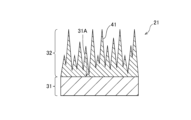
- FIG. 2 is a cross-sectional view schematically illustrating fibers with projections provided in the filter material of the first embodiment.
- FIG. 2 shows a portion of the surface layer of the fiber 31 and the protrusion structure 32 formed on the surface layer, and the same applies to FIGS.
- each protruding fiber 21 comprises a fiber 31 and a protruding structure 32.
- the protrusion structure 32 comprises a plurality of protrusions 41 .
- the fibers 31 may be either chemical fibers or natural fibers.
- the substance constituting the chemical fiber may be either organic or inorganic.
- Organic materials include polyesters, polyamides, polyethylenes, polypropylenes, and the like.
- Inorganic substances are metals, glasses, and the like.
- Metals include aluminum, aluminum alloys, stainless steel, and the like.
- Natural fibers are cotton, hemp, silk and the like.
- a plurality of projections 41 are arranged on the surface 31A of the fiber 31.
- a plurality of protrusions 41 fold over surface 31A.
- a plurality of projections 41 are densely arranged over the entire surface 31A and fill up the surface 31A.
- Each projection 41 has a plate-like shape.
- the term "plate-like” refers to a shape in which the height and depth are longer than the width.
- one protrusion 41 has a width shorter than that of the surface 31A of the fiber 31, and a height direction and depth direction of the surface 31A of the fiber 31 are shorter.
- the plate-like shape may be either a flat plate-like shape or a curved plate-like shape.
- the plurality of protrusions 41 are made of aluminum oxide.
- the protrusion structure 32 can be easily formed on the surface 31A of the fiber 31 .
- FIG. 3 is a cross-sectional view schematically illustrating fibers with protrusions provided in the filter material of the first embodiment and microorganisms adhering to the fibers with protrusions.
- the protruding structure 32 physically damages the microorganisms 51 adhering to the protruding structure 32 to inactivate the microorganisms 51 .
- the filter material 1 has antimicrobial properties.
- the damaged microorganisms 51 are bacteria, viruses, etc., and the filter material 1 has antibacterial properties, antiviral properties, and the like.
- 4 and 5 are electron microscope images of fibers with projections provided in the filter material of the first embodiment and E. coli adhered to the fibers with projections.
- the white portions included in the electron microscope images of FIGS. 4 and 5 are the tips of the projections 41.
- the E. coli 52 attached to the fiber 21 with projections is physically damaged and does not retain its original shape. Therefore, from FIGS. 4 and 5, it can be understood that the filter material 1 provided with the fibers 21 with a large number of protrusions has anti-coliformity.
- Each protrusion 41 is a fine protrusion having a size similar to or smaller than the size of the microorganism 51 .
- the shape, size and orientation of the plurality of protrusions 41 are random.
- the positions at which the plurality of projections 41 are arranged are random.
- Adjacent protrusions 41 may overlap in the cross section of the fiber 21 with protrusions when the fiber 21 with protrusions is cut at an arbitrary position.
- the aspect ratio indicating the ratio of the height of each projection 41 to the thickness of each projection 41 is desirably 1 or more. This makes it easier for the protrusion structure 32 to physically damage the microorganism 51 . Thereby, the antimicrobial property of the filter material 1 can be improved.
- Each projection 41 is desirably a structure having a sharp blade-like shape. Therefore, the thickness of the tip of each projection 41 is desirably thinner than the thickness of the base of each projection 41 . This makes it easier for the protrusion structure 32 to physically damage the microorganism 51 . Thereby, the antimicrobial property of the filter material 1 can be improved.
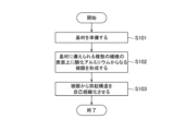
- FIG. 6 is a flow chart showing the flow of manufacturing the filter material of the first embodiment.
- steps S101 to S103 shown in FIG. 6 are executed.
- a base material is prepared.
- the prepared base material is a fiber aggregate comprising a plurality of fibers 31 .
- a coating made of aluminum oxide is formed on the surfaces 31A of the plurality of fibers 31 provided on the prepared base material. Thereby, a fiber aggregate comprising a plurality of coated fibers is obtained.
- the coating can be formed, for example, by a sol-gel method using aluminum alkoxide.
- the protruding structures 32 are self-assembled from the formed film.
- the protruding structures 32 are self-assembled, for example, by immersing the resulting fiber assembly comprising a plurality of coated fibers in warm water.
- the temperature of hot water is, for example, 60°C.
- the filter material 1 may be manufactured by other manufacturing methods.
- FIG. 7 is a cross-sectional view schematically illustrating fibers with projections provided in the filter material of the second embodiment.
- FIG. 8 is an electron microscope image of fibers with protrusions provided in the filter material of the second embodiment.
- the tips of the plurality of protrusions 41 have an average interval of 100 nm or more and 300 nm or less.
- the average distance between the tips of the plurality of protrusions 41 is obtained by cutting the protrusion-attached fiber 21 at an arbitrary position and observing the cross section of the protrusion-attached fiber 21 with an electron microscope.
- a projection 41 having a height of 9 times or more can be specified, and the specified projection 41 can be obtained as a target.
- the average distance can be obtained by identifying projections 41 having a height of 0.9 times or more the height of the highest projection 41 in an arbitrary cross section with a length of 5 ⁇ m and measuring these distances. .
- the fiber 21 has even one point having the average interval in the measurement of the average interval, it is considered that the fiber 21 has a plurality of points having such an average interval in consideration of the manufacturing method.
- the fiber 21 that satisfies the condition of the average spacing in the measurement can damage the bacteria.
- the average distance is measured at a plurality of arbitrary points, and more than half of the points satisfy the average distance requirements. For example, if the average interval is measured at any of 10 points, and if the average interval is satisfied at 5 points or more, which is more than half of the points, it is considered that the bacteria can reliably damage the cells. desirable because
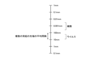
- FIG. 9 is a diagram explaining the size relationship between the average distance between the tips of a plurality of projections provided in the filter material of the second embodiment and the sizes of bacteria and viruses.
- the size of bacteria is generally around 0.001 mm (1000 nm).
- the above-described average distance between the tips of the projections 41 of 100 nm or more and 300 nm or less is slightly smaller than the size of bacteria. This makes it easier to physically damage the bacteria adhering to the fibers with projections 21 . Thereby, the antibacterial property of the filter material 1 can be improved.
- the average distance between the tips of the plurality of projections 41 can be adjusted by adjusting the time and temperature of the warm water for immersing the fiber assembly in step S103.
- FIG. 10 is a cross-sectional view schematically illustrating fibers with protrusions provided in the filter material of the third embodiment.
- FIG. 11 is an electron microscope image of fibers with projections provided in the filter material of the third embodiment.
- the tips of the multiple projections 41 have an average interval of 10 nm or more and 100 nm or less.
- the method for obtaining the average interval in the third embodiment is the same as the method for obtaining the average interval in the second embodiment.
- FIG. 12 is a diagram for explaining the size relationship between the average distance between the tips of a plurality of protrusions provided in the filter material of the third embodiment and the sizes of bacteria and viruses.
- the size of viruses is generally around 10 nm to 100 nm. Therefore, the average distance between the tips of the multiple projections 41, which is 10 nm or more and 100 nm or less, is about the same as the size of the virus. This makes it easier to physically damage the viruses adhering to the fibers with projections 21 . Thereby, the antiviral property of the filter material 1 can be improved.
- the average distance between the tips of the plurality of projections 41 can be adjusted by adjusting the time and temperature of the warm water for immersing the fiber assembly in step S103.
- FIG. 13 is a diagram schematically illustrating the filter material of the fourth embodiment.
- the filter material 1 comprises two fiber aggregates 61 and 62, as shown in FIG.
- the filter material 1 may have three or more fiber aggregates.
- Each of the fiber aggregates 61 and 62 has a layered shape.
- the fiber aggregates 61 and 62 are laminated. As a result, the fluid 71 passing through the filter material 1 passes through the fiber aggregates 61 and 62 in sequence.
- the fiber assemblies 61 and 62 include the fiber assembly 11 having a plurality of fibers 21 with projections. Thereby, the filter material 1 can be provided with antimicrobial properties.
- the number of fiber aggregates 11 included may be one, or may be two or more.
- the fiber aggregates 61 and 62 have fiber properties different from each other.
- Fiber properties include, for example, at least one selected from the group consisting of fiber diameter and basis weight.
- FIG. 14 is a diagram schematically illustrating a filter material of an example of the fourth embodiment.
- the filter material 1 comprises fiber aggregates 61 and 62 and a cured adhesive 63, as shown in FIG.
- the fiber aggregates 61 and 62 are adhered to each other via the cured adhesive 63 .
- the second fiber assembly 62 has a fiber diameter smaller than that of the first fiber assembly 61.
- a second fiber assembly 62 having a relatively small fiber diameter is the fiber assembly 11 including a plurality of fibers 21 with projections.
- the filter material 1 is made by applying an adhesive to one side of a first fiber assembly 11 having a relatively large fiber diameter, and attaching the first fiber assembly 11 and the second fiber assembly via the applied adhesive. 11 and hardening the adhesive to change it into the hardened adhesive 63 .
- FIG. 15 is a diagram schematically illustrating the filter material of the fifth embodiment.
- the filter material 1 comprises two fiber aggregates 91 and 92, as shown in FIG.
- the filter material 1 may have three or more fiber aggregates.
- Each of the fiber aggregates 91 and 92 has a layered shape.
- the fiber aggregates 91 and 92 are laminated. As a result, the fluid 101 passing through the filter material 1 passes through the fiber aggregates 91 and 92 in sequence.
- the fiber aggregates 91 and 92 have the same fiber properties.
- Fiber properties include, for example, at least one selected from the group consisting of fiber diameter and basis weight.
- the fiber aggregates 91 and 92 may have fiber properties different from each other.
- Each of the fiber aggregates 91 and 92 is the fiber aggregate 11 including a plurality of fibers 21 with projections. However, the plurality of fiber aggregates 11 have different average distances between the tips of the plurality of protrusions 41 .
- microorganism 111 and 112 inactivated by the fiber aggregates 91 and 92 can be made different from each other.
- microorganism 111 can be a bacterium and microorganism 112 can be a virus.
- FIG. 16 is a diagram schematically illustrating a filter material of an example of the fifth embodiment.
- the filter material 1 comprises fiber aggregates 91 and 92 and a cured adhesive 93, as shown in FIG.
- the fiber aggregates 91 and 92 are adhered to each other via a cured adhesive 93.
- Each of the fiber aggregates 91 and 92 is the fiber aggregate 11 including a plurality of fibers 21 with projections.
- the second fiber assembly 92 has an average distance between the tips of the projections 41 that is smaller than the average distance between the tips of the projections 41 of the first fiber assembly 91 .
- the filter material 1 is made by applying an adhesive to one side of one of the first fiber assembly 91 and the second fiber assembly 92, and applying the adhesive to the first fiber assembly 91 and the second fiber assembly 92. It can be manufactured by bonding the second fiber assembly 91 together and curing the adhesive to change it into the cured adhesive 93 .
- the sixth embodiment employs the same configuration as that employed in the first embodiment, except for the points that are not explained.
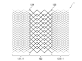
- FIG. 17 is a diagram schematically illustrating the filter material of the sixth embodiment.
- the filter material 1 comprises three fiber aggregates 121, 122 and 123, as shown in FIG.
- the filter material 1 may comprise four or more fiber aggregates.
- Each of the fiber aggregates 121, 122 and 123 has a layered shape.
- the fiber aggregates 121, 122 and 123 are laminated. As a result, the fluid passing through the filter material 1 passes through the fiber aggregates 121, 122 and 123 in sequence.
- the fiber aggregates 121, 122 and 123 include the fiber aggregate 11 having a plurality of fibers 21 with projections. Thereby, the filter material 1 can be provided with antimicrobial properties.
- the number of fiber aggregates 11 included may be one, or may be two or more.
- the fiber assemblies 121, 122 and 123 include the fiber assemblies 121 and 123 having the first fiber properties and the fiber assembly 122 having the second fiber properties.
- the first fiber property and the second fiber property are different from each other.
- Fiber properties include, for example, at least one selected from the group consisting of fiber diameter and basis weight.
- the fiber assemblies 121 and 123 having the first fiber characteristics and the fiber assembly 122 having the second fiber characteristics are alternately laminated.
- the stiffness of the fiber assemblies 121 and 123 having the first fiber properties and the stiffness of the fiber assembly 122 having the second fiber properties may differ from each other.
- the expansion due to change in temperature of the fiber assemblies 121 and 123 having the first fiber properties and the expansion due to change in temperature for the fiber assembly 122 having the second fiber properties may differ from each other.
- the temperature change shrinkage of the fiber assemblies 121 and 123 having the first fiber properties and the temperature change shrinkage of the fiber assembly 122 having the second fiber properties may differ from each other.
- FIG. 18 is a diagram schematically illustrating a filter material of an example of the sixth embodiment.
- the filter material 1 includes fiber aggregates 121, 122 and 123 and adhesive cured products 124 and 125.
- the fiber aggregates 121 and 122 are adhered to each other via the cured adhesive 124 .
- the fiber aggregates 122 and 123 are adhered to each other via a cured adhesive 125 .
- the second fiber assembly 122 has a fiber diameter smaller than that of the first fiber assemblies 121 and 123.
- the second fiber assembly 122 having a relatively small fiber diameter is the fiber assembly 11 including a plurality of fibers 21 with projections.
- the filter material 1 is made by applying an adhesive to one side of the first fiber aggregates 121 and 123 having relatively large fiber diameters, and attaching the fiber aggregates 121 and 122 through the adhesive applied to the fiber aggregates 121 . are bonded together, and the fiber assemblies 123 and 122 are bonded together via the adhesive applied to the fiber assembly 123, and the adhesive applied to the fiber assemblies 121 and 123 is changed into adhesive cured products 124 and 125, respectively. It can be manufactured by
- FIG. 19 is a diagram schematically illustrating a filter material of another example of the sixth embodiment.
- the second fiber assemblies 121 and 123 have a fiber diameter smaller than the fiber diameter of the first fiber assembly 122.
- Each of the second fiber aggregates 121 and 123 having relatively small fiber diameters is the fiber aggregate 11 including a plurality of fibers 21 with projections.
- the filter material 1 is made by applying an adhesive to both surfaces of the first fiber assembly 122 having a relatively large fiber diameter, and by applying the adhesive to one surface of the first fiber assembly 122, thereby separating the fiber assembly. 121 and 122 are pasted together, fiber assemblies 123 and 122 are pasted together via an adhesive applied to the other surface of the first fiber assembly 122, and applied to one surface and the other surface of the first fiber assembly 122. can be produced by changing the cured adhesive into cured adhesives 124 and 125, respectively.
- FIG. 20 is a perspective view schematically illustrating an air filter of a seventh embodiment.
- the air filter 131 of the seventh embodiment illustrated in FIG. 20 allows air to pass through and inactivates the microorganisms 51 contained in the air to pass through.
- the air filter 131 includes a filter material 141 and an outer frame 142.
- the air filter 131 has an adhesive layer (not shown).
- the filter material 141 is any one of the filter materials 1 of the first through sixth embodiments.
- the outer frame 142 holds the filter material 141 .
- the adhesive layer fixes the outer frame 142 to the filter material 141 .
- the outer frame 142 and the adhesive layer may be omitted.
- the outer peripheral surface of the filter material 141 is subjected to a process for suppressing the detachment of the fibers with projections 21, such as a process of pressing the fibers with projections 21. applied.
- the filter material 141 may be subjected to electrification processing to improve the dust collection performance.
- FIG. 21 is a perspective view schematically illustrating an air conditioner of an eighth embodiment.
- the air conditioner 151 illustrated in FIG. 21 has an air cleaning function for cleaning air and a humidification function for humidifying air. Therefore, the air conditioner 151 operates as an air cleaner and a humidifier.
- the air conditioner 151 may have functions other than the air cleaning function and the humidifying function. For example, the air conditioner 151 may have cooling, heating, dehumidification, ion supply functions, and the like. Air conditioner 151 may not have a humidifying function.
- the air conditioner 151 includes a blower fan 161, a pre-filter 162, an antibacterial HEPA filter 163, a deodorizing filter 164 and a humidifying filter 165.
- the air conditioner 151 has an outer frame (not shown). The outer frame is formed with an inlet and an outlet.
- the blower fan 161 generates a flow of air that is sucked into the suction port, passes through the pre-filter 162, the antibacterial HEPA filter 163, the deodorizing filter 164 and the humidifying filter 165, and is blown out from the outlet.
- the pre-filter 162 allows air to pass through and removes coarse dust contained in the air to pass through from the air.
- the antibacterial HEPA filter 163 allows air to pass through and removes dust contained in the air to pass through.
- the deodorizing filter 164 allows air to pass through and removes odor components contained in the passing air from the air.
- the humidification filter 165 allows air to pass through and humidifies the air to pass through.
- the antibacterial HEPA filter 163 has the air filter 131 of the seventh embodiment. As a result, the microorganisms 51 contained in the air passing through the antibacterial HEPA filter 163 can be removed and the microorganisms 51 can be inactivated.
- a dust collection filter that removes dust other than the antibacterial HEPA filter 163 may include the air filter 131 .
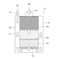
- FIG. 22 is a diagram schematically illustrating a water purifier of a ninth embodiment.
- the water purifier 171 of the ninth embodiment illustrated in FIG. 22 purifies the supplied raw water 181 to produce purified water 182 and supplies the produced purified water 182 .
- the water purifier 171 includes a housing 191, a nonwoven fabric 192, an activated carbon layer 193, a ceramic particle layer 194 and an antibacterial/antiviral layer 195.
- a raw water inlet 201 , a purified water outlet 202 and a channel 203 are formed in the housing 191 .
- the flow path 203 extends from the raw water inlet 201 to the purified water outlet 202 and guides water 211 from the raw water inlet 201 to the purified water outlet 202 .
- the nonwoven fabric 192 allows water 211 to pass through and removes dust contained in the water 211 to pass through from the water 211 .
- the activated carbon layer 193 is made of activated carbon.
- the activated carbon layer 193 allows water 211 to pass through and removes chlorine, organic chlorine compounds, and the like contained in the water 211 to be passed through from the water 211 .
- the ceramic particle layer 194 is made of ceramic particles.
- the ceramic particle layer 194 allows the water 211 to pass through and removes various impurities contained in the water 211 to be passed through the water 211 .
- the antibacterial/antiviral layer 195 comprises a water filter comprising the filter material 1 of any one of the first to sixth embodiments.
- the antibacterial/antiviral layer 195 allows the water 211 to pass through and inactivates the microorganisms 51 contained in the water 211 that is passed through.
- General chemical fibers are hydrophobic.
- the fiber 21 with projections has hydrophilicity because the outermost surface thereof is made of hydrophilic aluminum oxide. This reduces the water pressure required to force the water 211 through the filter material 1 and the antibacterial/antiviral layer 195 .
- the microorganisms 51 are inactivated by chemicals such as antibacterial agents, the chemicals may be eluted into the water 211 .
- the microorganisms 51 are inactivated by the filter material 1, the microorganisms 51 are physically inactivated, so that the elution of undesirable components into the water 211 can be suppressed.
- the carrier that supports the catalyst, and the light source that irradiates the catalyst with light elements such as the light source that make the water purifier larger and more complicated are required.
- the microorganisms 51 are inactivated by the filter material 1, the need for such elements can be suppressed.
- the present disclosure is not limited to the above embodiments, but has substantially the same configuration, the same effect, or the same purpose as the configuration shown in the above embodiment. can be replaced with
Landscapes
- Chemical & Material Sciences (AREA)
- Chemical Kinetics & Catalysis (AREA)
- Life Sciences & Earth Sciences (AREA)
- Geology (AREA)
- Inorganic Chemistry (AREA)
- Health & Medical Sciences (AREA)
- Epidemiology (AREA)
- Animal Behavior & Ethology (AREA)
- General Health & Medical Sciences (AREA)
- Public Health (AREA)
- Veterinary Medicine (AREA)
- Hydrology & Water Resources (AREA)
- Engineering & Computer Science (AREA)
- Environmental & Geological Engineering (AREA)
- Water Supply & Treatment (AREA)
- Organic Chemistry (AREA)
- Filtering Materials (AREA)
Priority Applications (3)
| Application Number | Priority Date | Filing Date | Title |
|---|---|---|---|
| CN202280093107.8A CN118804787A (zh) | 2022-03-04 | 2022-12-28 | 过滤材料、空气过滤器、空气调节机、水过滤器以及净水器 |
| JP2024504378A JPWO2023166841A1 (https=) | 2022-03-04 | 2022-12-28 | |
| US18/843,290 US20250177896A1 (en) | 2022-03-04 | 2022-12-28 | Filter material, air filter, air conditioner, water filter, and water cleaner |
Applications Claiming Priority (2)
| Application Number | Priority Date | Filing Date | Title |
|---|---|---|---|
| JP2022033233 | 2022-03-04 | ||
| JP2022-033233 | 2022-03-04 |
Publications (1)
| Publication Number | Publication Date |
|---|---|
| WO2023166841A1 true WO2023166841A1 (ja) | 2023-09-07 |
Family
ID=87883685
Family Applications (1)
| Application Number | Title | Priority Date | Filing Date |
|---|---|---|---|
| PCT/JP2022/048437 Ceased WO2023166841A1 (ja) | 2022-03-04 | 2022-12-28 | フィルタ材、エアフィルタ、空気調和機、ウオータフィルタ及び浄水器 |
Country Status (4)
| Country | Link |
|---|---|
| US (1) | US20250177896A1 (https=) |
| JP (1) | JPWO2023166841A1 (https=) |
| CN (1) | CN118804787A (https=) |
| WO (1) | WO2023166841A1 (https=) |
Citations (4)
| Publication number | Priority date | Publication date | Assignee | Title |
|---|---|---|---|---|
| JP2006524177A (ja) * | 2003-03-07 | 2006-10-26 | セルドン テクノロジーズ,エルエルシー | ナノ物質による流体の浄化 |
| JP2009235660A (ja) * | 2008-03-05 | 2009-10-15 | Nissan Motor Co Ltd | 触媒付き繊維集合体、その製造方法及び排ガス用浄化装置 |
| WO2015088003A1 (ja) * | 2013-12-13 | 2015-06-18 | 株式会社フジコー | 空気清浄用フィルタ及びそれを備えた空気清浄機 |
| JP2018003048A (ja) * | 2016-06-28 | 2018-01-11 | 公立大学法人首都大学東京 | 陽極酸化ポーラスアルミナ及びその製造方法、並びに陽極酸化ポーラスアルミナスルーホールメンブレン、その製造方法 |
Family Cites Families (6)
| Publication number | Priority date | Publication date | Assignee | Title |
|---|---|---|---|---|
| JPH1147255A (ja) * | 1997-07-31 | 1999-02-23 | Tamapatsuku Kk | 空気清浄器 |
| JP3540964B2 (ja) * | 1999-07-29 | 2004-07-07 | 株式会社ノリタケカンパニーリミテド | 光触媒フィルター及びその製造方法 |
| US7390343B2 (en) * | 2005-09-12 | 2008-06-24 | Argonide Corporation | Drinking water filtration device |
| US8678201B2 (en) * | 2010-06-04 | 2014-03-25 | Goodrich Corporation | Aircraft potable water system |
| SG11201406558RA (en) * | 2012-04-17 | 2014-11-27 | Ngee Ann Polytechnic | Filtration medium with electrospun metal oxide nanofiber layer |
| JP2019033866A (ja) * | 2017-08-14 | 2019-03-07 | 株式会社バイオシールドサイエンス | 二価鉄系消臭抗菌剤 |
-
2022
- 2022-12-28 JP JP2024504378A patent/JPWO2023166841A1/ja active Pending
- 2022-12-28 WO PCT/JP2022/048437 patent/WO2023166841A1/ja not_active Ceased
- 2022-12-28 CN CN202280093107.8A patent/CN118804787A/zh active Pending
- 2022-12-28 US US18/843,290 patent/US20250177896A1/en active Pending
Patent Citations (4)
| Publication number | Priority date | Publication date | Assignee | Title |
|---|---|---|---|---|
| JP2006524177A (ja) * | 2003-03-07 | 2006-10-26 | セルドン テクノロジーズ,エルエルシー | ナノ物質による流体の浄化 |
| JP2009235660A (ja) * | 2008-03-05 | 2009-10-15 | Nissan Motor Co Ltd | 触媒付き繊維集合体、その製造方法及び排ガス用浄化装置 |
| WO2015088003A1 (ja) * | 2013-12-13 | 2015-06-18 | 株式会社フジコー | 空気清浄用フィルタ及びそれを備えた空気清浄機 |
| JP2018003048A (ja) * | 2016-06-28 | 2018-01-11 | 公立大学法人首都大学東京 | 陽極酸化ポーラスアルミナ及びその製造方法、並びに陽極酸化ポーラスアルミナスルーホールメンブレン、その製造方法 |
Also Published As
| Publication number | Publication date |
|---|---|
| JPWO2023166841A1 (https=) | 2023-09-07 |
| CN118804787A (zh) | 2024-10-18 |
| US20250177896A1 (en) | 2025-06-05 |
Similar Documents
| Publication | Publication Date | Title |
|---|---|---|
| US9943796B2 (en) | Multi layer pleatable filter medium | |
| WO2009085645A2 (en) | Joined filter media pleat packs | |
| WO2008098185A1 (en) | Combination filter element | |
| CA3056313C (en) | Corrugated filtration media for polarizing air cleaner | |
| JP2005279429A (ja) | ケミカルフィルタ及びその製造方法 | |
| KR20090109718A (ko) | 다층의 공기정화용 기체 여과막 | |
| WO2023166841A1 (ja) | フィルタ材、エアフィルタ、空気調和機、ウオータフィルタ及び浄水器 | |
| JP2014151299A (ja) | フィルター用濾材およびエアフィルター | |
| KR20140002111A (ko) | 바이러스 살균 필터 및 이를 이용한 마스크 | |
| JPH1085558A (ja) | 空気清浄装置 | |
| WO2019230983A1 (ja) | フィルタ濾材とこれを備えるフィルタユニット | |
| CN107344072B (zh) | 低压损过滤膜 | |
| JP2022009716A (ja) | エアフィルター濾材及びエアフィルター | |
| JP2005279430A (ja) | ケミカルフィルタの製造方法 | |
| JP4195851B2 (ja) | 空気清浄機用フィルタ | |
| JP6615136B2 (ja) | ハニカムコアの光触媒システム | |
| JP6955645B1 (ja) | 摩擦帯電不織布、および、その製造方法 | |
| JP3983880B2 (ja) | エアーフィルター | |
| JP7415919B2 (ja) | 濾材及びフィルターユニット | |
| US7264044B2 (en) | Heat exchange structure | |
| KR20230076979A (ko) | 공기정화용 항균 탈취 복합부직포 및 그의 제조방법 | |
| US20120090471A1 (en) | Scenting Device For HVAC Systems And Method Of Making A Scenting Device | |
| JP2002228382A (ja) | 熱交換器 | |
| JP2015167913A (ja) | エアフィルターユニット | |
| JP7356972B2 (ja) | フィルタ濾材とこれを備えるフィルタユニット |
Legal Events
| Date | Code | Title | Description |
|---|---|---|---|
| 121 | Ep: the epo has been informed by wipo that ep was designated in this application |
Ref document number: 22929983 Country of ref document: EP Kind code of ref document: A1 |
|
| ENP | Entry into the national phase |
Ref document number: 2024504378 Country of ref document: JP Kind code of ref document: A |
|
| WWE | Wipo information: entry into national phase |
Ref document number: 18843290 Country of ref document: US |
|
| WWE | Wipo information: entry into national phase |
Ref document number: 202280093107.8 Country of ref document: CN |
|
| NENP | Non-entry into the national phase |
Ref country code: DE |
|
| 122 | Ep: pct application non-entry in european phase |
Ref document number: 22929983 Country of ref document: EP Kind code of ref document: A1 |
|
| WWP | Wipo information: published in national office |
Ref document number: 18843290 Country of ref document: US |