WO2023166841A1 - Filter material, air filter, air conditioner, water filter, and water cleaner - Google Patents
Filter material, air filter, air conditioner, water filter, and water cleaner Download PDFInfo
- Publication number
- WO2023166841A1 WO2023166841A1 PCT/JP2022/048437 JP2022048437W WO2023166841A1 WO 2023166841 A1 WO2023166841 A1 WO 2023166841A1 JP 2022048437 W JP2022048437 W JP 2022048437W WO 2023166841 A1 WO2023166841 A1 WO 2023166841A1
- Authority
- WO
- WIPO (PCT)
- Prior art keywords
- fiber
- filter material
- filter
- projections
- fibers
- Prior art date
Links
Images


Classifications
-
- A—HUMAN NECESSITIES
- A61—MEDICAL OR VETERINARY SCIENCE; HYGIENE
- A61L—METHODS OR APPARATUS FOR STERILISING MATERIALS OR OBJECTS IN GENERAL; DISINFECTION, STERILISATION OR DEODORISATION OF AIR; CHEMICAL ASPECTS OF BANDAGES, DRESSINGS, ABSORBENT PADS OR SURGICAL ARTICLES; MATERIALS FOR BANDAGES, DRESSINGS, ABSORBENT PADS OR SURGICAL ARTICLES
- A61L9/00—Disinfection, sterilisation or deodorisation of air
- A61L9/16—Disinfection, sterilisation or deodorisation of air using physical phenomena
-
- B—PERFORMING OPERATIONS; TRANSPORTING
- B01—PHYSICAL OR CHEMICAL PROCESSES OR APPARATUS IN GENERAL
- B01D—SEPARATION
- B01D39/00—Filtering material for liquid or gaseous fluids
- B01D39/14—Other self-supporting filtering material ; Other filtering material
-
- C—CHEMISTRY; METALLURGY
- C02—TREATMENT OF WATER, WASTE WATER, SEWAGE, OR SLUDGE
- C02F—TREATMENT OF WATER, WASTE WATER, SEWAGE, OR SLUDGE
- C02F1/00—Treatment of water, waste water, or sewage
- C02F1/28—Treatment of water, waste water, or sewage by sorption
Definitions
- the present disclosure relates to filter materials, air filters, air conditioners, water filters and water purifiers.
- Patent Document 1 discloses an air cleaning filter.
- the air purifying filter comprises a fiber aggregate formed in a non-woven fabric of fibers made of aluminum or an aluminum alloy, and a fiber aggregate made of aluminum or an aluminum alloy having a plurality of holes and covering both surfaces of the fiber aggregate.
- a shape-retaining member provided, recesses formed by roughening at least the surface of the fibers on the upstream side of the fiber assembly, and exposed from the outer surface of the shape-retaining member and the hole of the shape-retaining member. and a skin layer of an alumite layer or a boehmite layer formed on the outer surface of the fiber assembly (Paragraph 0006).
- the air cleaning filter disclosed in Patent Document 1 may not have sufficient antibacterial properties, antiviral properties, and the like.
- An object of one aspect of the present disclosure is to provide a filter, an air filter, an air conditioner, a water filter, and a water purifier that have high antimicrobial properties.
- a filter material includes a fiber aggregate including a plurality of fibers with projections, each fiber having projections having a surface and a plate-like shape disposed on the surface and containing aluminum oxide.
- a plurality of protrusions comprising:
- An air filter according to another aspect of the present disclosure includes the filter material according to one aspect of the present disclosure.
- An air conditioner according to another aspect of the present disclosure includes an air filter according to another aspect of the present disclosure.
- a water filter according to another aspect of the present disclosure includes the filter material according to one aspect of the present disclosure.
- a water purifier of another aspect of the present disclosure includes a water filter of another aspect of the present disclosure.
- FIG. 2 is a plan view schematically illustrating the filter material of the first embodiment
- FIG. 3 is a cross-sectional view schematically illustrating fibers with projections provided in the filter material of the first embodiment.
- FIG. 2 is a cross-sectional view schematically illustrating fibers with projections provided in the filter material of the first embodiment and microorganisms adhering to the fibers with projections.
- 4 is an electron microscope image of fibers with projections provided in the filter material of the first embodiment and E. coli adhering to the fibers with projections.
- 4 is an electron microscope image of fibers with projections provided in the filter material of the first embodiment and E. coli adhering to the fibers with projections. 4 is a flow chart showing the flow of manufacturing the filter material of the first embodiment.
- FIG. 4 is a cross-sectional view schematically illustrating fibers with protrusions provided in the filter material of the second embodiment.
- 4 is an electron microscope image of fibers with protrusions provided in the filter material of the second embodiment.
- FIG. 10 is a diagram for explaining the size relationship between the average distance between the tips of a plurality of projections provided in the filter material of the second embodiment and the sizes of bacteria and viruses;
- FIG. 10 is a cross-sectional view schematically illustrating fibers with protrusions provided in the filter material of the third embodiment.
- 11 is an electron microscope image of fibers with projections provided in the filter material of the third embodiment.
- FIG. 11 is a diagram for explaining the size relationship between the average distance between the tips of a plurality of protrusions provided in the filter material of the third embodiment and the sizes of bacteria and viruses; It is a figure which illustrates the filter material of 4th Embodiment typically.
- FIG. 11 is a diagram schematically illustrating a filter material of an example of the fourth embodiment; It is a figure which illustrates the filter material of 5th Embodiment typically.
- FIG. 11 is a diagram schematically illustrating a filter material of an example of the fifth embodiment; It is a figure which illustrates the filter material of 6th Embodiment typically.
- FIG. 11 is a diagram schematically illustrating a filter material of an example of the sixth embodiment; FIG.
- FIG. 11 is a diagram schematically illustrating filter material of another example of the sixth embodiment; It is a perspective view which illustrates the air filter of 7th Embodiment typically. It is a perspective view which illustrates the air conditioner of 8th Embodiment typically. It is a figure which illustrates the water purifier of 9th Embodiment typically.
- FIG. 1 is a plan view schematically illustrating a filter material of a first embodiment.
- the filter material 1 of the first embodiment illustrated in FIG. 1 allows fluid to pass through and inactivates microorganisms contained in the fluid to pass through.
- the fluid that is passed through is water, air, or the like.
- Microorganisms to be inactivated are bacteria, viruses and the like.
- the filter material 1 includes a fiber assembly 11. As shown in FIG. The fiber assembly 11 has a plurality of fibers 21 with projections.
- the fibers 21 with multiple protrusions are entangled. Gaps 11A are formed between the plurality of fibers 21 with projections to allow fluid to pass therethrough.
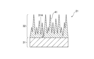
- FIG. 2 is a cross-sectional view schematically illustrating fibers with projections provided in the filter material of the first embodiment.
- FIG. 2 shows a portion of the surface layer of the fiber 31 and the protrusion structure 32 formed on the surface layer, and the same applies to FIGS.
- each protruding fiber 21 comprises a fiber 31 and a protruding structure 32.
- the protrusion structure 32 comprises a plurality of protrusions 41 .
- the fibers 31 may be either chemical fibers or natural fibers.
- the substance constituting the chemical fiber may be either organic or inorganic.
- Organic materials include polyesters, polyamides, polyethylenes, polypropylenes, and the like.
- Inorganic substances are metals, glasses, and the like.
- Metals include aluminum, aluminum alloys, stainless steel, and the like.
- Natural fibers are cotton, hemp, silk and the like.
- a plurality of projections 41 are arranged on the surface 31A of the fiber 31.
- a plurality of protrusions 41 fold over surface 31A.
- a plurality of projections 41 are densely arranged over the entire surface 31A and fill up the surface 31A.
- Each projection 41 has a plate-like shape.
- the term "plate-like” refers to a shape in which the height and depth are longer than the width.
- one protrusion 41 has a width shorter than that of the surface 31A of the fiber 31, and a height direction and depth direction of the surface 31A of the fiber 31 are shorter.
- the plate-like shape may be either a flat plate-like shape or a curved plate-like shape.
- the plurality of protrusions 41 are made of aluminum oxide.
- the protrusion structure 32 can be easily formed on the surface 31A of the fiber 31 .
- FIG. 3 is a cross-sectional view schematically illustrating fibers with protrusions provided in the filter material of the first embodiment and microorganisms adhering to the fibers with protrusions.
- the protruding structure 32 physically damages the microorganisms 51 adhering to the protruding structure 32 to inactivate the microorganisms 51 .
- the filter material 1 has antimicrobial properties.
- the damaged microorganisms 51 are bacteria, viruses, etc., and the filter material 1 has antibacterial properties, antiviral properties, and the like.
- 4 and 5 are electron microscope images of fibers with projections provided in the filter material of the first embodiment and E. coli adhered to the fibers with projections.
- the white portions included in the electron microscope images of FIGS. 4 and 5 are the tips of the projections 41.
- the E. coli 52 attached to the fiber 21 with projections is physically damaged and does not retain its original shape. Therefore, from FIGS. 4 and 5, it can be understood that the filter material 1 provided with the fibers 21 with a large number of protrusions has anti-coliformity.
- Each protrusion 41 is a fine protrusion having a size similar to or smaller than the size of the microorganism 51 .
- the shape, size and orientation of the plurality of protrusions 41 are random.
- the positions at which the plurality of projections 41 are arranged are random.
- Adjacent protrusions 41 may overlap in the cross section of the fiber 21 with protrusions when the fiber 21 with protrusions is cut at an arbitrary position.
- the aspect ratio indicating the ratio of the height of each projection 41 to the thickness of each projection 41 is desirably 1 or more. This makes it easier for the protrusion structure 32 to physically damage the microorganism 51 . Thereby, the antimicrobial property of the filter material 1 can be improved.
- Each projection 41 is desirably a structure having a sharp blade-like shape. Therefore, the thickness of the tip of each projection 41 is desirably thinner than the thickness of the base of each projection 41 . This makes it easier for the protrusion structure 32 to physically damage the microorganism 51 . Thereby, the antimicrobial property of the filter material 1 can be improved.
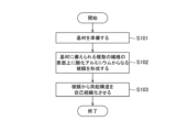
- FIG. 6 is a flow chart showing the flow of manufacturing the filter material of the first embodiment.
- steps S101 to S103 shown in FIG. 6 are executed.
- a base material is prepared.
- the prepared base material is a fiber aggregate comprising a plurality of fibers 31 .
- a coating made of aluminum oxide is formed on the surfaces 31A of the plurality of fibers 31 provided on the prepared base material. Thereby, a fiber aggregate comprising a plurality of coated fibers is obtained.
- the coating can be formed, for example, by a sol-gel method using aluminum alkoxide.
- the protruding structures 32 are self-assembled from the formed film.
- the protruding structures 32 are self-assembled, for example, by immersing the resulting fiber assembly comprising a plurality of coated fibers in warm water.
- the temperature of hot water is, for example, 60°C.
- the filter material 1 may be manufactured by other manufacturing methods.
- FIG. 7 is a cross-sectional view schematically illustrating fibers with projections provided in the filter material of the second embodiment.
- FIG. 8 is an electron microscope image of fibers with protrusions provided in the filter material of the second embodiment.
- the tips of the plurality of protrusions 41 have an average interval of 100 nm or more and 300 nm or less.
- the average distance between the tips of the plurality of protrusions 41 is obtained by cutting the protrusion-attached fiber 21 at an arbitrary position and observing the cross section of the protrusion-attached fiber 21 with an electron microscope.
- a projection 41 having a height of 9 times or more can be specified, and the specified projection 41 can be obtained as a target.
- the average distance can be obtained by identifying projections 41 having a height of 0.9 times or more the height of the highest projection 41 in an arbitrary cross section with a length of 5 ⁇ m and measuring these distances. .
- the fiber 21 has even one point having the average interval in the measurement of the average interval, it is considered that the fiber 21 has a plurality of points having such an average interval in consideration of the manufacturing method.
- the fiber 21 that satisfies the condition of the average spacing in the measurement can damage the bacteria.
- the average distance is measured at a plurality of arbitrary points, and more than half of the points satisfy the average distance requirements. For example, if the average interval is measured at any of 10 points, and if the average interval is satisfied at 5 points or more, which is more than half of the points, it is considered that the bacteria can reliably damage the cells. desirable because
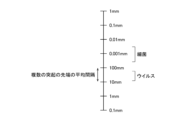
- FIG. 9 is a diagram explaining the size relationship between the average distance between the tips of a plurality of projections provided in the filter material of the second embodiment and the sizes of bacteria and viruses.
- the size of bacteria is generally around 0.001 mm (1000 nm).
- the above-described average distance between the tips of the projections 41 of 100 nm or more and 300 nm or less is slightly smaller than the size of bacteria. This makes it easier to physically damage the bacteria adhering to the fibers with projections 21 . Thereby, the antibacterial property of the filter material 1 can be improved.
- the average distance between the tips of the plurality of projections 41 can be adjusted by adjusting the time and temperature of the warm water for immersing the fiber assembly in step S103.
- FIG. 10 is a cross-sectional view schematically illustrating fibers with protrusions provided in the filter material of the third embodiment.
- FIG. 11 is an electron microscope image of fibers with projections provided in the filter material of the third embodiment.
- the tips of the multiple projections 41 have an average interval of 10 nm or more and 100 nm or less.
- the method for obtaining the average interval in the third embodiment is the same as the method for obtaining the average interval in the second embodiment.
- FIG. 12 is a diagram for explaining the size relationship between the average distance between the tips of a plurality of protrusions provided in the filter material of the third embodiment and the sizes of bacteria and viruses.
- the size of viruses is generally around 10 nm to 100 nm. Therefore, the average distance between the tips of the multiple projections 41, which is 10 nm or more and 100 nm or less, is about the same as the size of the virus. This makes it easier to physically damage the viruses adhering to the fibers with projections 21 . Thereby, the antiviral property of the filter material 1 can be improved.
- the average distance between the tips of the plurality of projections 41 can be adjusted by adjusting the time and temperature of the warm water for immersing the fiber assembly in step S103.
- FIG. 13 is a diagram schematically illustrating the filter material of the fourth embodiment.
- the filter material 1 comprises two fiber aggregates 61 and 62, as shown in FIG.
- the filter material 1 may have three or more fiber aggregates.
- Each of the fiber aggregates 61 and 62 has a layered shape.
- the fiber aggregates 61 and 62 are laminated. As a result, the fluid 71 passing through the filter material 1 passes through the fiber aggregates 61 and 62 in sequence.
- the fiber assemblies 61 and 62 include the fiber assembly 11 having a plurality of fibers 21 with projections. Thereby, the filter material 1 can be provided with antimicrobial properties.
- the number of fiber aggregates 11 included may be one, or may be two or more.
- the fiber aggregates 61 and 62 have fiber properties different from each other.
- Fiber properties include, for example, at least one selected from the group consisting of fiber diameter and basis weight.
- FIG. 14 is a diagram schematically illustrating a filter material of an example of the fourth embodiment.
- the filter material 1 comprises fiber aggregates 61 and 62 and a cured adhesive 63, as shown in FIG.
- the fiber aggregates 61 and 62 are adhered to each other via the cured adhesive 63 .
- the second fiber assembly 62 has a fiber diameter smaller than that of the first fiber assembly 61.
- a second fiber assembly 62 having a relatively small fiber diameter is the fiber assembly 11 including a plurality of fibers 21 with projections.
- the filter material 1 is made by applying an adhesive to one side of a first fiber assembly 11 having a relatively large fiber diameter, and attaching the first fiber assembly 11 and the second fiber assembly via the applied adhesive. 11 and hardening the adhesive to change it into the hardened adhesive 63 .
- FIG. 15 is a diagram schematically illustrating the filter material of the fifth embodiment.
- the filter material 1 comprises two fiber aggregates 91 and 92, as shown in FIG.
- the filter material 1 may have three or more fiber aggregates.
- Each of the fiber aggregates 91 and 92 has a layered shape.
- the fiber aggregates 91 and 92 are laminated. As a result, the fluid 101 passing through the filter material 1 passes through the fiber aggregates 91 and 92 in sequence.
- the fiber aggregates 91 and 92 have the same fiber properties.
- Fiber properties include, for example, at least one selected from the group consisting of fiber diameter and basis weight.
- the fiber aggregates 91 and 92 may have fiber properties different from each other.
- Each of the fiber aggregates 91 and 92 is the fiber aggregate 11 including a plurality of fibers 21 with projections. However, the plurality of fiber aggregates 11 have different average distances between the tips of the plurality of protrusions 41 .
- microorganism 111 and 112 inactivated by the fiber aggregates 91 and 92 can be made different from each other.
- microorganism 111 can be a bacterium and microorganism 112 can be a virus.
- FIG. 16 is a diagram schematically illustrating a filter material of an example of the fifth embodiment.
- the filter material 1 comprises fiber aggregates 91 and 92 and a cured adhesive 93, as shown in FIG.
- the fiber aggregates 91 and 92 are adhered to each other via a cured adhesive 93.
- Each of the fiber aggregates 91 and 92 is the fiber aggregate 11 including a plurality of fibers 21 with projections.
- the second fiber assembly 92 has an average distance between the tips of the projections 41 that is smaller than the average distance between the tips of the projections 41 of the first fiber assembly 91 .
- the filter material 1 is made by applying an adhesive to one side of one of the first fiber assembly 91 and the second fiber assembly 92, and applying the adhesive to the first fiber assembly 91 and the second fiber assembly 92. It can be manufactured by bonding the second fiber assembly 91 together and curing the adhesive to change it into the cured adhesive 93 .
- the sixth embodiment employs the same configuration as that employed in the first embodiment, except for the points that are not explained.
- FIG. 17 is a diagram schematically illustrating the filter material of the sixth embodiment.
- the filter material 1 comprises three fiber aggregates 121, 122 and 123, as shown in FIG.
- the filter material 1 may comprise four or more fiber aggregates.
- Each of the fiber aggregates 121, 122 and 123 has a layered shape.
- the fiber aggregates 121, 122 and 123 are laminated. As a result, the fluid passing through the filter material 1 passes through the fiber aggregates 121, 122 and 123 in sequence.
- the fiber aggregates 121, 122 and 123 include the fiber aggregate 11 having a plurality of fibers 21 with projections. Thereby, the filter material 1 can be provided with antimicrobial properties.
- the number of fiber aggregates 11 included may be one, or may be two or more.
- the fiber assemblies 121, 122 and 123 include the fiber assemblies 121 and 123 having the first fiber properties and the fiber assembly 122 having the second fiber properties.
- the first fiber property and the second fiber property are different from each other.
- Fiber properties include, for example, at least one selected from the group consisting of fiber diameter and basis weight.
- the fiber assemblies 121 and 123 having the first fiber characteristics and the fiber assembly 122 having the second fiber characteristics are alternately laminated.
- the stiffness of the fiber assemblies 121 and 123 having the first fiber properties and the stiffness of the fiber assembly 122 having the second fiber properties may differ from each other.
- the expansion due to change in temperature of the fiber assemblies 121 and 123 having the first fiber properties and the expansion due to change in temperature for the fiber assembly 122 having the second fiber properties may differ from each other.
- the temperature change shrinkage of the fiber assemblies 121 and 123 having the first fiber properties and the temperature change shrinkage of the fiber assembly 122 having the second fiber properties may differ from each other.
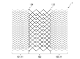
- FIG. 18 is a diagram schematically illustrating a filter material of an example of the sixth embodiment.
- the filter material 1 includes fiber aggregates 121, 122 and 123 and adhesive cured products 124 and 125.
- the fiber aggregates 121 and 122 are adhered to each other via the cured adhesive 124 .
- the fiber aggregates 122 and 123 are adhered to each other via a cured adhesive 125 .
- the second fiber assembly 122 has a fiber diameter smaller than that of the first fiber assemblies 121 and 123.
- the second fiber assembly 122 having a relatively small fiber diameter is the fiber assembly 11 including a plurality of fibers 21 with projections.
- the filter material 1 is made by applying an adhesive to one side of the first fiber aggregates 121 and 123 having relatively large fiber diameters, and attaching the fiber aggregates 121 and 122 through the adhesive applied to the fiber aggregates 121 . are bonded together, and the fiber assemblies 123 and 122 are bonded together via the adhesive applied to the fiber assembly 123, and the adhesive applied to the fiber assemblies 121 and 123 is changed into adhesive cured products 124 and 125, respectively. It can be manufactured by
- FIG. 19 is a diagram schematically illustrating a filter material of another example of the sixth embodiment.
- the second fiber assemblies 121 and 123 have a fiber diameter smaller than the fiber diameter of the first fiber assembly 122.
- Each of the second fiber aggregates 121 and 123 having relatively small fiber diameters is the fiber aggregate 11 including a plurality of fibers 21 with projections.
- the filter material 1 is made by applying an adhesive to both surfaces of the first fiber assembly 122 having a relatively large fiber diameter, and by applying the adhesive to one surface of the first fiber assembly 122, thereby separating the fiber assembly. 121 and 122 are pasted together, fiber assemblies 123 and 122 are pasted together via an adhesive applied to the other surface of the first fiber assembly 122, and applied to one surface and the other surface of the first fiber assembly 122. can be produced by changing the cured adhesive into cured adhesives 124 and 125, respectively.
- FIG. 20 is a perspective view schematically illustrating an air filter of a seventh embodiment.
- the air filter 131 of the seventh embodiment illustrated in FIG. 20 allows air to pass through and inactivates the microorganisms 51 contained in the air to pass through.
- the air filter 131 includes a filter material 141 and an outer frame 142.
- the air filter 131 has an adhesive layer (not shown).
- the filter material 141 is any one of the filter materials 1 of the first through sixth embodiments.
- the outer frame 142 holds the filter material 141 .
- the adhesive layer fixes the outer frame 142 to the filter material 141 .
- the outer frame 142 and the adhesive layer may be omitted.
- the outer peripheral surface of the filter material 141 is subjected to a process for suppressing the detachment of the fibers with projections 21, such as a process of pressing the fibers with projections 21. applied.
- the filter material 141 may be subjected to electrification processing to improve the dust collection performance.
- FIG. 21 is a perspective view schematically illustrating an air conditioner of an eighth embodiment.
- the air conditioner 151 illustrated in FIG. 21 has an air cleaning function for cleaning air and a humidification function for humidifying air. Therefore, the air conditioner 151 operates as an air cleaner and a humidifier.
- the air conditioner 151 may have functions other than the air cleaning function and the humidifying function. For example, the air conditioner 151 may have cooling, heating, dehumidification, ion supply functions, and the like. Air conditioner 151 may not have a humidifying function.
- the air conditioner 151 includes a blower fan 161, a pre-filter 162, an antibacterial HEPA filter 163, a deodorizing filter 164 and a humidifying filter 165.
- the air conditioner 151 has an outer frame (not shown). The outer frame is formed with an inlet and an outlet.
- the blower fan 161 generates a flow of air that is sucked into the suction port, passes through the pre-filter 162, the antibacterial HEPA filter 163, the deodorizing filter 164 and the humidifying filter 165, and is blown out from the outlet.
- the pre-filter 162 allows air to pass through and removes coarse dust contained in the air to pass through from the air.
- the antibacterial HEPA filter 163 allows air to pass through and removes dust contained in the air to pass through.
- the deodorizing filter 164 allows air to pass through and removes odor components contained in the passing air from the air.
- the humidification filter 165 allows air to pass through and humidifies the air to pass through.
- the antibacterial HEPA filter 163 has the air filter 131 of the seventh embodiment. As a result, the microorganisms 51 contained in the air passing through the antibacterial HEPA filter 163 can be removed and the microorganisms 51 can be inactivated.
- a dust collection filter that removes dust other than the antibacterial HEPA filter 163 may include the air filter 131 .
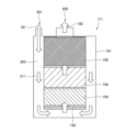
- FIG. 22 is a diagram schematically illustrating a water purifier of a ninth embodiment.
- the water purifier 171 of the ninth embodiment illustrated in FIG. 22 purifies the supplied raw water 181 to produce purified water 182 and supplies the produced purified water 182 .
- the water purifier 171 includes a housing 191, a nonwoven fabric 192, an activated carbon layer 193, a ceramic particle layer 194 and an antibacterial/antiviral layer 195.
- a raw water inlet 201 , a purified water outlet 202 and a channel 203 are formed in the housing 191 .
- the flow path 203 extends from the raw water inlet 201 to the purified water outlet 202 and guides water 211 from the raw water inlet 201 to the purified water outlet 202 .
- the nonwoven fabric 192 allows water 211 to pass through and removes dust contained in the water 211 to pass through from the water 211 .
- the activated carbon layer 193 is made of activated carbon.
- the activated carbon layer 193 allows water 211 to pass through and removes chlorine, organic chlorine compounds, and the like contained in the water 211 to be passed through from the water 211 .
- the ceramic particle layer 194 is made of ceramic particles.
- the ceramic particle layer 194 allows the water 211 to pass through and removes various impurities contained in the water 211 to be passed through the water 211 .
- the antibacterial/antiviral layer 195 comprises a water filter comprising the filter material 1 of any one of the first to sixth embodiments.
- the antibacterial/antiviral layer 195 allows the water 211 to pass through and inactivates the microorganisms 51 contained in the water 211 that is passed through.
- General chemical fibers are hydrophobic.
- the fiber 21 with projections has hydrophilicity because the outermost surface thereof is made of hydrophilic aluminum oxide. This reduces the water pressure required to force the water 211 through the filter material 1 and the antibacterial/antiviral layer 195 .
- the microorganisms 51 are inactivated by chemicals such as antibacterial agents, the chemicals may be eluted into the water 211 .
- the microorganisms 51 are inactivated by the filter material 1, the microorganisms 51 are physically inactivated, so that the elution of undesirable components into the water 211 can be suppressed.
- the carrier that supports the catalyst, and the light source that irradiates the catalyst with light elements such as the light source that make the water purifier larger and more complicated are required.
- the microorganisms 51 are inactivated by the filter material 1, the need for such elements can be suppressed.
- the present disclosure is not limited to the above embodiments, but has substantially the same configuration, the same effect, or the same purpose as the configuration shown in the above embodiment. can be replaced with
Abstract
Provided are a filter, an air filter, an air conditioner, a water filter, and a water cleaner that exhibit high antimicrobial properties. The filter material is provided with a fiber assembly that is composed of multiple protrusion-equipped fibers. Each of the protrusion-equipped fibers comprises: a fiber having a surface; and multiple protrusions that are disposed on said surface, that have a plate-like shape, and that are composed of aluminum oxide.
Description
本開示は、フィルタ材、エアフィルタ、空気調和機、ウオータフィルタ及び浄水器に関する。本出願は、2022年3月4日に日本に出願された特願2022-33233号に優先権を主張し、その内容をここに援用する。
The present disclosure relates to filter materials, air filters, air conditioners, water filters and water purifiers. This application claims priority to Japanese Patent Application No. 2022-33233 filed in Japan on March 4, 2022, the contents of which are incorporated herein.
特許文献1は、空気清浄用フィルタを開示する。当該空気清浄用フィルタは、アルミニウム製又はアルミニウム合金製の繊維で不織布状に形成された繊維集合体と、アルミニウム製又はアルミニウム合金製で複数の孔部を有し前記繊維集合体の両平面に覆設された保形部材と、少なくとも前記繊維集合体の上流側の前記繊維の表面を粗面化して形成された凹部と、前記保形部材の外表面及び前記保形部材の孔部から露出する前記繊維集合体の外表面に形成されたアルマイト層又はベーマイト層の表皮層と、を備える(段落0006)。
Patent Document 1 discloses an air cleaning filter. The air purifying filter comprises a fiber aggregate formed in a non-woven fabric of fibers made of aluminum or an aluminum alloy, and a fiber aggregate made of aluminum or an aluminum alloy having a plurality of holes and covering both surfaces of the fiber aggregate. A shape-retaining member provided, recesses formed by roughening at least the surface of the fibers on the upstream side of the fiber assembly, and exposed from the outer surface of the shape-retaining member and the hole of the shape-retaining member. and a skin layer of an alumite layer or a boehmite layer formed on the outer surface of the fiber assembly (Paragraph 0006).
特許文献1に開示される空気清浄用フィルタは、十分な抗菌性、抗ウイルス性等を有しない場合がある。
The air cleaning filter disclosed in Patent Document 1 may not have sufficient antibacterial properties, antiviral properties, and the like.
本開示は、この問題に鑑みてなされた。本開示の一態様は、高い抗微生物性を有するフィルタ、エアフィルタ、空気調和機、ウオータフィルタ及び浄水器を提供することを目的とする。
This disclosure was made in view of this problem. An object of one aspect of the present disclosure is to provide a filter, an air filter, an air conditioner, a water filter, and a water purifier that have high antimicrobial properties.
本開示の一態様のフィルタ材は、複数の突起付き繊維を備える繊維集合体を備え、各突起付き繊維は、表面を有する繊維と、前記表面上に配置され板状の形状を有し酸化アルミニウムからなる複数の突起と、備える。
A filter material according to one aspect of the present disclosure includes a fiber aggregate including a plurality of fibers with projections, each fiber having projections having a surface and a plate-like shape disposed on the surface and containing aluminum oxide. a plurality of protrusions comprising:
本開示の他の一態様のエアフィルタは、本開示の一態様のフィルタ材を備える。
An air filter according to another aspect of the present disclosure includes the filter material according to one aspect of the present disclosure.
本開示の他の一態様の空気調和機は、本開示の他の一態様のエアフィルタを備える。
An air conditioner according to another aspect of the present disclosure includes an air filter according to another aspect of the present disclosure.
本開示の他の一態様のウオータフィルタは、本開示の一態様のフィルタ材を備える。
A water filter according to another aspect of the present disclosure includes the filter material according to one aspect of the present disclosure.
本開示の他の一態様の浄水器は、本開示の他の一態様のウオータフィルタを備える。
A water purifier of another aspect of the present disclosure includes a water filter of another aspect of the present disclosure.
以下、本開示の実施形態について、図面を参照しつつ説明する。なお、図面については、同一又は同等の要素には同一の符号を付し、重複する説明は省略する。
Hereinafter, embodiments of the present disclosure will be described with reference to the drawings. In the drawings, the same or equivalent elements are denoted by the same reference numerals, and overlapping descriptions are omitted.
1 第1実施形態
図1は、第1実施形態のフィルタ材を模式的に図示する平面図である。 1 First Embodiment FIG. 1 is a plan view schematically illustrating a filter material of a first embodiment.
図1は、第1実施形態のフィルタ材を模式的に図示する平面図である。 1 First Embodiment FIG. 1 is a plan view schematically illustrating a filter material of a first embodiment.
図1に図示される第1実施形態のフィルタ材1は、流体を通過させ、通過させる流体に含まれる微生物を不活性化する。通過させられる流体は、水、空気等である。不活性化される微生物は、細菌、ウイルス等である。
The filter material 1 of the first embodiment illustrated in FIG. 1 allows fluid to pass through and inactivates microorganisms contained in the fluid to pass through. The fluid that is passed through is water, air, or the like. Microorganisms to be inactivated are bacteria, viruses and the like.
図1に図示されるように、フィルタ材1は、繊維集合体11を備える。繊維集合体11は、複数の突起付き繊維21を備える。
As illustrated in FIG. 1, the filter material 1 includes a fiber assembly 11. As shown in FIG. The fiber assembly 11 has a plurality of fibers 21 with projections.
複数の突起付き繊維21は、絡み合っている。複数の突起付き繊維21の間には、流体を通過させる間隙11Aが形成される。
The fibers 21 with multiple protrusions are entangled. Gaps 11A are formed between the plurality of fibers 21 with projections to allow fluid to pass therethrough.
図2は、第1実施形態のフィルタ材に備えられる突起付き繊維を模式的に図示する断面図である。図2では、繊維31の表層の一部分と、当該表層上に形成される突起構造32とが示されており、図3、7、10においても同様である。
FIG. 2 is a cross-sectional view schematically illustrating fibers with projections provided in the filter material of the first embodiment. FIG. 2 shows a portion of the surface layer of the fiber 31 and the protrusion structure 32 formed on the surface layer, and the same applies to FIGS.
図2に図示されるように、各突起付き繊維21は、繊維31及び突起構造32を備える。突起構造32は、複数の突起41を備える。
As illustrated in FIG. 2, each protruding fiber 21 comprises a fiber 31 and a protruding structure 32. As shown in FIG. The protrusion structure 32 comprises a plurality of protrusions 41 .
繊維31は、化学繊維及び天然繊維のいずれであってもよい。化学繊維を構成する物質は、有機物及び無機物のいずれであってもよい。有機物は、ポリエステル、ポリアミド、ポリエチレン、ポリプロピレン等である。無機物は、金属、ガラス等である。金属は、アルミニウム、アルミニウム合金、ステンレス鋼等である。天然繊維は、綿、麻、絹等である。
The fibers 31 may be either chemical fibers or natural fibers. The substance constituting the chemical fiber may be either organic or inorganic. Organic materials include polyesters, polyamides, polyethylenes, polypropylenes, and the like. Inorganic substances are metals, glasses, and the like. Metals include aluminum, aluminum alloys, stainless steel, and the like. Natural fibers are cotton, hemp, silk and the like.
複数の突起41は、繊維31の表面31A上に配置される。複数の突起41は、表面31A上に折り重なる。複数の突起41は、表面31Aの全面に密集して配置され、表面31Aを埋めつくしている。各突起41は、板状の形状を有する。ここで板状とは、幅に対して高さ及び奥行きの長さが長い形状をいう。例えば図2では、1つの突起41は、紙面に対して横幅の長さは、繊維31の表面31Aに対して高さ方向及び紙面奥行き方向に対して長さが短い。板状の形状は、平板状の形状及び湾曲板状の形状のいずれであってもよい。
A plurality of projections 41 are arranged on the surface 31A of the fiber 31. A plurality of protrusions 41 fold over surface 31A. A plurality of projections 41 are densely arranged over the entire surface 31A and fill up the surface 31A. Each projection 41 has a plate-like shape. Here, the term "plate-like" refers to a shape in which the height and depth are longer than the width. For example, in FIG. 2, one protrusion 41 has a width shorter than that of the surface 31A of the fiber 31, and a height direction and depth direction of the surface 31A of the fiber 31 are shorter. The plate-like shape may be either a flat plate-like shape or a curved plate-like shape.
複数の突起41は、酸化アルミニウムからなる。複数の突起41が酸化アルミニウムからなる場合は、繊維31の表面31A上に突起構造32を容易に形成することができる。
The plurality of protrusions 41 are made of aluminum oxide. When the multiple protrusions 41 are made of aluminum oxide, the protrusion structure 32 can be easily formed on the surface 31A of the fiber 31 .
図3は、第1実施形態のフィルタ材に備えられる突起付き繊維及び当該突起付き繊維に付着した微生物を模式的に図示する断面図である。
FIG. 3 is a cross-sectional view schematically illustrating fibers with protrusions provided in the filter material of the first embodiment and microorganisms adhering to the fibers with protrusions.
図3に図示されるように、突起構造32は、突起構造32に付着した微生物51を物理的に損傷して微生物51を不活性化する。これにより、フィルタ材1は、抗微生物性を有する。損傷される微生物51は、細菌、ウイルス等であり、フィルタ材1は、抗菌性、抗ウイルス性等を有する。
As illustrated in FIG. 3 , the protruding structure 32 physically damages the microorganisms 51 adhering to the protruding structure 32 to inactivate the microorganisms 51 . Thereby, the filter material 1 has antimicrobial properties. The damaged microorganisms 51 are bacteria, viruses, etc., and the filter material 1 has antibacterial properties, antiviral properties, and the like.
図4及び図5は、第1実施形態のフィルタ材に備えられる突起付き繊維及び当該突起付き繊維に付着した大腸菌の電子顕微鏡画像である。
4 and 5 are electron microscope images of fibers with projections provided in the filter material of the first embodiment and E. coli adhered to the fibers with projections.
図4及び図5の電子顕微鏡画像に含まれる白色部分は、突起41の先端である。
The white portions included in the electron microscope images of FIGS. 4 and 5 are the tips of the projections 41.
図4及び図5に示されるように、突起付き繊維21に付着した大腸菌52は、物理的に損傷して原形をとどめていない。したがって、図4及び図5からは、多数の突起付き繊維21を備えるフィルタ材1が抗大腸菌性を有することを理解することができる。
As shown in FIGS. 4 and 5, the E. coli 52 attached to the fiber 21 with projections is physically damaged and does not retain its original shape. Therefore, from FIGS. 4 and 5, it can be understood that the filter material 1 provided with the fibers 21 with a large number of protrusions has anti-coliformity.
各突起41は、微生物51の大きさと同程度の大きさ又は微生物51の大きさより小さな大きさを有する微細な突起である。
Each protrusion 41 is a fine protrusion having a size similar to or smaller than the size of the microorganism 51 .
複数の突起41の形状、大きさ及び向きは、ランダムである。複数の突起41が配置される位置は、ランダムである。
The shape, size and orientation of the plurality of protrusions 41 are random. The positions at which the plurality of projections 41 are arranged are random.
任意の位置で突起付き繊維21を切断した場合の突起付き繊維21の断面において、隣接する突起41が重なり合っていてもよい。
Adjacent protrusions 41 may overlap in the cross section of the fiber 21 with protrusions when the fiber 21 with protrusions is cut at an arbitrary position.
各突起41の厚さに対する各突起41の高さの比を示すアスペクト比は、望ましくは、1以上である。これにより、突起構造32が、微生物51を物理的に損傷しやすくなる。これにより、フィルタ材1の抗微生物性を向上することができる。
The aspect ratio indicating the ratio of the height of each projection 41 to the thickness of each projection 41 is desirably 1 or more. This makes it easier for the protrusion structure 32 to physically damage the microorganism 51 . Thereby, the antimicrobial property of the filter material 1 can be improved.
各突起41は、望ましくは、鋭利な刃状の形状を有する構造体である。このため、各突起41の先端の厚さは、望ましくは、各突起41の根本の厚さより薄い。これにより、突起構造32が、微生物51を物理的に損傷しやすくなる。これにより、フィルタ材1の抗微生物性を向上することができる。
Each projection 41 is desirably a structure having a sharp blade-like shape. Therefore, the thickness of the tip of each projection 41 is desirably thinner than the thickness of the base of each projection 41 . This makes it easier for the protrusion structure 32 to physically damage the microorganism 51 . Thereby, the antimicrobial property of the filter material 1 can be improved.
図6は、第1実施形態のフィルタ材の製造の流れを示すフローチャートである。
FIG. 6 is a flow chart showing the flow of manufacturing the filter material of the first embodiment.
フィルタ材1が製造される際には、図6に示されるステップS101からS103までが実行される。
When the filter material 1 is manufactured, steps S101 to S103 shown in FIG. 6 are executed.
ステップS101においては、基材が準備される。準備される基材は、複数の繊維31を備える繊維集合体である。
In step S101, a base material is prepared. The prepared base material is a fiber aggregate comprising a plurality of fibers 31 .
続くステップS102においては、準備された基材に備えられる複数の繊維31の表面31A上に酸化アルミニウムからなる被膜が形成される。これにより、複数の被膜付き繊維を備える繊維集合体が得られる。被膜は、例えば、アルミニウムアルコキシドを用いるゾルゲル法により形成することができる。
In the subsequent step S102, a coating made of aluminum oxide is formed on the surfaces 31A of the plurality of fibers 31 provided on the prepared base material. Thereby, a fiber aggregate comprising a plurality of coated fibers is obtained. The coating can be formed, for example, by a sol-gel method using aluminum alkoxide.
続くステップS103においては、形成された被膜から突起構造32が自己組織化させられる。突起構造32は、例えば、得られた複数の被膜付き繊維を備える繊維集合体を温水に浸漬することにより自己組織化させられる。温水の温度は、例えば、60℃である。
In the subsequent step S103, the protruding structures 32 are self-assembled from the formed film. The protruding structures 32 are self-assembled, for example, by immersing the resulting fiber assembly comprising a plurality of coated fibers in warm water. The temperature of hot water is, for example, 60°C.
フィルタ材1が、他の製造方法により製造されてもよい。
The filter material 1 may be manufactured by other manufacturing methods.
2 第2実施形態
以下では、第2実施形態が第1実施形態と相違する点が説明される。説明されない点については、第1実施形態において採用される構成と同様の構成が第2実施形態においても採用される。 2. Second Embodiment In the following, points of difference between the second embodiment and the first embodiment will be described. As for the points that are not explained, the same configuration as that employed in the first embodiment is also employed in the second embodiment.
以下では、第2実施形態が第1実施形態と相違する点が説明される。説明されない点については、第1実施形態において採用される構成と同様の構成が第2実施形態においても採用される。 2. Second Embodiment In the following, points of difference between the second embodiment and the first embodiment will be described. As for the points that are not explained, the same configuration as that employed in the first embodiment is also employed in the second embodiment.
図7は、第2実施形態のフィルタ材に備えられる突起付き繊維を模式的に図示する断面図である。図8は、第2実施形態のフィルタ材に備えられる突起付き繊維の電子顕微鏡画像である。
FIG. 7 is a cross-sectional view schematically illustrating fibers with projections provided in the filter material of the second embodiment. FIG. 8 is an electron microscope image of fibers with protrusions provided in the filter material of the second embodiment.
第2実施形態においては、図7及び図8に図示されるように、複数の突起41の先端は、100nm以上300nm以下の平均間隔を有する。
In the second embodiment, as shown in FIGS. 7 and 8, the tips of the plurality of protrusions 41 have an average interval of 100 nm or more and 300 nm or less.
複数の突起41の先端の平均間隔は、任意の位置で突起付き繊維21を切断して突起付き繊維21の断面を電子顕微鏡により観察し、観察した視野内において最も高い突起41の高さの0.9倍以上の高さを有する突起41を特定し、特定した突起41を対象として求めることができる。例えば、5μmの長さの任意の断面において最も高い突起41の高さの0.9倍以上の高さを有する突起41を特定し、これらの間隔を測定することにより平均間隔を求めることができる。また、繊維21では、平均間隔の測定において当該平均間隔を有する点が1か所でもあれば、製造方法を考慮すると繊維21にはこのような平均間隔を有する点が複数あると考えられる。そのため、測定において平均間隔の条件を1か所でも満たす繊維21は、細菌にダメージを与えることができると考えられる。また、より好ましくは、平均間隔の測定では複数の任意の点を測定し、半分以上の点で当該平均間隔の要件を満たしていることが望ましい。例えば、10点の任意の点で平均間隔を測定し、その半分以上である5点以上で当該平均間隔の要件を満たしている場合には、細菌により確実にダメージを与えることができると考えられるため望ましい。
The average distance between the tips of the plurality of protrusions 41 is obtained by cutting the protrusion-attached fiber 21 at an arbitrary position and observing the cross section of the protrusion-attached fiber 21 with an electron microscope. A projection 41 having a height of 9 times or more can be specified, and the specified projection 41 can be obtained as a target. For example, the average distance can be obtained by identifying projections 41 having a height of 0.9 times or more the height of the highest projection 41 in an arbitrary cross section with a length of 5 μm and measuring these distances. . In addition, if the fiber 21 has even one point having the average interval in the measurement of the average interval, it is considered that the fiber 21 has a plurality of points having such an average interval in consideration of the manufacturing method. Therefore, it is considered that the fiber 21 that satisfies the condition of the average spacing in the measurement can damage the bacteria. More preferably, the average distance is measured at a plurality of arbitrary points, and more than half of the points satisfy the average distance requirements. For example, if the average interval is measured at any of 10 points, and if the average interval is satisfied at 5 points or more, which is more than half of the points, it is considered that the bacteria can reliably damage the cells. desirable because
図9は、第2実施形態のフィルタ材に備えられる複数の突起の先端の平均間隔と細菌及びウイルスの大きさとの大小関係を説明する図である。
FIG. 9 is a diagram explaining the size relationship between the average distance between the tips of a plurality of projections provided in the filter material of the second embodiment and the sizes of bacteria and viruses.
図9に示されるように、一般的には、細菌の大きさは、0.001mm(1000nm)前後である。このため、上述した100nm以上300nm以下という複数の突起41の先端の平均間隔は、細菌の大きさよりやや小さい。これにより、突起付き繊維21に付着した細菌を物理的に損傷しやすくなる。これにより、フィルタ材1の抗菌性を向上することができる。
As shown in FIG. 9, the size of bacteria is generally around 0.001 mm (1000 nm). For this reason, the above-described average distance between the tips of the projections 41 of 100 nm or more and 300 nm or less is slightly smaller than the size of bacteria. This makes it easier to physically damage the bacteria adhering to the fibers with projections 21 . Thereby, the antibacterial property of the filter material 1 can be improved.
複数の突起41の先端の平均間隔は、ステップS103において繊維集合体を温水に浸漬する時間及び温水の温度により調整することができる。
The average distance between the tips of the plurality of projections 41 can be adjusted by adjusting the time and temperature of the warm water for immersing the fiber assembly in step S103.
3 第3実施形態
以下では、第3実施形態が第1実施形態と相違する点が説明される。説明されない点については、第1実施形態において採用される構成と同様の構成が第3実施形態においても採用される。 3 Third Embodiment In the following, points of difference between the third embodiment and the first embodiment will be described. As for the points that are not explained, the same configuration as that employed in the first embodiment is also employed in the third embodiment.
以下では、第3実施形態が第1実施形態と相違する点が説明される。説明されない点については、第1実施形態において採用される構成と同様の構成が第3実施形態においても採用される。 3 Third Embodiment In the following, points of difference between the third embodiment and the first embodiment will be described. As for the points that are not explained, the same configuration as that employed in the first embodiment is also employed in the third embodiment.
図10は、第3実施形態のフィルタ材に備えられる突起付き繊維を模式的に図示する断面図である。図11は、第3実施形態のフィルタ材に備えられる突起付き繊維の電子顕微鏡画像である。
FIG. 10 is a cross-sectional view schematically illustrating fibers with protrusions provided in the filter material of the third embodiment. FIG. 11 is an electron microscope image of fibers with projections provided in the filter material of the third embodiment.
第3実施形態においては、図10及び図11に図示されるように、複数の突起41の先端は、10nm以上100nm以下の平均間隔を有する。
In the third embodiment, as shown in FIGS. 10 and 11, the tips of the multiple projections 41 have an average interval of 10 nm or more and 100 nm or less.
第3実施形態における平均間隔を求める方法は、第2実施形態における平均間隔を求める方法と同様である。
The method for obtaining the average interval in the third embodiment is the same as the method for obtaining the average interval in the second embodiment.
図12は、第3実施形態のフィルタ材に備えられる複数の突起の先端の平均間隔と細菌及びウイルスの大きさとの大小関係を説明する図である。
FIG. 12 is a diagram for explaining the size relationship between the average distance between the tips of a plurality of protrusions provided in the filter material of the third embodiment and the sizes of bacteria and viruses.
図12に示されるように、一般的には、ウイルスの大きさは、10nm~100nm前後である。このため、上述した10nm以上100nm以下という複数の突起41の先端の平均間隔は、ウイルスの大きさと同程度である。これにより、突起付き繊維21に付着したウイルスを物理的に損傷しやすくなる。これにより、フィルタ材1の抗ウイルス性を向上することができる。
As shown in FIG. 12, the size of viruses is generally around 10 nm to 100 nm. Therefore, the average distance between the tips of the multiple projections 41, which is 10 nm or more and 100 nm or less, is about the same as the size of the virus. This makes it easier to physically damage the viruses adhering to the fibers with projections 21 . Thereby, the antiviral property of the filter material 1 can be improved.
複数の突起41の先端の平均間隔は、ステップS103において繊維集合体を温水に浸漬する時間及び温水の温度により調整することができる。
The average distance between the tips of the plurality of projections 41 can be adjusted by adjusting the time and temperature of the warm water for immersing the fiber assembly in step S103.
4 第4実施形態
以下では、第4実施形態が第1実施形態と相違する点が説明される。説明されない点については、第1実施形態において採用される構成と同様の構成が第4実施形態においても採用される。 4. Fourth Embodiment In the following, points of difference between the fourth embodiment and the first embodiment will be described. As for the points that are not explained, the same configuration as that employed in the first embodiment is also employed in the fourth embodiment.
以下では、第4実施形態が第1実施形態と相違する点が説明される。説明されない点については、第1実施形態において採用される構成と同様の構成が第4実施形態においても採用される。 4. Fourth Embodiment In the following, points of difference between the fourth embodiment and the first embodiment will be described. As for the points that are not explained, the same configuration as that employed in the first embodiment is also employed in the fourth embodiment.
図13は、第4実施形態のフィルタ材を模式的に図示する図である。
FIG. 13 is a diagram schematically illustrating the filter material of the fourth embodiment.
第4実施形態においては、図13に図示されるように、フィルタ材1が、2個の繊維集合体61及び62を備える。フィルタ材1が、3個以上の繊維集合体を備えてもよい。
In the fourth embodiment, the filter material 1 comprises two fiber aggregates 61 and 62, as shown in FIG. The filter material 1 may have three or more fiber aggregates.
繊維集合体61及び62の各々は、層状の形状を有する。繊維集合体61及び62は、積層される。これにより、フィルタ材1を通過する流体71は、繊維集合体61及び62を順次に通過する。
Each of the fiber aggregates 61 and 62 has a layered shape. The fiber aggregates 61 and 62 are laminated. As a result, the fluid 71 passing through the filter material 1 passes through the fiber aggregates 61 and 62 in sequence.
繊維集合体61及び62は、複数の突起付き繊維21を備える繊維集合体11を含む。これにより、フィルタ材1に抗微生物性を付与することができる。含まれる繊維集合体11の数は、1個であってもよいし、2個以上であってもよい。
The fiber assemblies 61 and 62 include the fiber assembly 11 having a plurality of fibers 21 with projections. Thereby, the filter material 1 can be provided with antimicrobial properties. The number of fiber aggregates 11 included may be one, or may be two or more.
繊維集合体61及び62は、互いに異なる繊維特性を有する。繊維特性は、例えば、繊維径及び目付量からなる群より選択される少なくとも1種を含む。これにより、繊維集合体61及び62によりそれぞれ除去される被除去物81及び82の大きさを互いに異ならせることができる。これにより、フィルタ材1が目詰まりすることを抑制することができる。これにより、フィルタ材1の抗微生物性を長期間維持することができる。
The fiber aggregates 61 and 62 have fiber properties different from each other. Fiber properties include, for example, at least one selected from the group consisting of fiber diameter and basis weight. Thereby, the sizes of the objects to be removed 81 and 82 to be removed by the fiber aggregates 61 and 62 can be made different from each other. As a result, clogging of the filter material 1 can be suppressed. Thereby, the antimicrobial property of the filter material 1 can be maintained for a long period of time.
図14は、第4実施形態の実施例のフィルタ材を模式的に図示する図である。
FIG. 14 is a diagram schematically illustrating a filter material of an example of the fourth embodiment.
第4実施形態の実施例においては、図14に図示されるように、フィルタ材1が、繊維集合体61及び62並びに接着剤硬化物63を備える。
In the example of the fourth embodiment, the filter material 1 comprises fiber aggregates 61 and 62 and a cured adhesive 63, as shown in FIG.
繊維集合体61及び62は、接着剤硬化物63を介して互いに接着される。
The fiber aggregates 61 and 62 are adhered to each other via the cured adhesive 63 .
第2の繊維集合体62は、第1の繊維集合体61の繊維径より小さい繊維径を有する。
The second fiber assembly 62 has a fiber diameter smaller than that of the first fiber assembly 61.
相対的に小さい繊維径を有する第2の繊維集合体62は、複数の突起付き繊維21を備える繊維集合体11である。
A second fiber assembly 62 having a relatively small fiber diameter is the fiber assembly 11 including a plurality of fibers 21 with projections.
フィルタ材1は、相対的に大きい繊維径を有する第1の繊維集合体11の片面に接着剤を塗布し、塗布した接着剤を介して第1の繊維集合体11及び第2の繊維集合体11を貼り合わせ、接着剤を硬化させて接着剤硬化物63に変化させることにより、製造することができる。
The filter material 1 is made by applying an adhesive to one side of a first fiber assembly 11 having a relatively large fiber diameter, and attaching the first fiber assembly 11 and the second fiber assembly via the applied adhesive. 11 and hardening the adhesive to change it into the hardened adhesive 63 .
5 第5実施形態
以下では、第5実施形態が第1実施形態と相違する点が説明される。説明されない点については、第1実施形態において採用される構成と同様の構成が第5実施形態においても採用される。 5 Fifth Embodiment In the following, points of difference between the fifth embodiment and the first embodiment will be described. As for the points that are not explained, the same configuration as that employed in the first embodiment is also employed in the fifth embodiment.
以下では、第5実施形態が第1実施形態と相違する点が説明される。説明されない点については、第1実施形態において採用される構成と同様の構成が第5実施形態においても採用される。 5 Fifth Embodiment In the following, points of difference between the fifth embodiment and the first embodiment will be described. As for the points that are not explained, the same configuration as that employed in the first embodiment is also employed in the fifth embodiment.
図15は、第5実施形態のフィルタ材を模式的に図示する図である。
FIG. 15 is a diagram schematically illustrating the filter material of the fifth embodiment.
第5実施形態においては、図15に図示されるように、フィルタ材1が、2個の繊維集合体91及び92を備える。フィルタ材1が、3個以上の繊維集合体を備えてもよい。
In the fifth embodiment, the filter material 1 comprises two fiber aggregates 91 and 92, as shown in FIG. The filter material 1 may have three or more fiber aggregates.
繊維集合体91及び92の各々は、層状の形状を有する。繊維集合体91及び92は、積層される。これにより、フィルタ材1を通過する流体101は、繊維集合体91及び92を順次に通過する。
Each of the fiber aggregates 91 and 92 has a layered shape. The fiber aggregates 91 and 92 are laminated. As a result, the fluid 101 passing through the filter material 1 passes through the fiber aggregates 91 and 92 in sequence.
繊維集合体91及び92は、同じ繊維特性を有する。繊維特性は、例えば、繊維径及び目付量からなる群より選択される少なくとも1種を含む。繊維集合体91及び92が、互いに異なる繊維特性を有してもよい。
The fiber aggregates 91 and 92 have the same fiber properties. Fiber properties include, for example, at least one selected from the group consisting of fiber diameter and basis weight. The fiber aggregates 91 and 92 may have fiber properties different from each other.
繊維集合体91及び92の各々は、複数の突起付き繊維21を備える繊維集合体11である。ただし、複数の繊維集合体11は、互いに異なる複数の突起41の先端の平均間隔を有する。
Each of the fiber aggregates 91 and 92 is the fiber aggregate 11 including a plurality of fibers 21 with projections. However, the plurality of fiber aggregates 11 have different average distances between the tips of the plurality of protrusions 41 .
これにより、繊維集合体91及び92によりそれぞれ不活性化される微生物111及び112の種類を互いに異ならせることができる。例えば、微生物111を細菌とし、微生物112をウイルスとすることができる。
Thereby, the types of microorganisms 111 and 112 inactivated by the fiber aggregates 91 and 92 can be made different from each other. For example, microorganism 111 can be a bacterium and microorganism 112 can be a virus.
図16は、第5実施形態の実施例のフィルタ材を模式的に図示する図である。
FIG. 16 is a diagram schematically illustrating a filter material of an example of the fifth embodiment.
第5実施形態の実施例においては、図16に図示されるように、フィルタ材1が、繊維集合体91及び92並びに接着剤硬化物93を備える。
In the example of the fifth embodiment, the filter material 1 comprises fiber aggregates 91 and 92 and a cured adhesive 93, as shown in FIG.
繊維集合体91及び92は、接着剤硬化物93を介して互いに接着される。
The fiber aggregates 91 and 92 are adhered to each other via a cured adhesive 93.
繊維集合体91及び92の各々は、複数の突起付き繊維21を備える繊維集合体11である。
Each of the fiber aggregates 91 and 92 is the fiber aggregate 11 including a plurality of fibers 21 with projections.
第2の繊維集合体92は、第1の繊維集合体91の複数の突起41の先端の平均間隔より小さい複数の突起41の先端の平均間隔を有する。
The second fiber assembly 92 has an average distance between the tips of the projections 41 that is smaller than the average distance between the tips of the projections 41 of the first fiber assembly 91 .
フィルタ材1は、第1の繊維集合体91及び第2の繊維集合体92の一方の繊維集合体の片面に接着剤を塗布し、塗布した接着剤を介して第1の繊維集合体91及び第2の繊維集合体91を貼り合わせ、接着剤を硬化させて接着剤硬化物93に変化させることにより、製造することができる。
The filter material 1 is made by applying an adhesive to one side of one of the first fiber assembly 91 and the second fiber assembly 92, and applying the adhesive to the first fiber assembly 91 and the second fiber assembly 92. It can be manufactured by bonding the second fiber assembly 91 together and curing the adhesive to change it into the cured adhesive 93 .
6 第6実施形態
以下では、第6実施形態が第1実施形態と相違する点が説明される。説明されない点については、第1実施形態において採用される構成と同様の構成が第6実施形態においても採用される。 6 Sixth Embodiment In the following, the differences of the sixth embodiment from the first embodiment will be described. The sixth embodiment employs the same configuration as that employed in the first embodiment, except for the points that are not explained.
以下では、第6実施形態が第1実施形態と相違する点が説明される。説明されない点については、第1実施形態において採用される構成と同様の構成が第6実施形態においても採用される。 6 Sixth Embodiment In the following, the differences of the sixth embodiment from the first embodiment will be described. The sixth embodiment employs the same configuration as that employed in the first embodiment, except for the points that are not explained.
図17は、第6実施形態のフィルタ材を模式的に図示する図である。
FIG. 17 is a diagram schematically illustrating the filter material of the sixth embodiment.
第6実施形態においては、図17に図示されるように、フィルタ材1が、3個の繊維集合体121,122及び123を備える。フィルタ材1が、4個以上の繊維集合体を備えてもよい。
In the sixth embodiment, the filter material 1 comprises three fiber aggregates 121, 122 and 123, as shown in FIG. The filter material 1 may comprise four or more fiber aggregates.
繊維集合体121,122及び123の各々は、層状の形状を有する。繊維集合体121,122及び123は、積層される。これにより、フィルタ材1を通過する流体は、繊維集合体121,122及び123を順次に通過する。
Each of the fiber aggregates 121, 122 and 123 has a layered shape. The fiber aggregates 121, 122 and 123 are laminated. As a result, the fluid passing through the filter material 1 passes through the fiber aggregates 121, 122 and 123 in sequence.
繊維集合体121,122及び123は、複数の突起付き繊維21を備える繊維集合体11を含む。これにより、フィルタ材1に抗微生物性を付与することができる。含まれる繊維集合体11の数は、1個あってもよいし、2個以上であってもよい。
The fiber aggregates 121, 122 and 123 include the fiber aggregate 11 having a plurality of fibers 21 with projections. Thereby, the filter material 1 can be provided with antimicrobial properties. The number of fiber aggregates 11 included may be one, or may be two or more.
繊維集合体121,122及び123は、第1の繊維特性を有する繊維集合体121及び123並びに及び第2の繊維特性を有する繊維集合体122を含む。第1の繊維特性及び第2の繊維特性は、互いに異なる。繊維特性は、例えば、繊維径及び目付量からなる群より選択される少なくとも1種を含む。
The fiber assemblies 121, 122 and 123 include the fiber assemblies 121 and 123 having the first fiber properties and the fiber assembly 122 having the second fiber properties. The first fiber property and the second fiber property are different from each other. Fiber properties include, for example, at least one selected from the group consisting of fiber diameter and basis weight.
第1の繊維特性を有する繊維集合体121及び123並びに及び第2の繊維特性を有する繊維集合体122は、交互に積層される。
The fiber assemblies 121 and 123 having the first fiber characteristics and the fiber assembly 122 having the second fiber characteristics are alternately laminated.
第1の繊維特性を有する繊維集合体121及び123の剛性並びに第2の繊維特性を有する繊維集合体122の剛性は、互いに異なる場合がある。第1の繊維特性を有する繊維集合体121及び123の温度の変化による膨張並びに第2の繊維特性を有する繊維集合体122の温度の変化による膨張は、互いに異なる場合がある。第1の繊維特性を有する繊維集合体121及び123の温度の変化による収縮並びに第2の繊維特性を有する繊維集合体122の温度の変化による収縮は、互いに異なる場合がある。これらのことは、温度の変化によるフィルタ材1の反り等の変形の原因となりうる。しかし、第1の繊維特性を有する繊維集合体121及び123並びに及び第2の繊維特性を有する繊維集合体122を交互に積層することにより、温度の変化によるフィルタ材1の変形を抑制することができる。
The stiffness of the fiber assemblies 121 and 123 having the first fiber properties and the stiffness of the fiber assembly 122 having the second fiber properties may differ from each other. The expansion due to change in temperature of the fiber assemblies 121 and 123 having the first fiber properties and the expansion due to change in temperature for the fiber assembly 122 having the second fiber properties may differ from each other. The temperature change shrinkage of the fiber assemblies 121 and 123 having the first fiber properties and the temperature change shrinkage of the fiber assembly 122 having the second fiber properties may differ from each other. These things can cause deformation such as warping of the filter material 1 due to temperature changes. However, by alternately laminating the fiber assemblies 121 and 123 having the first fiber characteristics and the fiber assembly 122 having the second fiber characteristics, deformation of the filter material 1 due to temperature changes can be suppressed. can.
図18は、第6実施形態の実施例のフィルタ材を模式的に図示する図である。
FIG. 18 is a diagram schematically illustrating a filter material of an example of the sixth embodiment.
第6実施形態の実施例においては、フィルタ材1が、繊維集合体121,122及び123並びに接着剤硬化物124及び125を備える。
In the example of the sixth embodiment, the filter material 1 includes fiber aggregates 121, 122 and 123 and adhesive cured products 124 and 125.
繊維集合体121及び122は、接着剤硬化物124を介して互いに接着される。繊維集合体122及び123は、接着剤硬化物125を介して互いに接着される。
The fiber aggregates 121 and 122 are adhered to each other via the cured adhesive 124 . The fiber aggregates 122 and 123 are adhered to each other via a cured adhesive 125 .
第2の繊維集合体122は、第1の繊維集合体121及び123の繊維径より小さい繊維径を有する。
The second fiber assembly 122 has a fiber diameter smaller than that of the first fiber assemblies 121 and 123.
相対的に小さい繊維径を有する第2の繊維集合体122は、複数の突起付き繊維21を備える繊維集合体11である。
The second fiber assembly 122 having a relatively small fiber diameter is the fiber assembly 11 including a plurality of fibers 21 with projections.
フィルタ材1は、相対的に大きい繊維径を有する第1の繊維集合体121及び123の片面に接着剤を塗布し、繊維集合体121に塗布された接着剤を介して繊維集合体121及び122を貼り合わせ、繊維集合体123に塗布された接着剤を介して繊維集合体123及び122を貼り合わせ、繊維集合体121及び123に塗布された接着剤を接着剤硬化物124及び125にそれぞれ変化させることにより、製造することができる。
The filter material 1 is made by applying an adhesive to one side of the first fiber aggregates 121 and 123 having relatively large fiber diameters, and attaching the fiber aggregates 121 and 122 through the adhesive applied to the fiber aggregates 121 . are bonded together, and the fiber assemblies 123 and 122 are bonded together via the adhesive applied to the fiber assembly 123, and the adhesive applied to the fiber assemblies 121 and 123 is changed into adhesive cured products 124 and 125, respectively. It can be manufactured by
図19は、第6実施形態の他の実施例のフィルタ材を模式的に図示する図である。
FIG. 19 is a diagram schematically illustrating a filter material of another example of the sixth embodiment.
以下では、図19に図示される第6実施形態の他の実施例のフィルタ材1が、図18に図示される第6実施形態の実施例のフィルタ材1と相違する点が説明される。
In the following, differences between the filter material 1 of another example of the sixth embodiment illustrated in FIG. 19 and the filter material 1 of the example of the sixth embodiment illustrated in FIG. 18 will be described.
第6実施形態の他の実施例においては、第2の繊維集合体121及び123が、第1の繊維集合体122の繊維径より小さい繊維径を有する。
In another example of the sixth embodiment, the second fiber assemblies 121 and 123 have a fiber diameter smaller than the fiber diameter of the first fiber assembly 122.
相対的に小さい繊維径を有する第2の繊維集合体121及び123の各々は、複数の突起付き繊維21を備える繊維集合体11である。
Each of the second fiber aggregates 121 and 123 having relatively small fiber diameters is the fiber aggregate 11 including a plurality of fibers 21 with projections.
フィルタ材1は、相対的に大きい繊維径を有する第1の繊維集合体122の両面に接着剤を塗布し、第1の繊維集合体122の一面に塗布された接着剤を介して繊維集合体121及び122を貼り合わせ、第1の繊維集合体122の他面に塗布された接着剤を介して繊維集合体123及び122を貼り合わせ、第1の繊維集合体122の一面及び他面に塗布された接着剤を接着剤硬化物124及び125にそれぞれ変化させることにより、製造することができる。
The filter material 1 is made by applying an adhesive to both surfaces of the first fiber assembly 122 having a relatively large fiber diameter, and by applying the adhesive to one surface of the first fiber assembly 122, thereby separating the fiber assembly. 121 and 122 are pasted together, fiber assemblies 123 and 122 are pasted together via an adhesive applied to the other surface of the first fiber assembly 122, and applied to one surface and the other surface of the first fiber assembly 122. can be produced by changing the cured adhesive into cured adhesives 124 and 125, respectively.
7 第7実施形態
図20は、第7実施形態のエアフィルタを模式的に図示する斜視図である。 7 Seventh Embodiment FIG. 20 is a perspective view schematically illustrating an air filter of a seventh embodiment.
図20は、第7実施形態のエアフィルタを模式的に図示する斜視図である。 7 Seventh Embodiment FIG. 20 is a perspective view schematically illustrating an air filter of a seventh embodiment.
図20に図示される第7実施形態のエアフィルタ131は、空気を通過させ、通過させる空気に含まれる微生物51を不活性化する。
The air filter 131 of the seventh embodiment illustrated in FIG. 20 allows air to pass through and inactivates the microorganisms 51 contained in the air to pass through.
図20に図示されるように、エアフィルタ131は、フィルタ材141及び外枠142を備える。エアフィルタ131は、図示されない接着層を備える。
As shown in FIG. 20, the air filter 131 includes a filter material 141 and an outer frame 142. The air filter 131 has an adhesive layer (not shown).
フィルタ材141は、第1実施形態から第6実施形態までのいずれかのフィルタ材1である。
The filter material 141 is any one of the filter materials 1 of the first through sixth embodiments.
外枠142は、フィルタ材141を保持する。
The outer frame 142 holds the filter material 141 .
接着層は、外枠142をフィルタ材141に固定する。
The adhesive layer fixes the outer frame 142 to the filter material 141 .
外枠142及び接着層が省略されてもよい。外枠142及び接着剤層が省略される場合は、望ましくは、フィルタ材141の外周面に対して、突起付き繊維21を押し固める処理等の突起付き繊維21の脱落を抑制するための処理が施される。
The outer frame 142 and the adhesive layer may be omitted. When the outer frame 142 and the adhesive layer are omitted, desirably, the outer peripheral surface of the filter material 141 is subjected to a process for suppressing the detachment of the fibers with projections 21, such as a process of pressing the fibers with projections 21. applied.
フィルタ材141に対して、吸塵性能を向上させるための帯電加工が施されてもよい。
The filter material 141 may be subjected to electrification processing to improve the dust collection performance.
8 第8実施形態
図21は、第8実施形態の空気調和機を模式的に図示する斜視図である。 8 Eighth Embodiment FIG. 21 is a perspective view schematically illustrating an air conditioner of an eighth embodiment.
図21は、第8実施形態の空気調和機を模式的に図示する斜視図である。 8 Eighth Embodiment FIG. 21 is a perspective view schematically illustrating an air conditioner of an eighth embodiment.
図21に図示される空気調和機151は、空気を清浄にする空気清浄機能及び空気を加湿する加湿機能を有する。このため、空気調和機151は、空気清浄機及び加湿機として動作する。空気調和機151が、空気清浄機能及び加湿機能以外の機能を有してもよい。例えば、空気調和機151が、冷房、暖房、除湿、イオン供給機能等を有してもよい。空気調和機151が、加湿機能を有しなくてもよい。
The air conditioner 151 illustrated in FIG. 21 has an air cleaning function for cleaning air and a humidification function for humidifying air. Therefore, the air conditioner 151 operates as an air cleaner and a humidifier. The air conditioner 151 may have functions other than the air cleaning function and the humidifying function. For example, the air conditioner 151 may have cooling, heating, dehumidification, ion supply functions, and the like. Air conditioner 151 may not have a humidifying function.
図21に図示されるように、空気調和機151は、送風ファン161、プレフィルタ162、抗菌HEPAフィルタ163、脱臭フィルタ164及び加湿フィルタ165を備える。空気調和機151は、図示されない外枠を備える。外枠には、吸い込み口及び吹き出し口が形成される。
As shown in FIG. 21, the air conditioner 151 includes a blower fan 161, a pre-filter 162, an antibacterial HEPA filter 163, a deodorizing filter 164 and a humidifying filter 165. The air conditioner 151 has an outer frame (not shown). The outer frame is formed with an inlet and an outlet.
送風ファン161は、吸い込み口に吸い込まれ、プレフィルタ162、抗菌HEPAフィルタ163、脱臭フィルタ164及び加湿フィルタ165を通過し、吹き出し口から吹き出される空気の流れを生成する。
The blower fan 161 generates a flow of air that is sucked into the suction port, passes through the pre-filter 162, the antibacterial HEPA filter 163, the deodorizing filter 164 and the humidifying filter 165, and is blown out from the outlet.
プレフィルタ162は、空気を通過させ、通過させる空気に含まれる粗ごみを当該空気から除去する。
The pre-filter 162 allows air to pass through and removes coarse dust contained in the air to pass through from the air.
抗菌HEPAフィルタ163は、空気を通過させ、通過させる空気に含まれる塵芥を当該空気から除去する。
The antibacterial HEPA filter 163 allows air to pass through and removes dust contained in the air to pass through.
脱臭フィルタ164は、空気を通過させ、通過させる空気に含まれるにおい成分を当該空気から除去する。
The deodorizing filter 164 allows air to pass through and removes odor components contained in the passing air from the air.
加湿フィルタ165は、空気を通過させ、通過させる空気を加湿する。
The humidification filter 165 allows air to pass through and humidifies the air to pass through.
抗菌HEPAフィルタ163は、第7実施形態のエアフィルタ131を備える。これにより、抗菌HEPAフィルタ163を通過する空気に含まれる微生物51を除去して微生物51を不活性化することができる。抗菌HEPAフィルタ163以外の塵芥を除去する集塵フィルタがエアフィルタ131を備えてもよい。
The antibacterial HEPA filter 163 has the air filter 131 of the seventh embodiment. As a result, the microorganisms 51 contained in the air passing through the antibacterial HEPA filter 163 can be removed and the microorganisms 51 can be inactivated. A dust collection filter that removes dust other than the antibacterial HEPA filter 163 may include the air filter 131 .
9 第9実施形態
図22は、第9実施形態の浄水器を模式的に図示する図である。 9 Ninth Embodiment FIG. 22 is a diagram schematically illustrating a water purifier of a ninth embodiment.
図22は、第9実施形態の浄水器を模式的に図示する図である。 9 Ninth Embodiment FIG. 22 is a diagram schematically illustrating a water purifier of a ninth embodiment.
図22に図示される第9実施形態の浄水器171は、供給された原水181を浄化して浄水182を生成し、生成した浄水182を供給する。
The water purifier 171 of the ninth embodiment illustrated in FIG. 22 purifies the supplied raw water 181 to produce purified water 182 and supplies the produced purified water 182 .
図22に図示されるように、浄水器171は、筐体191、不織布192、活性炭層193、セラミック粒子層194及び抗菌/抗ウイルス層195を備える。
As illustrated in FIG. 22, the water purifier 171 includes a housing 191, a nonwoven fabric 192, an activated carbon layer 193, a ceramic particle layer 194 and an antibacterial/antiviral layer 195.
筐体191には、原水入口201、浄水出口202及び流路203が形成される。流路203は、原水入口201から浄水出口202へ至り、原水入口201から浄水出口202へ水211を導く。
A raw water inlet 201 , a purified water outlet 202 and a channel 203 are formed in the housing 191 . The flow path 203 extends from the raw water inlet 201 to the purified water outlet 202 and guides water 211 from the raw water inlet 201 to the purified water outlet 202 .
不織布192は、水211を通過させ、通過させる水211に含まれるごみを水211から除去する。
The nonwoven fabric 192 allows water 211 to pass through and removes dust contained in the water 211 to pass through from the water 211 .
活性炭層193は、活性炭からなる。活性炭層193は、水211を通過させ、通過させる水211に含まれる塩素、有機塩素化合物物等を水211から除去する。
The activated carbon layer 193 is made of activated carbon. The activated carbon layer 193 allows water 211 to pass through and removes chlorine, organic chlorine compounds, and the like contained in the water 211 to be passed through from the water 211 .
セラミック粒子層194は、セラミック粒子からなる。セラミック粒子層194は、水211を通過させ、通過させる水211に含まれる各種の不純物を水211から除去する。
The ceramic particle layer 194 is made of ceramic particles. The ceramic particle layer 194 allows the water 211 to pass through and removes various impurities contained in the water 211 to be passed through the water 211 .
抗菌/抗ウイルス層195は、第1実施形態から第6実施形態までのいずれかのフィルタ材1を備えるウオータフィルタを備える。抗菌/抗ウイルス層195は、水211を通過させ、通過させる水211に含まれる微生物51を不活性化する。
The antibacterial/antiviral layer 195 comprises a water filter comprising the filter material 1 of any one of the first to sixth embodiments. The antibacterial/antiviral layer 195 allows the water 211 to pass through and inactivates the microorganisms 51 contained in the water 211 that is passed through.
一般的な化学繊維は、疎水性を有する。これに対して、突起付き繊維21は、その最表面が親水性を有する酸化アルミニウムからなるため、親水性を有する。これにより、水211にフィルタ材1及び抗菌/抗ウイルス層195を通過させるのに要する水圧を低くすることができる。
General chemical fibers are hydrophobic. On the other hand, the fiber 21 with projections has hydrophilicity because the outermost surface thereof is made of hydrophilic aluminum oxide. This reduces the water pressure required to force the water 211 through the filter material 1 and the antibacterial/antiviral layer 195 .
また、抗菌剤等の薬品により微生物51が不活性化される場合は、水211に当該薬品が溶出する可能性がある。これに対して、フィルタ材1により微生物51が不活性化される場合は、微生物51が物理的に不活性化されるので、水211に望ましくない成分が溶出することを抑制することができる。
Also, when the microorganisms 51 are inactivated by chemicals such as antibacterial agents, the chemicals may be eluted into the water 211 . On the other hand, when the microorganisms 51 are inactivated by the filter material 1, the microorganisms 51 are physically inactivated, so that the elution of undesirable components into the water 211 can be suppressed.
また、触媒、当該触媒を担持する担体及び当該触媒に光を照射する光源により微生物51が不活性化される場合は、当該光源等の、浄水器を大型化及び複雑化する要素が必要になる。これに対して、フィルタ材1により微生物51が不活性化される場合は、そのような要素が必要になることを抑制することができる。
In addition, when the microorganisms 51 are inactivated by the catalyst, the carrier that supports the catalyst, and the light source that irradiates the catalyst with light, elements such as the light source that make the water purifier larger and more complicated are required. . On the other hand, when the microorganisms 51 are inactivated by the filter material 1, the need for such elements can be suppressed.
本開示は、上記実施の形態に限定されるものではなく、上記実施の形態で示した構成と実質的に同一の構成、同一の作用効果を奏する構成又は同一の目的を達成することができる構成で置き換えてもよい。
The present disclosure is not limited to the above embodiments, but has substantially the same configuration, the same effect, or the same purpose as the configuration shown in the above embodiment. can be replaced with
The present disclosure is not limited to the above embodiments, but has substantially the same configuration, the same effect, or the same purpose as the configuration shown in the above embodiment. can be replaced with
Claims (13)
- 複数の突起付き繊維を備える繊維集合体
を備え、
各突起付き繊維は、
表面を有する繊維と、
前記表面上に配置され板状の形状を有し酸化アルミニウムからなる複数の突起と、
備える
フィルタ材。 A fiber assembly comprising a plurality of protrusion-attached fibers,
Each protruded fiber is
a fiber having a surface;
a plurality of protrusions arranged on the surface and having a plate-like shape and made of aluminum oxide;
Filter material provided. - 各突起の厚さに対する前記各突起の高さの比が1以上である
請求項1に記載のフィルタ材。 2. The filter material according to claim 1, wherein the ratio of the height of each protrusion to the thickness of each protrusion is 1 or more. - 各突起の先端の厚さは、前記各突起の根本の厚さより薄い
請求項1又は2に記載のフィルタ材。 3. The filter material according to claim 1, wherein the thickness of the tip of each projection is thinner than the thickness of the base of each projection. - 前記複数の突起の先端は、100nm以上300nm以下の平均間隔を有する
請求項1から3までのいずれかに記載のフィルタ材。 4. The filter material according to any one of claims 1 to 3, wherein the tips of the plurality of projections have an average interval of 100 nm or more and 300 nm or less. - 前記複数の突起の先端は、10nm以上100nm以下の平均間隔を有する
請求項1から3までのいずれかに記載のフィルタ材。 4. The filter material according to any one of claims 1 to 3, wherein the tips of the plurality of projections have an average interval of 10 nm or more and 100 nm or less. - 互いに異なる繊維特性を有し積層された複数の繊維集合体を備え、
前記複数の繊維集合体は、前記複数の突起付き繊維を備える繊維集合体を含む
請求項1から5までのいずれかに記載のフィルタ材。 Equipped with a plurality of laminated fiber aggregates having fiber properties different from each other,
6. The filter material according to any one of claims 1 to 5, wherein the plurality of fiber aggregates include a fiber aggregate provided with the plurality of fibers with projections. - 前記複数の繊維集合体は、第1の繊維集合体と、前記第1の繊維集合体の繊維径より小さい繊維径を有する第2の繊維集合体と、を含み、
前記第2の繊維集合体は、前記複数の突起付き繊維を備える繊維集合体である
請求項6に記載のフィルタ材。 The plurality of fiber assemblies includes a first fiber assembly and a second fiber assembly having a fiber diameter smaller than that of the first fiber assembly,
7. The filter material according to claim 6, wherein said second fiber assembly is a fiber assembly comprising said plurality of fibers with projections. - 前記複数の繊維集合体は、第1の繊維特性を有する繊維集合体と、前記第1の繊維特性と異なる第2の繊維特性を有する繊維集合体と、を含み、
前記第1の繊維特性を有する繊維集合体及び前記第2の繊維特性を有する繊維集合体が交互に積層されている
請求項6又は7に記載のフィルタ材。 The plurality of fiber assemblies include a fiber assembly having a first fiber characteristic and a fiber assembly having a second fiber characteristic different from the first fiber characteristic,
8. The filter material according to claim 6, wherein the fiber assembly having the first fiber characteristic and the fiber assembly having the second fiber characteristic are alternately laminated. - 積層された複数の繊維集合体を備え、
各繊維集合体は、前記複数の突起付き繊維を備える繊維集合体であり、
前記複数の繊維集合体は、互いに異なる前記複数の突起の先端の平均間隔を有する
請求項1から5までのいずれかに記載のフィルタ材。 comprising a plurality of laminated fiber aggregates,
Each fiber assembly is a fiber assembly comprising the plurality of protrusion-attached fibers,
6. The filter material according to any one of claims 1 to 5, wherein said plurality of fiber aggregates have different average distances between tips of said plurality of projections. - 請求項1から9までのいずれかに記載のフィルタ材を備えるエアフィルタ。 An air filter comprising the filter material according to any one of claims 1 to 9.
- 請求項10に記載のエアフィルタを備える空気調和機。 An air conditioner comprising the air filter according to claim 10.
- 請求項1から9までのいずれかに記載のフィルタ材を備えるウオータフィルタ。 A water filter comprising the filter material according to any one of claims 1 to 9.
- 請求項12に記載のウオータフィルタを備える浄水器。
A water purifier comprising the water filter according to claim 12.
Applications Claiming Priority (2)
| Application Number | Priority Date | Filing Date | Title |
|---|---|---|---|
| JP2022033233 | 2022-03-04 | ||
| JP2022-033233 | 2022-03-04 |
Publications (1)
| Publication Number | Publication Date |
|---|---|
| WO2023166841A1 true WO2023166841A1 (en) | 2023-09-07 |
Family
ID=87883685
Family Applications (1)
| Application Number | Title | Priority Date | Filing Date |
|---|---|---|---|
| PCT/JP2022/048437 WO2023166841A1 (en) | 2022-03-04 | 2022-12-28 | Filter material, air filter, air conditioner, water filter, and water cleaner |
Country Status (1)
| Country | Link |
|---|---|
| WO (1) | WO2023166841A1 (en) |
Citations (4)
| Publication number | Priority date | Publication date | Assignee | Title |
|---|---|---|---|---|
| JP2006524177A (en) * | 2003-03-07 | 2006-10-26 | セルドン テクノロジーズ,エルエルシー | Purification of fluids with nanomaterials |
| JP2009235660A (en) * | 2008-03-05 | 2009-10-15 | Nissan Motor Co Ltd | Fibrous mass bearing catalyst, process for producing the same, and purifier for discharge gas |
| WO2015088003A1 (en) * | 2013-12-13 | 2015-06-18 | 株式会社フジコー | Air cleaning filter and air cleaner provided with same |
| JP2018003048A (en) * | 2016-06-28 | 2018-01-11 | 公立大学法人首都大学東京 | Anode oxidized porous alumina and manufacturing method therefor, anode oxidized porous alumina through-hole membrane and manufacturing method therefor |
-
2022
- 2022-12-28 WO PCT/JP2022/048437 patent/WO2023166841A1/en unknown
Patent Citations (4)
| Publication number | Priority date | Publication date | Assignee | Title |
|---|---|---|---|---|
| JP2006524177A (en) * | 2003-03-07 | 2006-10-26 | セルドン テクノロジーズ,エルエルシー | Purification of fluids with nanomaterials |
| JP2009235660A (en) * | 2008-03-05 | 2009-10-15 | Nissan Motor Co Ltd | Fibrous mass bearing catalyst, process for producing the same, and purifier for discharge gas |
| WO2015088003A1 (en) * | 2013-12-13 | 2015-06-18 | 株式会社フジコー | Air cleaning filter and air cleaner provided with same |
| JP2018003048A (en) * | 2016-06-28 | 2018-01-11 | 公立大学法人首都大学東京 | Anode oxidized porous alumina and manufacturing method therefor, anode oxidized porous alumina through-hole membrane and manufacturing method therefor |
Similar Documents
| Publication | Publication Date | Title |
|---|---|---|
| US9943796B2 (en) | Multi layer pleatable filter medium | |
| US8491689B2 (en) | Joined filter media pleat packs | |
| JP7304138B2 (en) | Air filter media and air filters | |
| WO2008098185A1 (en) | Combination filter element | |
| KR20090109718A (en) | Multi-layered gas media for air cleaning | |
| AU2016250247A1 (en) | Corrugated filtration media for polarizing air cleaner | |
| WO2023166841A1 (en) | Filter material, air filter, air conditioner, water filter, and water cleaner | |
| JP2014151299A (en) | Filter material for filter and air filter | |
| JP2022009716A (en) | Air filter medium and air filter | |
| JP7462810B2 (en) | Air purifying device and air purifying method | |
| KR20140002111A (en) | Anti-virus filter and mask using the same | |
| KR20000023673A (en) | Particle fillter in the form of a pleated nonwoven layer | |
| JP3434142B2 (en) | Air purifier | |
| JP6615136B2 (en) | Honeycomb core photocatalyst system | |
| JP2005279430A (en) | Manufacturing method of chemical filter | |
| JP7415919B2 (en) | Filter media and filter units | |
| JP4195851B2 (en) | Air purifier filter | |
| JP4321912B2 (en) | Gas processing element | |
| JP2001219022A (en) | Nox removing filter and manufacturing method, air conditioning device | |
| JP2018138069A (en) | Filter medium and air cleaner using the same | |
| US20120090471A1 (en) | Scenting Device For HVAC Systems And Method Of Making A Scenting Device | |
| JP2015167913A (en) | air filter unit | |
| JP7356972B2 (en) | Filter medium and filter unit equipped with the same | |
| JP6955645B1 (en) | Triboelectric non-woven fabric and its manufacturing method | |
| JP2008212828A (en) | Functional fiber sheet and its manufacturing method |
Legal Events
| Date | Code | Title | Description |
|---|---|---|---|
| 121 | Ep: the epo has been informed by wipo that ep was designated in this application |
Ref document number: 22929983 Country of ref document: EP Kind code of ref document: A1 |