WO2023166802A1 - 装置 - Google Patents
装置 Download PDFInfo
- Publication number
- WO2023166802A1 WO2023166802A1 PCT/JP2022/044061 JP2022044061W WO2023166802A1 WO 2023166802 A1 WO2023166802 A1 WO 2023166802A1 JP 2022044061 W JP2022044061 W JP 2022044061W WO 2023166802 A1 WO2023166802 A1 WO 2023166802A1
- Authority
- WO
- WIPO (PCT)
- Prior art keywords
- gear mechanism
- planetary gear
- gear
- carrier
- rotation axis
- Prior art date
- Legal status (The legal status is an assumption and is not a legal conclusion. Google has not performed a legal analysis and makes no representation as to the accuracy of the status listed.)
- Ceased
Links
Images





Classifications
-
- F—MECHANICAL ENGINEERING; LIGHTING; HEATING; WEAPONS; BLASTING
- F16—ENGINEERING ELEMENTS AND UNITS; GENERAL MEASURES FOR PRODUCING AND MAINTAINING EFFECTIVE FUNCTIONING OF MACHINES OR INSTALLATIONS; THERMAL INSULATION IN GENERAL
- F16H—GEARING
- F16H3/00—Toothed gearings for conveying rotary motion with variable gear ratio or for reversing rotary motion
- F16H3/44—Toothed gearings for conveying rotary motion with variable gear ratio or for reversing rotary motion using gears having orbital motion
- F16H3/62—Gearings having three or more central gears
- F16H3/66—Gearings having three or more central gears composed of a number of gear trains without drive passing from one train to another
Definitions
- the present invention relates to a device.
- Patent Document 1 discloses a device with two planetary gear mechanisms.
- the device in one aspect of the invention comprises: an input shaft to which driving force is input; a first planetary gear mechanism arranged downstream of the input shaft; a second planetary gear mechanism arranged downstream of the first planetary gear mechanism; and an output shaft located downstream of the second planetary gear mechanism,
- the first planetary gear mechanism has a first sun gear
- the first planetary gear mechanism has a first carrier connected to a first fixed element via a first fastening element
- the first planetary gear mechanism has a first ring gear
- the second planetary gear mechanism has a second sun gear connected to the first ring gear
- the second planetary gear mechanism has a second carrier connected to the output shaft
- the second planetary gear mechanism has a second ring gear connected to the second fixed element,
- One element of the first sun gear, the first carrier, and the first ring gear is connected to the first sun gear, the first carrier, and the first ring via a second fastening element.
- the first planetary gear mechanism is configured as a double pinion planetary gear mechanism
- the second planetary gear mechanism is configured as a single pinion planetary gear mechanism.
- layout performance is improved.
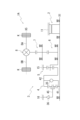
- FIG. 1 is a skeleton diagram illustrating the device.
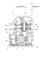
- FIG. 2 is a schematic cross-sectional view of the device.
- FIG. 3 is a schematic cross-sectional view of the device.
- FIG. 4 is a diagram explaining a gear mechanism.
- FIG. 5 is a diagram explaining a gear mechanism.
- FIG. 6 is a diagram explaining a gear mechanism.
- FIG. 7 is a diagram explaining a differential gear mechanism.
- FIG. 8 is a diagram explaining rotation of the first planetary gear mechanism.
- FIG. 9 is a diagram illustrating rotation of the second planetary gear mechanism.
- FIG. 10 is a diagram illustrating rotation of the differential gear mechanism.
- FIG. 11 is a diagram explaining a fastening table of the device.
- FIG. 12 is a diagram for explaining the engagement state of the selectable one-way clutch.
- FIG. 13 is a diagram for explaining tilting of the input shaft.
- FIG. 14 is a skeleton diagram for explaining a device according to Modification 1.
- the second element (parts, parts, etc.) connected to the first element (parts, parts, etc.), the second element (parts, parts, etc.) connected downstream of the first element (parts, parts, etc.) etc.), and a second element (part, portion, etc.) connected upstream of a first element (part, portion, etc.) means that the first element and the second element are connected so as to be able to transmit power. means The power input side is upstream, and the power output side is downstream. Also, the first element and the second element may be connected via another element (clutch, other gear mechanism, etc.).
- “Overlapping when viewed from a predetermined direction” means that a plurality of elements are arranged in a predetermined direction, and has the same meaning as “overlapping in a predetermined direction”.
- the "predetermined direction” is, for example, an axial direction, a radial direction, a gravitational direction, a vehicle running direction (vehicle forward direction, vehicle backward direction), or the like. If a drawing shows that multiple elements (parts, parts, etc.) are lined up in a predetermined direction, the description of the specification will include a sentence explaining that they overlap when viewed from a predetermined direction. You can assume that there is.
- not overlapping when viewed from a predetermined direction and “offset when viewed from a predetermined direction” mean that a plurality of elements are not aligned in a predetermined direction, and "overlapping in a predetermined direction”. It is synonymous with the descriptions of "no" and “offset in a predetermined direction”.
- the "predetermined direction” is, for example, an axial direction, a radial direction, a gravitational direction, a vehicle running direction (vehicle forward direction, vehicle backward direction), or the like. If a drawing shows that multiple elements (parts, portions, etc.) are not aligned in a predetermined direction, the description of the specification will include a sentence explaining that they do not overlap when viewed from a predetermined direction. You can assume that there is.
- the first element When viewed from a predetermined direction, the first element (part, portion, etc.) is positioned between the second element (part, portion, etc.) and the third element (part, portion, etc.)'' means that the first element can be observed to be between the second and third elements.
- the "predetermined direction" includes an axial direction, a radial direction, a gravity direction, a vehicle running direction (vehicle forward direction, vehicle backward direction), and the like.
- vehicle forward direction vehicle backward direction
- Axial direction means the axial direction of the rotating shaft of the parts that make up the device.
- Rotary direction means a direction perpendicular to the axis of rotation of the parts that make up the device.
- the parts are, for example, motors, gear mechanisms, differential gear mechanisms, and the like.
- FIG. 1 is a skeleton diagram for explaining the power transmission device 1.
- FIG. FIG. 2 is a schematic cross-sectional view of the power transmission device 1. As shown in FIG. FIG. 2 shows a cross section of the power transmission device 1 as viewed from the rear of the vehicle in a state where the power transmission device 1 is mounted on the vehicle.
- FIG. 3 is a schematic cross-sectional view of the power transmission device 1. As shown in FIG. FIG. 3 shows a cross section of the power transmission device 1 as viewed from above the vehicle in a state where the power transmission device 1 is mounted on the vehicle.
- the power transmission device 1 has a motor 2 that is a drive source, a gear mechanism 3 that transmits the output rotation of the motor 2 to a differential gear mechanism 8, and drive shafts DA and DB.
- the motor 2 is a rotating electrical machine that exhibits at least one of a motor function and a generator function.
- a gear mechanism 3, a differential gear mechanism 8, and drive shafts DA and DB are provided along the transmission path of the output rotation of the motor 2.
- the drive shafts DA and DB are oriented along an axis X5 parallel to the rotation axis X1 of the motor 2. As shown in FIG.
- the motor shaft 20 rotates around the rotation axis X1.
- the motor shaft 20 constitutes an input shaft to which the driving force of the motor 2 is input.
- the rotation of the motor shaft 20 is decelerated by the gear mechanism 3 and transmitted to the differential gear mechanism 8 .
- the output rotation transmitted to the differential gear mechanism 8 is transmitted to the left and right driving wheels K, K of the vehicle on which the power transmission device 1 is mounted via the drive shafts DA, DB.
- the gear mechanism 3 is composed of a first planetary gear mechanism 4, a second planetary gear mechanism 5, a reduction gear 6, and a counter gear 7.
- a first planetary gear mechanism 4 is connected downstream of the motor 2 .
- the second planetary gear mechanism 5 is connected downstream of the first planetary gear mechanism 4 .
- the reduction gear 6 is connected downstream of the second planetary gear mechanism 5 .
- the counter gear 7 is connected downstream of the reduction gear 6 .
- the differential gear mechanism 8 is connected downstream of the counter gear 7 of the gear mechanism 3 .
- the drive shafts DA, DB are connected downstream of the differential gear mechanism 8 .
- the drive shafts DA, DB extend from the differential gear mechanism 8 in the left-right direction of the vehicle.
- the drive shafts DA and DB are connected to left and right drive wheels (not shown), respectively.
- a reduction gear 6 is connected downstream of the second planetary gear mechanism 5 .
- the reduction gear 6 constitutes an output shaft that outputs the rotation of the second planetary gear mechanism 5 to the counter gear 7 .
- the power transmission device 1 has a housing HS that accommodates the motor 2, the gear mechanism 3 and the differential gear mechanism 8.
- the housing HS has a motor case 10 that houses the motor 2 , a gear case 13 that houses the gear mechanism 3 , and an axle case 17 that houses the differential gear mechanism 8 .
- the gear case 13 is joined to the other end side (left side in the figure) of the motor case 10 in the rotation axis X1 direction.
- the axle case 17 is arranged on the front side of the vehicle relative to the motor case 10 and the gear case 13 when the power transmission device 1 is mounted on the vehicle.
- the motor case 10 has a first case member 11 and a second case member 12 joined to one end of the first case member 11 .
- the first case member 11 has a tubular support wall portion 111 .
- One end 111 a of the support wall portion 111 is provided with a flange-shaped joint portion 112 .
- a flange-shaped joint portion 113 is provided at the other end 111 b of the support wall portion 111 .
- the support wall portion 111 is provided in a direction along the rotation axis X1.
- the motor 2 is accommodated inside the support wall portion 111 .
- a wall portion 110 extending radially inward is provided on the side of the other end 111b of the support wall portion 111 .
- the wall portion 110 is provided in a direction orthogonal to the rotation axis X1.
- An opening 110a through which the motor shaft 20 is inserted is formed in a region of the wall portion 110 intersecting with the rotation axis X1.
- the wall portion 110 is provided with a motor support portion 115 surrounding the opening 110a.
- the motor support portion 115 is provided on the surface of the wall portion 110 on the side of the motor 2 (on the right side in the figure).
- the motor support portion 115 has a tubular shape extending from the wall portion 110 toward the motor 2 side.
- the motor support portion 115 faces the end portion 21b of the rotor core 21 with a gap in the rotation axis X1 direction.
- a bearing B ⁇ b>1 is supported on the inner circumference of the motor support portion 115 .
- the outer circumference of the motor shaft 20 is supported by a motor support portion 115 via a bearing B1.
- the second case member 12 has a wall portion 120 perpendicular to the rotation axis X1 and a joint portion 122. As shown in FIG. The second case member 12 is located on the side opposite to the gear mechanism 3 (on the right side in the drawing) when viewed from the first case member 11 .
- the joint portion 122 of the second case member 12 is joined to the joint portion 112 of the first case member 11 from the rotation axis X1 direction.
- the second case member 12 and the first case member 11 are connected to each other with bolts (not shown). In this state, the second case member 12 closes the opening of the first case member 11 on the joint portion 112 side (the right side in the drawing).
- a motor support portion 125 is provided in a region of the wall portion 120 intersecting with the rotation axis X1.
- the motor support portion 125 has a tubular shape surrounding the rotation axis X1 with a space therebetween.
- the motor support portion 125 is provided on the surface of the wall portion 120 on the side of the first case member 11 (left side in the figure).
- a bearing B ⁇ b>1 is supported on the inner periphery of the motor support portion 125 .
- the outer periphery of the motor shaft 20 on the one end 20a side is supported by a motor support portion 125 via a bearing B1.
- the gear case 13 is joined to the other end (left side in the figure) of the motor case 10 from the rotation axis X1 direction.
- the gear case 13 is composed of three case members (a third case member 14, a fourth case member 15, and a fifth case member 16).
- the third case member 14, the fourth case member 15, and the fifth case member 16 are superimposed in this order in the direction away from the motor case 10 along the rotation axis X1.
- the third case member 14 has a tubular support wall portion 141 .
- a flange-shaped joining portion 142 is provided at one end 141 a of the support wall portion 141 .
- a flange-shaped joint portion 143 is provided at the other end 141b of the support wall portion 141 .
- the third case member 14 When viewed from the motor case 10, the third case member 14 is located on the side opposite to the motor 2 (left side in the figure).
- the joint portion 142 of the third case member 14 is joined to the joint portion 113 of the first case member 11 from the rotation axis X1 direction.
- the third case member 14 and the first case member 11 are connected to each other by bolts (not shown).
- the support wall portion 141 is provided along the rotation axis X ⁇ b>1 of the motor 2 .
- the reduction gear 6 and the counter gear 7 are accommodated inside the support wall portion 141 .
- a wall portion 140 extending radially inward is provided on the one end 141a side of the support wall portion 141 .
- the wall portion 140 is provided in a direction orthogonal to the rotation axis X1.
- An opening 140a through which a shaft portion 62 of the reduction gear 6 (to be described later) is inserted is provided in a region of the wall portion 140 that intersects with the rotation axis X1.
- the wall portion 140 is provided with a shaft support portion 145 surrounding the opening 140a.
- the shaft support portion 145 is provided on the surface of the wall portion 140 on the motor 2 side (the right side in the figure).
- the shaft support portion 145 has a tubular shape extending from the wall portion 140 toward the motor 2 side.
- a bearing B ⁇ b>2 is supported on the inner circumference of the shaft support portion 145 .
- the outer circumference of the shaft portion 62 of the reduction gear 6 is supported by the shaft support portion 145 via the bearing B2.
- the fourth case member 15 has a tubular support wall portion 151 .
- One end 151 a of the support wall portion 151 is provided with a flange-shaped joint portion 152 .
- a flange-shaped joint portion 153 is provided at the other end 151b of the support wall portion 151 .
- the fourth case member 15 as viewed from the third case member 14 is located on the side opposite to the motor 2 (left side in the drawing).
- the joint portion 152 of the fourth case member 15 is joined to the joint portion 143 of the third case member 14 from the rotation axis X1 direction.
- the fourth case member 15 and the third case member 14 are connected to each other with bolts (not shown).
- the support wall portion 151 is provided along the rotation axis X ⁇ b>1 of the motor 2 .
- the first planetary gear mechanism 4 and the second planetary gear mechanism 5 are accommodated inside the support wall portion 151 .
- a wall portion 150 extending radially inward is provided on the one end 151a side of the support wall portion 151 .
- the wall portion 150 is provided in a direction orthogonal to the rotation axis X1.
- An opening 150a through which a shaft portion 62 of the reduction gear 6 (to be described later) is inserted is provided in a region of the wall portion 150 that intersects with the rotation axis X1.
- a cylindrical shaft support portion 155 that surrounds the opening 150a and extends toward the third case member 14 is provided on the surface of the wall portion 150 on the third case member 14 side (right side in the figure).
- a bearing B ⁇ b>2 is supported on the inner circumference of the shaft support portion 155 .
- the outer circumference of the shaft portion 62 of the reduction gear 6 is supported by the shaft support portion 155 via the bearing B2.
- the fifth case member 16 has a cylindrical shape with a bottom.
- the fifth case member 16 includes a bottom wall portion 160 orthogonal to the rotation axis X1, a peripheral wall portion 161 surrounding the outer periphery of the bottom wall portion 160, a flange-shaped joint portion 162 provided at one end 161a of the peripheral wall portion 161, have.
- the fifth case member 16 as viewed from the fourth case member 15 is located on the opposite side (left side in the figure) of the third case member 14 .
- the joint portion 162 of the fifth case member 16 is joined to the joint portion 153 of the fourth case member 15 from the rotation axis X1 direction.
- the fifth case member 16 and the fourth case member 15 are connected to each other with bolts (not shown).
- the peripheral wall portion 161 is provided along the rotation axis X1 of the motor 2 . Inside the peripheral wall portion 161, a clutch 35, which will be described later, is accommodated.
- a wall portion 163 extending radially inward is provided on one end 161a side of the peripheral wall portion 161 .
- the wall portion 163 is provided in a direction perpendicular to the rotation axis X1.
- An opening 163a surrounding the clutch drum 352 of the clutch 35 is provided in a region of the wall portion 163 that intersects the rotation axis X1.
- a cylindrical wall portion 164 surrounding the opening 163a is provided on the surface of the wall portion 163 on the side of the fourth case member 15 (right side in the drawing).
- the tubular wall portion 164 extends toward the fourth case member 15 side.
- a columnar shaft support portion 165 is provided in a region of the bottom wall portion 160 that intersects the rotation axis X1.
- the shaft support portion 165 is provided along the rotation axis X1.
- the shaft support portion 165 extends from the surface of the bottom wall portion 160 on the side of the fourth case member 15 toward the motor 2 side.
- a support hole 166 is opened in the end face of the shaft support portion 165 in the direction of the rotation axis X1.
- the support hole 166 is recessed in the direction away from the motor 2 in the rotation axis X1 direction.
- the support hole 166 is a circular hole centered on the rotation axis X1.
- the other end 20b side of the motor shaft 20 is inserted into the support hole 166.
- a needle bearing NB is interposed between the outer circumference of the motor shaft 20 on the side of the other end 20b and the inner circumference of the support hole 166 in the radial direction of the rotation axis X1.
- the other end 20b side of the motor shaft 20 is supported by the shaft support portion 165 so as to be relatively rotatable.
- the space inside the housing HS where the motor case 10 and the gear case 13 are joined is partitioned into three by a wall portion 110 of the first case member 11 and a wall portion 150 of the fourth case member 15. be.
- the space on the side of the second case member 12 from the wall portion 110 in the direction of the rotation axis X1 is the motor chamber Sa in which the motor 2 is housed.
- a space between the wall portion 110 and the wall portion 150 in the direction of the rotation axis X1 is a first gear chamber Sb1 in which the reduction gear 6 and the counter gear 7 are accommodated.
- a space on the fifth case member 16 side from the wall portion 150 in the direction of the rotation axis X1 is a second gear chamber Sb2 that accommodates the first planetary gear mechanism 4 and the second planetary gear mechanism 5 .
- the third case member 14 is provided with an opening 141c on the front side of the vehicle.
- the third case member 14 has a flange-like joint portion 144 surrounding the opening 141c over the entire circumference.
- the axle case 17 is joined to the joint portion 144 of the third case member 14 from the vehicle front side.
- the axle case 17 has a housing portion 171 and cylindrical portions 172A and 172B.
- the housing portion 171 accommodates the differential gear mechanism 8 .
- the cylindrical portions 172A and 172B are provided at one end portion 171a and the other end portion 171b of the housing portion 171, respectively.
- the cylindrical portions 172A, 172B extend away from each other in the direction of the axis X5 and accommodate the drive shafts DA, DB, respectively.
- the housing part 171 is provided with an opening 171c on the vehicle rear side.
- the housing portion 171 has a joint portion 173 surrounding the opening 171c over the entire circumference.
- the joint portion 173 of the housing portion 171 is joined to the joint portion 144 of the third case member 14 from the direction of a straight line Lm orthogonal to the rotation axis X1 and the axis X5.
- the axle case 17 and the third case member 14 are connected to each other with bolts (not shown). Further, the internal spaces (first gear chamber Sb1, differential chamber Sb3) of the housing portion 171 and the third case member 14 communicate with each other through the openings 171c and 141c.
- Lubricating oil OL is stored in each of the differential chamber Sb3, the motor chamber Sa, the first gear chamber Sb1, and the second gear chamber Sb2.
- the oil levels of the oil OL stored in the differential chamber Sb3, the motor chamber Sa, the first gear chamber Sb1, and the second gear chamber Sb2 are substantially the same through communication holes (not shown in FIGS. 2 and 3). See Figure 10).
- the motor 2 has a motor shaft 20, a cylindrical rotor core 21 fitted onto the motor shaft 20, and a stator core 25 surrounding the outer periphery of the rotor core 21 with a gap.
- the motor shaft 20 is located inside the second case member 12 at its one end 20a side in the direction of the rotation axis X1.
- the motor shaft 20 is located inside the fifth case member 16 on the side of the other end 20b in the direction of the rotation axis X1.
- the motor shaft 20 has a wall portion 110 of the first case member 11, a wall portion 140 of the third case member 14, and a wall portion 140 of the fourth case member 15 in a region between the one end 20a side and the other end 20b side in the direction of the rotation axis X1. It penetrates the wall portion 150 in the direction of the rotation axis X1.
- a rotor core 21 is fitted onto the motor shaft 20 in a region located inside the first case member 11 .
- a reduction gear 6 is fitted onto the motor shaft 20 in a region located inside the third case member 14 .
- the second planetary gear mechanism 5 is externally fitted on the motor shaft 20 in a region of the fourth case member 15 on the side of the third case member 14 .
- the first planetary gear mechanism 4 is externally fitted on the motor shaft 20 in a region on the fifth case member 16 side inside the fourth case member 15 .
- FIG. 4 is a diagram for explaining the first planetary gear mechanism 4 that constitutes the gear mechanism 3.
- the inner pinion gear 43A and the outer pinion gear 43B are arranged in the radial direction of the rotation axis X1.
- FIG. 5 is a diagram for explaining the second planetary gear mechanism 5 that constitutes the gear mechanism 3.
- FIG. 6 is a diagram for explaining the reduction gear 6 and the counter gear 7 that constitute the gear mechanism 3.
- FIG. 7 is a diagram for explaining the differential gear mechanism 8.
- FIG. 7 is an enlarged view of a main portion of FIG. 3.
- FIG. 8A and 8B are diagrams for explaining the rotation of the first planetary gear mechanism 4.
- FIG. 8 is a schematic diagram of the AA cross section in FIG. Note that FIG. 8 shows the rotation direction in the case of the first speed. Moreover, in FIG. 8, the pinion shafts 44A and 44B are omitted. 9A and 9B are diagrams for explaining the rotation of the second planetary gear mechanism 5.
- FIG. FIG. 9 is a schematic diagram of the AA cross section in FIG. Note that the pinion shaft 54 is omitted in FIG. 10A and 10B are diagrams for explaining the rotation of the differential gear mechanism 8.
- FIG. FIG. 10 is a schematic diagram of the AA cross section in FIG. 10, only the teeth 61 and 71 of the reduction gear 6 and the counter gear 7 are shown, and only the final gear 81 of the differential gear mechanism 8 is shown in FIG.
- the first planetary gear mechanism 4 is a double pinion planetary gear mechanism. Specifically, the first planetary gear mechanism 4 has a first sun gear 41 , an inner pinion gear 43A, an outer pinion gear 43B, a first carrier 45 and a first ring gear 42 .
- the first sun gear 41 of the first planetary gear mechanism 4 is spline-fitted to the outer circumference of the motor shaft 20 . That is, the motor shaft 20 penetrates the inner circumference of the first sun gear 41 in the direction of the rotation axis X1.
- the first sun gear 41 has a toothed portion 41a having a gear formed on its outer periphery, and a cylindrical shaft portion 41b extending from the toothed portion 41a in the direction of the rotation axis X1.
- the first sun gear 41 is provided with the shaft portion 41b directed toward the fifth case member 16 side.
- a clutch 35 which is a second engagement element, is provided on the outer diameter side of the shaft portion 41b.
- a clutch hub 351 is spline-fitted to the outer circumference of the shaft portion 41b.
- the clutch hub 351 has a small-diameter tubular portion 351a, a large-diameter tubular portion 351c having a larger diameter than the small-diameter tubular portion 351a, and a disk portion 351b connecting the small-diameter tubular portion 351a and the large-diameter tubular portion 351c.
- the disk portion 351b is orthogonal to the rotation axis X1.
- the small-diameter tubular portion 351a and the large-diameter tubular portion 351c extend in directions away from the disk portion 351b in the rotation axis X1 direction.
- a drive plate 355 (inner diameter side friction plate) is spline-fitted to the outer periphery of the large diameter cylindrical portion 351c.
- the clutch hub 351 has a small-diameter cylindrical portion 351 a spline-fitted to the outer circumference of the shaft portion 41 b of the first sun gear 41 .
- the shaft portion 41b and the small-diameter cylindrical portion 351a face the shaft support portion 165 of the fifth case member 16 in the direction of the rotation axis X1.
- a thrust bearing Ba is interposed between the shaft portion 41b and the small-diameter cylindrical portion 351a and the shaft support portion 165. As shown in FIG.
- the teeth 41a of the first sun gear 41 are meshed with the inner pinion gear 43A.
- the inner pinion gear 43A meshes with the outer pinion gear 43B on the side opposite to the first sun gear 41 in the radial direction of the rotation axis X1.
- the outer pinion gear 43B meshes with the first ring gear 42 on the side opposite to the inner pinion gear 43A in the radial direction of the rotation axis X1.
- Three combinations of the inner pinion gear 43A and the outer pinion gear 43B are provided in the circumferential direction around the rotation axis X1 (see FIG. 8).
- the inner pinion gear 43A and the outer pinion gear 43B are positioned between the peripheral wall portion 421 of the first ring gear 42 and the tooth portion 41a of the first sun gear 41 in the radial direction of the rotation axis X1.
- Pinion shafts 44A and 44B pass through the inner diameter sides of the inner pinion gear 43A and the outer pinion gear 43B.
- the inner pinion gear 43A and the outer pinion gear 43B are rotatably supported by pinion shafts 44A and 44B, respectively.
- the pinion shafts 44A, 44B are oriented along axes X2a, X2b parallel to the rotation axis X1, respectively. Both ends of the pinion shaft 44A in the direction of the axis X2a are inserted into the support holes H1a and H2a of the side plate portions 451 and 452, respectively. Both ends of the pinion shaft 44B in the direction of the axis X2b are inserted into the support holes H1b and H2b of the side plate portions 451 and 452, respectively.
- the side plate portions 451 and 452 are a pair of carrier plates that constitute the first carrier 45 .
- the side plate portions 451 and 452 are provided parallel to each other in a direction perpendicular to the directions of the axes X2a and X2b.
- One side plate portion 451 located on the motor 2 side extends further to the rotation axis X1 side than the other side plate portion 452 .
- a region of the side plate portion 451 on the side of the inner peripheral surface 451c overlaps the first sun gear 41 in the direction of the rotation axis X1.
- a thrust bearing Bb (third bearing), which will be described later, is interposed between the side plate portion 451 and the first sun gear 41 in the direction of the rotation axis X1.
- a clutch drum 352 is fixed to the side plate portion 452 of the first carrier 45 .
- the clutch drum 352 has a disk-shaped bottom wall portion 352a orthogonal to the rotation axis X1, and a peripheral wall portion 352b surrounding the entire outer periphery of the bottom wall portion 352a.
- a bottom wall portion 352 a of the clutch drum 352 is fixed to the side plate portion 452 .
- the peripheral wall portion 352b has a cylindrical shape surrounding the rotation axis X1.
- the peripheral wall portion 352 b extends away from the side plate portion 452 in the direction of the rotation axis X ⁇ b>1 and surrounds the large-diameter cylindrical portion 351 c of the clutch hub 351 .
- a driven plate 356 (outer diameter side friction plate) is spline-fitted to the inner periphery of the peripheral wall portion 352 b of the clutch drum 352 .
- the piston 353 is connected to the actuator ACT.
- Actuator ACT switches contact/non-contact between drive plate 355 and driven plate 356 (arrow direction in FIG. 4) by moving piston 353 forward and backward in the direction of rotation axis X1 according to an instruction from a control device (not shown). Thereby, engagement/disengagement of the clutch 35 is switched.
- the selectable one-way clutch 36 which is the first engagement element, is provided on the outer circumference of the clutch drum 352. As shown in FIG. The selectable one-way clutch 36 is provided across the peripheral wall portion 352b of the clutch drum 352 and the tubular wall portion 164 of the fifth case member 16 in the radial direction of the rotation axis X1. 2 to 4, the selectable one-way clutch 36 is illustrated in a simplified manner.
- the selectable one-way clutch 36 has an actuator.
- the selectable one-way clutch 36 switches gear engagement by an actuator.
- the fifth case member 16 and the clutch drum 352 are switched between a relatively rotatable state and a relatively non-rotatable state via the selectable one-way clutch 36 .
- the first ring gear 42 has a ring-shaped peripheral wall portion 421 surrounding the rotation axis X1 (see FIG. 8).
- a gear is formed on the inner periphery of the peripheral wall portion 421 .
- the outer pinion gear 43B meshes with the peripheral wall portion 421 of the first ring gear 42 .
- the first ring gear 42 has a disc portion 422 extending radially inward from one end 421a of the peripheral wall portion 421 in the direction of the rotation axis X1.
- the disk portion 422 faces the side plate portion 451 with a gap in the directions of the axes X2a and X2b.
- a connecting portion 423 extending away from the peripheral wall portion 421 in the direction of the rotation axis X1 is provided in a region on the inner peripheral surface 422c side of the disc portion 422 .
- Thrust bearings Bc (first bearing) and Bd (second bearing), which will be described later, are provided on one side and the other side of the disk portion 422 in the direction of the rotation axis X1, respectively.
- the connecting portion 423 of the first ring gear 42 has a ring shape surrounding the rotation axis X1.
- the second sun gear 51 of the second planetary gear mechanism 5 is spline-fitted to the inner circumference of the connecting portion 423 .
- the second planetary gear mechanism 5 is provided at a position adjacent to the first planetary gear mechanism 4 inside the fourth case member 15 .
- the second planetary gear mechanism 5 is a single pinion planetary gear mechanism.
- the second planetary gear mechanism 5 has a second sun gear 51, a pinion gear 53, a second carrier 55, and a second ring gear 52, as shown in FIG.
- the second sun gear 51 of the second planetary gear mechanism 5 is fitted onto the motor shaft 20 .
- the motor shaft 20 passes through the inner circumference of the second sun gear 51 in the direction of the rotation axis X1.
- a needle bearing NB is interposed between the outer circumference of the motor shaft 20 and the second sun gear 51 .
- the second sun gear 51 is supported by the motor shaft 20 so as to be relatively rotatable.
- the second sun gear 51 has a toothed portion 51a having a gear formed on its outer periphery, and a cylindrical shaft portion 51b extending from the toothed portion 51a toward the first planetary gear mechanism 4 in the direction of the rotation axis X1. .
- the connecting portion 423 of the first ring gear 42 of the first planetary gear mechanism 4 is spline-fitted to the outer periphery of the shaft portion 51b of the second sun gear 51 .
- a pinion gear 53 meshes with the teeth 51 a of the second sun gear 51 .
- Three pinion gears 53 are provided in the circumferential direction around the rotation axis X1 (see FIG. 9).
- the pinion gear 53 meshes with the second ring gear 52 .
- the second ring gear 52 has a ring shape surrounding the rotation axis X1.
- the outer periphery of the second ring gear 52 is provided with a plurality of engaging teeth 521 protruding radially outward.
- the plurality of engaging teeth 521 are provided circumferentially around the rotation axis X at intervals.
- the engagement teeth 521 provided on the outer periphery of the second ring gear 52 are spline-fitted to the teeth 151 c provided on the inner periphery of the support wall portion 151 .
- a fourth case member 15 having a support wall portion 151 constitutes a second fixing element.
- a pinion shaft 54 passes through the inner diameter side of the pinion gear 53 .
- the pinion gear 53 is rotatably supported on the pinion shaft 54 .
- the pinion shaft 54 is oriented along an axis X3 parallel to the rotation axis X1. Both ends of the pinion shaft 54 in the direction of the axis X3 are inserted into the support holes H3a and H4a of the side plate portions 551 and 552, respectively.
- the side plate portions 551 and 552 are a pair of carrier plates that constitute the second carrier 55 .
- the pair of side plate portions 551 and 552 are provided parallel to each other in a direction perpendicular to the direction of the axis X3.
- One side plate portion 551 located on the motor 2 side extends further to the rotation axis X1 side than the other side plate portion 552 .
- a thrust bearing Be (fourth bearing), which will be described later, is interposed between the side plate portion 551 and the second sun gear 51 in the direction of the rotation axis X1.
- a cylindrical connecting portion 553 surrounding the rotation axis X1 is provided in the region of the side plate portion 551 on the inner peripheral surface 551c side.
- the connecting portion 553 is provided on the side surface 551a of the side plate portion 551 on the side of the motor 2 in the direction of the rotation axis X1.
- the connecting portion 553 extends toward the motor 2 in the direction of the rotation axis X1.
- the reduction gear 6 is spline-fitted to the inner circumference of the connecting portion 553 .
- Reduction gear 6 As shown in FIG. 6 , the reduction gear 6 is provided inside the third case member 14 . The reduction gear 6 is fitted onto the motor shaft 20 . A needle bearing NB is interposed between the inner circumference of the reduction gear 6 and the outer circumference of the motor shaft 20 . The reduction gear 6 is supported by the motor shaft 20 so as to be relatively rotatable.
- the reduction gear 6 has a shaft portion 62 provided in a direction along the rotation axis X1, and a tooth portion 61 having a gear formed on its outer periphery.
- the shaft portion 62 has a tubular shape surrounding the rotation axis X1.
- the shaft portion 62 is supported by the shaft support portion 145 of the third case member 14 at one end 62a side in the direction of the rotation axis X1.
- a bearing B ⁇ b>2 is interposed between the shaft portion 62 and the shaft support portion 145 .
- the shaft portion 62 is supported by the shaft support portion 155 of the fourth case member 15 at the other end 62b side in the direction of the rotation axis X1.
- a bearing B ⁇ b>2 is interposed between the shaft portion 62 and the shaft support portion 155 .
- the other end 62b of the shaft portion 62 extends into the fourth case member 15 across the wall portion 150 in the direction of the rotation axis X1.
- the connecting portion 553 of the second planetary gear mechanism 5 is spline-fitted to the outer circumference of the shaft portion 62 on the side of the other end 62 b within the fourth case member 15 .
- the tooth portion 61 is provided on the outer circumference of the shaft portion 62 .
- the tooth portion 61 and the shaft portion 62 are integrally formed.
- the tooth portion 61 is provided in a region between the portion of the shaft portion 62 supported by the shaft support portion 145 and the portion supported by the shaft support portion 155 .
- the tooth portion 61 is provided in a range that crosses a straight line Ln along the radial direction of the rotation axis X1 from the one end 62a side of the shaft portion 62 to the other end 62b side.
- the straight line Ln is a straight line passing through approximately the middle of the portions of the shaft portion 62 supported by the shaft support portions 145 and 155 .
- the tooth portion 61 of the reduction gear 6 meshes with the counter gear 7 inside the third case member 14 .
- the counter gear 7 has a shaft portion 72 provided in a direction along an axis X4 parallel to the rotation axis X1, and a tooth portion 71 having a gear formed on its outer periphery.
- the shaft portion 72 is supported by the wall portion 140 of the third case member 14 at one end 72a side (motor 2 side) in the direction of the axis X4, and is supported by the fourth case member 15 at the other end 72b side (second planetary gear mechanism 5 side). is supported by the wall 150 of the
- the one end 72 a side of the shaft portion 72 is supported by a cylindrical support portion 148 provided on the wall portion 140 .
- the support portion 148 is located on the outer diameter side of the shaft support portion 145 in the radial direction of the rotation axis X1.
- a bearing B3 is interposed between the one end 72a side of the shaft portion 72 and the support portion 148.
- the other end 72 b side of the shaft portion 72 is supported by a cylindrical support portion 157 provided on the wall portion 150 .
- the support portion 157 is located on the outer diameter side of the shaft support portion 155 in the radial direction of the rotation axis X1.
- a bearing B ⁇ b>3 is interposed between the other end 72 b side of the shaft portion 72 and the support portion 157 .
- the tooth portion 71 is provided on the outer circumference of the shaft portion 72 .
- the tooth portion 71 and the shaft portion 72 are integrally formed.
- the tooth portion 71 is provided in a region between the portion of the shaft portion 72 supported by the support portion 148 and the portion supported by the support portion 157 .
- the tooth portion 71 is provided in a range that crosses the straight line Ln from the one end 72a side of the shaft portion 72 to the other end 72b side.
- the straight line Ln passes through approximately the middle of the portions of the shaft portion 72 supported by the support portions 148 and 157 .
- the counter gear 7 meshes with the reduction gear 6 on the vehicle rear side of the axis X4 when viewed from the direction of the axis X4.
- the counter gear 7 meshes with the final gear 81 of the differential gear mechanism 8 on the front side of the vehicle with respect to the axis X4.
- the counter gear 7 meshes with the reduction gear 6 and the final gear 81 in regions below the axis X4 in the vertical line VL direction.
- the final gear 81 (input gear) of the differential gear mechanism 8 is fixed to the differential case 80 with bolts (not shown).
- the differential case 80 rotates together with the final gear 81 around the axis X5 in conjunction with the rotation of the counter gear 7 around the axis X4.
- the differential case 80 accommodates therein the shaft 82, bevel gears 83, 83, and side gears 84A, 84B.
- cylindrical support portions 801 and 802 are provided on both side portions in the direction of the axis X5 (horizontal direction of the vehicle in the figure).
- the support portions 801 and 802 are provided along the axis X5. Supports 801 and 802 extend away from shaft 82 .
- Bearings B5 and B5 are extrapolated to the support portions 801 and 802 of the differential case 80.
- the bearings B5, B5 externally fitted on the support portions 801, 802 are held by the housing portion 171 of the axle case 17. As shown in FIG.
- Drive shafts DA and DB passing through the cylindrical portions 172A and 172B of the axle case 17 are inserted into the support portions 801 and 802 from the direction of the axis X5, respectively.
- side gears 84A and 84B are spline-fitted to the outer peripheries of the tip portions of the drive shafts DA and DB.
- bevel gears 83, 83 are rotatably supported on the shaft 82 by being fitted.
- the bevel gears 83, 83 are arranged with their tooth portions opposed to each other across the axis X5.
- side gears 84A, 84B are positioned on both sides of the bevel gears 83, 83 in the direction of the axis X5.
- the side gears 84A and 84B are arranged with their tooth portions facing each other in the direction of the axis X5.
- the bevel gears 83, 83 and the side gears 84A, 84B are assembled with their teeth meshing with each other.
- a gear mechanism 3 As shown in FIG. 1, in the power transmission device 1, a gear mechanism 3, a differential gear mechanism 8, and drive shafts DA and DB are provided along the transmission path of the output rotation of the motor 2.
- the motor shaft 20 rotates together with the rotor core 21 .
- the rotation of the motor shaft 20 is input to the first sun gear 41 of the first planetary gear mechanism 4 .
- the first sun gear 41 rotates counterclockwise CCW about the rotation axis X1 (the direction of the thick arrow in the figure).
- the motor shaft 20 that is the input shaft passes through the inner circumferences of the first sun gear 41 and the second sun gear 51 .
- One end 20a side of the motor shaft 20 functions as an input portion to which the rotation of the rotor core 21 is input.
- the other end 20 b side of the motor shaft 20 functions as an output section that outputs the rotation of the rotor core 21 to the first planetary gear mechanism 4 .
- the motor shaft 20 is formed integrally with the input shaft and the output shaft.
- FIG. 11 and 12 are diagrams for explaining engagement tables showing the engagement states of the clutch 35 and the selectable one-way clutch 36 at each gear stage.
- the closed states are indicated by circles.
- the output rotation of the motor 2 is switched between first speed and second speed by switching engagement/non-engagement of the clutch 35 and the selectable one-way clutch 36 .
- the clutch 35 is released and the selectable one-way clutch 36 is engaged.
- the clutch drum 352 is fixed to the fifth case member 16 so as not to rotate relative to it.
- the first carrier 45 connected to the clutch drum 352 also becomes non-rotatable relative to the fifth case member 16 . That is, the fifth case member 16 constitutes a first fixing element.
- the selectable one-way clutch 36 may be engaged to restrict the rotation of the clutch drum 352 in the counterclockwise direction CCW (see FIG. 8) about the rotation axis X1.
- the clutch 35 is engaged and the selectable one-way clutch 36 is disengaged.
- the clutch hub 351 and the clutch drum 352 are fixed so as not to rotate relative to each other.
- the 1st sun gear 41 and the 1st carrier 45 are fixed so that relative rotation is impossible.
- the selectable one-way clutch 36 goes through an engaged state (one-way clutch state) during switching from first speed to second speed. As a result, shifting from the first gear to the second gear can be performed quickly.
- the inner pinion gear 43A that meshes with the first sun gear 41 rotates in the clockwise direction CW around the axis X2a (the direction of the thin arrow in the figure) while the revolution around the rotation axis X1 is restricted.
- the outer pinion gear 43B which meshes with the inner pinion gear 43A, rotates counterclockwise CCW about the axis X2b (in the direction of the thin arrow in the figure) while its revolution about the rotation axis X1 is restricted.
- the first ring gear 42 meshing with the outer pinion gear 43B rotates in the counterclockwise direction CCW about the rotation axis X1 (the direction of the white arrow in the figure).
- the first sun gear 41 and the first carrier 45 are fixed so as not to rotate relative to each other.
- the first sun gear 41, the first carrier 45, and the first ring gear 42 rotate integrally about the rotation axis X1. That is, in the first speed and the second speed, the rotation of the motor shaft 20 input to the first sun gear 41 is output from the first ring gear 42 without changing the rotation direction.
- the connecting portion 423 of the first ring gear 42 is spline-fitted with the second sun gear 51 of the second planetary gear mechanism 5 on the inner circumference of the connecting portion 423 . Therefore, as shown in FIG. 9, as the first ring gear 42 rotates, the second sun gear 51 of the second planetary gear mechanism 5 also rotates counterclockwise CCW about the rotation axis X1 (see FIG. 9). , thick arrow direction).
- a pinion gear 53 is in mesh with the second sun gear 51 .
- the pinion gear 53 rotates clockwise CW about the axis X3 (in the direction of the thin arrow in the figure).
- the second ring gear 52 meshing with the pinion gear 53 is fixed to the support wall portion 151 of the fourth case member 15 so as not to rotate relative to it. Therefore, the pinion gear 53 revolves in the counterclockwise direction CCW about the rotation axis X1 while rotating in the clockwise direction CW about the axis X3 (in the direction of the white arrow in the figure).
- the second carrier 55 (side plate portions 551, 552) supporting the pinion gear 53 also rotates counterclockwise CCW around the rotation axis X1.
- the connecting portion 553 of the second carrier 55 is spline-fitted with the shaft portion 62 of the reduction gear 6 on the inner circumference of the connecting portion 553 . Therefore, as shown in FIG. 10, the reduction gear 6 also rotates in the counterclockwise direction CCW about the rotation axis X1 as the second carrier 55 rotates.
- the toothed portion 61 of the reduction gear 6 meshes with the toothed portion 71 of the counter gear 7 . Therefore, the counter gear 7 rotates in the clockwise direction CW about the axis X4.
- the tooth portion 71 of the counter gear 7 also meshes with the final gear 81 of the differential gear mechanism 8 . Therefore, the final gear 81 rotates in the counterclockwise direction CCW about the axis X5.
- the counterclockwise CCW rotation of the final gear 81 about the axis X5 is transmitted to the drive shafts DA, DB via the bevel gears 83, 83 and the side gears 84A, 85B.
- Drive shafts DA and DB rotate in the same direction as final gear 81 .
- the left and right driving wheels K, K also rotate about the axis X5 by the rotational driving force transmitted from the drive shafts DA, DB. As a result, the vehicle travels forward.
- the motor shaft 20 is supported by a bearing B1 on one end 20a side in the direction of the rotation axis X1, and by a needle bearing NB on the other end 20b side.
- One end 20a side of the motor shaft 20 is press-fitted into the bearing B1.
- the other end 20b side of the motor shaft 20 is inserted into a needle bearing NB.
- the contact width W (see the enlarged view of FIG. 4) in the meshing direction of each tooth portion is uniform over the entire length in the direction of the rotation axis X1. is preferably
- the tooth portion is tilted due to the axial tilt of the motor shaft 20
- the meshing positions of the tooth portions are shifted, and the contact width in the meshing direction may not be uniform.
- the stress applied to the teeth during meshing becomes local, and the wear of the teeth progresses locally. This leads to deterioration in durability of the first planetary gear mechanism 4 and the second planetary gear mechanism 5 .
- one motor shaft 20 is passed through the inner circumferences of the first planetary gear mechanism 4 and the second planetary gear mechanism 5, so that the first planetary gear mechanism 4 and the second planetary gear mechanism follow the axial inclination.
- the mechanism 5 is tilted in the same direction, and the contact width in the meshing direction is made uniform.
- first planetary gear mechanism 4 and the second planetary gear mechanism 5 are interposed with thrust bearings Bb to Be (see FIGS. 4 and 5).
- the first planetary gear mechanism 4 is provided with a thrust bearing Bb (third bearing) between the first carrier 45 and the first sun gear 41 in the direction of the rotation axis X1.
- the thrust bearing Bb is supported by a concave portion 456 provided in the side plate portion 451 of the first carrier 45.
- the recessed portion 456 is open across a side surface 451b of the side plate portion 451 on the side of the first sun gear 41 and an inner peripheral surface 451c.
- the recess 456 has an inner peripheral surface 456a surrounding the rotation axis X1 and a bottom surface 456b orthogonal to the rotation axis X1.
- the outer race Bb1 of the thrust bearing Bb fits inside the inner peripheral surface 456a and contacts the bottom surface 456b in the direction of the rotation axis X1.
- the inner race Bb2 of the thrust bearing Bb contacts the side surface 41a1 of the tooth portion 41a of the first sun gear 41 in the direction of the rotation axis X1.
- the first planetary gear mechanism 4 is provided with a thrust bearing Bc (first bearing) between the first ring gear 42 and the first carrier 45 in the direction of the rotation axis X1.
- the disk portion 422 of the first ring gear 42 is offset toward the second planetary gear mechanism 5 in the direction of the rotation axis X1 from the outer diameter side (the peripheral wall portion 421 side) of the inner peripheral surface 422c side.
- the disc portion 422 has a recess 426 recessed toward the second planetary gear mechanism 5 from the other side surface 422b in the direction of the rotation axis X1.
- the recessed portion 426 is open across the other side surface 422b of the disk portion 422 and the inner peripheral surface 422c.
- the thrust bearing Bc is supported by the recess 426.
- the recess 426 has an inner peripheral surface 426a surrounding the rotation axis X1 and a bottom surface 426b orthogonal to the rotation axis X1.
- the outer race Bc1 of the thrust bearing Bc is fitted in the inner peripheral surface 426a and is in contact with the bottom surface 426b in the direction of the rotation axis X1.
- a side surface 451a of the side plate portion 451 on the side opposite to the first sun gear 41 contacts the inner race Bc2 of the thrust bearing Bc in the direction of the rotation axis X1.
- a thrust bearing Bd (second bearing ) As shown in FIG. 4, in the first planetary gear mechanism 4, a thrust bearing Bd (second bearing ) is provided. As shown in the enlarged view of FIG. 4, the disc portion 422 has a convex portion 425 that protrudes toward the second planetary gear mechanism 5 from one side surface 422a in the direction of the rotation axis X1. The convex portion 425 is provided across one side surface 422a of the disk portion 422 and the inner peripheral surface 422c.
- the thrust bearing Bd is fitted on the convex portion 425 .
- the inner race Bd2 of the thrust bearing Bd is fitted onto the outer peripheral surface 425a of the convex portion 425 and is in contact with one side surface 422a of the disk portion 422.
- a surface 552a facing the disk portion 422 of the side plate portion 552 of the second carrier 55 contacts the outer race Bd1 of the thrust bearing Bd in the direction of the rotation axis X1.
- the radius R1 of the inner peripheral surface 426a of the concave portion 426 is smaller than the radius R2 of the outer peripheral surface 425a of the convex portion 425 (R1 ⁇ R2).
- An outer race Bc1 of the thrust bearing Bc is fitted into the inner peripheral surface 426a of the recess 426.
- An inner race Bd ⁇ b>2 of the thrust bearing Bd is fitted onto the outer peripheral surface 425 a of the convex portion 425 .
- the thrust bearings Bc and Bd have a positional relationship in which they do not overlap each other. That is, the thrust bearing Bc (first bearing) and the thrust bearing Bd (second bearing) are arranged offset from each other in the radial direction of the rotating shaft X1 (the radial direction of the input shaft).
- the second planetary gear mechanism 5 is provided with a thrust bearing Be (fourth bearing) between the second sun gear 51 and the second carrier 55 in the direction of the rotation axis X1.
- the thrust bearing Be is supported by a concave portion 556 provided in the side plate portion 551 of the second carrier 55.
- the recessed portion 556 is open across the side surface 551b of the side plate portion 551 on the side of the second sun gear 51 and the inner peripheral surface 551c.
- the recess 556 has an inner peripheral surface 556a surrounding the rotation axis X1 and a bottom surface 556b perpendicular to the rotation axis X1.
- the outer race Be1 of the thrust bearing Be is fitted into the inner peripheral surface 556a and is in contact with the bottom surface 556b in the direction of the rotation axis X1.
- the inner race Be2 of the thrust bearing Be is in contact with the side surface 51a1 of the tooth portion 51a of the second sun gear 51 in the direction of the rotation axis X1.
- 13A and 13B are diagrams for explaining the axial tilt of the motor shaft 20.
- FIG. 13 the inclinations of the motor shaft 20, the first planetary gear mechanism 4, and the second planetary gear mechanism 5 due to the axial inclination are exaggerated.
- the motor shaft 20 may rotate around the rotation axis X1′ inclined by an angle ⁇ from the rotation axis X1.
- a first sun gear 41 of the first planetary gear mechanism 4 is spline-fitted to the outer circumference of the motor shaft 20 .
- a second sun gear 51 of the second planetary gear mechanism 5 is provided on the outer circumference of the motor shaft 20 .
- the first sun gear 41 and the second sun gear 51 supported by the motor shaft 20 also tilt along the rotation axis X1'.
- the tooth surface 41a2 of the tooth portion 41a is oriented along a straight line Lp1 parallel to the rotation axis X1'.
- the tooth surface 51a2 of the tooth portion 51a and the tooth surface 51b2 of the shaft portion 51b are oriented along straight lines Lp2 and Lp3 directions parallel to the rotation axis X1', respectively.
- the connecting portion 423 of the first ring gear 42 is spline-fitted to the outer circumference of the shaft portion 51b of the second sun gear 51. Therefore, the connecting portion 423 is inclined along the straight line Lp2.
- the disk portion 422 of the first ring gear 42 connected to the connecting portion 423 is tilted in a direction orthogonal to the straight line Lp2.
- the peripheral wall portion 421 connected to the disk portion 422 has a tooth surface 421b oriented along a straight line Lp4 parallel to the straight line Lp2. In this state, the peripheral wall portion 421 of the first ring gear 42 rotates around the rotation axis X1'.
- the outer pinion gear 43B and the inner pinion gear 43A are positioned between the first sun gear 41 and the first ring gear 42 in the radial direction of the rotation axis X1'.
- the straight lines Lp1, Lp4 and the rotation axis X1' are parallel to each other.
- the inner pinion gear 43A meshes with the teeth 41a of the first sun gear 41.
- the inner pinion gear 43A follows the first sun gear 41 and inclines along the direction of the straight line Lp1.
- the outer pinion gear 43B meshes with the peripheral wall portion 421 of the first ring gear 42 .
- the outer pinion gear 43B follows the first ring gear 42 and tilts along the direction of the straight line Lp4.
- the meshing portions of the inner pinion gear 43A and the outer pinion gear 43B are oriented along a straight line Lp5 parallel to the straight lines Lp1 and Lp4.
- the axes X2a', X2b' of the pinion shafts 44A, 44B are also parallel to the rotation axis X1'.
- the pair of side plate portions 451 and 452 that support the pinion shafts 44A and 44B are not fixed to the first sun gear 41 and the first ring gear 42, so they tilt in a direction perpendicular to the axes X2a' and X2b'. That is, the first carrier 45 having the side plate portions 451 and 452 inclines in the same direction as the first sun gear 41 , the first ring gear 42 and the first carrier 45 . Therefore, the first planetary gear mechanism 4 tilts in the same direction as the motor shaft 20 as a whole.
- a thrust bearing Bc is interposed between the disc portion 422 of the first ring gear 42 and the side plate portion 451 of the first carrier 45 .
- the thrust bearing Bc when the outer diameter side of the disc portion 422 tilts away from the second planetary gear mechanism 5 (in the direction of arrow E in the figure), the thrust bearing Bc also tilts in the same direction.
- the tilted thrust bearing Bc presses the side plate portion 451 of the first carrier 45 (direction of arrow A in the figure).
- the first carrier 45 also generates a moment to rotate in the direction in which the outer diameter side is separated from the second planetary gear mechanism 5 (direction of arrow E in the figure).
- the pinion gear 53 meshes with the tooth portion 51 a of the second sun gear 51 .
- a pinion gear 53 is supported by a second carrier 55 via a pinion shaft 54 .
- a thrust bearing Bd is interposed between the side plate portion 552 of the second carrier 55 and the disc portion 422 of the first ring gear 42 .
- the thrust bearing Bd when the outer diameter side of the disc portion 422 tilts away from the second planetary gear mechanism 5 (in the direction of arrow E in the drawing), the thrust bearing Bd also tilts in the same direction.
- the tilted thrust bearing Bd presses the side plate portion 552 of the second carrier 55 (in the direction of arrow B in the figure). Then, a moment is generated in the second carrier 55 so that the outer diameter side is tilted toward the first planetary gear mechanism 4 (direction of arrow F in the drawing).
- the second carrier 55 This promotes the side plate portion 552 of the second carrier 55 to tilt in the same direction in conjunction with the first ring gear 42 .
- the pinion shaft 54 and the side plate portion 551 are also inclined in the same direction. That is, the second carrier 55 tilts in accordance with the tilt of the first ring gear 42 , so that the second carrier 55 finally tilts in the same direction as the second sun gear 51 . Since the second ring gear 52 is provided on the fourth case member 15 (see FIG. 5), it maintains its orientation along the rotation axis X1.
- the axis X3' of the pinion shaft 54 is parallel to the rotation axis X1'.
- the pinion gear 53 supported by the pinion shaft 54 meshes with the tooth portion 51a of the second sun gear 51 along the direction of the straight line Lp3.
- the inclination of the first sun gear 41 of the first planetary gear mechanism 4 interlocks with the inclination of the second sun gear 51 of the second planetary gear mechanism 5 via the motor shaft 20 .
- the inclination of the first ring gear 42 of the first planetary gear mechanism 4 interlocks with the inclination of the second sun gear 51 of the second planetary gear mechanism 5 via the connecting portion 423 .
- the first carrier 45 of the first planetary gear mechanism 4 does not have a configuration to be connected to the second planetary gear mechanism 5 , it is difficult to interlock with the inclination of the second planetary gear mechanism 5 .
- a thrust bearing Bb is interposed between the tooth portion 41 a of the first sun gear 41 and the side plate portion 451 of the first carrier 45 .
- the thrust bearing Bb transmits the pressing force received from the first sun gear 41 to the side plate portion 451 of the first carrier 45 (direction of arrow C in the figure).
- a moment is generated in the first carrier 45 to rotate the outer diameter side away from the second planetary gear mechanism 5 (direction of arrow E in the figure). This facilitates tilting of the first carrier 45 in the same direction in conjunction with the first sun gear 41 .
- first sun gear 41, the first ring gear 42, and the first carrier 45 which are the three members in the first planetary gear mechanism 4, are interlocked and tilt in the same direction. Positional deviation can be reduced, and the durability of the first planetary gear mechanism 4 can be improved.
- a thrust bearing Be is interposed between the tooth portion 51 a of the second sun gear 51 and the side plate portion 551 of the second carrier 55 .
- the thrust bearing Be transmits the pressing force received from the second sun gear 51 to the side plate portion 551 of the second carrier 55 (direction of arrow D in the figure). Then, a moment is generated in the second carrier 55 so that the outer diameter side is tilted toward the first planetary gear mechanism 4 (direction of arrow F in the drawing).
- the power transmission device 1 is a motor shaft 20 (input shaft) to which driving force is input; a first planetary gear mechanism 4 arranged downstream of the motor shaft 20; a second planetary gear mechanism 5 arranged downstream of the first planetary gear mechanism 4; and a reduction gear 6 (output shaft) arranged downstream of the second planetary gear mechanism 5 .
- the first planetary gear mechanism 4 has a first sun gear 41 .
- the first planetary gear mechanism 4 has a first carrier 45 connected to the fifth case member 16 (first fixed element) via the selectable one-way clutch 36 (first engaging element).
- the first planetary gear mechanism 4 has a first ring gear 42 .
- the second planetary gear mechanism 5 has a second sun gear 51 connected to the first ring gear 42 .
- the second planetary gear mechanism 5 has a second carrier 55 connected with the reduction gear 6 .
- the second planetary gear mechanism 5 has a second ring gear 52 connected to the fourth case member 15 (second fixed element).
- the first carrier 45 which is one element among the first sun gear 41, the first carrier 45, and the first ring gear 42, is connected to the first sun gear 41 and the first carrier 45 via the clutch 35 (second engagement element). It is connected to the first sun gear 41 which is another element of the first ring gear 42 .
- the first sun gear 41 is connected to the motor shaft 20 by spline fitting.
- the second sun gear 51 is supported by the motor shaft 20 via needle bearings NB.
- the first planetary gear mechanism 4 is a double pinion planetary gear mechanism.
- the second planetary gear mechanism 5 is a single pinion planetary gear mechanism.
- the power transmission device 1 With this configuration, it is possible to provide the power transmission device 1 with improved layout. For example, when inputting the output rotation of the motor 2 to the first carrier 45 or the first ring gear 42 of the first planetary gear mechanism 4, a portion extending to the motor shaft 20 and the first carrier 45 or the first ring gear 42 is provided. need arises. The portion is arranged to cross the side of the first sun gear 41 (the space overlapping the first sun gear 41 in the direction of the rotation axis X). The axial dimension of the power transmission device 1 as a whole increases by the amount of space provided for arranging this portion.
- first sun gear 41 and the second sun gear 51 are used for both rotational inputs to the first planetary gear mechanism 4 and the second planetary gear mechanism 5, and the second sun gear 51 is supported by the motor shaft 20.
- the first sun gear 41 and the second sun gear 51 are supported by the motor shaft 20.
- the first sun gear 41 is spline-fitted to the motor shaft 20 and is easily affected by the inclination of the motor shaft 20 .
- the second sun gear 51 is also supported by the motor shaft 20 via needle bearings NB and is easily affected by the inclination of the motor shaft 20 .
- Second sun gear 51 is connected to first ring gear 42 . Therefore, the first ring gear 42 tends to tilt in the same direction as the second sun gear 51 .
- the remaining one element, the first carrier 45 also tends to tilt in the same direction. That is, all the three elements (the first sun gear 41, the first ring gear 42, and the first carrier 45) of the first planetary gear mechanism 4 tend to tilt in the same direction. Therefore, in the first planetary gear mechanism 4 , it is possible to reduce the deviation of the meshing positions of the gears due to the difference in the tilting direction of the gears, which contributes to the improvement of the durability of the first planetary gear mechanism 4 .
- the selectable one-way clutch 36 (first engagement element) connected to the fifth case member 16 (first fixed element) is arranged in the first position in order to secure layout flexibility. It is connected to the carrier 45 (see FIG. 2).
- the first carrier 45 has a smaller diameter than the first ring gear 42 .
- the selectable one-way clutch 36 is arranged so as to surround the outer circumference of the first ring gear 42 .
- the selectable one-way clutch 36 becomes radially larger than when it is connected to the first carrier 45 . Then, the stirring resistance due to the rotation of the first planetary gear mechanism 4 increases.
- the selectable one-way clutch 36 by connecting the selectable one-way clutch 36 to the first carrier 45, it can be placed closer to the motor shaft 20 (the shaft center side of the rotating shaft). That is, even if the first planetary gear mechanism 4 rotates, an increase in stirring resistance can be reduced.
- by shifting the position of the selectable one-way clutch 36 to the inner diameter side of the rotation shaft X1 it becomes possible to take the option of reducing the stirring resistance of the first planetary gear mechanism 4.
- the freedom of layout of the selectable one-way clutch 36 is ensured.
- the selectable one-way clutch 36 since the selectable one-way clutch 36 is engaged by meshing gears, it does not generate drag resistance unlike the case where a band brake or a multi-plate clutch is used as the first engagement element, for example, so that friction can be reduced. In addition, since the selectable one-way clutch 36 can be set to an engaged state (one-way clutch state), the shift speed is faster and the shift controllability is improved as compared with, for example, a band brake.
- the output of the first planetary gear mechanism 4 becomes the first ring gear 42 .
- the type of the first planetary gear mechanism 4 is a single pinion type, it is necessary to switch the rotation direction of the motor 2 between forward rotation and reverse rotation when switching between first speed and second speed. Therefore, by adopting a double pinion type for the first planetary gear mechanism 4, the rotation direction of the motor 2 can be aligned in the same rotation direction (for example, forward rotation) even when switching between the first speed and the second speed. will be able to
- the input of the second planetary gear mechanism 5 is the second sun gear 51 . Therefore, the output can be selected from both the second carrier 55 and the second ring gear 52 .
- the second carrier 55 is fixed.
- the axial dimension of the power transmission device 1 as a whole increases by the amount of space provided for arranging this portion.
- the second planetary gear mechanism 5 is the input of the second sun gear 51 and the output of the second carrier 55, when comparing the single pinion type planetary gear mechanism and the double pinion type planetary gear mechanism, the single pinion type planetary gear mechanism decelerates. It is easy to take a large ratio. Therefore, the second planetary gear mechanism 5 is preferably a single pinion planetary gear mechanism.
- one aspect of the present invention is based on the premise that both the first planetary gear mechanism 4 and the second planetary gear mechanism 5 are sun gear inputs, and the connection relationship and the planetary gears thereof in order to solve various problems. It can be said that the selection of the type of mechanism is a carefully designed aspect.
- the first fixing element is the fifth case member 16
- the second fixing element is the fourth case member 15
- the fifth case member 16 and the fourth case member 15 are separate bodies.
- the case is exemplified, it is not limited to this aspect.
- the first fixing element and the second fixing element may be integrally formed.
- a thrust bearing Bc (first bearing) is arranged between the first ring gear 42 and the first carrier 45 in the direction of the rotation axis X1 of the motor shaft 20 .
- the first ring gear 42 tilts in conjunction with the second sun gear 51 .
- the second sun gear 51 tilts in conjunction with the first sun gear 41 . That is, the first ring gear 42, the second sun gear 51, and the first sun gear 41 tilt together. Therefore, by configuring as described above and providing the thrust bearing Bc between the first ring gear 42 and the first carrier 45 , the first carrier 45 tilts in conjunction with the first ring gear 42 . Therefore, the first sun gear 41, the first ring gear 42, and the first carrier 45, which are three members in the first planetary gear mechanism 4, interlock with the inclination of the rotation axis X1 so as to incline to the same side. As a result, it is possible to reduce the deviation of the meshing position in the first planetary gear mechanism 4 and improve the durability of the first planetary gear mechanism 4 .
- a thrust bearing Bd (second bearing) is arranged between the first ring gear 42 and the second carrier 55 in the direction of the rotation axis X1 of the motor shaft 20 .
- the first ring gear 42 tilts in conjunction with the second sun gear 51 .
- the second sun gear 51 tilts in conjunction with the first sun gear 41 . That is, the first sun gear 41, the first ring gear 42, and the second sun gear 51 tilt together. Therefore, by configuring as described above and providing the thrust bearing Bd between the first ring gear 42 and the second carrier 55 , the second carrier 55 tilts in conjunction with the first ring gear 42 . Therefore, the second carrier 55 tilts in conjunction with the second sun gear 51 . That is, the second sun gear 51 and the second carrier 55, which are two members in the second planetary gear mechanism 5, interlock and tilt in the same direction. As a result, it is possible to reduce the deviation of the meshing position in the second planetary gear mechanism 5 and improve the durability of the second planetary gear mechanism 5 .
- a thrust bearing Bc is arranged between the first ring gear 42 and the first carrier 45 in the direction of the rotation axis X1 of the motor shaft 20 .
- a thrust bearing Bd is arranged between the first ring gear 42 and the second carrier 55 in the direction of the rotation axis X1 of the motor shaft 20 .
- the thrust bearing Bc and the thrust bearing Bd are arranged offset from each other in the radial direction of the rotation axis X1 of the motor shaft 20 .
- the pair of thrust bearings Bc and Bd are overlapped in the rotation axis X1 direction. It is also possible. However, from the viewpoint of ensuring the rigidity and strength of the disk portion 422, it is conceivable to ensure the thickness of the disk portion 422 by a predetermined amount. As a result, the axial length of the entire power transmission device 1 is increased.
- a thrust bearing Bb (third bearing) is arranged between the first carrier 45 and the first sun gear 41 in the direction of the rotation axis X1 of the motor shaft 20 .
- the first ring gear 42 tilts in conjunction with the second sun gear 51 .
- the second sun gear 51 tilts in conjunction with the first sun gear 41 . That is, the first sun gear 41, the first ring gear 42, and the second sun gear 51 tilt together.
- the first carrier 45 of the first planetary gear mechanism 4 does not have a structure to be connected to the second planetary gear mechanism 5 , it is difficult to interlock with the inclination of the second planetary gear mechanism 5 . Therefore, by configuring as described above and providing the thrust bearing Bb between the first carrier 45 and the first sun gear 41 , the first carrier 45 tilts in conjunction with the first sun gear 41 .
- the first sun gear 41, the first ring gear 42, and the first carrier 45 which are three members in the first planetary gear mechanism 4, interlock and tilt in the same direction. As a result, it is possible to reduce the deviation of the meshing position in the first planetary gear mechanism 4 and improve the durability of the first planetary gear mechanism 4 .
- a thrust bearing Be (fourth bearing) is arranged between the second sun gear 51 and the second carrier 55 in the direction of the rotation axis X1 of the motor shaft 20 .
- the second carrier 55 tilts in conjunction with the second sun gear 51 . Therefore, the second sun gear 51 and the second carrier 55, which are two members in the second planetary gear mechanism, interlock and tilt in the same direction. As a result, it is possible to reduce the deviation of the meshing position in the second planetary gear mechanism 5 and improve the durability of the second planetary gear mechanism 5 .
- the power transmission device 1 has a motor 2 (power source) that supplies driving force to the motor shaft 20 .
- the second planetary gear mechanism 5 is arranged between the motor 2 and the first planetary gear mechanism 4 in the rotation axis X1 direction of the motor shaft 20 .
- the output rotation of the motor 2 is input to the one end 20a side of the motor shaft 20 provided with the rotor core 21, and output to the other end 20b provided with the first planetary gear mechanism 4.
- the output rotation output to the first planetary gear mechanism 4 is transmitted to the second planetary gear mechanism 5 arranged between the motor 2 and the first planetary gear mechanism 4 .
- the output rotation transmitted to the second planetary gear mechanism 5 is transmitted from the counter gear 7 to the differential gear mechanism 8 via the reduction gear 6 arranged between the motor 2 and the second planetary gear mechanism 5 .
- the transmission path of the output rotation in the power transmission device 1 goes from the one end 20a side of the motor shaft 20 to the other end 20b side, then turns back to the one end 20a side, and extends between the one end 20a and the other end 20b of the motor shaft 20. is output from the area of This facilitates disposing the differential gear mechanism 8 that meshes with the counter gear 7 so as to be close to the power source of the motor 2 in the direction of the rotation axis X1. As a result, it is possible to reduce the increase in the size of the power transmission device 1 in the direction of the rotation axis X1.
- the motor shaft 20 passes through the inner circumferences of the first sun gear 41 and the second sun gear 51 and is formed integrally with the output shaft of the motor 2 .
- the motor shaft is configured by connecting a plurality of shaft members.
- it has a first shaft member connected to the rotor core 21 and a second shaft member connected to the first sun gear 41 of the first planetary gear mechanism 4, and the first shaft member and the second shaft member are connected to each other.
- connecting a plurality of shaft members together increases the manufacturing cost because the number of parts increases and a process for aligning the shaft members is required. Since multiple members are joined together, the shaft tends to swing. Therefore, by configuring as described above and performing input of the rotation of the rotor core 21 and output of the rotation to the first planetary gear mechanism 4 with one motor shaft 20, the shaft support structure can be reduced. It becomes possible. As a result, it is possible to reduce the size and weight and the manufacturing cost by reducing the number of parts.
- the first carrier 45 which is one element among the first sun gear 41, the first carrier 45, and the first ring gear 42, is connected to the first sun gear 41 via the clutch 35 (second engagement element).
- the case where the 1st carrier 45 and the 1st sun gear 41 which are other one elements of the 1st ring gears 42 are connected was illustrated (refer FIG. 1). However, it is not limited to this aspect. For example, it may be as follows.
- FIG. 14 is a skeleton diagram for explaining a power transmission device 1A according to Modification 1.
- the first sun gear 41 which is one element among the first sun gear 41, the first carrier 45, and the first ring gear 42, is connected to the clutch 35 (the first 2 fastening elements), the first sun gear 41, the first carrier 45, and the first ring gear 42, which is another element of the first ring gear 42, are connected.
- FIG. 15 is a skeleton diagram for explaining a power transmission device 1B according to Modification 2.
- the first carrier 45 which is one element among the first sun gear 41, the first carrier 45, and the first ring gear 42, is connected to the clutch 35 (first 2 fastening elements), the first sun gear 41, the first carrier 45, and the first ring gear 42, which is another element of the first ring gear 42, are connected.
- a power transmission device for a vehicle was illustrated, but it is not limited to this aspect. Any device that includes a planetary gear mechanism can be applied to a device other than a vehicle.
Landscapes
- Engineering & Computer Science (AREA)
- General Engineering & Computer Science (AREA)
- Mechanical Engineering (AREA)
- Structure Of Transmissions (AREA)
- Retarders (AREA)
Priority Applications (1)
| Application Number | Priority Date | Filing Date | Title |
|---|---|---|---|
| JP2024504367A JP7551272B2 (ja) | 2022-03-01 | 2022-11-29 | 装置 |
Applications Claiming Priority (2)
| Application Number | Priority Date | Filing Date | Title |
|---|---|---|---|
| JP2022-030524 | 2022-03-01 | ||
| JP2022030524 | 2022-03-01 |
Publications (1)
| Publication Number | Publication Date |
|---|---|
| WO2023166802A1 true WO2023166802A1 (ja) | 2023-09-07 |
Family
ID=87883599
Family Applications (1)
| Application Number | Title | Priority Date | Filing Date |
|---|---|---|---|
| PCT/JP2022/044061 Ceased WO2023166802A1 (ja) | 2022-03-01 | 2022-11-29 | 装置 |
Country Status (2)
| Country | Link |
|---|---|
| JP (1) | JP7551272B2 (https=) |
| WO (1) | WO2023166802A1 (https=) |
Citations (3)
| Publication number | Priority date | Publication date | Assignee | Title |
|---|---|---|---|---|
| JP2009061923A (ja) * | 2007-09-06 | 2009-03-26 | Toyota Motor Corp | ハイブリッド車の駆動装置 |
| WO2020105636A1 (ja) * | 2018-11-19 | 2020-05-28 | アイシン・エィ・ダブリュ株式会社 | 車両用駆動装置 |
| WO2020183789A1 (ja) * | 2019-03-10 | 2020-09-17 | ジヤトコ株式会社 | 動力伝達装置 |
Family Cites Families (3)
| Publication number | Priority date | Publication date | Assignee | Title |
|---|---|---|---|---|
| JP4667078B2 (ja) * | 2005-03-07 | 2011-04-06 | トヨタ自動車株式会社 | 車輌用駆動装置 |
| JP2006300255A (ja) * | 2005-04-22 | 2006-11-02 | Nissan Motor Co Ltd | 多重軸潤滑装置 |
| DE102019207785A1 (de) * | 2019-05-28 | 2020-12-03 | Zf Friedrichshafen Ag | Elektrischer Antrieb für ein Fahrzeug |
-
2022
- 2022-11-29 JP JP2024504367A patent/JP7551272B2/ja active Active
- 2022-11-29 WO PCT/JP2022/044061 patent/WO2023166802A1/ja not_active Ceased
Patent Citations (3)
| Publication number | Priority date | Publication date | Assignee | Title |
|---|---|---|---|---|
| JP2009061923A (ja) * | 2007-09-06 | 2009-03-26 | Toyota Motor Corp | ハイブリッド車の駆動装置 |
| WO2020105636A1 (ja) * | 2018-11-19 | 2020-05-28 | アイシン・エィ・ダブリュ株式会社 | 車両用駆動装置 |
| WO2020183789A1 (ja) * | 2019-03-10 | 2020-09-17 | ジヤトコ株式会社 | 動力伝達装置 |
Also Published As
| Publication number | Publication date |
|---|---|
| JP7551272B2 (ja) | 2024-09-17 |
| JPWO2023166802A1 (https=) | 2023-09-07 |
Similar Documents
| Publication | Publication Date | Title |
|---|---|---|
| US20130324352A1 (en) | Carrier | |
| JP7134585B2 (ja) | 動力伝達装置 | |
| KR20090034869A (ko) | 감속 기어 변속기 | |
| US20250242675A1 (en) | Drive device for vehicle | |
| JP7263401B2 (ja) | 動力伝達装置 | |
| JP7529928B2 (ja) | 左右輪駆動装置 | |
| JP7423881B2 (ja) | 動力伝達装置 | |
| WO2021039966A1 (ja) | 車両用駆動装置 | |
| WO2020161979A1 (ja) | 動力伝達装置 | |
| JP4151300B2 (ja) | 無段変速装置 | |
| JP5373748B2 (ja) | 自動変速機 | |
| JP7694685B2 (ja) | 車両用駆動装置 | |
| JP7551272B2 (ja) | 装置 | |
| JP7573932B2 (ja) | 動力伝達装置 | |
| JP7487438B2 (ja) | 動力伝達装置 | |
| JP7337474B2 (ja) | 動力伝達装置 | |
| WO2018181557A1 (ja) | 車両用駆動装置 | |
| JP7829366B2 (ja) | プラネタリギヤ機構 | |
| WO2015159868A1 (ja) | トロイダル型無段変速機 | |
| JP5373735B2 (ja) | 自動変速機 | |
| JP7350450B2 (ja) | 動力伝達装置 | |
| JP7118578B2 (ja) | 動力伝達装置 | |
| JP7350452B2 (ja) | 動力伝達装置 | |
| JP7371310B2 (ja) | 動力伝達装置 | |
| JP7495991B2 (ja) | 車両用駆動装置 |
Legal Events
| Date | Code | Title | Description |
|---|---|---|---|
| 121 | Ep: the epo has been informed by wipo that ep was designated in this application |
Ref document number: 22929944 Country of ref document: EP Kind code of ref document: A1 |
|
| WWE | Wipo information: entry into national phase |
Ref document number: 2024504367 Country of ref document: JP |
|
| NENP | Non-entry into the national phase |
Ref country code: DE |
|
| 122 | Ep: pct application non-entry in european phase |
Ref document number: 22929944 Country of ref document: EP Kind code of ref document: A1 |