WO2023166590A1 - 光増幅器及び光増幅方法 - Google Patents
光増幅器及び光増幅方法 Download PDFInfo
- Publication number
- WO2023166590A1 WO2023166590A1 PCT/JP2022/008781 JP2022008781W WO2023166590A1 WO 2023166590 A1 WO2023166590 A1 WO 2023166590A1 JP 2022008781 W JP2022008781 W JP 2022008781W WO 2023166590 A1 WO2023166590 A1 WO 2023166590A1
- Authority
- WO
- WIPO (PCT)
- Prior art keywords
- optical
- amplifier
- amplification
- signal
- optical parametric
- Prior art date
Links
Images


Classifications
-
- H—ELECTRICITY
- H04—ELECTRIC COMMUNICATION TECHNIQUE
- H04B—TRANSMISSION
- H04B10/00—Transmission systems employing electromagnetic waves other than radio-waves, e.g. infrared, visible or ultraviolet light, or employing corpuscular radiation, e.g. quantum communication
- H04B10/29—Repeaters
- H04B10/291—Repeaters in which processing or amplification is carried out without conversion of the main signal from optical form
Definitions
- the present invention relates to an optical amplifier and an optical amplification method.
- Broadband transmission systems for conventional optical amplification and transmission systems have been achieved by using rare-earth-doped fiber amplifiers (EDFA (Erbium Doped Fiber Amplifier), BDFA (Bithmus Doped Fiber Amplifier), etc.) and semiconductor optical amplifiers (SOA: (Semiconductor Optical Amplifier), and in some cases, it is realized in combination with backward-pumping distributed Raman amplification that can control the amplification band with the pumping light wavelength that uses the transmission line itself as the amplification medium.
- EDFA Erbium Doped Fiber Amplifier
- BDFA Bithmus Doped Fiber Amplifier
- SOA semiconductor optical amplifier
- Rare-earth-doped optical fiber amplifiers and semiconductor optical amplifiers are expected to increase or decrease the number of wavelengths because there is concern that rapid fluctuations in input optical signal power will cause optical surges, degrading signal quality and damaging optical components. There was a problem in applying it to a future optical network that utilizes abundant wavelength resources.
- optical parametric amplification which is capable of amplifying polarization multiplexed signals and has excellent broadband characteristics and high-speed responsiveness, to optical amplifier repeaters has been studied (see, for example, Non-Patent Document 2).
- the optical signal is not distorted in the operating region where the gain is saturated.
- the gain fluctuates according to the magnitude of the amplitude component of the signal, causing distortion in the signal. Therefore, it is difficult for an optical parametric amplifier to achieve both high gain and high output.
- the signal-to-noise ratio is improved by increasing the input power to the transmission line fiber, the signal will be distorted due to gain saturation in the optical parametric amplifier. Poor signal quality. Therefore, there is a problem that the signal quality after amplification is limited in the wide amplification band covered by the optical parametric amplifier.
- One aspect of the present invention is an optical amplifier that optically amplifies and repeats an optical signal transmitted through an optical fiber transmission line, comprising: an optical parametric amplifier that performs optical parametric amplification on an input optical signal; and the optical fiber transmission line.
- a Raman amplifier for controlling a gain so as to shift the optimum input optical power in the optical parametric amplifier to a region where the output of the optical parametric amplifier is linearly amplified.
- One aspect of the present invention is an optical amplification method in an optical amplifier that optically amplifies and repeats an optical signal transmitted through an optical fiber transmission line, wherein an optical parametric amplifier performs optical parametric amplification on an input optical signal,
- the gain is controlled such that the optimum input optical power in the optical fiber transmission line is shifted to a region where the output of the optical parametric amplifier is linearly amplified.
- optical amplifying repeaters it is possible to perform broadband and high-quality optical amplifying repeaters in optical amplifying repeaters using optical parametric amplification.
- FIG. 1 is a diagram showing a configuration example of an optical transmission system according to the present invention
- FIG. 1 is a diagram for explaining a basic configuration example of an optical amplifier according to the present invention
- FIG. FIG. 4 is a diagram for explaining the effect of combining optical parametric amplification and forward-pumped Raman amplification
- FIG. 4 is a diagram for explaining the effect of combining optical parametric amplification and forward-pumped Raman amplification
- 1 is a diagram illustrating a configuration example of an optical amplifier according to a first embodiment
- FIG. 4 is a flow chart showing the flow of processing performed by the optical amplifier in the first embodiment
- FIG. 10 is a diagram illustrating a configuration example of an optical amplifier according to a second embodiment
- FIG. 9 is a flow chart showing the flow of processing performed by the optical amplifier in the second embodiment; It is a figure for demonstrating the effect in 1st Embodiment and 2nd Embodiment.
- FIG. 12 is a diagram illustrating a configuration example of an optical amplifier according to a third embodiment; FIG.
- FIG. 1 is a diagram showing a configuration example of an optical transmission system 100 according to the present invention.
- the optical transmission system 100 includes a plurality of optical transmitters 10-1 to 10-N (N is an integer equal to or greater than 2), an optical multiplexer/demultiplexer 20, an optical amplifying repeater transmission line 30, an optical multiplexer/demultiplexer 40, A plurality of optical receivers 50-1 to 50-N are provided.
- the optical amplifying repeater transmission line 30 is configured using one or more optical amplifiers 31 and an optical fiber transmission line.
- the optical transmitters 10-1 to 10-N transmit optical signals with different wavelengths.
- the optical transmitter 10-1 transmits an optical signal of wavelength 1
- the optical transmitter 10-N transmits an optical signal of wavelength N.
- FIG. 1 is a diagrammatic representation of the optical transmitter 10-1 to 10-N.
- the optical multiplexer/demultiplexer 20 multiplexes optical signals of different wavelengths transmitted from the optical transmitters 10-1 to 10-N by wavelength division multiplexing to generate a WDM signal.
- the optical multiplexer/demultiplexer 20 outputs the generated WDM signal to the optical amplification repeater transmission line 30 .
- the optical amplifier 31 amplifies and transmits the WDM signal output from the optical multiplexer/demultiplexer 20 . More specifically, the optical amplifier 31 performs optical parametric amplification and Raman amplification on the WDM signal.
- the optical multiplexer/demultiplexer 40 demultiplexes the WDM signal amplified by the optical amplifier 31 .
- the optical multiplexer/demultiplexer 40 demultiplexes a WDM signal into optical signals of wavelengths 1 to N and outputs the optical signals to the optical receivers 50-1 to 50-N.
- the optical receivers 50 - 1 to 50 -N receive optical signals demultiplexed by the optical multiplexer/demultiplexer 40 .
- the optical receiver 50-1 receives an optical signal of wavelength 1
- the optical receiver 50-N receives an optical signal of wavelength N.
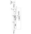
- FIG. 2 is a diagram for explaining a basic configuration example of the optical amplifier 31 in the present invention.
- the optical amplifier 31 includes an optical parametric amplification section 32 , a pumping light source 33 , a pumping light multiplexing section 34 for Raman amplification, and an optical isolator 35 .
- the optical parametric amplifier 32 is composed of, for example, a highly nonlinear fiber and a periodically poled lithium niobate (PPLN) waveguide.
- PPLN periodically poled lithium niobate
- the excitation light source 33 outputs excitation light with a predetermined wavelength and intensity.
- the wavelength of the pumping light output by the pumping light source 33 is set based on the wavelength of the optical signal input to the optical amplifier 31 .
- the Raman amplification pumping light multiplexing unit 34 performs forward pumping Raman amplification based on the optical signal amplified by the optical parametric amplification unit 32 and the pumping light output from the pumping light source 33 .
- the Raman amplification pumping light combiner 34 controls the gain so as to shift the optimum input light power in the optical fiber transmission line to a region where the output of the optical parametric amplifier 32 is linearly amplified.
- the optical isolator 35 transmits forward light and blocks backward light.
- the optical isolator 35 transmits light proceeding to the optical fiber transmission line and blocks light input in the direction of the Raman amplification pumping light combiner 34 .
- FIG. 3 shows a measurement example of the relationship between the optical signal quality (SNR) and the optical fiber input power when optically amplified relay transmission is carried out over 2,000 km with the configuration of the amplifier shown in the legend.
- FIG. 4 shows the results of comparison between the conventional configuration and the present invention regarding the gain/noise figure, input wavelength number (power) variation characteristics, and broadband characteristics.
- the configuration shown in FIG. 2 is that of an optical amplifier 31 capable of amplifying and repeating an optical signal of one wavelength. will be described.
- FIG. 5 is a diagram showing a configuration example of the optical amplifier 31 in the first embodiment.
- the optical amplifier 31 includes an optical isolator 311, a band-splitting filter 312, a plurality of variable attenuators 313-1 and 313-2, a plurality of OPAs 314-1 and 314-2, and a plurality of monitors 315-1 and 315- 2, a band synthesizing/gain equalizing unit 316, a variable attenuation unit 317, a plurality of pumping light sources 318-1 to 318-n (n is an integer of 2 or more), a pumping light combining unit 319, and an optical isolator 320.
- a WDM signal is input to the optical amplifier 31 .
- the configuration shown in FIG. 5 can be applied as an optical amplifying repeater and a post-amplifier.
- the optical isolator 311 transmits forward light and blocks backward light.
- optical isolator 311 transmits light traveling to band-splitting filter 312 and blocks the input of light in the direction toward the optical fiber transmission line.
- Band splitting filter 312 splits the input WDM signal into two bands. Specifically, the band splitting filter 312 splits the WDM signal into a long wavelength band optical signal and a short wavelength band optical signal, for example, based on the fundamental wavelength ⁇ F . By the band splitting filter 312, the optical signal in the long wavelength band is output to the variable attenuator 313-1, and the optical signal in the short wavelength band is output to the variable attenuator 313-2.
- the phase conjugate light (idler light) generated around the fundamental wavelength ⁇ F in the process of optical parametric amplification is unnecessary. and amplified with OPA314-1 and 314-2.
- the pump light for distributed Raman amplification is included in the input signal (WDM signal), the band-splitting filter 312 and the pump light elimination filter shown in FIG. The pump light for Raman amplification is separated/removed from the WDM signal.
- variable attenuator 313-1 adjusts the power of the optical signal in the long wavelength band.
- the amount of attenuation by variable attenuator 313-1 is set based on the monitor 315-1 output power output power output from OPA 314-1. The power of the optical signal is adjusted.
- variable attenuator 313-2 adjusts the power of the optical signal in the short wavelength band.
- the amount of attenuation by variable attenuator 313-2 is set based on the monitor 315-2 output power output power output from OPA 314-2. The power of the optical signal is adjusted.
- the OPA314-1 is composed of, for example, a highly nonlinear fiber and a periodically poled lithium niobate (PPLN) waveguide.
- the OPA 314-1 amplifies the input optical signal using the nonlinear optical effect.
- OPA 314-1 amplifies WDM signals in the long wavelength band.
- the OPA 314-1 sets the pumping light level of the OPA 314-1 based on the monitor 315-1 monitoring the output power of the OPA 314-1, and performs amplification at the set pumping light level.
- the OPA314-2 is composed of, for example, a highly nonlinear fiber and a periodically poled lithium niobate waveguide.
- the OPA 314-2 amplifies the input optical signal using the nonlinear optical effect.
- OPA 314-2 amplifies WDM signals in the short wavelength band.
- the OPA 314-2 sets the pumping light level of the OPA 314-2 based on the result of monitoring the output power of the OPA 314-2 by the monitor 315-2, and performs amplification at the set pumping light level.
- the monitors 315-1 and 315-2 monitor the output power of the OPA's 314-1 and 314-2 in order to control the gain saturation of the OPA's 314-1 and 314-2.
- the operation region where gain saturation occurs with respect to pumping light and input signal power of OPAs 314-1 and 314-2 can be obtained by measuring in advance or by detecting distortion in the receiver of the optical transmission system. can.
- the band synthesizing/gain equalizing unit 316 synthesizes the long wavelength band WDM signal whose optical power is amplified by the OPA 314-1 and the short wavelength band WDM signal whose optical power is amplified by the OPA 314-2. After that, band synthesis/gain equalization section 316 performs gain equalization.
- variable attenuation section 317 adjusts the input power of the WDM signal output from the band synthesis/gain equalization section 316 .
- the excitation light sources 318-1 to 318-n output excitation light of different wavelengths.
- the pumping light sources 318-1 to 318-n have a wavelength band shifted to the short wavelength side by about 100 nm with respect to the WDM signal.
- an incoherent light source in a multi-repeater transmission or high Raman amplification gain region.
- a plurality of wavelengths may be bundled including a light source for polarization multiplexing and secondary excitation.
- the forward-pumped Raman amplification gain is set at the pump source output such that the optimum optical fiber input power falls within the non-gain-saturated regions of OPAs 314-1 and 314-2.
- the excitation light multiplexing unit 319 multiplexes the excitation light output from each of the excitation light sources 318-1 to 318-n and the WDM signal.
- the optical isolator 320 transmits forward light and blocks backward light.
- the optical isolator 320 transmits light traveling to the optical fiber transmission line and blocks input of light in the direction toward the pumping light multiplexing unit 319 .
- the gain of this optical amplifier repeater is set so that the sum of the forward Raman gain GRF and the gain GOPA due to the OPA is equal to the loss of the transmission line to be repeated.
- FIG. 6 is a flow chart showing the flow of processing performed by the optical amplifier 31 in the first embodiment.
- the band division filter 312 divides the input WDM signal into two bands (step S101).
- the optical signal in the long wavelength band split by the band splitting filter 312 is output to the variable attenuator 313-1, and the optical signal in the short wavelength band is output to the variable attenuator 313-2.
- the variable attenuator 313-1 adjusts the power of the optical signal in the long wavelength band (step S102).
- the variable attenuator 313-1 outputs the optical signal in the long wavelength band after power adjustment to the OPA 314-1.
- the OPA 314-1 amplifies the WDM signal in the long wavelength band (step S103).
- OPA 314-1 outputs the amplified WDM signal of the long wavelength band to band synthesis/gain equalization section 316 via monitor 315-1.
- the monitor 315-1 monitors the output power of the amplified long-wavelength band WDM signal output from the OPA 314-1. Feedback control for the variable attenuator 313-1 and the OPA 314-1 based on the monitor result by the monitor 315-1 is executed each time the monitor result is obtained.
- the variable attenuator 313-2 adjusts the power of the optical signal in the short wavelength band (step S104).
- the variable attenuator 313-2 outputs the short wavelength band optical signal after power adjustment to the OPA 314-2.
- the OPA 314-2 amplifies the short wavelength band WDM signal (step S105).
- the OPA 314-2 outputs the amplified short wavelength band WDM signal to the band synthesis/gain equalization section 316 via the monitor 315-1.
- the monitor 315-2 monitors the output power of the amplified long-wavelength band WDM signal output from the OPA 314-2. Feedback control for the variable attenuator 313-2 and the OPA 314-2 based on the monitor result by the monitor 315-2 is executed each time the monitor result is obtained.
- a band synthesis/gain equalization unit 316 synthesizes and gains the long wavelength band WDM signal whose optical power is amplified by the OPA 314-1 and the short wavelength band WDM signal whose optical power is amplified by the OPA 314-2. (step S106).
- the WDM signal combined and gain-equalized by band combining/gain equalizing section 316 is input to variable attenuation section 317 .
- the variable attenuator 317 adjusts the input power of the WDM signal (step S107).
- the variable attenuator 317 outputs the WDM signal after the input power adjustment to the excitation light combiner 319 .
- the pumping light multiplexing unit 319 multiplexes the pumping light output from each of the pumping light sources 318-1 to 318-n and the WDM signal, thereby performing forward pumping Raman amplification (step S108).
- the WDM signal Raman-amplified by the pumping light combiner 319 is output to the optical fiber transmission line.
- the optical amplifier 31 configured as described above, it is possible to perform broadband and high-quality optical amplifying repeater in optical amplifying repeater using optical parametric amplification. Specifically, the optical amplifier 31 performs optical parametric amplification on the input optical signal, and shifts the optimum input optical power in the optical fiber transmission line to a region where the output of the optical parametric amplifier is linearly amplified. to control the gain.
- an optical amplifying repeater using optical parametric amplification can: It is possible to realize optical amplification repeater transmission of wideband and high-quality wavelength multiplexed signals.
- the optical amplifier has, in addition to the configuration of the first embodiment, a configuration for backward pumping Raman amplification using an optical fiber transmission line connected to the input side of the optical amplifier as an amplification medium.
- FIG. 7 is a diagram showing a configuration example of the optical amplifier 31a in the second embodiment.
- the optical amplifier 31a includes an optical isolator 311, a band-splitting filter 312, a plurality of variable attenuators 313-1 and 313-2, a plurality of OPAs 314-1 and 314-2, and a plurality of monitors 315-1 and 315- 2, a band synthesizing/gain equalizing unit 316, a variable attenuation unit 317, a plurality of pumping light sources 318-1 to 318-n (n is an integer of 2 or more), a pumping light combining unit 319, and an optical isolator 320. , a plurality of excitation light sources 321-1 to 321-n, and an excitation light multiplexing unit 322.
- the optical amplifier 31a differs in configuration from the optical amplifier 31 in that it newly includes a plurality of pumping light sources 321-1 to 321-n and a pumping light multiplexing unit 322. Other configurations of the optical amplifier 31 a are the same as those of the optical amplifier 31 . Therefore, differences based on the plurality of pumping light sources 321-1 to 321-n and the pumping light multiplexing unit 322 will be described.
- the basic operation is the same as in the first embodiment, but the RIN transfer is very small in backward-pumped Raman amplification. Therefore, as the pumping light sources 321-1 to 321-n, a wavelength band shifted to the short wavelength side by about 100 nm with respect to the WDM signal is used, and both coherent light sources and incoherent light sources can be applied. Light sources of multiple wavelengths may be bundled, including light sources for polarization multiplexing and secondary excitation.
- the forward-pumped Raman amplification gain is set at the output of the pump light source such that the optimum optical fiber input power is contained in the non-gain-saturated regions of OPAs 314-1 and 314-2.
- the variable attenuator 317 adjusts the input power of the WDM signal to the transmission line optical fiber.
- the excitation light multiplexing unit 322 multiplexes the excitation light output from each of the excitation light sources 321-1 to 321-n and the WDM signal.
- the gain of this optical amplifying repeater is set so that the sum of the forward Raman gain GRF, the gain GOPA due to the OPA, and the backward Raman gain GRB is equal to the loss of the transmission line to be repeated.
- FIG. 8 is a flow chart showing the flow of processing performed by the optical amplifier 31a in the second embodiment.
- the pumping light multiplexing unit 322 multiplexes the pumping light output from each of the pumping light sources 321-1 to 321-n and the input WDM signal, thereby performing backward pumping Raman amplification (step S201).
- the WDM signal Raman-amplified by the pumping light combiner 322 is output to the band division filter 312 via the optical isolator 311 . After that, the processes after step S101 are executed.
- the optical amplifier 31b can obtain the same effects as in the first embodiment even when bidirectional pumping Raman amplification is applied.
- the optical amplifier 31b by applying backward pumping Raman amplification to the configuration of the first embodiment, the SNR after transmission can be improved compared to the first embodiment.
- FIG. 9 is a diagram for explaining the effects of the first embodiment and the second embodiment.
- an optical parametric amplifier alone is used to achieve a fiber input power equivalent to that of a conventional rare-earth-doped fiber optical amplifier repeater represented by a conventional EDFA, the signal is distorted due to gain saturation. The signal quality after amplification is limited in the wide amplification band covered by .
- the configurations shown in the first and second embodiments enable optical amplifier repeater transmission of wideband and high-quality WDM signals. know that it will be possible.
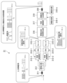
- FIG. 10 is a diagram showing a configuration example of the optical amplifier 31b in the third embodiment.
- the optical amplifier 31 b includes a control section 330 , an SW 331 , a plurality of OPAs 314 - 1 to 314 - 3 , a wavelength selective switch 332 and a Raman amplification section 333 .
- FIG. 10 shows an example in which optical signals are input from separate routes 1 to 3 to the optical amplifier 31b, which is a relay node. It is assumed that the optical signal input to the optical amplifier 31b uses wavelengths in the C band for route 1, the C band for route 2, and the S band for route 3.
- OPAs 314-1 to 314-3 are optical parametric amplifiers capable of amplifying a set frequency band.
- OPA314-1 can amplify the C and L bands
- OPA314-2 can amplify the S and C bands
- OPA314-3 can amplify the S and C bands. do.
- the control unit 330 controls the SW 331 and the wavelength selective switch 332.
- the control of the SW 331 and the wavelength selective switch 332 is path switching.
- the SW 331 has multiple input ports and multiple output ports.
- the connection relationship between the input port and the output port of the SW 331 is controlled by the control section 330 .
- the SW 331 controls the path connecting the input port and the output port so as to allocate the signal to the OPA 314 capable of amplifying each band.
- the optical signal input from route 1 is an optical signal in the C band
- it is input to the OPA 314-1 capable of amplifying the C and L bands
- the optical signal input from route 2 is in the C band. Therefore, the C band and S band are input to the OPA 314-2, which can be amplified.
- the path connecting the input port and the output port is controlled by the control unit 330 so that the signal is input to the OPA 314-3.
- the wavelength selective switch 332 selects bands so that the bands amplified by the OPAs 314-1 to 314-3 do not collide.
- the wavelength selective switch 332 selects an L-band optical signal from the output of the OPA 314-1, selects a C-band optical signal from the output of the OPA 314-2, and selects a C-band optical signal from the OPA 314-3.
- An S-band optical signal is selected from the output.
- the wavelength selective switch 332 multiplexes the optical signals of each selected band.
- the Raman amplifier 333 multiplexes the optical signal multiplexed by the wavelength selective switch 332 and pumping light of an appropriate wavelength, and amplifies the optical signal to the optimum input power of the transmission line fiber input.
- An amplification fiber may also be used.
- the present invention can be applied to optical repeaters in optical transmission systems.
Abstract
光ファイバ伝送路で伝送される光信号を光増幅中継する光増幅器であって、入力された光信号に光パラメトリック増幅を行う光パラメトリック増幅部と、光ファイバ伝送路における最適入力光パワーを、光パラメトリック増幅部の出力が線形増幅となる領域にパワーシフトさせるよう利得を制御するラマン増幅部と、を備える光増幅器。
Description
本発明は、光増幅器及び光増幅方法に関する。
現在の一般的な波長多重光増幅中継伝送システムは、単一の波長帯の4~5THzのC帯もしくはL帯を用いて構成されており、送受信機の高度化により、システムあたりの伝送容量の拡大をはかってきた(例えば、非特許文献1参照)。しかしながら、デジタルコヒーレント技術が成熟し送受信機の高度化による大容量化が難しい領域に差し掛かっており、波長多重可能な光帯域を増やすこと(広帯域化)が重要になっている。
従来の光増幅中継伝送システムの広帯域化は、利用したい光帯域に対応した希土類添加光ファイバ型増幅器(EDFA(Erbium Doped Fiber Amplifier),BDFA(Bithmus Doped Fiber Amplifier)など)や半導体光増幅器(SOA:Semiconductor Optical Amplifier)を複数使い、場合によっては、伝送路自体を増幅媒体として用いる励起光波長で増幅帯域の制御が可能な後方励起分布ラマン増幅との組合わせで実現されている。従来方式では、使用する増幅器ごとに利得や雑音指数の波長依存性が異なるため、光増幅中継器の構成や伝送システム設計が複雑になる課題があった。
希土類添加光ファイバ型増幅器や半導体光増幅器は、入力光信号パワーの急激な変動に対して光サージが生じて信号品質の低下や光部品へのダメージが懸念されるため、波長数の増減が想定される波長資源を豊富に活用する将来的な光ネットワークへの適用に課題があった。そのような背景から、偏波多重信号の増幅が可能で、広帯域性や高速応答性に優れる光パラメトリック増幅の光増幅中継器への適用が検討されている(例えば、非特許文献2参照)。
川崎 他, "Beyond 100G オプティカルクロスコネクト(B100G-OXC)システムの実用化", NTT技術ジャーナル, https://journal.ntt.co.jp/article/14780
Takayuki Kobayashi et al., "Wide-Band Inline-Amplified WDM Transmission Using PPLN-Based Optical Parametric Amplifier", J. Lightwave Technol. 39, 787-794 (2021)
T. Kobayashiet al., "13.4-Tb/s WDM Transmission over 1,280 km Repeated only with PPLN-based Optical Parametric Inline Amplifier", 2021 European Conference on Optical Communication (ECOC), 2021, Tu4C1.3, doi: 10.1109/ECOC52684.2021.9605912.
従来のEDFAでは、利得が飽和する動作領域おいて光信号に歪みは生じないが、光パラメトリック増幅器(OPA:Optical Parametric Amplifier)では、利得飽和が発生する領域においては、その高速応答性から光信号の振幅成分の大きさに応じて利得が変動し、信号に歪みが生じる。そのため、光パラメトリック増幅器は高利得化と高出力化の両立が難しい。従来の光パラメトリック増幅器のみを適用した光増幅中継伝送では、伝送路ファイバへの入力パワーを高くして信号対雑音比を向上させようとすると、光パラメトリック増幅器における利得飽和のために信号が歪み、信号品質が低下する。そのため、光パラメトリック増幅器がカバーする広帯域な増幅帯域において、増幅後の信号品質が制限されてしまうという問題があった。
上記事情に鑑み、本発明は、光パラメトリック増幅を用いた光増幅中継において、広帯域かつ高品質な光増幅中継を行うことができる技術の提供を目的としている。
本発明の一態様は、光ファイバ伝送路で伝送される光信号を光増幅中継する光増幅器であって、入力された光信号に光パラメトリック増幅を行う光パラメトリック増幅部と、前記光ファイバ伝送路における最適入力光パワーを、前記光パラメトリック増幅部の出力が線形増幅となる領域にパワーシフトさせるよう利得を制御するラマン増幅部と、を備える光増幅器である。
本発明の一態様は、光ファイバ伝送路で伝送される光信号を光増幅中継する光増幅器における光増幅方法であって、光パラメトリック増幅部が、入力された光信号に光パラメトリック増幅を行い、前記光ファイバ伝送路における最適入力光パワーを、前記光パラメトリック増幅部の出力が線形増幅となる領域にパワーシフトさせるよう利得を制御する、光増幅方法である。
本発明により、光パラメトリック増幅を用いた光増幅中継において、広帯域かつ高品質な光増幅中継を行うことが可能となる。
以下、本発明の一実施形態を、図面を参照しながら説明する。
図1は、本発明における光伝送システム100の構成例を示す図である。光伝送システム100は、複数の光送信機10-1~10-N(Nは2以上の整数)と、光合分波器20と、光増幅中継伝送路30と、光合分波器40と、複数の光受信機50-1~50-Nとを備える。光増幅中継伝送路30は、1以上の光増幅器31と光ファイバ伝送路とを用いて構成される。
光送信機10-1~10-Nは、異なる波長の光信号を送信する。例えば、光送信機10-1は波長1の光信号を送信し、光送信機10-Nは波長Nの光信号を送信する。
光合分波器20は、光送信機10-1~10-Nから送信された異なる波長の光信号を波長分割多重により合波してWDM信号を生成する。光合分波器20は、生成したWDM信号を光増幅中継伝送路30に出力する。
光増幅器31は、光合分波器20から出力されたWDM信号を増幅して伝送する。より具体的には、光増幅器31は、WDM信号に対して、光パラメトリック増幅及びラマン増幅を行う。
光合分波器40は、光増幅器31により増幅されたWDM信号を分波する。例えば、光合分波器40は、WDM信号を波長1~波長Nの光信号に分波して光受信機50-1~50-Nに出力する。
光受信機50-1~50-Nは、光合分波器40により分波された光信号を受信する。例えば、光受信機50-1は波長1の光信号を受信し、光受信機50-Nは波長Nの光信号を受信する。
図2は、本発明における光増幅器31の基本構成例を説明するための図である。光増幅器31は、光パラメトリック増幅部32と、励起光源33と、ラマン増幅用励起光合波部34と、光アイソレータ35とを備える。
光パラメトリック増幅部32は、例えば高非線形ファイバ及び周期分極反転ニオブ酸リチウム(PPLN:Periodically Poled Lithium Niobate)導波路で構成される。光パラメトリック増幅部32は、非線形光学効果を利用して、入力された光信号を増幅する。
励起光源33は、予め定められた波長と強度の励起光を出力する。励起光源33が出力する励起光の波長は、光増幅器31に入力される光信号の波長に基づいて設定される。
ラマン増幅用励起光合波部34は、光パラメトリック増幅部32により増幅された光信号と、励起光源33から出力された励起光とに基づいて前方励起のラマン増幅を行う。ラマン増幅用励起光合波部34は、光ファイバ伝送路における最適入力光パワーを、光パラメトリック増幅部32の出力が線形増幅となる領域にパワーシフトさせるよう利得を制御する。
光アイソレータ35は、順方向に進む光を透過し、逆方向の光を遮断する。例えば、光アイソレータ35は、光ファイバ伝送路に進む光を透過し、ラマン増幅用励起光合波部34の方向への光の入力を遮断する。
以上が、本発明における光増幅器31の基本的な構成に関する説明する。このように、光パラメトリック増幅と前方励起のラマン増幅とを組み合わせた場合の効果について説明する。図3及び図4は、光パラメトリック増幅と前方励起のラマン増幅とを組み合わせた場合の効果を説明するための図である。図3には、凡例に示す増幅器の構成で2,000km光増幅中継伝送したときの光信号の品質(SNR)と光ファイバ入力パワーの関係の測定例を示している。図4には、利得・雑音指数、入力波長数(パワー)変動特性及び広帯域性に関する従来構成と、本発明の比較結果を示している。
図3に示すように、増幅器(EDFA)に、前方励起のラマン増幅(前方励起の分布ラマン増幅)の適用により、信号品質の上限値は略同等であるが、最適入力パワーは低い領域にシフトする。この最適パワーのシフト量は、前方励起のラマン増幅の利得により制御することが出来る。前方励起のラマン増幅による最適パワーシフトの特性を利用して、本発明のように光パラメトリック増幅器の線形増幅領域まで、前方励起のラマン増幅の利得を制御することで、光パラメトリック増幅の広帯域性と高速応答性を損なうことなく、高い信号品質で広帯域光増幅中継が可能になる。下記参考文献1に記載されているように、コヒーレンシーの高い励起光源を前方励起分布ラマン増幅に用いると、一定以上のラマン利得ではRINトランスファの影響で信号品質が大きく劣化してしまうため、実施形態によっては光スペクトルが広がったインコヒーレント光源を前方励起光源として用いることが望ましい。
(参考文献1:Takayuki Kobayashi, Masahito Morimoto, Haruki Ogoshi, Shigehiro Takasaka, Junji Yoshida, Yutaka Miyamoto, “2nd-order forward-pumped distributed Raman amplification employing SOA-based incoherent light source in PDM-16QAM WDM transmission system”, IEICE Communications Express, Vol.8, No. 5, p. 166-171, 2019.)
図2に示した構成は、1波長の光信号を増幅中継可能な光増幅器31の構成であり、上述した原理を利用して、波長多重された複数の光信号を増幅中継可能な光増幅器31の構成について説明する。
(第1の実施形態)
図5は、第1の実施形態における光増幅器31の構成例を示す図である。光増幅器31は、光アイソレータ311と、帯域分割フィルタ312と、複数の可変減衰部313-1,313-2と、複数のOPA314-1,314-2と、複数のモニタ315-1,315-2と、帯域合成/利得等化部316と、可変減衰部317と、複数の励起光源318-1~318-n(nは2以上の整数)と、励起光合波部319と、光アイソレータ320とを備える。光増幅器31には、WDM信号が入力される。図5に示す構成は、光増幅中継部及びポストアンプとして適用できる。
図5は、第1の実施形態における光増幅器31の構成例を示す図である。光増幅器31は、光アイソレータ311と、帯域分割フィルタ312と、複数の可変減衰部313-1,313-2と、複数のOPA314-1,314-2と、複数のモニタ315-1,315-2と、帯域合成/利得等化部316と、可変減衰部317と、複数の励起光源318-1~318-n(nは2以上の整数)と、励起光合波部319と、光アイソレータ320とを備える。光増幅器31には、WDM信号が入力される。図5に示す構成は、光増幅中継部及びポストアンプとして適用できる。
光アイソレータ311は、順方向に進む光を透過し、逆方向の光を遮断する。例えば、光アイソレータ311は、帯域分割フィルタ312に進む光を透過し、光ファイバ伝送路に向かう方向への光の入力を遮断する。
帯域分割フィルタ312は、入力されたWDM信号を2つの帯域に分割する。具体的には、帯域分割フィルタ312は、例えば、帯域分割フィルタ312は、基本波長λFを基準にしてWDM信号を長波長帯の光信号と、短波長帯の光信号とに分割する。帯域分割フィルタ312により、長波長帯の光信号は可変減衰部313-1に出力され、短波長帯の光信号は可変減衰部313-2に出力される。
OPAで入力信号を増幅する場合は、光パラメトリック増幅の過程で基本波長λFを中心にして発生する位相共役光(アイドラ光)が不要であるため、帯域分割フィルタ312によりWDM信号を2つの帯域に分けて、OPA314-1及び314-2で増幅する。なお、分布ラマン増幅用の励起光が入力信号(WDM信号)に含まれている場合、図5の帯域分割フィルタ312、励起光除去フィルタを別途、光増幅器31の入力側に配置して、前方ラマン増幅用励起光をWDM信号から分離・除去する。
可変減衰部313-1は、長波長帯の光信号のパワーを調整する。可変減衰部313-1においては、モニタ315-1によるOPA314-1の出力パワーのモニタ結果に基づいて可変減衰部313-1による減衰量が設定され、OPA314-1へ入力される長波長帯の光信号のパワーが調整される。
可変減衰部313-2は、短波長帯の光信号のパワーを調整する。可変減衰部313-2においては、モニタ315-2によるOPA314-2の出力パワーのモニタ結果に基づいて可変減衰部313-2による減衰量が設定され、OPA314-2へ入力される短波長帯の光信号のパワーが調整される。
OPA314-1は、例えば高非線形ファイバ及び周期分極反転ニオブ酸リチウム(PPLN:Periodically Poled Lithium Niobate)導波路で構成される。OPA314-1は、非線形光学効果を利用して、入力された光信号を増幅する。例えば、OPA314-1は、長波長帯のWDM信号を増幅する。OPA314-1は、モニタ315-1によるOPA314-1の出力パワーのモニタ結果に基づいてOPA314-1の励起光レベルが設定され、設定された励起光レベルで増幅を行う。
OPA314-2は、例えば高非線形ファイバ及び周期分極反転ニオブ酸リチウム導波路で構成される。OPA314-2は、非線形光学効果を利用して、入力された光信号を増幅する。例えば、OPA314-2は、短波長帯のWDM信号を増幅する。OPA314-2は、モニタ315-2によるOPA314-2の出力パワーのモニタ結果に基づいてOPA314-2の励起光レベルが設定され、設定された励起光レベルで増幅を行う。
モニタ315-1,315-2は、OPA314-1,314-2の利得飽和制御を行うために、OPA314-1,314-2の出力パワーをモニタする。OPA314-1,314-2の励起光や入力信号パワーに対する利得飽和の発生するオペレーション領域は、事前に測定しておくか、光伝送システムの受信機でひずみを検知するなどして、得ることができる。
帯域合成/利得等化部316は、OPA314-1により光パワーが増幅された長波長帯のWDM信号と、OPA314-2により光パワーが増幅された短波長帯のWDM信号とを合成する。その後、帯域合成/利得等化部316は、利得等化を行う。
可変減衰部317は、帯域合成/利得等化部316から出力されたWDM信号の入力パワーを調整する。
励起光源318-1~318-nは、異なる波長の励起光を出力する。励起光源318-1~318-nは、WDM信号に対して100nm程度短波長側にシフトした波長帯のものが用いられる。RINトランスファーによる信号品質劣化を避けるために、多中継伝送や高いラマン増幅利得の領域では、インコヒーレント光源を用いることが好ましい。偏波多重や2次励起用の光源を含めて複数波長を束ねてもよい。前方励起のラマン増幅利得は、最適な光ファイバ入力パワーがOPA314-1及び314-2の非利得飽和領域に含まれるように励起光源の出力を設定される。
励起光合波部319は、励起光源318-1~318-nそれぞれから出力された励起光と、WDM信号とを合波する。
光アイソレータ320は、順方向に進む光を透過し、逆方向の光を遮断する。例えば、光アイソレータ320は、光ファイバ伝送路に進む光を透過し、励起光合波部319に向かう方向への光の入力を遮断する。
本光増幅中継器の利得は、前方ラマン利得GRFとOPAによる利得GOPAの和が、中継する伝送路の損失と等しくなるように設定される。
図6は、第1の実施形態における光増幅器31が行う処理の流れを示すフローチャートである。
帯域分割フィルタ312は、入力されたWDM信号を2つの帯域に分割する(ステップS101)。帯域分割フィルタ312により分割された長波長帯の光信号は可変減衰部313-1に出力され、短波長帯の光信号は可変減衰部313-2に出力される。可変減衰部313-1は、長波長帯の光信号のパワーを調整する(ステップS102)。可変減衰部313-1は、パワー調整後の長波長帯の光信号をOPA314-1に出力する。OPA314-1は、長波長帯のWDM信号を増幅する(ステップS103)。OPA314-1は、増幅後の長波長帯のWDM信号を、モニタ315-1を介して帯域合成/利得等化部316に出力する。
帯域分割フィルタ312は、入力されたWDM信号を2つの帯域に分割する(ステップS101)。帯域分割フィルタ312により分割された長波長帯の光信号は可変減衰部313-1に出力され、短波長帯の光信号は可変減衰部313-2に出力される。可変減衰部313-1は、長波長帯の光信号のパワーを調整する(ステップS102)。可変減衰部313-1は、パワー調整後の長波長帯の光信号をOPA314-1に出力する。OPA314-1は、長波長帯のWDM信号を増幅する(ステップS103)。OPA314-1は、増幅後の長波長帯のWDM信号を、モニタ315-1を介して帯域合成/利得等化部316に出力する。
なお、モニタ315-1では、OPA314-1から出力された増幅後の長波長帯のWDM信号の出力パワーをモニタする。モニタ315-1によるモニタ結果に基づく可変減衰部313-1及びOPA314-1に対するフィードバック制御は、モニタ結果が得られる度に実行される。
可変減衰部313-2は、短波長帯の光信号のパワーを調整する(ステップS104)。可変減衰部313-2は、パワー調整後の短波長帯の光信号をOPA314-2に出力する。OPA314-2は、短波長帯のWDM信号を増幅する(ステップS105)。OPA314-2は、増幅後の短波長帯のWDM信号を、モニタ315-1を介して帯域合成/利得等化部316に出力する。
なお、モニタ315-2では、OPA314-2から出力された増幅後の長波長帯のWDM信号の出力パワーをモニタする。モニタ315-2によるモニタ結果に基づく可変減衰部313-2及びOPA314-2に対するフィードバック制御は、モニタ結果が得られる度に実行される。
帯域合成/利得等化部316は、OPA314-1により光パワーが増幅された長波長帯のWDM信号と、OPA314-2により光パワーが増幅された短波長帯のWDM信号とを合成及び利得等化する(ステップS106)。帯域合成/利得等化部316により合成されて利得等化されたWDM信号は、可変減衰部317に入力される。可変減衰部317は、WDM信号の入力パワーを調整する(ステップS107)。可変減衰部317は、入力パワー調整後のWDM信号を励起光合波部319に出力する。
励起光合波部319は、励起光源318-1~318-nそれぞれから出力された励起光と、WDM信号とを合波することで前方励起のラマン増幅を行う(ステップS108)。励起光合波部319によりラマン増幅されたWDM信号は、光ファイバ伝送路に出力される。
以上のように構成された光増幅器31によれば、光パラメトリック増幅を用いた光増幅中継において、広帯域かつ高品質な光増幅中継を行うことが可能になる。具体的には、光増幅器31では、入力された光信号に光パラメトリック増幅を行い、光ファイバ伝送路における最適入力光パワーを、光パラメトリック増幅部の出力が線形増幅となる領域にパワーシフトさせるよう利得を制御するする。このように、光増幅器31では、ラマン増幅を適用し、光パラメトリック増幅器が線形増幅出力可能な領域にシフトさせること(分布ラマン増幅の場合)で、光パラメトリック増幅を用いた光増幅中継器で、広帯域かつ高品質な波長多重信号の光増幅中継伝送を実現することができる。
(第2の実施形態)
第2の実施形態では、第1の実施形態を光増幅中継器として光伝送システムに適用する構成について説明する。この場合、光増幅器は、第1の実施形態の構成に加えて、光増幅器の入力側に接続される光ファイバ伝送路を増幅媒体とする後方励起ラマン増幅用の構成を備える。
第2の実施形態では、第1の実施形態を光増幅中継器として光伝送システムに適用する構成について説明する。この場合、光増幅器は、第1の実施形態の構成に加えて、光増幅器の入力側に接続される光ファイバ伝送路を増幅媒体とする後方励起ラマン増幅用の構成を備える。
図7は、第2の実施形態における光増幅器31aの構成例を示す図である。光増幅器31aは、光アイソレータ311と、帯域分割フィルタ312と、複数の可変減衰部313-1,313-2と、複数のOPA314-1,314-2と、複数のモニタ315-1,315-2と、帯域合成/利得等化部316と、可変減衰部317と、複数の励起光源318-1~318-n(nは2以上の整数)と、励起光合波部319と、光アイソレータ320と、複数の励起光源321-1~321-nと、励起光合波部322とを備える。
光増幅器31aは、複数の励起光源321-1~321-nと、励起光合波部322とを新たに備える点で光増幅器31と構成が異なる。光増幅器31aのその他の構成については、光増幅器31と同様である。そのため、複数の励起光源321-1~321-nと、励起光合波部322を踏まえた相違点について説明する。
第2の実施形態において、基本的な動作は第1の実施形態と同等であるが、後方励起のラマン増幅では、RINトランスファーが非常に小さい。そのため、励起光源321-1~321-nとして、WDM信号に対して100nm程度短波長側にシフトした波長帯のものを用い、コヒーレント光源及びインコヒーレント光源どちらも適用することができる。偏波多重や2次励起用の光源を含めて複数波長の光源を束ねてもよい。
前方励起のラマン増幅利得は、最適な光ファイバ入力パワーがOPA314-1及び314-2の非利得飽和領域に含まれるように励起光源の出力を設定される。可変減衰部317により、伝送路光ファイバへのWDM信号の入力パワーが調整される。
励起光合波部322は、励起光源321-1~321-nそれぞれから出力された励起光と、WDM信号とを合波する。
本光増幅中継器の利得は、前方ラマン利得GRF、OPAによる利得GOPA、および後方ラマン利得GRBの和が、中継する伝送路の損失と等しくなるように設定される。
図8は、第2の実施形態における光増幅器31aが行う処理の流れを示すフローチャートである。図8において、図6と同様の処理においては図6と同様の符号を付して説明を省略する。
励起光合波部322は、励起光源321-1~321-nそれぞれから出力された励起光と、入力されたWDM信号とを合波することで後方励起のラマン増幅を行う(ステップS201)。励起光合波部322によりラマン増幅されたWDM信号は、光アイソレータ311を介して、帯域分割フィルタ312に出力される。その後、ステップS101以降の処理が実行される。
励起光合波部322は、励起光源321-1~321-nそれぞれから出力された励起光と、入力されたWDM信号とを合波することで後方励起のラマン増幅を行う(ステップS201)。励起光合波部322によりラマン増幅されたWDM信号は、光アイソレータ311を介して、帯域分割フィルタ312に出力される。その後、ステップS101以降の処理が実行される。
以上のように構成された光増幅器31bによれば、光増幅器31bでは、双方向励起のラマン増幅を適用した場合においても、第1の実施形態と同様の効果を得ることができる。
光増幅器31bによれば、第1の実施形態の構成に後方励起のラマン増幅を適用することにより、第1の実施形態と比較して伝送後のSNRを改善することができる。
図9は、第1の実施形態及び第2の実施形態における効果を説明するための図である。図9に示すように、光パラメトリック増幅器のみで、従来のEDFAに代表される希土類添加ファイバ光増幅中継器と同等のファイバ入力パワーを実現しようとすると、利得飽和のために信号が歪むため、OPAがカバーする広帯域な増幅帯域において、増幅後の信号品質が制限される。波長多重光伝送システムにおいて、従来の希土類添加ファイバ光増幅中継器と比較して、第1の実施形態及び第2の実施形態に示す構成により、広帯域かつ高品質なWDM信号の光増幅中継伝送が可能になることがわかる。
(第3の実施形態)
第1の実施形態及び第2の実施形態では、2つの帯域に分割して光パラメトリック増幅を行う構成について説明した。第3の実施形態では、3つ以上の帯域において光パラメトリック増幅を行う構成について説明する。なお、第3の実施形態では、3つの帯域の場合について、光中継ノードとして適用する構成について説明する。
第1の実施形態及び第2の実施形態では、2つの帯域に分割して光パラメトリック増幅を行う構成について説明した。第3の実施形態では、3つ以上の帯域において光パラメトリック増幅を行う構成について説明する。なお、第3の実施形態では、3つの帯域の場合について、光中継ノードとして適用する構成について説明する。
図10は、第3の実施形態における光増幅器31bの構成例を示す図である。光増幅器31bは、制御部330と、SW331と、複数のOPA314-1~314-3と、波長選択性スイッチ332と、ラマン増幅部333とを備える。
図10では、別々の方路1~3から中継ノードである光増幅器31bに光信号が入力された例を示している。光増幅器31bに入力された光信号は、方路1がC帯、方路2がC帯、方路3がS帯の波長を用いているものとする。
OPA314-1~314-3は、設定された周波数帯を増幅可能な光パラメトリック増幅器である。例えば、OPA314-1は、C帯とL帯が増幅可能であり、OPA314-2は、S帯とC帯が増幅可能であり、OPA314-3は、S帯とC帯が増幅可能であるとする。
制御部330は、SW331及び波長選択性スイッチ332を制御する。SW331及び波長選択性スイッチ332の制御とは、経路の切替である。
SW331は、複数の入力ポートと、複数の出力ポートとを備える。SW331における入力ポートと、出力ポートとの接続関係は、制御部330により制御される。SW331では、それぞれの帯域を増幅可能なOPA314に信号を割り振るように、入力ポートと出力ポートとを接続する経路が制御される。例えば、方路1から入力された光信号は、C帯の光信号であるため、C帯とL帯が増幅可能なOPA314-1に入力され、方路2から入力された光信号はC帯の光信号であるため、C帯とS帯が増幅可能なOPA314-2に入力され、方路3から入力された光信号はS帯の光信号であるため、C帯とS帯が増幅可能なOPA314-3に入力されるように、制御部330により入力ポートと出力ポートとを接続する経路が制御される。
波長選択性スイッチ332は、各OPA314-1~314-3で増幅された帯域が衝突しないように帯域を選択する。図10に示す例では、波長選択性スイッチ332は、OPA314-1の出力からはL帯の光信号を選択し、OPA314-2の出力からはC帯の光信号を選択し、OPA314-3の出力からはS帯域の光信号を選択する。波長選択性スイッチ332は、選択した各帯域の光信号を合波する。
ラマン増幅部333は、波長選択性スイッチ332により合波された光信号と、適切な波長の励起光とを合波し、伝送路ファイバ入力の最適入力パワーまで光信号を増幅する。これにより、OPAが飽和パワー以下の出力領域で動作している場合において、広帯域かつ高品質な光中継増幅が実現することができる。なお、増幅用ファイバが用いられてもよい。
以上、この発明の実施形態について図面を参照して詳述してきたが、具体的な構成はこの実施形態に限られるものではなく、この発明の要旨を逸脱しない範囲の設計等も含まれる。
本発明は、光伝送システムにおける光中継器に適用できる。
10-1~10-N…光送信機, 20…光合分波器, 30…光増幅中継伝送路, 40…光合分波器, 50-1~50-N…光受信機, 31…光増幅器, 32…光パラメトリック増幅部, 33、318-1~318-n、321-1~321-n…励起光源, 34…ラマン増幅用励起光合波部, 35、311、320…光アイソレータ, 312…帯域分割フィルタ, 313-1、313-2、317…可変減衰部, 314-1、314-2…OPA, 315-1、315-2…モニタ, 316…帯域合成/利得等化部, 319、322…励起光合波部, 330…制御部, 331…SW, 332…波長選択性スイッチ, 333…ラマン増幅部
Claims (6)
- 光ファイバ伝送路で伝送される光信号を光増幅中継する光増幅器であって、
入力された光信号に光パラメトリック増幅を行う光パラメトリック増幅部と、
前記光ファイバ伝送路における最適入力光パワーを、前記光パラメトリック増幅部の出力が線形増幅となる領域にパワーシフトさせるよう利得を制御するラマン増幅部と、
を備える光増幅器。 - 前記光増幅器には、波長多重された多重信号が入力され、
前記光パラメトリック増幅部は、第1の光パラメトリック増幅部及び第2の光パラメトリック増幅部であり、
入力された前記多重信号を、基本波長を基準にして長波長帯の光信号と、短波長帯の光信号とに分割する帯域分割フィルタと、
前記長波長帯の光信号の光強度を調整する第1の可変減衰部と、
前記短波長帯の光信号の光強度を調整する第2の可変減衰部と、
増幅後の前記長波長帯の光信号と、増幅後の前記短波長帯の光信号とを合波する合波と、
をさらに備え、
前記第1の光パラメトリック増幅部は、前記第1の可変減衰部により光強度が調整された前記長波長帯の光信号に光パラメトリック増幅を行い、
第2の光パラメトリック増幅部は、前記第2の可変減衰部により光強度が調整された前記短波長帯の光信号に光パラメトリック増幅を行う、
請求項1に記載の光増幅器。 - 前記帯域分割フィルタの前段に備えられ、前記光ファイバ伝送路を増幅媒体とする後方励起のラマン増幅を行う後方ラマン増幅部、
をさらに備える請求項2に記載の光増幅器。 - 前記第1の光パラメトリック増幅部の出力パワーをモニタし、モニタ結果を前記第1の可変減衰部及び前記第1の光パラメトリック増幅部に出力する第1のモニタと、
前記第2の光パラメトリック増幅部の出力パワーをモニタし、モニタ結果を前記第2の可変減衰部及び前記第2の光パラメトリック増幅部に出力する第2のモニタと、
をさらに備え、
前記第1の可変減衰部は、前記第1のモニタから出力された前記モニタ結果に基づいて減衰量を調整し、
前記第1の光パラメトリック増幅部は、前記第1のモニタから出力された前記モニタ結果に基づいて励起光レベルを制御し、
前記第2の可変減衰部は、前記第2のモニタから出力された前記モニタ結果に基づいて減衰量を調整し、
前記第2の光パラメトリック増幅部は、前記第2のモニタから出力された前記モニタ結果に基づいて励起光レベルを制御する、
請求項2又は3に記載の光増幅器。 - 前記光パラメトリック増幅部は、複数の光パラメトリック増幅部であり、
複数の入力ポートと、複数の出力ポートとを備えるスイッチと、
前記複数の光パラメトリック増幅部それぞれから出力された光信号の周波数帯のうち、合波する周波数帯を選択する波長選択性スイッチと、
をさらに備え、
前記スイッチの出力ポートには、各光パラメトリック増幅部が接続され、
前記スイッチは、各入力ポートに入力された光信号毎に、前記光信号の周波数帯が増幅可能な光パラメトリック増幅部が接続されている出力ポートに光信号を出力する、
請求項1に記載の光増幅器。 - 光ファイバ伝送路で伝送される光信号を光増幅中継する光増幅器における光増幅方法であって、
光パラメトリック増幅部が、入力された光信号に光パラメトリック増幅を行い、
前記光ファイバ伝送路における最適入力光パワーを、前記光パラメトリック増幅部の出力が線形増幅となる領域にパワーシフトさせるよう利得を制御する、
光増幅方法。
Priority Applications (1)
| Application Number | Priority Date | Filing Date | Title |
|---|---|---|---|
| PCT/JP2022/008781 WO2023166590A1 (ja) | 2022-03-02 | 2022-03-02 | 光増幅器及び光増幅方法 |
Applications Claiming Priority (1)
| Application Number | Priority Date | Filing Date | Title |
|---|---|---|---|
| PCT/JP2022/008781 WO2023166590A1 (ja) | 2022-03-02 | 2022-03-02 | 光増幅器及び光増幅方法 |
Publications (1)
| Publication Number | Publication Date |
|---|---|
| WO2023166590A1 true WO2023166590A1 (ja) | 2023-09-07 |
Family
ID=87883209
Family Applications (1)
| Application Number | Title | Priority Date | Filing Date |
|---|---|---|---|
| PCT/JP2022/008781 WO2023166590A1 (ja) | 2022-03-02 | 2022-03-02 | 光増幅器及び光増幅方法 |
Country Status (1)
| Country | Link |
|---|---|
| WO (1) | WO2023166590A1 (ja) |
Citations (2)
| Publication number | Priority date | Publication date | Assignee | Title |
|---|---|---|---|---|
| JP2003298516A (ja) * | 2002-03-29 | 2003-10-17 | Fujitsu Ltd | 波長分散補償装置 |
| JP2018019350A (ja) * | 2016-07-29 | 2018-02-01 | 沖電気工業株式会社 | 光伝送システム、光伝送方法及び複素共役光生成部 |
-
2022
- 2022-03-02 WO PCT/JP2022/008781 patent/WO2023166590A1/ja unknown
Patent Citations (2)
| Publication number | Priority date | Publication date | Assignee | Title |
|---|---|---|---|---|
| JP2003298516A (ja) * | 2002-03-29 | 2003-10-17 | Fujitsu Ltd | 波長分散補償装置 |
| JP2018019350A (ja) * | 2016-07-29 | 2018-02-01 | 沖電気工業株式会社 | 光伝送システム、光伝送方法及び複素共役光生成部 |
Non-Patent Citations (1)
| Title |
|---|
| GUO XIAOJIE; SHU CHESTER: "Cross-Gain Modulation Suppression in a Raman-Assisted Fiber Optical Parametric Amplifier", IEEE PHOTONICS TECHNOLOGY LETTERS, IEEE, USA, vol. 26, no. 13, 1 July 2014 (2014-07-01), USA, pages 1360 - 1363, XP011551692, ISSN: 1041-1135, DOI: 10.1109/LPT.2014.2324566 * |
Similar Documents
| Publication | Publication Date | Title |
|---|---|---|
| JP5181770B2 (ja) | 光伝送システム | |
| JP4671478B2 (ja) | 波長多重光通信システムおよび波長多重光通信方法 | |
| US6741389B2 (en) | Optical transmission system and optical transmission method utilizing Raman amplification | |
| JP2002076482A (ja) | 光増幅器,光増幅方法及び光増幅システム | |
| JPWO2002035665A1 (ja) | 光送信機、光中継器及び光受信機並びに光送信方法 | |
| JP3779691B2 (ja) | 広帯域エルビウム添加光ファイバ増幅器及びこれを採用した波長分割多重化光伝送システム | |
| JP4487420B2 (ja) | 光増幅伝送システム | |
| US20090022499A1 (en) | Optical signal to noise ratio system | |
| JP2003188830A (ja) | 波長多重光伝送用装置、中継装置、分配装置及び波長多重光伝送システム | |
| Paolucci et al. | Filterless optical WDM metro networks exploiting C+ L band | |
| EP4038771B1 (en) | Optical amplifiers that support gain clamping and optionally power loading | |
| JP6088385B2 (ja) | 光伝送システム及び光伝送方法 | |
| JP2002164845A (ja) | 波長多重光送受信装置、波長多重光中継器、及び波長多重光通信システム | |
| US10090961B2 (en) | Multi-channel optical cross-phase modulation compensator | |
| WO2023166590A1 (ja) | 光増幅器及び光増幅方法 | |
| JP7063329B2 (ja) | 光中継器、光中継器の制御方法、及び光伝送システム | |
| US10498102B2 (en) | Optical phase-sensitive amplifier with signal noise removal | |
| Di Pasquale et al. | All-Raman transmission of 192 25-GHz spaced WDM channels at 10.66 Gb/s over 30 X 22 dB of TW-RS fiber | |
| US11438086B2 (en) | Optical amplification in an optical network | |
| JP2001168799A (ja) | 光通信システム及びそれに用いる光中継器 | |
| US8503881B1 (en) | Systems for extending WDM transmission into the O-band | |
| JP3596403B2 (ja) | 光波長分割多重送信装置及び光波長分割多重受信装置及び光中継装置及び光波長分割多重伝送システム | |
| JP6701265B2 (ja) | 光伝送システム及び光伝送方法 | |
| JPH1013382A (ja) | 光分岐挿入多重ノード装置 | |
| JP3866592B2 (ja) | ラマン増幅を用いた光伝送システム |
Legal Events
| Date | Code | Title | Description |
|---|---|---|---|
| 121 | Ep: the epo has been informed by wipo that ep was designated in this application |
Ref document number: 22929738 Country of ref document: EP Kind code of ref document: A1 |