WO2023162879A1 - セラミックス基材、セラミックス支持体および分離膜複合体 - Google Patents
セラミックス基材、セラミックス支持体および分離膜複合体 Download PDFInfo
- Publication number
- WO2023162879A1 WO2023162879A1 PCT/JP2023/005691 JP2023005691W WO2023162879A1 WO 2023162879 A1 WO2023162879 A1 WO 2023162879A1 JP 2023005691 W JP2023005691 W JP 2023005691W WO 2023162879 A1 WO2023162879 A1 WO 2023162879A1
- Authority
- WO
- WIPO (PCT)
- Prior art keywords
- separation membrane
- particles
- ceramic
- coarse
- support
- Prior art date
- Legal status (The legal status is an assumption and is not a legal conclusion. Google has not performed a legal analysis and makes no representation as to the accuracy of the status listed.)
- Ceased
Links
Images



Classifications
-
- C—CHEMISTRY; METALLURGY
- C04—CEMENTS; CONCRETE; ARTIFICIAL STONE; CERAMICS; REFRACTORIES
- C04B—LIME, MAGNESIA; SLAG; CEMENTS; COMPOSITIONS THEREOF, e.g. MORTARS, CONCRETE OR LIKE BUILDING MATERIALS; ARTIFICIAL STONE; CERAMICS; REFRACTORIES; TREATMENT OF NATURAL STONE
- C04B35/00—Shaped ceramic products characterised by their composition; Ceramics compositions; Processing powders of inorganic compounds preparatory to the manufacturing of ceramic products
- C04B35/01—Shaped ceramic products characterised by their composition; Ceramics compositions; Processing powders of inorganic compounds preparatory to the manufacturing of ceramic products based on oxide ceramics
- C04B35/16—Shaped ceramic products characterised by their composition; Ceramics compositions; Processing powders of inorganic compounds preparatory to the manufacturing of ceramic products based on oxide ceramics based on silicates other than clay
- C04B35/18—Shaped ceramic products characterised by their composition; Ceramics compositions; Processing powders of inorganic compounds preparatory to the manufacturing of ceramic products based on oxide ceramics based on silicates other than clay rich in aluminium oxide
- C04B35/185—Mullite 3Al2O3-2SiO2
-
- B—PERFORMING OPERATIONS; TRANSPORTING
- B01—PHYSICAL OR CHEMICAL PROCESSES OR APPARATUS IN GENERAL
- B01D—SEPARATION
- B01D63/00—Apparatus in general for separation processes using semi-permeable membranes
- B01D63/06—Tubular membrane modules
- B01D63/066—Tubular membrane modules with a porous block having membrane coated passages
-
- B—PERFORMING OPERATIONS; TRANSPORTING
- B01—PHYSICAL OR CHEMICAL PROCESSES OR APPARATUS IN GENERAL
- B01D—SEPARATION
- B01D67/00—Processes specially adapted for manufacturing semi-permeable membranes for separation processes or apparatus
- B01D67/0039—Inorganic membrane manufacture
- B01D67/0041—Inorganic membrane manufacture by agglomeration of particles in the dry state
- B01D67/00411—Inorganic membrane manufacture by agglomeration of particles in the dry state by sintering
-
- B—PERFORMING OPERATIONS; TRANSPORTING
- B01—PHYSICAL OR CHEMICAL PROCESSES OR APPARATUS IN GENERAL
- B01D—SEPARATION
- B01D69/00—Semi-permeable membranes for separation processes or apparatus characterised by their form, structure or properties; Manufacturing processes specially adapted therefor
- B01D69/10—Supported membranes; Membrane supports
- B01D69/108—Inorganic support material
-
- B—PERFORMING OPERATIONS; TRANSPORTING
- B01—PHYSICAL OR CHEMICAL PROCESSES OR APPARATUS IN GENERAL
- B01D—SEPARATION
- B01D71/00—Semi-permeable membranes for separation processes or apparatus characterised by the material; Manufacturing processes specially adapted therefor
- B01D71/02—Inorganic material
- B01D71/024—Oxides
-
- B—PERFORMING OPERATIONS; TRANSPORTING
- B01—PHYSICAL OR CHEMICAL PROCESSES OR APPARATUS IN GENERAL
- B01D—SEPARATION
- B01D71/00—Semi-permeable membranes for separation processes or apparatus characterised by the material; Manufacturing processes specially adapted therefor
- B01D71/02—Inorganic material
- B01D71/024—Oxides
- B01D71/025—Aluminium oxide
-
- B—PERFORMING OPERATIONS; TRANSPORTING
- B01—PHYSICAL OR CHEMICAL PROCESSES OR APPARATUS IN GENERAL
- B01D—SEPARATION
- B01D71/00—Semi-permeable membranes for separation processes or apparatus characterised by the material; Manufacturing processes specially adapted therefor
- B01D71/02—Inorganic material
- B01D71/028—Molecular sieves
- B01D71/0281—Zeolites
-
- B—PERFORMING OPERATIONS; TRANSPORTING
- B01—PHYSICAL OR CHEMICAL PROCESSES OR APPARATUS IN GENERAL
- B01J—CHEMICAL OR PHYSICAL PROCESSES, e.g. CATALYSIS OR COLLOID CHEMISTRY; THEIR RELEVANT APPARATUS
- B01J20/00—Solid sorbent compositions or filter aid compositions; Sorbents for chromatography; Processes for preparing, regenerating or reactivating thereof
- B01J20/02—Solid sorbent compositions or filter aid compositions; Sorbents for chromatography; Processes for preparing, regenerating or reactivating thereof comprising inorganic material
- B01J20/10—Solid sorbent compositions or filter aid compositions; Sorbents for chromatography; Processes for preparing, regenerating or reactivating thereof comprising inorganic material comprising silica or silicate
- B01J20/16—Alumino-silicates
- B01J20/18—Synthetic zeolitic molecular sieves
-
- C—CHEMISTRY; METALLURGY
- C04—CEMENTS; CONCRETE; ARTIFICIAL STONE; CERAMICS; REFRACTORIES
- C04B—LIME, MAGNESIA; SLAG; CEMENTS; COMPOSITIONS THEREOF, e.g. MORTARS, CONCRETE OR LIKE BUILDING MATERIALS; ARTIFICIAL STONE; CERAMICS; REFRACTORIES; TREATMENT OF NATURAL STONE
- C04B35/00—Shaped ceramic products characterised by their composition; Ceramics compositions; Processing powders of inorganic compounds preparatory to the manufacturing of ceramic products
- C04B35/01—Shaped ceramic products characterised by their composition; Ceramics compositions; Processing powders of inorganic compounds preparatory to the manufacturing of ceramic products based on oxide ceramics
- C04B35/10—Shaped ceramic products characterised by their composition; Ceramics compositions; Processing powders of inorganic compounds preparatory to the manufacturing of ceramic products based on oxide ceramics based on aluminium oxide
- C04B35/111—Fine ceramics
- C04B35/117—Composites
-
- C—CHEMISTRY; METALLURGY
- C04—CEMENTS; CONCRETE; ARTIFICIAL STONE; CERAMICS; REFRACTORIES
- C04B—LIME, MAGNESIA; SLAG; CEMENTS; COMPOSITIONS THEREOF, e.g. MORTARS, CONCRETE OR LIKE BUILDING MATERIALS; ARTIFICIAL STONE; CERAMICS; REFRACTORIES; TREATMENT OF NATURAL STONE
- C04B35/00—Shaped ceramic products characterised by their composition; Ceramics compositions; Processing powders of inorganic compounds preparatory to the manufacturing of ceramic products
- C04B35/01—Shaped ceramic products characterised by their composition; Ceramics compositions; Processing powders of inorganic compounds preparatory to the manufacturing of ceramic products based on oxide ceramics
- C04B35/46—Shaped ceramic products characterised by their composition; Ceramics compositions; Processing powders of inorganic compounds preparatory to the manufacturing of ceramic products based on oxide ceramics based on titanium oxides or titanates
-
- C—CHEMISTRY; METALLURGY
- C04—CEMENTS; CONCRETE; ARTIFICIAL STONE; CERAMICS; REFRACTORIES
- C04B—LIME, MAGNESIA; SLAG; CEMENTS; COMPOSITIONS THEREOF, e.g. MORTARS, CONCRETE OR LIKE BUILDING MATERIALS; ARTIFICIAL STONE; CERAMICS; REFRACTORIES; TREATMENT OF NATURAL STONE
- C04B35/00—Shaped ceramic products characterised by their composition; Ceramics compositions; Processing powders of inorganic compounds preparatory to the manufacturing of ceramic products
- C04B35/01—Shaped ceramic products characterised by their composition; Ceramics compositions; Processing powders of inorganic compounds preparatory to the manufacturing of ceramic products based on oxide ceramics
- C04B35/48—Shaped ceramic products characterised by their composition; Ceramics compositions; Processing powders of inorganic compounds preparatory to the manufacturing of ceramic products based on oxide ceramics based on zirconium or hafnium oxides, zirconates, zircon or hafnates
- C04B35/486—Fine ceramics
- C04B35/488—Composites
-
- C—CHEMISTRY; METALLURGY
- C04—CEMENTS; CONCRETE; ARTIFICIAL STONE; CERAMICS; REFRACTORIES
- C04B—LIME, MAGNESIA; SLAG; CEMENTS; COMPOSITIONS THEREOF, e.g. MORTARS, CONCRETE OR LIKE BUILDING MATERIALS; ARTIFICIAL STONE; CERAMICS; REFRACTORIES; TREATMENT OF NATURAL STONE
- C04B35/00—Shaped ceramic products characterised by their composition; Ceramics compositions; Processing powders of inorganic compounds preparatory to the manufacturing of ceramic products
- C04B35/622—Forming processes; Processing powders of inorganic compounds preparatory to the manufacturing of ceramic products
- C04B35/626—Preparing or treating the powders individually or as batches ; preparing or treating macroscopic reinforcing agents for ceramic products, e.g. fibres; mechanical aspects section B
- C04B35/63—Preparing or treating the powders individually or as batches ; preparing or treating macroscopic reinforcing agents for ceramic products, e.g. fibres; mechanical aspects section B using additives specially adapted for forming the products, e.g.. binder binders
- C04B35/6303—Inorganic additives
-
- C—CHEMISTRY; METALLURGY
- C04—CEMENTS; CONCRETE; ARTIFICIAL STONE; CERAMICS; REFRACTORIES
- C04B—LIME, MAGNESIA; SLAG; CEMENTS; COMPOSITIONS THEREOF, e.g. MORTARS, CONCRETE OR LIKE BUILDING MATERIALS; ARTIFICIAL STONE; CERAMICS; REFRACTORIES; TREATMENT OF NATURAL STONE
- C04B38/00—Porous mortars, concrete, artificial stone or ceramic ware; Preparation thereof
- C04B38/0006—Honeycomb structures
-
- C—CHEMISTRY; METALLURGY
- C04—CEMENTS; CONCRETE; ARTIFICIAL STONE; CERAMICS; REFRACTORIES
- C04B—LIME, MAGNESIA; SLAG; CEMENTS; COMPOSITIONS THEREOF, e.g. MORTARS, CONCRETE OR LIKE BUILDING MATERIALS; ARTIFICIAL STONE; CERAMICS; REFRACTORIES; TREATMENT OF NATURAL STONE
- C04B38/00—Porous mortars, concrete, artificial stone or ceramic ware; Preparation thereof
- C04B38/007—Porous mortars, concrete, artificial stone or ceramic ware; Preparation thereof characterised by the pore distribution, e.g. inhomogeneous distribution of pores
- C04B38/0074—Porous mortars, concrete, artificial stone or ceramic ware; Preparation thereof characterised by the pore distribution, e.g. inhomogeneous distribution of pores expressed as porosity percentage
-
- C—CHEMISTRY; METALLURGY
- C04—CEMENTS; CONCRETE; ARTIFICIAL STONE; CERAMICS; REFRACTORIES
- C04B—LIME, MAGNESIA; SLAG; CEMENTS; COMPOSITIONS THEREOF, e.g. MORTARS, CONCRETE OR LIKE BUILDING MATERIALS; ARTIFICIAL STONE; CERAMICS; REFRACTORIES; TREATMENT OF NATURAL STONE
- C04B2111/00—Mortars, concrete or artificial stone or mixtures to prepare them, characterised by specific function, property or use
- C04B2111/00474—Uses not provided for elsewhere in C04B2111/00
- C04B2111/00793—Uses not provided for elsewhere in C04B2111/00 as filters or diaphragms
- C04B2111/00801—Membranes; Diaphragms
-
- C—CHEMISTRY; METALLURGY
- C04—CEMENTS; CONCRETE; ARTIFICIAL STONE; CERAMICS; REFRACTORIES
- C04B—LIME, MAGNESIA; SLAG; CEMENTS; COMPOSITIONS THEREOF, e.g. MORTARS, CONCRETE OR LIKE BUILDING MATERIALS; ARTIFICIAL STONE; CERAMICS; REFRACTORIES; TREATMENT OF NATURAL STONE
- C04B2235/00—Aspects relating to ceramic starting mixtures or sintered ceramic products
- C04B2235/02—Composition of constituents of the starting material or of secondary phases of the final product
- C04B2235/30—Constituents and secondary phases not being of a fibrous nature
- C04B2235/32—Metal oxides, mixed metal oxides, or oxide-forming salts thereof, e.g. carbonates, nitrates, (oxy)hydroxides, chlorides
- C04B2235/3217—Aluminum oxide or oxide forming salts thereof, e.g. bauxite, alpha-alumina
-
- C—CHEMISTRY; METALLURGY
- C04—CEMENTS; CONCRETE; ARTIFICIAL STONE; CERAMICS; REFRACTORIES
- C04B—LIME, MAGNESIA; SLAG; CEMENTS; COMPOSITIONS THEREOF, e.g. MORTARS, CONCRETE OR LIKE BUILDING MATERIALS; ARTIFICIAL STONE; CERAMICS; REFRACTORIES; TREATMENT OF NATURAL STONE
- C04B2235/00—Aspects relating to ceramic starting mixtures or sintered ceramic products
- C04B2235/02—Composition of constituents of the starting material or of secondary phases of the final product
- C04B2235/30—Constituents and secondary phases not being of a fibrous nature
- C04B2235/36—Glass starting materials for making ceramics, e.g. silica glass
-
- C—CHEMISTRY; METALLURGY
- C04—CEMENTS; CONCRETE; ARTIFICIAL STONE; CERAMICS; REFRACTORIES
- C04B—LIME, MAGNESIA; SLAG; CEMENTS; COMPOSITIONS THEREOF, e.g. MORTARS, CONCRETE OR LIKE BUILDING MATERIALS; ARTIFICIAL STONE; CERAMICS; REFRACTORIES; TREATMENT OF NATURAL STONE
- C04B2235/00—Aspects relating to ceramic starting mixtures or sintered ceramic products
- C04B2235/02—Composition of constituents of the starting material or of secondary phases of the final product
- C04B2235/50—Constituents or additives of the starting mixture chosen for their shape or used because of their shape or their physical appearance
- C04B2235/52—Constituents or additives characterised by their shapes
- C04B2235/5296—Constituents or additives characterised by their shapes with a defined aspect ratio, e.g. indicating sphericity
-
- C—CHEMISTRY; METALLURGY
- C04—CEMENTS; CONCRETE; ARTIFICIAL STONE; CERAMICS; REFRACTORIES
- C04B—LIME, MAGNESIA; SLAG; CEMENTS; COMPOSITIONS THEREOF, e.g. MORTARS, CONCRETE OR LIKE BUILDING MATERIALS; ARTIFICIAL STONE; CERAMICS; REFRACTORIES; TREATMENT OF NATURAL STONE
- C04B2235/00—Aspects relating to ceramic starting mixtures or sintered ceramic products
- C04B2235/02—Composition of constituents of the starting material or of secondary phases of the final product
- C04B2235/50—Constituents or additives of the starting mixture chosen for their shape or used because of their shape or their physical appearance
- C04B2235/54—Particle size related information
- C04B2235/5418—Particle size related information expressed by the size of the particles or aggregates thereof
- C04B2235/5436—Particle size related information expressed by the size of the particles or aggregates thereof micrometer sized, i.e. from 1 to 100 micron
-
- C—CHEMISTRY; METALLURGY
- C04—CEMENTS; CONCRETE; ARTIFICIAL STONE; CERAMICS; REFRACTORIES
- C04B—LIME, MAGNESIA; SLAG; CEMENTS; COMPOSITIONS THEREOF, e.g. MORTARS, CONCRETE OR LIKE BUILDING MATERIALS; ARTIFICIAL STONE; CERAMICS; REFRACTORIES; TREATMENT OF NATURAL STONE
- C04B2235/00—Aspects relating to ceramic starting mixtures or sintered ceramic products
- C04B2235/02—Composition of constituents of the starting material or of secondary phases of the final product
- C04B2235/50—Constituents or additives of the starting mixture chosen for their shape or used because of their shape or their physical appearance
- C04B2235/54—Particle size related information
- C04B2235/5463—Particle size distributions
- C04B2235/5472—Bimodal, multi-modal or multi-fraction
Definitions
- the present invention relates to a ceramic substrate, and a ceramic support and separation membrane composite comprising the ceramic substrate.
- the separation membrane is formed, for example, on a porous support and used as a separation membrane composite.
- the permeation resistance and strength are generally controlled by the porosity and pore size distribution. For example, increasing the porosity reduces the permeation resistance, but reduces the strength of the porous support. On the other hand, when the porosity is lowered, the strength of the porous support is improved, but the permeation resistance is increased.
- Japanese Patent Application Laid-Open No. 62-252381 proposes a zirconia porous body containing 100 parts by weight of coarse crystal grains and 20 parts by weight or more of fine crystal grains.
- fine crystal grains are located between coarse crystal grains, and the fine crystal grains bind the coarse crystal grains to each other, so that the porosity and air permeability of the zirconia porous body are increased. can reduce the permeation resistance and increase the strength.
- Japanese Patent Application Laid-Open Nos. 2011-201722 (Document 2) and 2008-156170 (Document 3) also propose porous bodies containing coarse particles and fine particles.
- Document 2 merely controls the particle size of the raw material, such as by setting the volume ratio of fine zeolite particles and coarse zeolite particles in the zeolite raw material.
- the zeolite raw material is sintered, the grain size of the zeolite crystal after sintering varies depending on the sintering temperature and other conditions. It is not easy.
- the present invention is directed to a porous ceramic substrate used to support a separation membrane, and one of its purposes is to achieve both reduction of permeation resistance and securing of strength in the porous ceramic substrate.
- a ceramic base material includes: a plurality of coarse particles, each of which is a ceramic particle having a particle size of 30 ⁇ m or more; a plurality of fine particles, each of which is a ceramic particle having a particle size of 1 ⁇ m or more and less than 30 ⁇ m; Prepare.
- a ratio of the number of the plurality of coarse particles to the number of the plurality of fine particles is 0.05 or more and 0.3 or less.
- the average aspect ratio of the plurality of coarse grains is 1.5 or more and 2 or less.
- the ceramic base further comprises an inorganic binder that binds the plurality of coarse particles and/or the plurality of fine particles.
- the number of fine grains surrounded by the inorganic binder is greater than 5% and less than 55% of the number of the plurality of fine grains.
- the porosity is preferably 20% or more and 50% or less.
- the plurality of coarse grains and the plurality of fine grains are particles of alumina, mullite, zirconia or titania.
- the ceramic base material has a columnar shape extending in the longitudinal direction, and a plurality of cells penetrate in the longitudinal direction.
- a ceramic support according to a preferred embodiment of the present invention includes the above-described ceramic substrate, and a porous ceramic substrate provided on the surface of the ceramic substrate and having an average pore size smaller than that of the ceramic substrate. and a ceramic additional layer of
- a separation membrane composite according to a preferred embodiment of the present invention comprises the above-described ceramic substrate or the above-described ceramic support, and on the surface of the ceramic substrate, or on the additional ceramic layer of the ceramic support. and a separation membrane provided in.
- the separation membrane is a zeolite membrane.
- the zeolite constituting the zeolite membrane has a maximum number of ring members of 8 or less.
- FIG. 1 is a cross-sectional view of a separation membrane composite according to one embodiment
- FIG. FIG. 4 is a cross-sectional view showing an enlarged part of the separation membrane composite. It is a figure which expands and shows a part of grinding
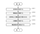
- FIG. 3 is a diagram showing the flow of manufacturing a separation membrane composite. It is a sectional view showing a separation device.
- FIG. 4 is a diagram showing the flow of separation of mixed substances;
- FIG. 1 is a cross-sectional view of a separation membrane composite 1 according to one embodiment of the present invention.
- FIG. 2 is a cross-sectional view showing an enlarged part of the separation membrane composite 1.
- the separation membrane composite 1 includes a ceramic support 11 (hereinafter also simply referred to as “support 11 ”) and a separation membrane 12 .
- support 11 hereinafter also simply referred to as “support 11 ”
- separation membrane 12 is drawn with a thick line.
- FIG. 2 the support 11 and the separation membrane 12 are hatched, and the thickness of the separation membrane 12 is drawn thicker than it actually is.
- the support 11 is a porous member that is permeable to gas and liquid.
- the support 11 has a plurality of through holes 111 (hereinafter referred to as It is a monolithic support provided with a "cell 111").
- the outer shape of the support 11 is, for example, substantially cylindrical.
- a plurality of cells 111 are arranged, for example, in a matrix in a cross section of the support 11 perpendicular to the longitudinal direction.
- a cross section perpendicular to the longitudinal direction of each cell 111 is, for example, substantially circular. Note that the substantially circular shape includes not only a perfect circle but also an ellipse and a distorted circle.
- each cell 111 is preferably a perfect circle, but does not necessarily have to be a perfect circle.
- the diameter of the cells 111 is drawn larger than it actually is, and the number of the cells 111 is drawn less than it actually is.
- a separation membrane 12 is arranged on the inner surface of each cell 111 .
- Separation membrane 12 is preferably provided so as to cover substantially the entire inner surface of each cell 111 .
- Support 11 is used to support separation membrane 12 .
- the length of the support 11 (that is, the length in the horizontal direction in FIG. 1) is, for example, 10 cm to 200 cm.
- the outer diameter of the support 11 is, for example, 0.5 cm to 30 cm.
- the distance between the central axes of adjacent cells 111 is, for example, 0.3 mm to 10 mm.
- the surface roughness (Ra) of the support 11 is, for example, 0.1 ⁇ m to 5.0 ⁇ m, preferably 0.2 ⁇ m to 2.0 ⁇ m.
- the shape of the support 11 may be, for example, a honeycomb shape, a flat plate shape, a tubular shape, a cylindrical shape, a columnar shape, a polygonal columnar shape, or the like. When the shape of the support 11 is tubular or cylindrical, the thickness of the support 11 is, for example, 0.1 mm to 10 mm.
- the support 11 has, for example, a multilayer structure in which a plurality of layers with different average pore diameters are stacked in the thickness direction near the inner surface of the cell 111 (that is, near the separation membrane 12).
- the support 11 includes a porous ceramic base material 31 (hereinafter also referred to simply as “base material 31”) and a porous ceramic additional layer 34 provided on the surface of the base material 31 ( Hereinafter, it is also simply referred to as “additional layer 34”).
- the additional layer 34 includes a porous intermediate layer 32 directly formed on the base material 31 and a porous surface layer 33 formed on the intermediate layer 32 . That is, the surface layer 33 is indirectly provided on the base material 31 via the intermediate layer 32 . Also, the intermediate layer 32 is provided between the base material 31 and the surface layer 33 .
- the surface layer 33 constitutes the inner surface of each cell 111 of the support 11 , and the separation membrane 12 is formed on the surface layer 33 .
- the thickness of the surface layer 33 is, for example, 1 ⁇ m to 100 ⁇ m.
- the thickness of the intermediate layer 32 is, for example, 100 ⁇ m to 500 ⁇ m.
- the intermediate layer 32 and the surface layer 33 may or may not be provided on the outer surface and longitudinal end surfaces of the support 11 .
- the materials of the support 11 are ceramics that have chemical stability in the process of forming the separation membrane 12 on the surface.
- the support 11 is made of a ceramic sintered body. Ceramic sintered bodies selected as the material for the support 11 include, for example, alumina, silica, mullite, zirconia, titania, yttria, silicon nitride, and silicon carbide. Preferably, support 11 is made of alumina, mullite, zirconia or titania.
- the materials of the substrate 31, intermediate layer 32 and surface layer 33 may be the same or different.
- the support 11 (that is, the base material 31, the intermediate layer 32 and the surface layer 33) contains, for example, an inorganic binder for binding the aggregate particles of the ceramic sintered body.
- an inorganic binder for binding the aggregate particles of the ceramic sintered body.
- At least one of titania, mullite, sinterable alumina, silica, glass frit, clay mineral, and sinterable cordierite can be used as the inorganic binder.
- the support 11 may contain an alkali metal and/or an alkaline earth metal.
- the alkali metals and alkaline earth metals are, for example, sodium (Na), potassium (K), calcium (Ca), magnesium (Mg) and the like.
- the average pore diameter of the surface layer 33 is smaller than the average pore diameter of the intermediate layer 32 and the average pore diameter of the substrate 31 . Also, the average pore diameter of the intermediate layer 32 is smaller than the average pore diameter of the substrate 31 . That is, the average pore diameter of the additional layer 34 is smaller than the average pore diameter of the substrate 31 .
- the average pore diameter of the substrate 31 is, for example, 1 ⁇ m or more and 70 ⁇ m or less.
- the average pore diameter of the intermediate layer 32 is, for example, 0.1 ⁇ m or more and 10 ⁇ m or less.
- the average pore diameter of the surface layer 33 is, for example, 0.005 ⁇ m or more and 2 ⁇ m or less.
- the average pore diameters of substrate 31, intermediate layer 32 and surface layer 33 can be measured, for example, by a mercury porosimeter, perm porometer or nanoperm porometer.
- the surface layer 33, the intermediate layer 32 and the base material 31 have substantially the same porosity.
- the surface layer 33, the intermediate layer 32 and the substrate 31 may have different porosities.
- the porosities of the surface layer 33, the intermediate layer 32 and the substrate 31 are, for example, 20% or more and 50% or less.
- the porosity of the base material 31 can be obtained by the following procedure. First, the pores of the base material 31 are filled with resin, and a polished cross section is produced by mechanical polishing. Subsequently, the polished cross section is observed with a laser microscope to obtain an image (hereinafter also referred to as a "polished cross section image"). Then, the polished cross-sectional image is binarized, the pore portion, the particle portion, and the inorganic binder portion are color-coded, and the ratio of the pore portion to the whole is taken as the porosity.
- the porosity of the intermediate layer 32 and the surface layer 33 can also be obtained by substantially the same procedure.
- the average particle diameter of the aggregate particles of the surface layer 33 (that is, the median diameter (D 50 ) in volume-based particle size distribution) is smaller than the average particle diameter of the intermediate layer 32 . Also, the average particle size of the aggregate particles of the intermediate layer 32 is smaller than the average particle size of the aggregate particles of the base material 31 .
- the average particle size of the aggregate particles of the base material 31, intermediate layer 32 and surface layer 33 can be measured, for example, by a laser diffraction method.
- FIG. 3 is an enlarged view showing a part of the polished cross-sectional image of the substrate 31.
- the base material 31 includes a plurality of coarse grains 311 (ie, coarse crystal grains) and a plurality of fine grains 312 (ie, fine crystal grains) as aggregate particles.
- Each of the plurality of coarse grains 311 is a ceramic grain having a grain size of 30 ⁇ m or more.
- the average aspect ratio of the plurality of coarse grains 311 is 1.5 or more and 2 or less.
- Each of the plurality of fine particles 312 is a ceramic particle with a particle size of 1 ⁇ m or more and less than 30 ⁇ m.
- the ratio of the number of the plurality of coarse particles 311 to the number of the plurality of fine particles 312 (hereinafter also referred to as "coarse particle ratio") is 0.05 or more and 0.3 or less.
- the plurality of coarse grains 311 and the plurality of fine grains 312 are preferably particles of alumina, mullite, zirconia or titania, as described above. In this embodiment, the plurality of coarse particles 311 and the plurality of fine particles 312 are alumina particles.
- the particle size of the aggregate particles (that is, coarse particles 311 and fine particles 312) of the base material 31 can be obtained by the following procedure. First, the pores of the base material 31 are filled with resin, and a polished cross section is produced by mechanical polishing. Subsequently, in an image obtained by observing the polished cross section with a laser microscope (that is, a polished cross section image), one aggregate particle is focused on, and two parallel straight lines are drawn to circumscribe the aggregate particle. Next, while maintaining the state in which the two straight lines are circumscribed by the aggregate particles, the direction of the two straight lines is changed, and the distance between the two straight lines is changed in the direction in which the distance between the two straight lines is maximized. Obtained as the major diameter of the aggregate particles.
- Aggregate particles with a major axis of 30 ⁇ m or more are called coarse particles 311
- aggregate particles with a major axis of 1 ⁇ m or more and less than 30 ⁇ m are called fine particles 312 .
- Particles with a major axis of less than 1 ⁇ m are not included in the coarse particles 311 and fine particles 312 .
- the average aspect ratio of the plurality of coarse grains 311 of the base material 31 can be obtained by the following procedure. First, for each of the 30 coarse grains 311 in the polished cross-sectional image, the length in the direction perpendicular to the major axis (that is, the minor axis) is obtained, and the value obtained by dividing the major axis by the minor axis is the aspect of each coarse particle 311. obtained as a ratio. Then, the arithmetic mean of the aspect ratios of the 30 coarse grains 311 is obtained as the average aspect ratio of the plurality of coarse grains 311 .
- the coarse grain ratio can be obtained by the following procedure. First, the polished cross-sectional image described above is obtained at a magnification of 1000 times. Subsequently, the number of coarse particles 311 and the number of fine particles 312 in the polished cross-sectional image are visually counted. At this time, if the number of coarse particles 311 included in the polished cross-sectional image is less than 50, the position on the substrate 31 is changed, the polished cross-sectional image is acquired again, and the number of coarse particles 311 and fine particles 312 is visually observed. count in Then, by dividing the obtained number of coarse particles 311 by the number of fine particles 312, the coarse particle ratio is obtained.
- the base material 31 since coarse particles 311 are included as aggregate particles, the gaps between the aggregate particles are increased, so that the permeation resistance of the base material 31 can be reduced. On the other hand, since the sinterability of the aggregate particles is lowered and the necking (bonding) between the aggregate particles is weakened, the mechanical strength (hereinafter also simply referred to as "strength") of the base material 31 is lowered. In addition, since the base material 31 contains fine particles 312 as aggregate particles, the sinterability of the aggregate particles is improved and the necking between the aggregate particles is strengthened, so that the strength of the base material 31 is increased. be able to. On the other hand, the permeation resistance of the substrate 31 increases because the gaps between the aggregate particles are reduced. As described above, in the base material 31, by setting the coarse grain ratio to 0.05 or more and 0.3 or more, both reduction in permeation resistance and securing of strength of the base material 31 can be achieved.
- the base material 31 by setting the average aspect ratio of the plurality of coarse grains 311 to 1.5 or more, the gaps between the adjacent coarse grains 311 are compared to when the average aspect ratio is less than 1.5. Since it becomes a straight line (that is, because the curvature of the gap is suppressed), the permeation resistance of the base material 31 can be reduced. In addition, by setting the average aspect ratio of the plurality of coarse grains 311 to 2 or less, a relatively large contact point between adjacent coarse grains 311 is ensured, thereby suppressing weakening of necking between aggregate grains. . Therefore, in the base material 31, it is possible to preferably achieve both reduction in permeation resistance and securing of strength.
- the base material 31 includes an inorganic binder 313 that binds the plurality of coarse particles 311 and/or the plurality of fine particles 312 together.
- the inorganic bonding material 313 is hatched in parallel to facilitate understanding of the drawing.
- the inorganic bonding material 313 is, for example, translucent.
- the inorganic binder 313 may bind the coarse particles 311 together, may bind the coarse particles 311 and the fine particles 312 together, or may bind the fine particles 312 together.
- the inorganic binder 313 is, for example, glass frit or titania. In the base material 31, since the necking between the aggregate particles is reinforced by the inorganic binder 313, the strength of the base material 31 is improved.
- the fine particles 312 are preferably surrounded by the inorganic binder 313 .
- the grain boundaries around the fine grains 312 are reduced, and the occurrence of cracks caused by the grain boundaries is suppressed.
- the number of the particles 312 surrounded by the inorganic bonding material 313 over the entire circumference of the plurality of particles 312 is of 5% or more.
- the amount of the inorganic binder 313 increases, the gaps between the aggregate particles are filled with the inorganic binder 313 and the permeation resistance of the base material 31 increases.
- the number of the particles 312 surrounded by the inorganic bonding material 313 is 55% of the number of the particles 312 among the particles 312. The following are preferred.
- the ratio of the number of fine particles 312 surrounded by the inorganic binder 313 to the number of the plurality of fine particles 312 is also referred to as the "enclosed fine particle ratio”.
- FIG. 4 like FIG. 3, is a diagram showing an enlarged part of the polished cross-sectional image of the substrate 31.
- FIG. 4 among the plurality of fine particles 312 , the fine particles 312 surrounded by the inorganic binder 313 over the entire periphery are hatched.
- the fine grains 312 surrounded by the inorganic binder 313 all around are the fine grains 312 that are entirely located inside the outer edge of the inorganic binder 313 and away from the outer edge. means. Note that when at least a part of the fine particles 312 is located outside the outer edge of the inorganic binder 313, the fine particles 312 are not surrounded by the inorganic binder 313 all around. be judged.
- the fine granule 312 is surrounded by the inorganic binder 313 . It is determined that the entire circumference is not surrounded.
- the separation membrane 12 shown in FIG. 2 is formed on the inner surface of each cell 111 (ie, on the surface layer 33 of the additional layer 34) and covers substantially the entire inner surface.
- the separation membrane 12 is a porous membrane having fine pores.
- the separation membrane 12 separates a specific substance from a mixed substance in which multiple types of substances are mixed.
- separation membrane 12 is substantially cylindrical.
- the separation membrane 12 is preferably an inorganic membrane made of an inorganic material, more preferably a zeolite membrane. That is, the separation membrane composite 1 is preferably an inorganic membrane composite, more preferably a zeolite membrane composite.
- the zeolite membrane is at least one in which zeolite is formed in the form of a membrane on the surface of the support 11, and does not include an organic membrane in which zeolite particles are simply dispersed.
- the separation membrane 12 is a zeolite membrane. Separation membrane 12 may be a zeolite membrane containing two or more types of zeolites having different structures and compositions.
- the thickness of the separation membrane 12 is, for example, 0.05 ⁇ m or more and 50 ⁇ m or less, preferably 0.1 ⁇ m or more and 20 ⁇ m or less, and more preferably 0.5 ⁇ m or more and 10 ⁇ m or less. Separation performance is improved by increasing the thickness of the separation membrane 12 . When the separation membrane 12 is thinned, the permeation rate increases.
- the surface roughness (Ra) of the separation membrane 12 is, for example, 5 ⁇ m or less, preferably 2 ⁇ m or less, more preferably 1 ⁇ m or less, and even more preferably 0.5 ⁇ m or less.
- the pore diameter of the separation membrane 12 is, for example, 0.2 nm to 1 nm. The pore size of the separation membrane 12 is smaller than the average pore size of the surface layer 33 of the support 11 .
- the minor diameter of the n-membered ring pores is the pore diameter of the separation membrane 12 .
- the minor diameter of the n-membered ring pore having the largest minor diameter is taken as the pore diameter of the separation membrane 12 .
- the n-membered ring is a portion in which the number of oxygen atoms constituting the pore-forming skeleton is n, and each oxygen atom is bonded to a T atom described later to form a ring structure.
- n-membered ring refers to a ring that forms a through hole (channel), and does not include a ring that does not form a through hole.
- An n-membered ring pore is a pore formed by an n-membered ring.
- the maximum number of ring members of the zeolite constituting the separation membrane 12 is preferably 8 or less (eg, 6 or 8).
- the pore diameter of the separation membrane 12 is uniquely determined by the framework structure of the zeolite. iza-structure. It can be obtained from the values disclosed in org/databases/>.
- the type of zeolite that constitutes the separation membrane 12 is not particularly limited. X type, Y type), GIS type, IHW type, LEV type, LTA type, LTJ type, MEL type, MFI type, MOR type, PAU type, RHO type, SOD type, SAT type zeolite, etc. .
- the zeolite is an eight-membered ring zeolite, for example, AEI type, AFN type, AFV type, AFX type, CHA type, DDR type, ERI type, ETL type, GIS type, IHW type, LEV type, LTA type, LTJ type, RHO type, SAT type zeolite, and the like.
- the type of zeolite forming separation membrane 12 is DDR type zeolite.
- the zeolite that constitutes the separation membrane 12 contains, for example, silicon (Si), aluminum (Al) and phosphorus (P) as T atoms (that is, atoms located at the center of the oxygen tetrahedron (TO 4 ) that constitutes the zeolite).
- T atoms that is, atoms located at the center of the oxygen tetrahedron (TO 4 ) that constitutes the zeolite.
- the zeolite that constitutes the separation membrane 12 includes zeolite in which T atoms are composed of only Si or Si and Al, ALPO-type zeolite in which T atoms are composed of Al and P, and T atoms of which are composed of Si, Al, and P.
- SAPO-type zeolite SAPO-type zeolite, MAPSO-type zeolite in which T atoms are composed of magnesium (Mg), Si, Al, and P, and ZnAPSO-type zeolite in which T atoms are composed of zinc (Zn), Si, Al, and P, and the like. Some of the T atoms may be substituted with other elements.
- the zeolite forming the separation membrane 12 may contain an alkali metal.
- the alkali metal is, for example, sodium (Na) or potassium (K).
- the Si/Al ratio in the zeolite forming the separation membrane 12 is, for example, 1 or more and 100,000 or less.
- the Si/Al ratio is the molar ratio of Si element to Al element contained in the zeolite constituting separation membrane 12 .
- the Si/Al ratio is preferably 5 or more, more preferably 20 or more, and still more preferably 100 or more.
- the Si/Al ratio can be adjusted by adjusting the mixing ratio of the Si source and the Al source in the raw material solution, which will be described later.
- the separation membrane composite 1 one of the intermediate layer 32 and the surface layer 33 of the additional layer 34 may be omitted.
- the additional layer 34 may have a laminated structure of three or more layers.
- the additional layer 34 may be omitted and the substrate 31 may function alone as the support 11 . In this case, separation membrane 12 is provided directly on the surface of substrate 31 .
- the support 11 is formed (Step S11). Specifically, first, ceramic particles, an inorganic binder, water, a dispersant, a thickener, and the like are kneaded to prepare a clay that is a raw material for the base material 31 of the support 11 . Subsequently, the clay is molded by extrusion molding or the like to form a monolithic molded body. Next, the base material 31 is obtained by baking the molded body.
- ceramic particles alumina particles in the present embodiment
- the ceramic particles include raw material coarse particles having a large particle size and raw material fine particles having a small particle size.
- the content of the raw material coarse particles in the ceramic particles (that is, the value expressed as a percentage by dividing the mass of the raw material coarse particles by the total mass of the raw material coarse particles and the raw material fine particles) is, for example, 5% by mass to 30%. % by mass.
- D 10 is 60 ⁇ m to 100 ⁇ m
- D 50 that is, average particle diameter
- D 90 is 200 ⁇ m to 300 ⁇ m
- the D 10 in the volume-based particle size distribution of the raw material fine particles is 3 ⁇ m to 10 ⁇ m
- the D 50 that is, the average particle size
- the D 90 is 60 ⁇ m to 160 ⁇ m.
- the sintering temperature of the above compact is, for example, 500° C. to 1500° C., and is 1250° C. in this embodiment.
- the firing time of the above compact is, for example, 1 hour to 100 hours, and is 2 hours in the present embodiment.
- the intermediate layer 32 is formed on the inner side surfaces of the plurality of through holes of the base material 31 (that is, the through holes to become the cells 111), and the surface layer 33 is formed on the intermediate layer 32.
- the support 11 is formed.
- Formation of the intermediate layer 32 and the surface layer 33 is performed by, for example, a filtration film forming method.
- a filtration film forming method In forming the intermediate layer 32, first, aggregate particles, an organic binder, a pH adjuster, a surfactant, etc. for the intermediate layer 32 are added to water, mixed, and diluted with a predetermined amount of water to prepare a slurry.
- the slurry is caused to flow into the plurality of through-holes of the base material 31 to form a film of aggregate particles of the intermediate layer 32 on the inner surfaces of the plurality of through-holes.
- the intermediate layer 32 is formed by firing the film together with the substrate 31 . Formation of the surface layer 33 is substantially the same as formation of the intermediate layer 32 .
- step S12 seed crystals used for forming the separation membrane 12 are produced and prepared (step S12).
- a raw material solution of seed crystals is prepared by dissolving or dispersing a raw material such as a Si source and a structure-directing agent (hereinafter also referred to as "SDA") in a solvent.
- SDA structure-directing agent
- the raw material solution is hydrothermally synthesized, and the obtained crystals are washed and dried to obtain zeolite powder.
- the zeolite powder may be used as it is as a seed crystal, or the seed crystal may be obtained by processing the powder by pulverization or the like.
- the seed crystal formation in step S12 may be performed in parallel with the formation of support 11 in step S11 described above, or may be performed prior to the formation of support 11 .
- a dispersion liquid in which seed crystals are dispersed in a solvent for example, water or alcohol such as ethanol
- a solvent for example, water or alcohol such as ethanol
- the support 11 is placed on a base so that the longitudinal direction is substantially parallel to the direction of gravity, and the dispersion liquid is poured from the upper opening of each cell 111, so that the seed crystals in the dispersion liquid It adheres to the inner surface of 111 (step S13). Specifically, the seed crystals adhere to the surface of the additional layer 34 of the support 11 .
- the dispersion liquid poured into the cell 111 is discharged from the lower opening of the cell 111 .
- step S13 is repeated multiple times (for example, 2 to 10 times). More preferably, the support 11 is turned upside down while step S13 is being performed a plurality of times. As a result, a seed crystal-attached support in which seed crystals are uniformly attached to the inner surface of each cell 111 is produced. Note that the seed crystal may be adhered to the inner surface of the cell 111 by another method.
- the raw material solution is prepared, for example, by dissolving the Si source, SDA, etc. in a solvent.
- a solvent for example, water or alcohol such as ethanol is used.
- the SDA contained in the raw material solution is, for example, an organic substance.
- SDA for example, 1-adamantanamine can be used.
- the separation membrane 12 is formed on the inner surface of each cell 111 of the support 11 (that is, on the additional layer 34) (step S14).
- the temperature during hydrothermal synthesis is preferably 120°C to 200°C, for example 160°C.
- the hydrothermal synthesis time is preferably 5 hours to 100 hours, for example 30 hours.
- the support 11 and separation membrane 12 are washed with pure water.
- the washed support 11 and separation membrane 12 are dried at 80° C., for example.
- the separation membrane 12 is heat-treated (that is, baked) to almost completely burn off the SDA in the separation membrane 12 and remove the micropores in the separation membrane 12. pass through.
- the separation membrane composite 1 described above is obtained (step S15).
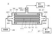
- FIG. 6 is a cross-sectional view showing the separation device 2. As shown in FIG. In FIG. 6, the cross section of the separation membrane composite 1 is simplified and conceptually shown for easy understanding of the drawing.
- FIG. 7 is a diagram showing the flow of separation of the mixed substance by the separation device 2. As shown in FIG.
- a mixed substance containing multiple types of fluids that is, gas or liquid
- a highly permeable substance in the mixed substance is allowed to permeate the separation membrane composite 1.
- separated from the mixture by Separation in the separation device 2 may be performed, for example, for the purpose of extracting a highly permeable substance (hereinafter also referred to as a "highly permeable substance”) from a mixed substance, and a low-permeable substance (hereinafter also referred to as a " (also referred to as "low-permeability substances”).
- the mixed substance (that is, mixed fluid) may be a mixed gas containing multiple types of gas, a mixed liquid containing multiple types of liquid, or a gas-liquid two-phase mixture containing both gas and liquid. It may be a fluid.
- Mixed substances include, for example, hydrogen (H 2 ), helium (He), nitrogen (N 2 ), oxygen (O 2 ), water (H 2 O), carbon monoxide (CO), carbon dioxide (CO 2 ), Nitrogen oxides, ammonia (NH 3 ), sulfur oxides, hydrogen sulfide (H 2 S), sulfur fluoride, mercury (Hg), arsine (AsH 3 ), hydrogen cyanide (HCN), carbonyl sulfide (COS), C1- Contains one or more of C8 hydrocarbons, organic acids, alcohols, mercaptans, esters, ethers, ketones and aldehydes.
- the highly permeable substances mentioned above are, for example, one or more of CO2 , NH3 and H2O . Note that the mixed substance and the highly permeable substance may be substances other than these substances.
- Nitrogen oxides are compounds of nitrogen and oxygen. Nitrogen oxides mentioned above include, for example, nitric oxide (NO), nitrogen dioxide (NO 2 ), nitrous oxide (also referred to as dinitrogen monoxide) (N 2 O), dinitrogen trioxide (N 2 O 3 ), dinitrogen tetroxide (N 2 O 4 ), dinitrogen pentoxide (N 2 O 5 ), and other substances called NO x (nox).
- NO nitric oxide
- NO 2 nitrogen dioxide
- NO 2 O nitrous oxide
- N 2 O 3 dinitrogen trioxide
- N 2 O 4 dinitrogen tetroxide
- N 2 O 5 dinitrogen pentoxide
- Sulfur oxides are compounds of sulfur and oxygen.
- the sulfur oxides mentioned above are substances called SOx (socks) such as sulfur dioxide (SO 2 ) and sulfur trioxide (SO 3 ).
- Sulfur fluoride is a compound of fluorine and sulfur.
- C1-C8 hydrocarbons are hydrocarbons having 1 or more and 8 or less carbons.
- the C3-C8 hydrocarbons may be straight chain compounds, side chain compounds and cyclic compounds.
- C2 to C8 hydrocarbons include saturated hydrocarbons (that is, those in which double bonds and triple bonds are not present in the molecule), unsaturated hydrocarbons (that is, those in which double bonds and/or triple bonds are present in the molecule). existing within).
- the organic acids mentioned above are carboxylic acids, sulfonic acids, and the like.
- Carboxylic acids are, for example, formic acid (CH 2 O 2 ), acetic acid (C 2 H 4 O 2 ), oxalic acid (C 2 H 2 O 4 ), acrylic acid (C 3 H 4 O 2 ) or benzoic acid (C 6 H 5 COOH) and the like.
- Sulfonic acid is, for example, ethanesulfonic acid (C 2 H 6 O 3 S).
- the organic acid may be a chain compound or a cyclic compound.
- the aforementioned alcohols are, for example, methanol (CH 3 OH), ethanol (C 2 H 5 OH), isopropanol (2-propanol) (CH 3 CH(OH)CH 3 ), ethylene glycol (CH 2 (OH)CH 2 ( OH)) or butanol ( C4H9OH ), and the like.
- Mercaptans are organic compounds having hydrogenated sulfur (SH) at the end, and are also called thiols or thioalcohols.
- the mercaptans mentioned above are, for example, methyl mercaptan (CH 3 SH), ethyl mercaptan (C 2 H 5 SH) or 1-propanethiol (C 3 H 7 SH).
- esters are, for example, formate esters or acetate esters.
- ethers are, for example, dimethyl ether ((CH 3 ) 2 O), methyl ethyl ether (C 2 H 5 OCH 3 ) or diethyl ether ((C 2 H 5 ) 2 O).
- ketones mentioned above are, for example , acetone (( CH3 ) 2CO ), methyl ethyl ketone ( C2H5COCH3 ) or diethylketone (( C2H5 ) 2CO ).
- aldehydes mentioned above are, for example, acetaldehyde (CH 3 CHO), propionaldehyde (C 2 H 5 CHO) or butanal (butyraldehyde) (C 3 H 7 CHO).
- the separation device 2 includes a separation membrane composite 1, a sealing portion 21, a housing 22, and two sealing members 23. Separation membrane composite 1 , sealing portion 21 and sealing member 23 are accommodated in housing 22 .
- the separation membrane 12 of the separation membrane composite 1 is hatched.
- the internal space of the housing 22 is a closed space isolated from the surrounding space of the housing 22 .
- a supply portion 26 , a first recovery portion 27 and a second recovery portion 28 are connected to the housing 22 .
- the sealing portions 21 are attached to both ends of the support 11 in the longitudinal direction (that is, the left-right direction in FIG. It is a member that covers and seals a part of the outer surface of the.
- the sealing portion 21 is a glass seal with a thickness of 10 ⁇ m to 50 ⁇ m.
- the material and shape of the sealing portion 21 may be changed as appropriate. Since the sealing portion 21 is provided with a plurality of openings that overlap with the plurality of cells 111 of the support 11 , both longitudinal ends of each cell 111 are not covered with the sealing portion 21 . Therefore, fluid can flow in and out of the cell 111 from both ends.
- the housing 22 is a substantially cylindrical cylindrical member.
- the housing 22 is made of stainless steel or carbon steel, for example.
- the longitudinal direction of the housing 22 is substantially parallel to the longitudinal direction of the separation membrane composite 1 .
- a supply port 221 is provided at one longitudinal end of the housing 22 (that is, the left end in FIG. 6), and a first discharge port 222 is provided at the other end.
- the supply portion 26 is connected to the supply port 221 .
- the first recovery section 27 is connected to the first discharge port 222 .
- a second discharge port 223 is provided on the side surface of the housing 22 .
- the second recovery section 28 is connected to the second discharge port 223 . Note that the shape and material of the housing 22 may be changed in various ways.
- the two sealing members 23 are arranged between the outer surface of the separation membrane composite 1 and the inner surface of the housing 22 in the vicinity of both ends of the separation membrane composite 1 in the longitudinal direction.
- Each seal member 23 is a substantially annular member made of a material impermeable to gas and liquid.
- the sealing member 23 is, for example, an O-ring or packing made of flexible resin.
- the sealing member 23 is in close contact with the outer surface of the separation membrane composite 1 and the inner surface of the housing 22 over the entire circumference of the separation membrane composite 1 .
- the sealing member 23 is closely attached to the outer surface of the sealing portion 21 and indirectly to the outer surface of the separation membrane composite 1 via the sealing portion 21 .
- seal member 23 may be in direct contact with the outer surface of the separation membrane composite 1 . Seals are provided between each sealing member 23 and the outer surface of the separation membrane composite 1 or the sealing portion 21 and between each sealing member 23 and the inner surface of the housing 22 to prevent the passage of gas and liquid. practically impossible.
- the material of the sealing member 23 may be carbon, metal, or other inorganic materials other than resin.
- the supply unit 26 supplies the mixed substance to the internal space of the housing 22 via the supply port 221 .
- the supply unit 26 includes, for example, a pumping mechanism such as a blower or a pump that pumps the mixture toward the housing 22 .
- the pumping mechanism includes, for example, a temperature control section and a pressure control section for controlling the temperature and pressure of the mixed substance supplied to the housing 22, respectively.
- the first recovery section 27 and the second recovery section 28 are provided with, for example, a storage container that stores the substance drawn out from the housing 22, or a blower or a pump that transfers the substance.
- the separation membrane composite 1 is prepared (Fig. 7: step S21). Specifically, the separation membrane composite 1 is attached inside the housing 22 . Subsequently, the supply unit 26 supplies a mixed substance containing a plurality of types of substances with different permeability to the separation membrane 12 into the housing 22 as indicated by an arrow 251 .
- the mixed substance is a mixed liquid in which multiple kinds of liquids are mixed.
- the main components of the liquid mixture are, for example, water and ethanol.
- the mixed liquid may contain liquids other than water and ethanol.
- the mixed substance supplied from the supply part 26 to the housing 22 is introduced into each cell 111 of the support 11 from the left end of the separation membrane composite 1 in the figure.
- a highly permeable substance which is a highly permeable substance in the mixed substance, permeates the separation membrane 12 provided on the inner surface of each cell 111 and the support 11 and is led out from the outer surface of the support 11. be.
- the highly permeable substance eg, water
- the low-permeable substance eg, ethanol
- permeable substances Substances drawn out from the outer surface of the support 11 (hereinafter referred to as “permeable substances”) are guided to the second collection section 28 via the second discharge port 223 as indicated by an arrow 253, Collected by the second collecting unit 28 .
- the permeable substance may include a low-permeable substance that has permeated the separation membrane 12 in addition to the above-described high-permeable substance.
- non-permeate substances substances other than substances that have permeated the separation membrane 12 and the support 11 (hereinafter referred to as “non-permeate substances”) are passed through each cell 111 of the support 11 from left to right in the drawing. , and is recovered by the first recovery section 27 via the first discharge port 222 as indicated by an arrow 252 .
- the non-permeable substance may include a highly permeable substance that has not permeated through the separation membrane 12, in addition to the low-permeable substance described above.
- the non-permeable substance recovered by the first recovery section 27 may be circulated to the supply section 26 and supplied again into the housing 22, for example.
- Table 1 shows information about the raw material of the substrate 31 of the separation membrane composite 1.
- Table 2 shows the relationship between the physical properties of the particles of the substrate 31 of the separation membrane composite 1 (that is, the physical properties of the sintered particles) and the permeation resistance and strength.
- Example 1 the separation membrane composite 1 was produced by the same production method as in steps S11 to S15 described above.
- step S11 10 parts by mass of glass, which is an inorganic binder, is added to 100 parts by mass of alumina particles, which are aggregate particles, in the preparation of the clay that is the raw material of the base material 31 .
- the content of raw material coarse particles in the alumina particles (that is, raw material coarse particles and raw material fine particles) is 30% by mass.
- the D50 of the raw material granules is 40 ⁇ m.
- the raw material coarse grains have a D50 of 90 ⁇ m.
- the sintering temperature and sintering time of the compact to be the base material 31 were 1250° C. and 2 hours.
- the seed crystals produced in step S12 are DDR type zeolite crystals.
- the separation membrane 12 formed in each cell 111 in step S14 is a DDR type zeolite membrane.
- the coarse particle ratio, the average aspect ratio of the coarse particles 311, and the enclosed fine particle ratio, which are the physical properties of the particles of the substrate 31, were 0.293 and 1.9, respectively. , and 10%.
- Example 1 the water permeation amount of the separation membrane composite 1 was measured and the permeation resistance was evaluated as follows. First, the separation membrane composite 1 was attached inside the housing 22 of the separation device 2 described above, and a mixture of water and ethanol was supplied into the housing 22 from the supply portion 26 . In the mixed liquid, the weight ratio of water and ethanol is 50:50. The temperature of the liquid mixture supplied into the housing 22 was set to 60°C. Then, the mixed liquid is separated by the pervaporation method (so-called PV method) with the pressure on the permeate side, which is the pressure on the secondary side of the separation membrane 12, set to 50 torr (about 6.666 kPa). The amount of permeate that permeated through (ie, permeation) was measured.
- PV method pervaporation method
- the density of the permeable substance was measured with a density hydrometer to determine the ratio of water to ethanol in the permeable substance (hereinafter also referred to as "water/ethanol ratio"). After that, the amount of water that permeated through the separation membrane composite 1 (that is, the water permeation amount) was determined based on the permeation amount and the water/ethanol ratio described above.
- Example 1 the water flowed into each cell 111 of the separation membrane composite 1 was pressurized, and the internal pressure breaking strength (that is, pressure resistance) at which the separation membrane composite 1 was broken was measured.
- the strength of membrane composite 1 was evaluated.
- Table 1 when the compressive strength is 20 MPa or more, " ⁇ " indicating that the strength is suitably high is described in the strength column.
- the compressive strength is 18 MPa or more and less than 20 MPa
- “ ⁇ ” indicating that the strength is relatively high is entered in the strength column.
- the compressive strength is less than 18 MPa
- “x” indicating that the strength is low is entered in the strength column.
- the strength was ⁇ .
- step S11 20 parts by mass of an inorganic binder is added to 100 parts by mass of alumina particles, the content of raw material coarse particles in the alumina particles is 5% by mass, and the content of raw material fine particles is It is the same as Example 1 except that the D50 is 20 ⁇ m and the D50 of the raw material coarse particles is 60 ⁇ m.
- the coarse grain ratio was 0.052
- the average aspect ratio of the coarse grains 311 was 1.9
- the ratio of surrounded fine grains was 40%. there were.
- the water permeation resistance was ⁇ and the strength was ⁇ .
- Example 3 in step S11, 18 parts by mass of an inorganic binder is added to 100 parts by mass of alumina particles, and the content of raw material coarse particles in the alumina particles is 20% by mass. , is the same as in Example 1.
- the coarse particle ratio was 0.295
- the average aspect ratio of the coarse particles 311 was 1.5
- the ratio of the enclosed fine particles was 31%. there were.
- the water permeation resistance was ⁇ and the strength was ⁇ .
- Example 4 is the same as Example 2, except that 15 parts by mass of an inorganic binder is added to 100 parts by mass of alumina particles in step S11.
- the coarse grain ratio was 0.055
- the average aspect ratio of the coarse grains 311 was 1.5
- the ratio of surrounded fine grains was 20%. there were.
- the water permeation resistance was ⁇ and the strength was ⁇ .
- Example 5 is the same as Example 3, except that 3 parts by mass of an inorganic binder is added to 100 parts by mass of alumina particles in step S11.
- the coarse grain ratio was 0.295
- the average aspect ratio of the coarse grains 311 was 1.9
- the ratio of surrounded fine grains was 5%. there were.
- the water permeation resistance was ⁇ and the strength was ⁇ .
- Example 6 is the same as Example 2, except that 25 parts by mass of an inorganic binder is added to 100 parts by mass of alumina particles in step S11.
- the coarse grain ratio was 0.055
- the average aspect ratio of the coarse grains 311 was 1.5
- the ratio of surrounded fine grains was 55%. there were.
- the water permeation resistance was ⁇ and the strength was ⁇ .
- step S11 15 parts by mass of an inorganic binder is added to 100 parts by mass of alumina particles, the content of raw material coarse particles in the alumina particles is 40% by mass, and the raw material Same as Example 1 except that the D50 for the coarse grain is 120 ⁇ m.
- the coarse particle ratio was 0.343
- the average aspect ratio of the coarse particles 311 was 1.9
- the ratio of the enclosed fine particles was 21%. there were.
- the water permeation resistance was ⁇ and the strength was ⁇ .
- Comparative Example 2 is the same as Example 4, except that the content of raw material coarse particles in the alumina particles is 0% by mass (that is, no raw material coarse particles are included) in step S11.
- the coarse particle ratio was 0.025
- the average aspect ratio of the coarse particles 311 was 1.9
- the ratio of the enclosed fine particles was 20%. there were.
- the water permeation resistance was x and the strength was ⁇ .
- Comparative Example 3 is the same as Example 1, except that the content of raw material coarse particles in the alumina particles is 20% by mass in step S11.
- the coarse particle ratio was 0.297
- the average aspect ratio of the coarse particles 311 was 1.2
- the ratio of surrounded fine particles was 15%. there were.
- the water permeation resistance was x and the strength was ⁇ .
- Comparative Example 4 is the same as Comparative Example 3, except that 15 parts by mass of an inorganic binder is added to 100 parts by mass of alumina particles in step S11.
- the coarse grain ratio was 0.296
- the average aspect ratio of the coarse grains 311 was 2.5
- the ratio of surrounded fine grains was 23%. there were.
- the water permeation resistance was ⁇ and the strength was ⁇ .
- Comparative Example 5 is the same as Example 4, except that the content of raw material coarse particles in the alumina particles in step S11 is 7% by mass.
- the coarse grain ratio was 0.063
- the average aspect ratio of the coarse grains 311 was 2.5
- the ratio of surrounded fine grains was 20%. there were.
- the water permeation resistance was ⁇ and the strength was ⁇ .
- step S11 10 parts by mass of an inorganic binder is added to 100 parts by mass of alumina particles, and the content of raw material coarse particles in the alumina particles is 3% by mass.
- Comparative Example 5 In the substrate 31 of the separation membrane composite 1 produced in Comparative Example 6, the coarse grain ratio was 0.053, the average aspect ratio of the coarse grains 311 was 1.2, and the ratio of surrounded fine grains was 15%. there were.
- the water permeation resistance was x and the strength was ⁇ .
- the coarse grain ratio is set to 0.05 or more and 0.3 or less from the viewpoint of achieving both a reduction in the permeation resistance of the base material 31 and ensuring strength. preferably. Further, when comparing Examples 1 to 6 with Comparative Examples 3 to 6, from the viewpoint of achieving both reduction in permeation resistance of the base material 31 and ensuring strength, the average aspect ratio of the coarse grains 311 is 1.5 or more and 2 or less is preferable.
- the ratio of the enclosed fine grains is greater than 5%.
- the ratio of the enclosed fine particles is preferably less than 55%.
- the porous ceramic base material (that is, the base material 31) used to support the separation membrane 12 includes a plurality of coarse particles 311, each of which is ceramic particles having a particle size of 30 ⁇ m or more. and a plurality of fine particles 312 which are ceramic particles having a particle size of 1 ⁇ m or more and less than 30 ⁇ m.
- the ratio of the number of coarse particles 311 to the number of fine particles 312 (that is, the coarse particle ratio) is 0.05 or more and 0.3 or less.
- the average aspect ratio of the plurality of coarse grains 311 is 1.5 or more and 2 or less.
- the base material 31 preferably further includes an inorganic binder 313 that binds the plurality of coarse particles 311 and/or the plurality of fine particles 312 together. Further, the number of the particles 312 surrounded by the inorganic binder 313 over the entire circumference of the plurality of particles 312 is preferably greater than 5% and less than 55% of the number of the plurality of particles 312. . Thereby, the strength of the base material 31 can be further improved, and the transmission resistance can be further reduced.
- the porosity of the substrate 31 is preferably 20% or more and 50% or less. As a result, it is possible to achieve both a reduction in the permeation resistance of the base material 31 and ensuring the strength of the base material 31 more preferably.
- the plurality of coarse grains 311 and the plurality of fine grains 312 are preferably particles of alumina, mullite, zirconia or titania. As a result, when the separation membrane 12 is directly provided on the substrate 31, the bonding strength between the substrate 31 and the separation membrane 12 can be increased, so that the separation membrane 12 can be stably supported. .
- the base material 31 preferably has a columnar shape extending in the longitudinal direction, and the plurality of cells 111 penetrate in the longitudinal direction.
- the base material 31 preferably has a columnar shape extending in the longitudinal direction, and the plurality of cells 111 penetrate in the longitudinal direction.
- the porous ceramic support used to support the separation membrane 12 (that is, the support 11) is provided on the substrate 31 described above and on the surface of the substrate 31 and has an average pore diameter smaller than that of the substrate 31. and a porous ceramic add-on layer (ie, add-on layer 34) having an average pore size.
- a porous ceramic add-on layer ie, add-on layer 34
- the separation membrane composite 1 described above comprises the substrate 31 or the support 11 , and the separation membrane 12 provided on the surface of the substrate 31 or on the additional layer 34 of the support 11 . As a result, both reduction in permeation resistance and securing of strength of the separation membrane composite 1 can be achieved.
- the separation membrane 12 is preferably a zeolite membrane.
- the separation membrane 12 By configuring the separation membrane 12 with zeolite crystals having uniform pore diameters, selective permeation of highly permeable substances can be suitably realized. As a result, the highly permeable substance can be efficiently separated from the mixed substance.
- the zeolite constituting the zeolite membrane has a maximum number of ring members of 8 or less.
- a highly permeable substance having a relatively small molecular diameter can be realized more favorably.
- highly permeable substances can be more efficiently separated from mixed substances.
- the porosity of the base material 31 may be less than 20% or greater than 50%.
- the ratio of the surrounded fine particles in the base material 31 may be 5% or less, or may be 55% or more.
- the maximum number of ring members of the zeolite constituting the separation membrane 12, which is a zeolite membrane, may be greater than eight.
- the separation membrane 12 is not limited to a zeolite membrane, and may be an inorganic membrane such as a silica membrane or a carbon membrane, an organic membrane such as a polyimide membrane or a silicone membrane, or a metal organic structure ( MOF) film.
- the separation membrane composite 1 may further include a functional membrane or a protective membrane laminated on the separation membrane 12 .
- a functional film or protective film may be a zeolite film, an inorganic film other than the zeolite film, an organic film, or an MOF film.
- the separation membrane composite 1 does not necessarily have to be manufactured by the manufacturing method described above (steps S11 to S15), and may be manufactured by various other manufacturing methods.
- the separation membrane composite 1 may be used for separating mixed substances or for other purposes in various devices having different structures from the separation device 2 described above.
- the ceramic substrate and ceramic support of the present invention can be used, for example, for supporting zeolite membranes that can be used as separation membranes.
- the separation membrane composite of the present invention can be used as a separation membrane for various substances, an adsorption membrane for various substances, and the like.
Landscapes
- Chemical & Material Sciences (AREA)
- Engineering & Computer Science (AREA)
- Ceramic Engineering (AREA)
- Inorganic Chemistry (AREA)
- Chemical Kinetics & Catalysis (AREA)
- Organic Chemistry (AREA)
- Materials Engineering (AREA)
- Structural Engineering (AREA)
- Manufacturing & Machinery (AREA)
- Composite Materials (AREA)
- Life Sciences & Earth Sciences (AREA)
- Geology (AREA)
- Analytical Chemistry (AREA)
- Separation Using Semi-Permeable Membranes (AREA)
Priority Applications (4)
| Application Number | Priority Date | Filing Date | Title |
|---|---|---|---|
| JP2024503105A JP7834160B2 (ja) | 2022-02-28 | 2023-02-17 | セラミックス基材、セラミックス支持体および分離膜複合体 |
| DE112023000607.5T DE112023000607T5 (de) | 2022-02-28 | 2023-02-17 | Keramisches Basismaterial, Keramikträger und Trennmembrankomplex |
| CN202380015498.6A CN118679006A (zh) | 2022-02-28 | 2023-02-17 | 陶瓷基材、陶瓷支撑体以及分离膜复合体 |
| US18/801,894 US20240399316A1 (en) | 2022-02-28 | 2024-08-13 | Ceramic base material, ceramic support, and separation membrane complex |
Applications Claiming Priority (2)
| Application Number | Priority Date | Filing Date | Title |
|---|---|---|---|
| JP2022029265 | 2022-02-28 | ||
| JP2022-029265 | 2022-02-28 |
Related Child Applications (1)
| Application Number | Title | Priority Date | Filing Date |
|---|---|---|---|
| US18/801,894 Continuation US20240399316A1 (en) | 2022-02-28 | 2024-08-13 | Ceramic base material, ceramic support, and separation membrane complex |
Publications (1)
| Publication Number | Publication Date |
|---|---|
| WO2023162879A1 true WO2023162879A1 (ja) | 2023-08-31 |
Family
ID=87765741
Family Applications (1)
| Application Number | Title | Priority Date | Filing Date |
|---|---|---|---|
| PCT/JP2023/005691 Ceased WO2023162879A1 (ja) | 2022-02-28 | 2023-02-17 | セラミックス基材、セラミックス支持体および分離膜複合体 |
Country Status (5)
| Country | Link |
|---|---|
| US (1) | US20240399316A1 (https=) |
| JP (1) | JP7834160B2 (https=) |
| CN (1) | CN118679006A (https=) |
| DE (1) | DE112023000607T5 (https=) |
| WO (1) | WO2023162879A1 (https=) |
Citations (6)
| Publication number | Priority date | Publication date | Assignee | Title |
|---|---|---|---|---|
| JPH02153871A (ja) * | 1988-12-02 | 1990-06-13 | Ngk Insulators Ltd | 無機多孔質構造体およびその製造法 |
| JP2000335985A (ja) * | 1999-05-27 | 2000-12-05 | Sumitomo Electric Ind Ltd | 窒化ケイ素質セラミックス多孔体およびその製造方法、ならびに窒化ケイ素質セラミックスフィルタ |
| JP2010228946A (ja) * | 2009-03-26 | 2010-10-14 | Ngk Insulators Ltd | アルミナ質多孔質及びその製造方法 |
| WO2016052058A1 (ja) * | 2014-09-29 | 2016-04-07 | 日本碍子株式会社 | 分離方法及び分離装置 |
| JP2017178722A (ja) * | 2016-03-31 | 2017-10-05 | 日本碍子株式会社 | ハニカム構造体及びハニカム構造体の製造方法 |
| WO2017169363A1 (ja) * | 2016-03-31 | 2017-10-05 | 日本碍子株式会社 | モノリス型基材及びその製造方法 |
Family Cites Families (4)
| Publication number | Priority date | Publication date | Assignee | Title |
|---|---|---|---|---|
| JPS62252381A (ja) | 1986-04-22 | 1987-11-04 | 株式会社クボタ | 多孔質アルミナ焼結体の製造方法 |
| JP5082067B2 (ja) | 2006-12-25 | 2012-11-28 | 独立行政法人産業技術総合研究所 | 高強度マクロポーラス多孔質セラミックスの製造方法及びその多孔体 |
| JP5580090B2 (ja) | 2010-03-25 | 2014-08-27 | 日本碍子株式会社 | ゼオライト構造体及びその製造方法 |
| JP7435349B2 (ja) | 2020-08-04 | 2024-02-21 | 栗田工業株式会社 | 蒸留装置 |
-
2023
- 2023-02-17 WO PCT/JP2023/005691 patent/WO2023162879A1/ja not_active Ceased
- 2023-02-17 JP JP2024503105A patent/JP7834160B2/ja active Active
- 2023-02-17 CN CN202380015498.6A patent/CN118679006A/zh active Pending
- 2023-02-17 DE DE112023000607.5T patent/DE112023000607T5/de active Pending
-
2024
- 2024-08-13 US US18/801,894 patent/US20240399316A1/en active Pending
Patent Citations (6)
| Publication number | Priority date | Publication date | Assignee | Title |
|---|---|---|---|---|
| JPH02153871A (ja) * | 1988-12-02 | 1990-06-13 | Ngk Insulators Ltd | 無機多孔質構造体およびその製造法 |
| JP2000335985A (ja) * | 1999-05-27 | 2000-12-05 | Sumitomo Electric Ind Ltd | 窒化ケイ素質セラミックス多孔体およびその製造方法、ならびに窒化ケイ素質セラミックスフィルタ |
| JP2010228946A (ja) * | 2009-03-26 | 2010-10-14 | Ngk Insulators Ltd | アルミナ質多孔質及びその製造方法 |
| WO2016052058A1 (ja) * | 2014-09-29 | 2016-04-07 | 日本碍子株式会社 | 分離方法及び分離装置 |
| JP2017178722A (ja) * | 2016-03-31 | 2017-10-05 | 日本碍子株式会社 | ハニカム構造体及びハニカム構造体の製造方法 |
| WO2017169363A1 (ja) * | 2016-03-31 | 2017-10-05 | 日本碍子株式会社 | モノリス型基材及びその製造方法 |
Also Published As
| Publication number | Publication date |
|---|---|
| CN118679006A (zh) | 2024-09-20 |
| US20240399316A1 (en) | 2024-12-05 |
| DE112023000607T5 (de) | 2024-11-21 |
| JPWO2023162879A1 (https=) | 2023-08-31 |
| JP7834160B2 (ja) | 2026-03-23 |
Similar Documents
| Publication | Publication Date | Title |
|---|---|---|
| JP7669458B2 (ja) | ガス分離方法およびガス分離装置 | |
| JP7213977B2 (ja) | ゼオライト膜複合体、ゼオライト膜複合体の製造方法、分離装置、膜型反応装置および分離方法 | |
| CN111902202B (zh) | 陶瓷支撑体、沸石膜复合体、沸石膜复合体的制造方法以及分离方法 | |
| CN111902203B (zh) | 沸石膜复合体、沸石膜复合体的制造方法以及分离方法 | |
| JP2019150823A (ja) | ゼオライト膜複合体、および、ゼオライト膜複合体の製造方法 | |
| CN113613764A (zh) | 沸石膜复合体、沸石膜复合体的制造方法、沸石膜复合体的处理方法及分离方法 | |
| JP2023153913A (ja) | 支持体、ゼオライト膜複合体、ゼオライト膜複合体の製造方法、および、分離方法 | |
| CN115715227A (zh) | 分离膜复合体及分离方法 | |
| JP6979548B2 (ja) | ゼオライト膜複合体の製造方法およびゼオライト膜複合体 | |
| JP7129362B2 (ja) | 種結晶、種結晶の製造方法、種結晶付着支持体の製造方法およびゼオライト膜複合体の製造方法 | |
| JP7230176B2 (ja) | ゼオライト膜複合体、ゼオライト膜複合体の製造方法、および、分離方法 | |
| CN115666768A (zh) | 分离膜复合体、分离膜复合体的制造方法及分离方法 | |
| WO2023162879A1 (ja) | セラミックス基材、セラミックス支持体および分離膜複合体 | |
| JP7297475B2 (ja) | ゼオライト合成用ゾル、ゼオライト膜の製造方法、および、ゼオライト粉末の製造方法 | |
| WO2023153172A1 (ja) | 分離膜複合体、混合ガス分離装置および分離膜複合体の製造方法 | |
| JP7744449B2 (ja) | 混合ガス分離装置、混合ガス分離方法および膜反応装置 | |
| US20240181399A1 (en) | Processing method of separation membrane complex and processing apparatus for separation membrane complex |
Legal Events
| Date | Code | Title | Description |
|---|---|---|---|
| 121 | Ep: the epo has been informed by wipo that ep was designated in this application |
Ref document number: 23759880 Country of ref document: EP Kind code of ref document: A1 |
|
| WWE | Wipo information: entry into national phase |
Ref document number: 202380015498.6 Country of ref document: CN |
|
| ENP | Entry into the national phase |
Ref document number: 2024503105 Country of ref document: JP Kind code of ref document: A |
|
| WWE | Wipo information: entry into national phase |
Ref document number: 112023000607 Country of ref document: DE |
|
| 122 | Ep: pct application non-entry in european phase |
Ref document number: 23759880 Country of ref document: EP Kind code of ref document: A1 |