WO2023162678A1 - Structure d'étanchéité de joint à rotule et procédé de montage de bague de virole - Google Patents
Structure d'étanchéité de joint à rotule et procédé de montage de bague de virole Download PDFInfo
- Publication number
- WO2023162678A1 WO2023162678A1 PCT/JP2023/004021 JP2023004021W WO2023162678A1 WO 2023162678 A1 WO2023162678 A1 WO 2023162678A1 JP 2023004021 W JP2023004021 W JP 2023004021W WO 2023162678 A1 WO2023162678 A1 WO 2023162678A1
- Authority
- WO
- WIPO (PCT)
- Prior art keywords
- ferrule ring
- dust cover
- diameter opening
- ball joint
- stud
- Prior art date
Links
- 238000000034 method Methods 0.000 title description 19
- 239000000428 dust Substances 0.000 claims abstract description 132
- 230000002093 peripheral effect Effects 0.000 claims abstract description 78
- 239000012528 membrane Substances 0.000 claims abstract description 3
- 238000007789 sealing Methods 0.000 claims description 10
- 238000005452 bending Methods 0.000 claims description 8
- 230000000052 comparative effect Effects 0.000 description 39
- 238000004519 manufacturing process Methods 0.000 description 15
- 230000003014 reinforcing effect Effects 0.000 description 8
- 239000002184 metal Substances 0.000 description 7
- 230000000694 effects Effects 0.000 description 6
- 239000004519 grease Substances 0.000 description 5
- 230000004048 modification Effects 0.000 description 4
- 238000012986 modification Methods 0.000 description 4
- 230000008569 process Effects 0.000 description 4
- 238000003825 pressing Methods 0.000 description 3
- 238000010348 incorporation Methods 0.000 description 2
- JEIPFZHSYJVQDO-UHFFFAOYSA-N iron(III) oxide Inorganic materials O=[Fe]O[Fe]=O JEIPFZHSYJVQDO-UHFFFAOYSA-N 0.000 description 2
- 230000001050 lubricating effect Effects 0.000 description 2
- 230000002265 prevention Effects 0.000 description 2
- 239000011347 resin Substances 0.000 description 2
- 229920005989 resin Polymers 0.000 description 2
- 239000011435 rock Substances 0.000 description 2
- 230000001629 suppression Effects 0.000 description 2
- 230000008859 change Effects 0.000 description 1
- 230000010485 coping Effects 0.000 description 1
- 238000002788 crimping Methods 0.000 description 1
- 238000005520 cutting process Methods 0.000 description 1
- 230000000593 degrading effect Effects 0.000 description 1
- 239000013013 elastic material Substances 0.000 description 1
- 230000006872 improvement Effects 0.000 description 1
- 238000009434 installation Methods 0.000 description 1
- 239000000463 material Substances 0.000 description 1
- 230000002787 reinforcement Effects 0.000 description 1
- 239000000725 suspension Substances 0.000 description 1
- XLYOFNOQVPJJNP-UHFFFAOYSA-N water Substances O XLYOFNOQVPJJNP-UHFFFAOYSA-N 0.000 description 1
Images


Classifications
-
- F—MECHANICAL ENGINEERING; LIGHTING; HEATING; WEAPONS; BLASTING
- F16—ENGINEERING ELEMENTS AND UNITS; GENERAL MEASURES FOR PRODUCING AND MAINTAINING EFFECTIVE FUNCTIONING OF MACHINES OR INSTALLATIONS; THERMAL INSULATION IN GENERAL
- F16C—SHAFTS; FLEXIBLE SHAFTS; ELEMENTS OR CRANKSHAFT MECHANISMS; ROTARY BODIES OTHER THAN GEARING ELEMENTS; BEARINGS
- F16C11/00—Pivots; Pivotal connections
- F16C11/04—Pivotal connections
- F16C11/06—Ball-joints; Other joints having more than one degree of angular freedom, i.e. universal joints
Definitions
- the present disclosure relates to a ball joint seal structure and a ferrule ring mounting method.
- a ball joint has a structure in which a knuckle is fixed to one end of a stud and a ball head provided at the other end of the stud is housed and held in a socket. is filled with grease.
- the dust cover attached to the ball joint prevents grease from leaking out and prevents foreign matter from entering the socket.
- a dust cover is a film-shaped member having a small diameter opening and a large diameter opening. Surround and seal the area.
- connection structure between the stud and knuckle of the ball joint: the taper alignment method and the pinch bolt method.
- the taper alignment method is a structure in which the outer peripheral surface of the stud and the inner peripheral surface of the mounting hole of the knuckle into which the stud is inserted are aligned in the axial direction between the tapered surfaces, and the stud and knuckle are fixed in this state.
- the pinch bolt method is a structure in which a notch is provided in the knuckle for cutting and splitting in the axial direction, and the knuckle is tightened and fixed to the stud by narrowing the notch interval with fasteners such as bolts and nuts ( See Patent Document 1).
- the pinch bolt type ball joint has a notch in the knuckle, so it is vulnerable to dust entering the notch. There are many. As a result, the studs and knuckles of the ball joint are significantly rusted, and the rust increases the wear of the seal lip provided in the small-diameter opening of the dust lip, degrading the sealing function.
- Patent Document 1 a ferrule ring (“annular plate 6" in Patent Document 1) is placed between the knuckle and the small diameter opening of the dust cover.
- An annular member made of metal called a is interposed to prevent foreign matter from entering through the notch.
- providing a ferrule ring also facilitates a structure in which a dust lip is provided in the small-diameter opening of the dust cover.
- Patent Document 2 Japanese Patent Application Laid-Open No. 2011-064208
- Patent Document 2 there is also a shape in which the outer peripheral edge is bent toward the dust cover. known (“ferrule 9” in Patent Document 2).
- Such a ferrule ring shape is such that when a gap occurs between the ferrule ring on the knuckle side and the small-diameter opening of the dust cover (refer to FIG. 8 of Patent Document 2), the dust cover will not enter the inside of the dust cover.
- Patent Document 3 Japanese Patent Application Laid-Open No. 2016-125625
- Patent Document 3 describes a shape that not only bends the outer peripheral edge toward the dust cover, but also holds the small diameter opening of the dust cover so as to wrap it.
- Ferrule ring 150 is described. According to such a box-shaped ferrule ring, it is presumed that the small-diameter opening is held within the box shape, and the occurrence of the opening phenomenon is suppressed.
- Patent Document 3 states that "the posture of the seal portion is stably maintained within the second annular member" (see paragraph [0010] of Patent Document 3).
- a ferrule ring with a bent outer peripheral edge as described in Patent Document 2 slides between the bent outer peripheral edge and the small-diameter opening of the dust cover when the stud swings and rotates. Since repeated sliding accelerates wear of the small-diameter opening, improvement is desired.
- the ferrule ring that wraps and holds the small-diameter opening of the dust cover as described in Patent Document 3 needs to be processed so as to wrap the small-diameter opening, which increases the number of manufacturing processes. put away. If it is not desired to increase the number of manufacturing processes, it is not possible to employ a structure in which the small-diameter opening is wrapped with a ferrule ring.
- An object of the present disclosure is to suppress an increase in sliding torque between the ferrule ring on the knuckle side and the small-diameter opening of the dust cover when the stud rocks or rotates.
- One aspect of the ball joint seal structure is a ball joint seal structure in which a ferrule ring is interposed between a knuckle connected to a stud of the ball joint and a small diameter opening of a dust cover covering the stud, The outer peripheral end of the ferrule ring is inclined toward the dust cover at an obtuse angle with respect to the inner peripheral surface of the ferrule ring.
- Another aspect of the ball joint seal structure includes: a ball joint in which a knuckle is connected to a stud and a ball head provided at the end of the stud is housed in a socket so as to swing and rotate freely; a dust cover including a large-diameter opening surrounding a housing area of the socket and a small-diameter opening surrounding the stud, wherein the large-diameter opening and the small-diameter opening are connected by a membrane; and the knuckle.
- ferrule ring interposed between the small-diameter opening of the dust cover, wherein the ferrule ring includes an annular portion that contacts one surface of the knuckle on the dust cover side, and is provided on the outer peripheral side of the annular portion, an inclined portion inclined toward the dust cover at an obtuse angle with respect to the annular portion.
- One aspect of the ferrule ring mounting method is to prepare a ferrule ring to be interposed between a knuckle connected to a stud of a ball joint and a small-diameter opening of a dust cover covering the stud, and to attach the outer peripheral end of the ferrule ring to the knuckle.
- the ferrule ring is bent at an obtuse angle with respect to the inner peripheral surface, the inner peripheral end of the ferrule ring is bent at a right angle to form a cylindrical portion, and the bent portion of the outer peripheral end is directed inward to form the ferrule ring.
- the small-diameter opening is crimped with the end of the cylindrical portion provided at the inner peripheral end of the ferrule ring.
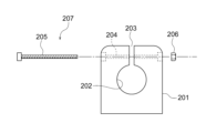
- FIG. 2 is a front view showing a seal structure of a ball joint with a dust cover as a cross section as a first embodiment; Top view of the knuckle.
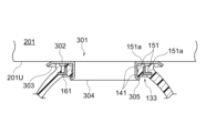
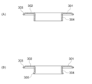
- FIG. 4 is a longitudinal front view showing a knuckle, a ferrule ring, and a small-diameter opening of a dust lip; (A) is a longitudinal front view showing the ferrule ring before incorporation, and (B) is a longitudinal front view showing the ferrule ring after incorporation.
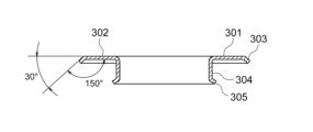
- 4 is a longitudinal front view of the ferrule ring after being assembled, showing the inclination angle of the inclined portion; 4A to 4D are longitudinal front views showing, as an example of a method of attaching the ferrule ring to the dust cover, steps of attaching the ferrule ring of the present embodiment to the dust cover over time; 4A to 4D are vertical cross-sectional front views sequentially showing the process of attaching the ferrule ring of Comparative Example 1 to the dust cover as an example of the method of attaching the ferrule ring to the dust cover.
- FIG. 1 A) to (D) are longitudinal front views showing, as an example of a method of attaching the ferrule ring to the dust cover, steps of attaching the ferrule ring of Comparative Example 2 to the dust cover over time.
- (A) to (D) are longitudinal front views showing the process of attaching the ferrule ring of Comparative Example 3 to the dust cover over time as an example of the method of attaching the ferrule ring to the dust cover.
- the longitudinal front view which shows the small diameter opening part of a dust cover as 2nd Embodiment.
- the front view which makes a dust cover a cross section and shows the sealing structure of a ball joint.
- This embodiment is an example of a ball joint 101 that connects a lower arm (not shown), which is a joint target, and a knuckle 201 .
- the seal structure of ball joint 101 of the present embodiment defines a structure for sealing between knuckle 201 and small-diameter opening 133 of dust cover 131, which will be described later.
- FIG. 1 A first embodiment will be described with reference to FIGS. 1 to 5.
- FIG. 1 A first embodiment will be described with reference to FIGS. 1 to 5.
- the ball joint 101 holds the ball head 112 provided on the ball stud 111 in the socket 121 so as to be swingable and rotatable, and the dust cover 131 seals the holding area. It has a basic structure of In FIG. 1, an arrow A indicates the swinging direction of the ball joint 101 with respect to the axis AX, and an arrow B indicates the rotating direction.
- the ball stud 111 is a metal member with a rod-shaped stud 113 extending from a spherical head 112 . Stud 113 extends from ball head 112 so that axis AX passes through the center point of ball head 112 .
- Ball joint 101 connects stud 113 to knuckle 201 .
- the knuckle 201 is a thick flat metal member.
- the knuckle 201 has a mounting hole 202 through which the stud 113 passes, and a cut connecting the mounting hole 202 to the external space over the entire length in the axial direction (coinciding with the direction of the axis AX of the ball joint 101).
- a notch 203 is provided.
- Bolt holes 204 are provided on both sides of the knuckle 201 with the notch 203 therebetween, and a nut 206 is screwed to the tip of a bolt 205 passing through the bolt hole 204 .
- a bolt 205 and a nut 206 constitute a fastener 207, and by tightening the bolt 205, the interval between the notches 203, that is, the inner diameter of the mounting hole 202 can be reduced.
- the stud 113 can be fixed to the knuckle 201 by tightening the bolt 205 there.
- the stud 113 has a large diameter portion 113a, a seal portion 113b, and a mounting portion 113c in order from the ball head 112 side toward the tip.
- the large diameter portion 113a is the portion of the stud 113 that has the largest diameter.
- the seal portion 113b is a portion that is brought into contact with a seal lip 141 provided in a small-diameter opening 133 (described later) of the dust cover 131 and causes the seal lip 141 to perform a sealing function.
- the seal portion 113b has a uniform diameter over its entire length.
- the mounting part 113c is a part that is inserted into the mounting hole 202 of the knuckle 201 and is fixed in the mounting hole 202 by tightening the fastener 207 .
- the outer diameter of the mounting portion 113c is uniform over its entire length.
- a step is provided between the mounting portion 113c and the sealing portion 113b, and the mounting portion 113c is formed to have a smaller diameter than the sealing portion 113b.
- the socket 121 accommodates a resin bearing 123 in a cylindrical housing 122 that is open at both ends, and has a bottom plate 124 that closes the bottom.
- One open end of the housing 122 is an opening 125 through which the stud 113 of the ball stud 111 is exposed to the outside.
- the bearing 123 is tightly housed in the housing 122 and fixedly held, and holds the spherical head portion 112 of the ball stud 111 so as to be swingable and rotatable.
- a contact area between the bearing 123 and the ball head 112 is filled with lubricating grease (not shown).
- the housing 122 has a mounting portion 126 formed on the outer peripheral surface on the side closer to the opening portion 125 .
- the attachment portion 126 is a small-diameter stepped opening for attaching the dust cover 131 .
- the dust cover 131 is a film-like member made of a rubber-like elastic member.
- the dust cover 131 has a small-diameter opening 133 at one end of a cup-shaped film portion 132 and a large-diameter opening 134 at the other end. Since it is a rubber-like elastic member, the dust cover 131 has flexibility and elastic restoring force.
- the large-diameter opening 134 has a clamper 135 that is fitted and attached to a mounting portion 126 provided on the outer peripheral surface of the housing 122 .
- the clamper 135 is a metallic annular member embedded in the large-diameter opening 134 made of rubber.
- the small diameter opening 133 has a seal lip 141 and a dust lip 151 .
- These lips 141 and 151 are integrally formed on the dust cover 131 to form an annular shape.
- the seal lip 141 and the dust lip 151 are arranged on the inner peripheral portion of the small-diameter opening 133 and the open end portion of the small-diameter opening 133, respectively.
- the seal lip 141 elastically covers the seal portion 113b of the stud 113 through the cylindrical portion 304 of the ferrule ring 301, which will be described later, and the space S for accommodating the spherical head portion 112 defined by the film portion 132 of the dust cover 131. hermetically seal.
- the dust lip 151 has two lip ends 151 a that are annularly projected from the open end of the small-diameter opening 133 facing the knuckle 201 .
- a ferrule ring 301 which will be described later, is interposed between the knuckle 201 and the small-diameter opening 133 .
- the lip end 151a of the dust lip 151 elastically deforms and contacts the lower surface of the knuckle 201 via the ferrule ring 301, thereby preventing foreign matter from entering the space S in the dust cover 131 from the outside.
- a reinforcing ring 161 is embedded in the small-diameter opening 133 of the dust cover 131 .
- the reinforcing ring 161 is an annular metal member and has an L-shaped cross section.
- One L-shaped piece extends in the axial direction of the dust cover 131 , that is, along the axis AX of the ball stud 111 , and another L-shaped piece extends in a direction perpendicular to the axis of the dust cover 131 .
- the ferrule ring 301 is mainly composed of an annular portion 302 that is in surface contact with the lower surface 201U of the knuckle 201 on the dust cover 131 side. , an inclined portion 303 on the outer peripheral edge, and a cylindrical portion 304 on the inner peripheral edge.
- the ferrule ring 301 is an integrally molded product in which the annular portion 302, the inclined portion 303 and the cylindrical portion 304 are formed by press working.
- the annular portion 302 is a flat plate-like annular body that contacts the lower surface 201U of the knuckle 201 . Due to the mutual contact, entry of foreign matter from the outside into between the knuckle 201 and the ferrule ring 301 is suppressed.
- the inclined portion 303 provided at the outer peripheral end of the ferrule ring 301 is inclined toward the dust cover 131 at an obtuse angle with respect to the annular portion 302 forming the inner peripheral surface of the ferrule ring 301 . sloping towards.
- the inclined portion 303 is formed by bending the outer peripheral end of the ferrule ring 301 by, for example, 30 degrees with respect to a virtual plane including the annular portion 302 . As a result, the inclined portion 303 is inclined toward the dust cover 131 at an angle of 150 degrees with the annular portion 302 . At this time, the inclined portion 303 is set at an angle of 30 degrees with respect to the lower surface 201U of the knuckle 201 when the ferrule ring 301 is assembled (see FIG. 3).
- the inclination angle of the inclined portion 303 of 150 degrees is only an example.
- the sloped portion 303 may be sloped at other angles.
- the inclined portion 303 can be obtained by bending the outer peripheral end of the ferrule ring 301 at an angle not exceeding 90 degrees.
- the dust lip 151 provided in the small-diameter opening 133 of the dust cover 131 has a smaller diameter than the inclined outer peripheral end (inclined portion 303) of the ferrule ring 301. More specifically, the outer diameter of the lip end 151 a on the outer peripheral side of the dust lip 151 is smaller than the circumference forming the boundary between the annular portion 302 and the inclined portion 303 . As a result, the dust lip 151 contacts the ferrule ring 301 on the inner peripheral side of the inclined portion 303 .
- the dust lip 151 contacts the ferrule ring 301 on the inner peripheral side of the inclined portion 303 as follows.
- Aspect 1 When the stud 113 of the ball joint 101 is not inclined, the dust lip 151 contacts the ferrule ring 301 on the inner peripheral side of the inclined portion 303.
- Aspect 2 Even when the stud 113 of the ball joint 101 is inclined, the dust lip 151 contacts the ferrule ring 301 on the inner peripheral side of the inclined portion 303.
- Two aspects can occur. In practice, either mode 1 or mode 2 may be used. However, the effect of reducing sliding torque, which will be described later, is higher in mode 2.
- the tubular portion 304 is fitted with the sealing portion 113b of the stud 113 forming part of the ball stud 111. As shown in FIG. The inner diameter of the tubular portion 304 has the same dimension as the outer diameter of the seal portion 113b.
- the cylindrical portion 304 of the ferrule ring 301 before assembly is formed in a straight tube shape that fits the seal portion 113b of the stud 113.
- the cylindrical portion 304 after assembly has an enlarged diameter at the end. This portion is a caulking portion.
- the ferrule ring 301 is manufactured singly, and the manufactured ferrule ring 301 is attached to the small-diameter opening 133 of the dust cover 131 . More specifically, the following steps are performed.
- the outer peripheral end of the ferrule ring 301 is bent at, for example, 30 degrees to form an inclined portion 303 .
- the inner peripheral end of the ferrule ring 301 is bent at right angles to form a tubular portion 304 .
- Either the inclined portion 303 or the tubular portion 304 may be formed first, or they may be formed at the same time.
- the tubular portion 304 is fitted into the opening of the small-diameter opening 133 and the ferrule ring 301 is attached to the dust cover 131 . Then, the seal lip 141 provided in the small-diameter opening 133 contacts the outer peripheral surface of the cylindrical portion 304 , and the dust lip 151 hits the annular portion 302 of the ferrule ring 301 .
- FIG. 6(C) shows a state in which the dust lip 151 provided in the small-diameter opening 133 abuts against the annular portion 302 of the ferrule ring 301 .
- a jig 401 of a crimping machine (not shown) is pressed against the opening of the cylindrical portion 304 to apply a pressing force.
- the jig 401 is a columnar or cylindrical pressing body having an outer diameter slightly larger than the inner diameter of the cylindrical portion 304, and is capable of entering the inner peripheral side of the cylindrical portion 304.
- the outer peripheral edge of the tip is formed into a curved shape.
- FIG. 6(D) when the jig 401 is pressed against the tubular portion 304 of the ferrule ring 301 to apply a pressing force, the end portion of the tubular portion 304 is pushed by the jig 401 and deformed. As a result, the small-diameter opening 133 of the dust cover 131 is crimped onto the cylindrical portion 304 of the ferrule ring 301 (see FIG. 3).
- reference numeral 305 denotes the crimped portion.
- the crimped portion 305 of the cylindrical portion 304 has an enlarged diameter and matches the large diameter portion 113a provided on the stud 113 in size and shape.
- the ferrule ring 301 is fitted with the large-diameter portion 113 a and the seal portion 113 b of the stud 113 .
- the ferrule ring 301C1 of Comparative Example 1 has similarity to the configuration example described in Patent Document 1, especially considering that the inclined portion 303 is not provided.
- a ferrule ring 301C2 of Comparative Example 2 is an example in which the outer peripheral end of the ferrule ring 301C2 is bent at right angles to form a bent portion 321 instead of the inclined portion 303 (see FIG. 8D).
- the ferrule ring 301C2 has a bent portion 321 at its outer peripheral end, which is the inclined portion 303 in this embodiment, and the dust lip 151 of the dust cover 131 is brought into contact with the inner peripheral surface of the bent portion 321 .
- a ferrule ring 301C3 of Comparative Example 3 is an example in which the outer peripheral end of the ferrule ring 301C3 is folded to form a folded portion 331 instead of the inclined portion 303 (see FIG. 9D).
- the folded portion 331 is formed by folding the outer peripheral end of the ferrule ring 301C3 at an angle exceeding 90 degrees.
- the ferrule ring 301C3 has a folded portion 331 at its outer peripheral end, which is the inclined portion 303 in this embodiment, and holds down the dust lip 151 of the dust cover 131 with the folded portion 331 .
- the small-diameter opening 133 of the dust cover 131 is held by being wrapped in the ferrule ring 301C3.
- the ferrule ring 301C3 of Comparative Example 3 differs from the ferrule ring 301 of the present embodiment, the ferrule ring 301C1 of Comparative Example 1, and the ferrule ring 301C2 of Comparative Example 2 in the mounting method to the dust cover 131.
- the folded portion 331 is not formed at the manufacturing stage of the ferrule ring 301C3 (see FIG. 9A), and is formed after the tubular portion 304 of the ferrule ring 301C3 is fitted into the opening portion of the small-diameter opening 133 (see FIG. 9B). ) (C)), and is produced before or after the caulking process using the jig 401 .
- the three comparative examples 1 to 3 have been explained above.
- these comparative examples 1 to 3 when the inclined portion 303 is changed to a straight portion 311 (comparative example 1), a bent portion 321 (comparative example 2), and a folded portion 331 (comparative example 3), , and how it differs from the ferrule ring 301 in terms of the method of attachment to the dust cover 131 .
- the straight portion 311 has a structure described in Patent Document 1
- the bent portion 321 has a structure described in Patent Document 2
- the folded portion 331 has a structure described in Patent Document 3.
- Comparative Examples 1-3 are not prior art. It is merely a comparative example to be compared with ferrule ring 301 of the present embodiment.
- the pinch bolt type knuckle 201 employed in this embodiment allows foreign matter to enter the notch 203 .
- ferrule ring 301 blocks external foreign matter that has entered through notch 203, making it difficult for stud 113 and knuckle 201 to rust.
- the ferrule ring 301 also has the effect of facilitating the installation of the dust lip 151 in the small-diameter opening 133 of the dust cover 131 .
- the dust lip 151 contacts the lower surface 201U of the knuckle 201 via the annular portion 302 of the ferrule ring 301 to prevent external foreign matter such as water and dust from entering the joint.
- an angular change occurs between the knuckle 201 and a lower arm (not shown), which is a joint object.
- the spherical head 112 swings (arrow A in FIG. 1) or rotates (arrow B) within the socket 121 so that the ball stud 111 can swing or rotate accordingly.
- Angular changes between two joint objects are absorbed by such movements of the ball head 112 .
- the dust cover 131 is deformed when the ball stud 111 swings. Since the dust cover 131 is a rubber-like elastic member, it has flexibility and elastic restoring force. At (the left side in FIG. 1), the film portion 132 is bent and contracted. The dust cover 131 absorbs deformation due to swinging of the ball stud 111 .
- the outer peripheral end of the ferrule ring 301C1 of Comparative Example 1 is a straight portion 311 that continues in the same plane as the annular portion 302 (see FIG. 7(D)). For this reason, when the mouth opening phenomenon occurs, the entry of foreign matter from the outside through the gap generated between the small-diameter opening 133 is allowed.
- the inclined portion 303 covers the gap between the ferrule ring 301 and the small-diameter opening 133 when the opening phenomenon occurs. Therefore, according to the present embodiment, even if the opening phenomenon occurs, the sloped portion 303 suppresses the entry of external foreign matter through the gap formed between the knuckle 201 and the small-diameter opening portion 133, thereby improving the sealing function. can be maintained.
- the ferrule ring 301C2 of Comparative Example 2 is provided with a bent portion 321 by bending the outer peripheral edge at a right angle. It is in contact with the surface (see FIG. 8(D)).
- the stud 113 swings and rotates, sliding occurs between the bent outer peripheral edge and the small-diameter opening 133 of the dust cover 131 . The repeated sliding accelerates wear of the small-diameter opening 133 .
- the outer peripheral edge of the ferrule ring 301 is not bent at a right angle, but the inclined portion 303 is inclined toward the dust cover 131 side at an obtuse angle with respect to the annular portion 302 on the inner peripheral side. , to reduce the sliding torque with the dust lip 151 provided in the small-diameter opening 133 .
- the diameter of the lip end 151a on the outer peripheral side of the dust lip 151 is made smaller than that of the inclined portion 303 so that the dust lip 151 contacts the ferrule ring 301 on the inner peripheral side of the inclined portion 303, the dust lip 151 and the inclined portion 303 (in the case of mode 2 above), or even if it occurs, it can be reduced (in the case of mode 1 above). Therefore, it is possible to suppress wear of the small-diameter opening 133 and improve its durability.
- the ferrule ring 301C3 of Comparative Example 3 presses down the small-diameter opening 133 of the dust cover 131 with the folded portion 331 and holds the small-diameter opening 133 so as to wrap it. Therefore, it is possible to suppress the opening phenomenon of the small-diameter opening 133 .
- the folded portion 331 cannot be formed in advance on the ferrule ring 301C3.
- the folded portion 331 needs to be formed before or after forming the caulked portion 305 by the jig 401 after the cylindrical portion 304 of the ferrule ring 301C3 is fitted into the opening portion of the small-diameter opening portion 133 . Therefore, when the ferrule ring 301C3 is manufactured, the folded portion 331 cannot be press-worked at the same time, and the number of manufacturing steps inevitably increases.
- the ferrule ring 301C1 of Comparative Example 1 has been described as having the straight portion 311 at the outer peripheral end, but the straight portion 311 is not formed by special processing and is merely the outer peripheral end of the annular portion 302 .
- the outer peripheral end naturally becomes the straight portion 311 .
- the inclined portion 303 provided in the ferrule ring 301 of the present embodiment can be formed by one press working if the ferrule ring 301 including the cylindrical portion 304 is integrally formed by press working. It is possible. Therefore, the number of manufacturing steps is the same as in Comparative Example 1, even though the inclined portion 303, which does not exist in Comparative Example 1, is provided.
- the ferrule ring 301 can be completed before combining with the dust cover 131 .
- processing after combining with the dust cover 131 is unnecessary. Therefore, there is no need to process the ferrule ring 301 after it is combined with the dust cover 131, and workability can be improved.
- FIG. 10 A second embodiment will be described with reference to FIGS. 10 and 11.
- FIG. 10 The same parts as in the first embodiment are denoted by the same reference numerals, and the description thereof is omitted.
- this embodiment is an example in which the dust lip 151 is not provided in the small-diameter opening 133 of the dust cover 131, and the metal reinforcing ring 161 is exposed.
- the rubber-like elastic material forming the small-diameter opening 133 is provided so as to cover the inner peripheral side and the outer peripheral side of the reinforcing ring 161 .
- the inclined portion 303 of the ferrule ring 301 is provided at a position so as to cover the small diameter opening 133 of the dust cover 131 from the outer peripheral side and not to interfere with the small diameter opening 133 .
- the angle at which the inclined portion 303 is bent does not necessarily have to be 30 degrees.
- the angle at which the inclined portion 303 is bent is 5 degrees or more, in other words, the angle formed with the inner peripheral surface of the ferrule ring 301 is 175 degrees or less because the stud 113 of the ball joint 101 swings.
- the inclined portion 303 does not necessarily have to be formed by bending the outer peripheral end of the ferrule ring 301 . Another member forming the inclined portion 303 may be joined to the outer peripheral edge of the ferrule ring 301 . Also at this time, it is desirable that the inclined portion 303 is inclined at an obtuse angle of 175 degrees or less with respect to the inner peripheral surface of the ferrule ring 301 .
- the clamper 135 may be configured to clamp the large-diameter opening 134 from its outer peripheral side.
- the clamper 135 may not necessarily be provided.
- the reinforcing ring 161 may be made of a material other than metal, such as resin.
- a shape other than the L shape, for example, a rectangular shape in cross section may be used.
- the reinforcing ring 161 is not necessarily an essential element, and the small-diameter opening 133 may be formed without embedding the reinforcing ring 161 .
Landscapes
- Engineering & Computer Science (AREA)
- General Engineering & Computer Science (AREA)
- Mechanical Engineering (AREA)
- Pivots And Pivotal Connections (AREA)
- Sealing Devices (AREA)
Abstract
Structure d'étanchéité de joint à rotule présentant une bague de virole interposée entre l'ouverture de petit diamètre d'un couvercle anti-poussière et un joint d'articulation. Le joint à rotule relie le joint d'articulation à un goujon, et une tête sphérique sur l'extrémité du goujon est logée dans une douille de façon à pouvoir osciller et tourner. Un couvercle anti-poussière présente une ouverture de grand diamètre entourant la douille qui loge la tête sphérique, et l'ouverture de petit diamètre entourant le goujon, l'ouverture de grand diamètre et l'ouverture de petit diamètre étant reliées par une membrane. L'anneau de virole est pourvu d'une partie annulaire qui supprime l'entrée de poussière à travers une encoche qui se produit lorsque, par exemple, un joint d'articulation de boulon de pincement est utilisé, et présente, au niveau de l'extrémité périphérique externe, une partie inclinée qui est inclinée vers le côté couvercle anti-poussière.
Applications Claiming Priority (2)
| Application Number | Priority Date | Filing Date | Title |
|---|---|---|---|
| JP2022026306 | 2022-02-24 | ||
| JP2022-026306 | 2022-02-24 |
Publications (1)
| Publication Number | Publication Date |
|---|---|
| WO2023162678A1 true WO2023162678A1 (fr) | 2023-08-31 |
Family
ID=87765638
Family Applications (1)
| Application Number | Title | Priority Date | Filing Date |
|---|---|---|---|
| PCT/JP2023/004021 WO2023162678A1 (fr) | 2022-02-24 | 2023-02-07 | Structure d'étanchéité de joint à rotule et procédé de montage de bague de virole |
Country Status (1)
| Country | Link |
|---|---|
| WO (1) | WO2023162678A1 (fr) |
Citations (5)
| Publication number | Priority date | Publication date | Assignee | Title |
|---|---|---|---|---|
| US6357956B1 (en) * | 1999-12-10 | 2002-03-19 | Dana Corporation | Unitized boot seal for ball joints |
| JP2011064208A (ja) | 2009-09-15 | 2011-03-31 | Nok Corp | ボールジョイント用ダストカバー |
| JP2015152058A (ja) * | 2014-02-13 | 2015-08-24 | Nok株式会社 | ボールジョイント用ダストカバー |
| JP2016125625A (ja) | 2015-01-07 | 2016-07-11 | Nok株式会社 | ダストカバー |
| WO2017018169A1 (fr) | 2015-07-27 | 2017-02-02 | Nok株式会社 | Capuchon anti-poussière pour joint à rotule |
-
2023
- 2023-02-07 WO PCT/JP2023/004021 patent/WO2023162678A1/fr unknown
Patent Citations (5)
| Publication number | Priority date | Publication date | Assignee | Title |
|---|---|---|---|---|
| US6357956B1 (en) * | 1999-12-10 | 2002-03-19 | Dana Corporation | Unitized boot seal for ball joints |
| JP2011064208A (ja) | 2009-09-15 | 2011-03-31 | Nok Corp | ボールジョイント用ダストカバー |
| JP2015152058A (ja) * | 2014-02-13 | 2015-08-24 | Nok株式会社 | ボールジョイント用ダストカバー |
| JP2016125625A (ja) | 2015-01-07 | 2016-07-11 | Nok株式会社 | ダストカバー |
| WO2017018169A1 (fr) | 2015-07-27 | 2017-02-02 | Nok株式会社 | Capuchon anti-poussière pour joint à rotule |
Similar Documents
| Publication | Publication Date | Title |
|---|---|---|
| US20060188324A1 (en) | Joint structure of ball joint and arm | |
| US20030069075A1 (en) | Constant velocity joint boot | |
| US7090425B2 (en) | Balljoint | |
| JP6043093B2 (ja) | ボールジョイント | |
| US10626915B2 (en) | Vertical control arm bushing with dust boot having strengthening portions | |
| WO2023162678A1 (fr) | Structure d'étanchéité de joint à rotule et procédé de montage de bague de virole | |
| WO2003056194A1 (fr) | Joint spherique | |
| US10527087B2 (en) | Socket assembly and method of making | |
| EP3196488B1 (fr) | Joint à rotule | |
| JP3412480B2 (ja) | ボールジョイント | |
| JP3824293B2 (ja) | ボールジョイント | |
| JP4498124B2 (ja) | ボールジョイント | |
| US11085486B2 (en) | Seal member of ball joint | |
| WO2014097767A1 (fr) | Couvercle anti-poussières de joint à rotule | |
| JP2004293572A (ja) | ボールジョイント及びその製造方法 | |
| KR101398982B1 (ko) | 휠 베어링 체결 구조 및 휠 베어링 체결 방법 | |
| JPH09250642A (ja) | 密封装置 | |
| JP4069269B2 (ja) | ボールジョイント | |
| JP2020094648A (ja) | ブーツの取付構造 | |
| JP2002310209A (ja) | ストラットマウント | |
| JPH0236973Y2 (fr) | ||
| JPS621500Y2 (fr) | ||
| JP2002031125A (ja) | ボールジョイント | |
| JPH0523854Y2 (fr) | ||
| JP2731996B2 (ja) | ボールジョイント及びその製造方法 |
Legal Events
| Date | Code | Title | Description |
|---|---|---|---|
| 121 | Ep: the epo has been informed by wipo that ep was designated in this application |
Ref document number: 23759682 Country of ref document: EP Kind code of ref document: A1 |