WO2023162398A1 - レーザ加工ヘッドおよびレーザ加工機 - Google Patents
レーザ加工ヘッドおよびレーザ加工機 Download PDFInfo
- Publication number
- WO2023162398A1 WO2023162398A1 PCT/JP2022/044975 JP2022044975W WO2023162398A1 WO 2023162398 A1 WO2023162398 A1 WO 2023162398A1 JP 2022044975 W JP2022044975 W JP 2022044975W WO 2023162398 A1 WO2023162398 A1 WO 2023162398A1
- Authority
- WO
- WIPO (PCT)
- Prior art keywords
- inclined surface
- processing head
- laser processing
- magnet
- pin
- Prior art date
- Legal status (The legal status is an assumption and is not a legal conclusion. Google has not performed a legal analysis and makes no representation as to the accuracy of the status listed.)
- Ceased
Links
Images






















Classifications
-
- B—PERFORMING OPERATIONS; TRANSPORTING
- B23—MACHINE TOOLS; METAL-WORKING NOT OTHERWISE PROVIDED FOR
- B23K—SOLDERING OR UNSOLDERING; WELDING; CLADDING OR PLATING BY SOLDERING OR WELDING; CUTTING BY APPLYING HEAT LOCALLY, e.g. FLAME CUTTING; WORKING BY LASER BEAM
- B23K26/00—Working by laser beam, e.g. welding, cutting or boring
- B23K26/20—Bonding
- B23K26/21—Bonding by welding
-
- B—PERFORMING OPERATIONS; TRANSPORTING
- B23—MACHINE TOOLS; METAL-WORKING NOT OTHERWISE PROVIDED FOR
- B23K—SOLDERING OR UNSOLDERING; WELDING; CLADDING OR PLATING BY SOLDERING OR WELDING; CUTTING BY APPLYING HEAT LOCALLY, e.g. FLAME CUTTING; WORKING BY LASER BEAM
- B23K26/00—Working by laser beam, e.g. welding, cutting or boring
- B23K26/14—Working by laser beam, e.g. welding, cutting or boring using a fluid stream, e.g. a jet of gas, in conjunction with the laser beam; Nozzles therefor
- B23K26/1462—Nozzles; Features related to nozzles
- B23K26/1482—Detachable nozzles, e.g. exchangeable or provided with breakaway lines
-
- B—PERFORMING OPERATIONS; TRANSPORTING
- B23—MACHINE TOOLS; METAL-WORKING NOT OTHERWISE PROVIDED FOR
- B23K—SOLDERING OR UNSOLDERING; WELDING; CLADDING OR PLATING BY SOLDERING OR WELDING; CUTTING BY APPLYING HEAT LOCALLY, e.g. FLAME CUTTING; WORKING BY LASER BEAM
- B23K26/00—Working by laser beam, e.g. welding, cutting or boring
- B23K26/34—Laser welding for purposes other than joining
-
- B—PERFORMING OPERATIONS; TRANSPORTING
- B23—MACHINE TOOLS; METAL-WORKING NOT OTHERWISE PROVIDED FOR
- B23K—SOLDERING OR UNSOLDERING; WELDING; CLADDING OR PLATING BY SOLDERING OR WELDING; CUTTING BY APPLYING HEAT LOCALLY, e.g. FLAME CUTTING; WORKING BY LASER BEAM
- B23K26/00—Working by laser beam, e.g. welding, cutting or boring
- B23K26/70—Auxiliary operations or equipment
Definitions
- a laser processing head having an optical path hole formed therein for passing a laser beam and extending in a first direction. , a first machining head, and a second machining head arranged side by side with the first machining head in a first direction and detachably connected to the first machining head. ing.
- a first inclined surface that is inclined with respect to the first direction is formed at an end portion of the first machining head facing the second machining head.
- a second slanted surface parallel to the first slanted surface is formed at the end of the second machining head facing the first machining head.
- the rotating shaft 25 rotates the stage 30 .
- the additional manufacturing apparatus 100 can make the posture of the work suitable for processing.
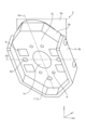
- FIG. 15 is a perspective view showing the first processing head section 2.
- FIG. FIG. 16 is a perspective view showing the second processing head section 3.
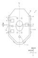
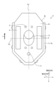
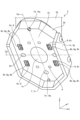
- the first inclined surface 2c shown in FIG. 15 and the second inclined surface 3c shown in FIG. 16 have the same external shape and the same outer peripheral dimensions.
- the laser processing head 1 includes a cover 1c surrounding the first inclined surface 2c and the second inclined surface 3c. Rubber, for example, is used as the material of the cover 1c.
- the cover 1c has a first cover 2g attached to the first plate portion 2b shown in FIG. 15 and a second cover 3g attached to the second plate portion 3b shown in FIG. ing.
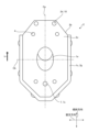
- the arrangement of the movable pins 4 may be as shown in FIG. 36 is a perspective view showing an end portion of the first processing head portion 2 of the laser processing head 1 according to the ninth modification of the first embodiment, which faces the second processing head portion 3.
- FIG. The number of movable pins 4 shown in FIG. 36 is two.
- the two movable pins 4 are provided above the portion of the first inclined surface 2c where the optical path hole 1a is opened in the direction of inclination.
- the movable pins 4 are arranged one by one at positions offset from the first center line Ca on one side and the other in the orthogonal direction with the first center line Ca interposed therebetween.
- the movable pins 4 may be arranged as shown in FIGS. 38 and 39.
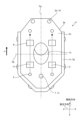
- 38 is a perspective view showing an end portion of the first processing head portion 2 of the laser processing head 1 according to the eleventh modification of the first embodiment, which faces the second processing head portion 3.
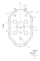
- FIG. 39 is a perspective view showing an end portion of the second processing head portion 3 of the laser processing head 1 according to the eleventh modification of the first embodiment, which faces the first processing head portion 2.
- FIG. 38 and 39 in this modification, the movable pin 4 is provided on the second plate portion 3b, and the magnet 6 is provided on the first plate portion 2b. That is, the movable pin 4 and the magnet 6 are provided on different plate portions.
- One magnet 6 that is arranged in the lowermost position in the direction of inclination is arranged on the first center line Ca.
- the remaining two magnets 6 are arranged at positions offset from the first center line Ca in one and the other orthogonal directions across the first center line Ca.
- the remaining two magnets 6 are arranged symmetrically with respect to the first center line Ca.
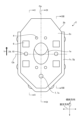
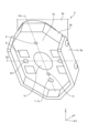
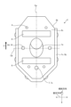
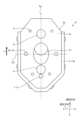
- the magnets 6 may be arranged as shown in FIG. 53 is a plan view showing an end portion of the first processing head portion 2 of the laser processing head 1 according to Modification Example 23 of Embodiment 1, which faces the second processing head portion 3.
- FIG. 53 The number of magnets 6 shown in FIG. 53 is two.
- the shape of the magnet 6 is circular.
- the two magnets 6 are arranged one each above and below the portion of the first inclined surface 2c where the optical path hole 1a is opened.
- the two magnets 6 are arranged on the same straight line along the direction of inclination.
- the two magnets 6 are arranged on the first centerline Ca.
- the sealing member 3h is arranged at a position closer to the optical path hole 1a than the movable pin 4, the magnet 6, the contact sensor 7, the sensor contact pin 9, and the like.
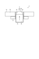
- the second inclined surface 3c is provided with the sealing member 3h which is arranged so as to surround the opening of the optical path hole 1a and seals between the first inclined surface 2c and the second inclined surface 3c.
- the gas can be prevented from leaking out of the laser processing head 1 from between the first inclined surface 2c and the second inclined surface 3c.
- the seal member 3h may be provided on at least one of the first inclined surface 2c and the second inclined surface 3c.
- the opening of the optical path hole 1a may be surrounded by a plurality of sealing members 3h having different diameters.
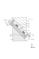
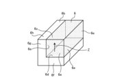
- FIG. 62 is a perspective view showing the magnet 6 and the yoke 6b of the laser processing head 1 according to Modification 30 of Embodiment 1.
- FIG. This modification differs from modification 29 in the shape of the yoke 6b.
- the protruding corner 6k of the yoke 6b may be chamfered into an R shape.
- the external corner portion 6k has a curved shape.
Landscapes
- Engineering & Computer Science (AREA)
- Physics & Mathematics (AREA)
- Optics & Photonics (AREA)
- Plasma & Fusion (AREA)
- Mechanical Engineering (AREA)
- Laser Beam Processing (AREA)
Priority Applications (2)
| Application Number | Priority Date | Filing Date | Title |
|---|---|---|---|
| JP2024502842A JP7558448B2 (ja) | 2022-02-22 | 2022-12-06 | レーザ加工ヘッドおよびレーザ加工機 |
| US18/836,447 US20250108456A1 (en) | 2022-02-22 | 2022-12-06 | Laser processing head and laser processing machine |
Applications Claiming Priority (2)
| Application Number | Priority Date | Filing Date | Title |
|---|---|---|---|
| JP2022025926 | 2022-02-22 | ||
| JP2022-025926 | 2022-02-22 |
Publications (1)
| Publication Number | Publication Date |
|---|---|
| WO2023162398A1 true WO2023162398A1 (ja) | 2023-08-31 |
Family
ID=87765532
Family Applications (1)
| Application Number | Title | Priority Date | Filing Date |
|---|---|---|---|
| PCT/JP2022/044975 Ceased WO2023162398A1 (ja) | 2022-02-22 | 2022-12-06 | レーザ加工ヘッドおよびレーザ加工機 |
Country Status (3)
| Country | Link |
|---|---|
| US (1) | US20250108456A1 (https=) |
| JP (1) | JP7558448B2 (https=) |
| WO (1) | WO2023162398A1 (https=) |
Citations (3)
| Publication number | Priority date | Publication date | Assignee | Title |
|---|---|---|---|---|
| JPS60166483U (ja) * | 1984-04-06 | 1985-11-05 | 児玉化学工業株式会社 | レ−ザロボツトのノズル |
| JPH04104271U (ja) * | 1991-02-07 | 1992-09-08 | 株式会社小松製作所 | 熱切断機用ト−チの破損防止装置 |
| WO2021075266A1 (ja) * | 2019-10-16 | 2021-04-22 | 三菱電機株式会社 | 加工ヘッドおよびレーザ加工装置 |
-
2022
- 2022-12-06 WO PCT/JP2022/044975 patent/WO2023162398A1/ja not_active Ceased
- 2022-12-06 JP JP2024502842A patent/JP7558448B2/ja active Active
- 2022-12-06 US US18/836,447 patent/US20250108456A1/en active Pending
Patent Citations (3)
| Publication number | Priority date | Publication date | Assignee | Title |
|---|---|---|---|---|
| JPS60166483U (ja) * | 1984-04-06 | 1985-11-05 | 児玉化学工業株式会社 | レ−ザロボツトのノズル |
| JPH04104271U (ja) * | 1991-02-07 | 1992-09-08 | 株式会社小松製作所 | 熱切断機用ト−チの破損防止装置 |
| WO2021075266A1 (ja) * | 2019-10-16 | 2021-04-22 | 三菱電機株式会社 | 加工ヘッドおよびレーザ加工装置 |
Also Published As
| Publication number | Publication date |
|---|---|
| JP7558448B2 (ja) | 2024-09-30 |
| US20250108456A1 (en) | 2025-04-03 |
| JPWO2023162398A1 (https=) | 2023-08-31 |
Similar Documents
| Publication | Publication Date | Title |
|---|---|---|
| CN102362323B (zh) | 电子元件的绕线方法及绕线装置 | |
| KR20100098638A (ko) | 다축 리니어 모터 및 부품 이송 장치 | |
| JPWO2018055708A1 (ja) | リニアコンベア装置 | |
| TWI708296B (zh) | 打線接合裝置 | |
| KR20140090091A (ko) | 와이어 진동기를 포함하는 용접 장치 | |
| JP2010105140A (ja) | 自動組立装置 | |
| US6706991B2 (en) | Welding method and welding system for projection bolt | |
| KR20100098605A (ko) | 리니어 모터 및 부품 이송 장치 | |
| WO2023162398A1 (ja) | レーザ加工ヘッドおよびレーザ加工機 | |
| WO2023162397A1 (ja) | レーザ加工ヘッドおよびレーザ加工機 | |
| CN115194318B (zh) | 激光接带设备 | |
| JP3011010B2 (ja) | 部品の保持ヘッド | |
| TW202040709A (zh) | 毛細管導引裝置以及打線接合裝置 | |
| CN113508003B (zh) | 拆装装置、加工机及加工头 | |
| JP2007000985A (ja) | 治具、被加工物の製造方法及びミシンヘッドの製造方法 | |
| JP5440982B2 (ja) | 部品振り分け装置 | |
| JP2539110Y2 (ja) | 熱切断機用ト−チの破損防止装置 | |
| JP7245056B2 (ja) | 加工ヘッド装置 | |
| KR100648492B1 (ko) | 본딩 장치 | |
| JP3640093B2 (ja) | 移送装置 | |
| JPH10303241A (ja) | ワイヤボンダー | |
| JP7799566B2 (ja) | 保持治具及び被加工部材の保持方法 | |
| WO2018134912A1 (ja) | 部品挿入機 | |
| US11465367B2 (en) | Vibration welding device | |
| JP4740697B2 (ja) | 超音波振動切削装置 |
Legal Events
| Date | Code | Title | Description |
|---|---|---|---|
| 121 | Ep: the epo has been informed by wipo that ep was designated in this application |
Ref document number: 22928915 Country of ref document: EP Kind code of ref document: A1 |
|
| WWE | Wipo information: entry into national phase |
Ref document number: 2024502842 Country of ref document: JP |
|
| WWE | Wipo information: entry into national phase |
Ref document number: 18836447 Country of ref document: US |
|
| NENP | Non-entry into the national phase |
Ref country code: DE |
|
| 122 | Ep: pct application non-entry in european phase |
Ref document number: 22928915 Country of ref document: EP Kind code of ref document: A1 |
|
| WWP | Wipo information: published in national office |
Ref document number: 18836447 Country of ref document: US |