WO2023162357A1 - 回転電機のステーターおよび回転電機のステーターの製造方法 - Google Patents
回転電機のステーターおよび回転電機のステーターの製造方法 Download PDFInfo
- Publication number
- WO2023162357A1 WO2023162357A1 PCT/JP2022/041402 JP2022041402W WO2023162357A1 WO 2023162357 A1 WO2023162357 A1 WO 2023162357A1 JP 2022041402 W JP2022041402 W JP 2022041402W WO 2023162357 A1 WO2023162357 A1 WO 2023162357A1
- Authority
- WO
- WIPO (PCT)
- Prior art keywords
- insulating film
- insulator
- stator
- iron core
- electric machine
- Prior art date
- Legal status (The legal status is an assumption and is not a legal conclusion. Google has not performed a legal analysis and makes no representation as to the accuracy of the status listed.)
- Ceased
Links
Images









Classifications
-
- H—ELECTRICITY
- H02—GENERATION; CONVERSION OR DISTRIBUTION OF ELECTRIC POWER
- H02K—DYNAMO-ELECTRIC MACHINES
- H02K1/00—Details of the magnetic circuit
- H02K1/06—Details of the magnetic circuit characterised by the shape, form or construction
- H02K1/12—Stationary parts of the magnetic circuit
- H02K1/18—Means for mounting or fastening magnetic stationary parts on to, or to, the stator structures
-
- H—ELECTRICITY
- H02—GENERATION; CONVERSION OR DISTRIBUTION OF ELECTRIC POWER
- H02K—DYNAMO-ELECTRIC MACHINES
- H02K15/00—Processes or apparatus specially adapted for manufacturing, assembling, maintaining or repairing of dynamo-electric machines
- H02K15/02—Processes or apparatus specially adapted for manufacturing, assembling, maintaining or repairing of dynamo-electric machines of stator or rotor bodies
-
- H—ELECTRICITY
- H02—GENERATION; CONVERSION OR DISTRIBUTION OF ELECTRIC POWER
- H02K—DYNAMO-ELECTRIC MACHINES
- H02K15/00—Processes or apparatus specially adapted for manufacturing, assembling, maintaining or repairing of dynamo-electric machines
- H02K15/12—Impregnating, moulding insulation, heating or drying of windings, stators, rotors or machines
-
- H—ELECTRICITY
- H02—GENERATION; CONVERSION OR DISTRIBUTION OF ELECTRIC POWER
- H02K—DYNAMO-ELECTRIC MACHINES
- H02K3/00—Details of windings
- H02K3/32—Windings characterised by the shape, form or construction of the insulation
- H02K3/34—Windings characterised by the shape, form or construction of the insulation between conductors or between conductor and core, e.g. slot insulation
-
- Y—GENERAL TAGGING OF NEW TECHNOLOGICAL DEVELOPMENTS; GENERAL TAGGING OF CROSS-SECTIONAL TECHNOLOGIES SPANNING OVER SEVERAL SECTIONS OF THE IPC; TECHNICAL SUBJECTS COVERED BY FORMER USPC CROSS-REFERENCE ART COLLECTIONS [XRACs] AND DIGESTS
- Y02—TECHNOLOGIES OR APPLICATIONS FOR MITIGATION OR ADAPTATION AGAINST CLIMATE CHANGE
- Y02T—CLIMATE CHANGE MITIGATION TECHNOLOGIES RELATED TO TRANSPORTATION
- Y02T10/00—Road transport of goods or passengers
- Y02T10/60—Other road transportation technologies with climate change mitigation effect
- Y02T10/64—Electric machine technologies in electromobility
Definitions
- This application relates to a stator for a rotating electrical machine and a method for manufacturing a stator for a rotating electrical machine.
- Patent Document 1 As a component of the stator of a rotating electric machine, there is an insulator for insulating the iron core and the wound conductor. Insulators are often manufactured by injection molding, and as a conventional technology, in order to reduce the thickness of the insulating layer, there has been a technique that secures insulation by replacing a part of the resin with an insulating film (Patent Document 1).
- the present application discloses a technique for solving the above-described problems.
- the purpose is to ensure that
- a stator for a rotary electric machine disclosed in the present application has an iron core consisting of a back yoke portion and a tooth portion arranged in an annular shape, an insulator is formed on the outer periphery of the tooth portion, and a conducting wire is wound around the insulator. is a thing, An insulating film is arranged between the iron core and the conductor, and the adjacent iron core and the insulator arranged in an annular shape are connected by the insulating film. The length of the tooth portions in the iron core is greater than the circumferential length of the tooth portions in the adjacent iron cores when they are arranged in an annular shape.
- a method of manufacturing a stator for a rotary electric machine disclosed in the present application includes placing an insulating film on the surface of an iron core and molding an insulator on the insulating film.
- Another method of manufacturing a stator for a rotating electric machine disclosed in the present application comprises the steps of fixing an insulating film and an insulator continuously, and fitting a core to the insulator.
- the insulation distance is secured between the conductor wire after winding and the back yoke portion or between the adjacent teeth, and the insulation is achieved. can be ensured.
- FIG. 1 is a cross-sectional view showing a three-phase (UVW phase) AC rotary electric machine according to Embodiment 1;
- FIG. 3 is a perspective view showing three iron core portions in the stator of the rotary electric machine according to Embodiment 1;
- FIG. FIG. 2 is a side cross-sectional view showing the apparatus for manufacturing the stator core and insulator of the rotary electric machine according to Embodiment 1; It is the side view seen from the A direction in FIG.
- FIG. 2 is a side cross-sectional view showing insulator, iron core and insulating film portions according to Embodiment 1;
- FIG. 2 is a side cross-sectional view showing insulator, iron core and insulating film portions according to Embodiment 1;
- FIG. 1 is a cross-sectional view showing a three-phase (UVW phase) AC rotary electric machine according to Embodiment 1;
- FIG. 3 is a perspective view showing three iron core portions in the stator of the rotary
- FIG. 2 is a side cross-sectional view showing insulator, iron core and insulating film portions according to Embodiment 1;
- FIG. 2 is a side cross-sectional view showing insulator, iron core and insulating film portions according to Embodiment 1;
- FIG. 2 is a side cross-sectional view showing insulator, iron core and insulating film portions according to Embodiment 1;
- FIG. 3 is a side cross-sectional view showing the insulator, the iron core, and the insulation film after the winding process according to Embodiment 1;
- FIG. 4 is a side cross-sectional view showing insulator, iron core and insulating film portions in the assembly process according to Embodiment 1;
- FIG. 11 is a perspective view showing three iron core portions of a stator of a rotating electric machine according to Embodiment 2;
- FIG. 8 is a plan view showing an insulating film used in Embodiment 2;
- FIG. 8 is a side cross-sectional view showing a manufacturing apparatus for a stator iron core and an insulator for a rotary electric machine according to Embodiment 2;
- FIG. 9 is a perspective view showing nine core portions of a stator of a rotating electric machine according to Embodiment 2;
- FIG. 8 is a plan view showing an insulating film used in Embodiment 2;
- FIG. 11 is a perspective view showing three core portions of a stator of a rotating electric machine according to Embodiment 3;
- FIG. 11 is a side cross-sectional view showing an apparatus for manufacturing an insulator for a rotating electric machine according to Embodiment 3;
- FIG. 10 is a plan view showing an insulating film used in Embodiment 3;
- FIG. 11 is a perspective view showing three core portions of a stator of a rotating electric machine according to Embodiment 3;
- FIG. 11 is a side cross-sectional view showing a method of manufacturing a stator iron core and an insulator of a rotary electric machine according to Embodiment 4;
- FIG. 1 is a cross-sectional view showing a three-phase (UVW phase) AC rotary electric machine 10 according to Embodiment 1.
- the rotary electric machine 10 includes an annular stator 12 fixed by a housing 11 , a rotor 13 provided on the inner periphery of the stator 12 , and a rotating shaft 14 attached to the center of the rotor 13 .
- the stator 12 has an iron core 4, an insulator 6 made of a resin and an insulating film 5 which are insulating members, and a conductor wire 7 wound around the iron core 4 via the insulator 6.
- the stator 12 is configured by annularly arranging the stator cores 15 having
- the rotor 13 is composed of a rotor core 20 and permanent magnets 21 provided on the outer peripheral surface of the rotor core 20, and a magnetic field generated between the rotor core 20 and the stator core 15 generates rotational force.
- the rotating shaft 14 is fixed to a rotor core 20 and rotates together with the rotor 13 while being supported by bearings 22 to transmit power.
- Fig. 2 is a perspective view showing the 3-teeth portion of the stator of the rotary electric machine.
- an annular stator is divided in the circumferential direction into a plurality of iron cores and insulators.
- the insulators 6 are continuously connected via a rectangular insulating film 5 having a large longitudinal direction, and are configured in a connected state.
- An insulating film 5 is arranged between the insulator 6 and the iron core 4 .
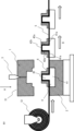
- Fig. 3 is a side cross-sectional view showing a manufacturing apparatus for a stator iron core and an insulator of a rotary electric machine
- Fig. 4 is a side view seen from the direction A in Fig. 3.
- the upper mold 1 of the molding die 31 is opened from the lower mold 2 (the movable upper mold 1 and the lower mold 2 are separated), and the insulating film 5 wound around the roll 51 is attached to the iron core. 4, and the upper mold 1 of the mold is closed.
- Molten molding resin is injected from the cylinder 3 of the injection molding machine through the resin injection port 32 (position is an example) provided in the upper mold 1 of the molding die, and the mold formed by the upper mold 1 and the lower mold 2 is injected. Fill the inside of the mold cavity.
- injection pressure is uniformly applied to both axial end surfaces of the iron core 4 . This injection pressure imparts a force to adhere to the iron core 4, the insulating film 5 and the insulator 6.
- FIG. 1 is a side cross-sectional view showing
- the insulator 6 is formed by cooling and solidifying the molding resin while the injection pressure is applied, and the iron core 4, the insulating film 5 and the insulator 6 are integrated and fixed in a compressed state.
- the upper die 1 of the molding die 31 is opened with respect to the lower die 2, and the insulator 6 and the iron core 4 integrated with the insulating film 5 are removed as shown in FIGS. 4, it is sent in the direction opposite to the roll 51 side.
- the iron core 4 and the insulating film 5 are pressure-bonded by the same method, and injection molding is performed.
- FIG. 2 the insulator 6 and the iron core 4 with the insulating film 5 interposed therebetween are molded in a continuously connected state.
- the iron core 4 is composed of a back yoke portion 41 and teeth portions 42
- the insulators 6 are formed on the outer circumferences of the teeth portions 42
- the conducting wire is wound around the insulators 6.
- Insulation between the conductor and the core 4 is ensured by the insulator 6 .
- the insulating film 5 is arranged on the side surface 42a of the tooth portion 42, the rotor-side surface 42b of the tooth portion 42, and the rotor-side surface 41a of the back yoke portion 41, and the insulator 6 is disposed on the insulating film. 5 is to be molded on.
- the resin insulator 6 is made of PBT (polybutylene terephthalate), LCP (liquid crystal polyester LIQUID CRYSTAL POLYMER), POM (polyacetal POLYACETAL), ABS (acrylonitrile-butadiene-styrene copolymer resin) ACRYLONITRILE BUTADIE.
- Thermoplastic resin such as NE STYRENE
- the insulating film 5 is a film-like insulator made of a thermoplastic resin (eg, polyethylene terephthalate, polyphenylene sulfide, polyetheretherketone, polyimide, etc.) and having a thickness of about 0.03 to 1 mm.
- the shape of the insulating film 5 varies depending on the shape of the iron core 4, and is not limited to the shape illustrated in this embodiment.
- the insulating film 5 made of thermoplastic resin undergoes plastic deformation such as bending and elongation due to the heat received during injection molding, and has the effect of adhering to the iron core 4.
- the shapes of the core 4 and the insulator 6 can be arbitrarily changed according to product specifications, and are not limited to the shapes illustrated in the present embodiment. Moreover, since the end portion 5A of the insulating film 5 is sealed inside the insulator 6, it is possible to prevent the insulating film 5 from peeling off from the iron core 4. FIG. Further, in this embodiment, since the method of melting the insulating film 5 by heat and adhering it to the insulating resin is not adopted, the material is selected so that the melting temperature of the insulating film 5 is lower than the melting temperature of the insulating resin. does not need to be selected. As a result, it is possible to select a wide range of materials for the insulating film 5 and the molding resin, so that it is possible to use not only thermoplastic resins but also thermosetting resins.
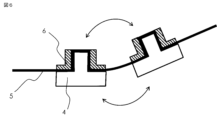
- the insulating film 5 and 6 are side cross-sectional views showing insulator 6, iron core 4 and insulating film 5 parts.
- the insulating film 5 is in the form of a rectangular thin sheet with a thickness of about 0.03 to 1 mm, so that it can be easily bent in any direction.
- FIG. 6 it can be bent to the teeth side of the core 4 (upper side in FIG. 6), and as shown in FIG. 5, it can be bent to the back yoke side of the core 4 (lower side in FIG. Therefore, it can be bent in an arbitrary direction according to the operation in the next process and after.
- FIG. 7 is a side cross-sectional view showing insulator 6, iron core 4 and insulating film 5 portions.
- the insulating film 5 is valley-folded at the valley-folded portions 5B and 5C between the insulator 6 and the back yoke, and mountain-folded at the mountain-folded portion 5D between the valley-folded portions 5B and 5C.
- the adjacent iron cores 4 can be brought closer to each other. Further, the iron cores 4 may be simply brought into contact with each other as shown in FIG.
- the iron cores 4 may be brought into contact with each other and fixed using a connector 100 as shown in FIG.
- the contact method between the cores 4 as shown in FIG. 9, the side surfaces of the cores 4 may be in surface contact with each other.
- the length L1 (see FIG. 10) between the teeth portions 42 of the adjacent iron cores 4 when the iron cores 4 are arranged linearly is equal to the length L1 (see FIG. 10) of the teeth portions 42 of the adjacent iron cores 4 when the iron cores 4 are arranged annularly. It is larger than the circumferential length L2 between 42 (see FIG. 11).
- there are no particular restrictions on the method of bending the insulating film 5 there are no particular restrictions on the method of bending the insulating film 5 .
- any structure may be used as long as the distance between the cores 4 can be arbitrarily shortened by bending.
- FIG. 7 by bending the tooth so that the mountain-folded portion is located on the tooth side, insulation between adjacent teeth is ensured, and the flow of magnetic flux can be easily directed toward the rotor.
- it can be bent so that the mountain-folded portion is located on the back yoke side.
- FIG. 10 is a cross-sectional side view showing insulator 6, iron core 4 and insulating film 5 after the winding process.
- a winding nozzle 8 is inserted between the tooth portions 42 of the insulators 6, and the conducting wire 7 is wound around each insulator 6 using the winding nozzle 8 to form a coil.
- the insulating film 5 can be bent in any direction as shown in FIG. Become.
- the workability of the winding work can be improved, and the conductor wires 7 can be easily aligned during winding, so that the winding density of the conductor wires 7 can be increased.
- FIG. 11 is a side cross-sectional view showing the insulator 6, iron core 4, and insulating film 5 portion in the assembly process.
- the stator of the rotary electric machine can be formed by assembling the divided iron cores 4 in an annular shape.
- the divided iron cores 4, which are connected bodies via the insulating film 5, are deformed from being linearly arranged to being circularly arranged.
- a wire 7 is wound around an insulator 6 formed around the iron core 4 , and the insulator 6 made of resin and an insulating film 5 electrically insulate the space between the iron core 4 and the wire 7 .
- the insulating film 5 is used as the connecting means.
- a joint such as a joint
- it has been necessary to provide a gap for relative rotation in a part of the contact surface of the back yoke.
- the connecting body is deformed into an annular shape, the contact surface of one back yoke and the contact surface of the other back yoke, which are adjacent to each other, can contact over the entire surface without any gap (gap). can. Therefore, an increase in magnetic resistance can be prevented, and a decrease in magnetic force can be prevented.
- the conductive wire wound around the stator can be made of any industrially applicable material, such as an aluminum wire, in addition to the one with an insulating coating.
- any industrially applicable material such as an aluminum wire
- the manufacturing method of the stator of the rotary electric machine of the present embodiment since the insulating film 5 is attached to the iron core 4 and crimped, the contact state between the iron core 4 and the insulating film 5 is maintained. Moreover, since the insulator 6 is continuously arranged with the insulating film 5 interposed therebetween, the insulator 6 or the insulating film 5 is necessarily interposed between the conductor 7 and the iron core 4 . Therefore, it is possible to secure the electrical creepage distance without creating a gap, and to improve the insulation reliability.
- Patent Document 1 a gap is generated between the bobbin and the yoke portion, but in this embodiment, the insulator 6 and the insulating film 5 are interposed between the conductor wire 7 and the back yoke portion 41 of the iron core 4. It is in contact with the conductor 7, the insulator 6, the insulating film 5, and the iron core 4 in this order.
- the insulators 6 are fixed in the axial direction orthogonal to the radial direction of the stator with the insulating film 5 interposed.
- each insulator 6 can be prevented from moving relative to the adjacent insulator 6 in the axial direction.
- the split core 4 can be prevented from moving in the axial direction with respect to other adjacent split cores 4 and from being displaced relative to each other.
- the insulators 6 are arranged continuously via the insulating film 5, the insulators 6 can be held in alignment. Therefore, since the insulators 6 are connected to each other during the transportation process or the winding winding process after the iron core 4 forming process, the transport, management, processing, etc. can be performed collectively, and the workability can be improved. can be done. Since the insulating film 5 has a thin sheet shape with a thickness of about 0.03 to 1 mm, the insulating film 5 can be cut in a process after molding. An unnecessary or surplus portion of the insulating film 5 can be cut off during the winding process, assembly process, or the like. Desired functions can also be achieved by optionally processing the insulating film 5 or removing the insulating film 5 at locations where conduction is required as an electrical property.
- the strip-shaped (rectangular) wound in a roll is used as it is.
- the shape of the insulating film 5 is not limited to such a belt shape, and processing such as cutting a portion thereof may be performed.
- it may be an insulating film 5 as shown in Embodiment 2 below.
- FIG. 12 is a perspective view showing the 3-teeth portion of the stator of the rotary electric machine according to Embodiment 2.
- FIG. 12 is a perspective view showing the 3-teeth portion of the stator of the rotary electric machine according to Embodiment 2.
- FIG. 12 is a perspective view showing the 3-teeth portion of the stator of the rotary electric machine according to Embodiment 2.
- FIG. 12 is a perspective view showing the 3-teeth portion of the stator of the rotary electric machine according to Embodiment 2.
- FIG. 12 is a perspective view showing the 3-teeth portion of the stator of the rotary electric machine according to Embodiment 2.
- FIG. 12 is a perspective view showing the 3-teeth portion of the stator of the rotary electric machine according to Embodiment 2.
- FIG. 12 is a perspective view showing the 3-teeth portion of the stator of the rotary electric machine according to Embodiment 2.
- FIG. 12 is a perspective view showing
- the insulating film 5 has a rectangular shape with a large longitudinal direction as in the first embodiment, but is preformed with holes 52 through which the teeth 42 can pass in accordance with the shape of the teeth 42 of the iron core 4 of the stator to be used. It was applied.
- FIG. 14 is a side cross-sectional view showing an apparatus for manufacturing stator teeth and insulators for a rotary electric machine according to Embodiment 2.
- FIG. 1 in the injection molding process, the upper mold 1 of the molding die is opened from the lower mold 2 (the movable upper mold 1 and the lower mold 2 are separated), and the roll 51 is wound.
- the peeled insulating film 5 is crimped to the iron core 4 . At this time, as shown in FIG.
- a film having holes 52 formed in conformity with the shape of the iron core 4 to be used is used as the insulating film 5.
- the processing of the shape of the holes 52 may be performed in advance before winding into a roll shape, or may be performed in a process between pulling out from the roll 51 and crimping to the iron core 4 .
- the molten molding resin is injected from the cylinder 3 of the injection molding machine through the resin injection port 32 provided in the upper mold 1 as in the case of the first embodiment. Then, the mold cavity formed by the upper mold 1 and the lower mold 2 is filled with the molding resin. As a result, the injection pressure is uniformly applied to both axial end surfaces of the iron core 4 . This injection pressure imparts a force to adhere to the iron core 4, the insulating film 5 and the insulator 6. FIG. The molding resin is cooled and solidified while the injection pressure is applied, whereby the iron core 4, the insulating film 5 and the insulator 6 are integrated and fixed in a compressed state.
- the upper mold 1 is opened, and the insulating film 5 is fed together with the insulator 6 and the iron core 4 in the direction opposite to the roll side, as indicated by arrow B. After that, the iron core 4 and the insulating film 5 are pressure-bonded by the same method, and injection molding is performed. As a result, as shown in FIG. 12, the insulator 6 is formed in a state of being continuously connected to the iron core 4 via the insulating film 5 .
- holes 52 are formed in the insulation film 5 so as to match the shape of the iron core 4 used. Therefore, unlike the first embodiment, the insulating film 5 does not cover the teeth portion 42 side of the iron core 4 . If the iron core 4 has a complicated shape, it may be difficult to bring the insulating film 5 into close contact with the teeth of the iron core 4 without gaps, as in the first embodiment. On the other hand, such a problem can be solved by processing the holes 52 in the insulating film 5 as in the present embodiment. Apart from manufacturing as a single row as shown in FIG. 12, multiple rows can be produced simultaneously in parallel as shown in FIG. In this method, an insulating film 5 as shown in FIG. 16 is used as an example for manufacturing.
- FIG. 17 is a perspective view showing the 3-teeth portion of the stator of the rotary electric machine.
- the annular stator is divided in the circumferential direction into a plurality of iron cores and insulators.
- the insulators 6 are continuously connected via the insulating film 5 having a large longitudinal direction, and are configured in a connected state. At this time, the insulator 6 is divided into two or more pieces in the axial direction. In FIG. 17, it is divided into an axially upper insulator 6a and an axially lower insulator 6b.
- the plurality of insulators 6a have the same shape, and the plurality of insulators 6a are continuously connected to each other via the insulating film 5a. Moreover, the plurality of insulators 6b have the same shape, and the plurality of insulators 6b are continuously connected to each other through the insulating film 5b.
- the split insulators 6a and 6b are fitted to the iron core 4 in a process after molding to form teeth of the stator.
- FIG. 18 is a side cross-sectional view showing an apparatus for manufacturing an insulator for a rotating electric machine according to Embodiment 3.
- FIG. The divided insulators may have the same shape as each other, or may be changed to an arbitrary shape. For example, in the winding process, it is possible to provide projections or the like in the shape of the divided insulator in order to facilitate winding of the conductor wire.
- the insulating film 5 having a large longitudinal direction to be used may have a shape processed in the same manner as in the second embodiment, and can be arbitrarily processed and used according to the shape of the insulator 6 or the iron core 4. .
- the central portion may be drilled.
- the side surface may be processed.
- a notch 53 is provided by cutting one end of a rectangular insulating film in advance. The holed or notched portion of the insulating film 5 may be cut off, or may be bent and arranged inside the insulator 6 .
- FIG. 18 shows an example in which the folded insulating film 5 is arranged on the entire side surface of the insulator 6 .
- the range of the insulating film 5 to be folded may not be the entire side surface of the insulator 6, but only a part of the insulator 6.
- FIG. 20 is a perspective view showing the 3-teeth portion of the stator of the rotary electric machine, showing a different form from that of FIG.
- the divided insulator is composed of a combination of parts connected by the insulating film 5 and unconnected parts such as the connecting plate 44 and the like.
- the connection plate 44 is a part to be used in combination with the insulator 6, and can be produced by general processing methods such as injection molding and extrusion molding. In this case, the manufacturing method is the same as the method shown in FIG. 18 with respect to the portion connected by the insulating film.
- the connecting plate 44 in FIG. 20 is an ordinary plate-like independent unitary part made by known methods such as injection molding, which is mated with that made by the manufacturing method of FIG.
- FIG. 21 is a side cross-sectional view showing a method of manufacturing stator teeth and insulators for a rotary electric machine.
- the insulators in this embodiment it is possible to form only one insulator as shown in FIG. In this case, the insulating film 5 is cut in advance and set one by one without using the roll.
- the manufacturing method itself shown in FIG. 21 is known.
- not all insulators need to be formed continuously by an insulating film, and some insulators may include a cut state. It is.
- the iron cores that are not continuously connected by the insulating film it is necessary to connect the iron cores by a method similar to the conventional method when forming the whole into an annular shape.
- some of the cores among the cores arranged in an annular shape, some of the cores have portions where the adjacent cores are not connected to each other by the insulating film.
Landscapes
- Engineering & Computer Science (AREA)
- Power Engineering (AREA)
- Manufacturing & Machinery (AREA)
- Manufacture Of Motors, Generators (AREA)
- Insulation, Fastening Of Motor, Generator Windings (AREA)
Priority Applications (2)
| Application Number | Priority Date | Filing Date | Title |
|---|---|---|---|
| JP2024502825A JPWO2023162357A1 (https=) | 2022-02-28 | 2022-11-07 | |
| CN202280092371.XA CN118749173A (zh) | 2022-02-28 | 2022-11-07 | 旋转电机的定子以及旋转电机的定子的制造方法 |
Applications Claiming Priority (2)
| Application Number | Priority Date | Filing Date | Title |
|---|---|---|---|
| JP2022-028904 | 2022-02-28 | ||
| JP2022028904 | 2022-02-28 |
Publications (1)
| Publication Number | Publication Date |
|---|---|
| WO2023162357A1 true WO2023162357A1 (ja) | 2023-08-31 |
Family
ID=87765451
Family Applications (1)
| Application Number | Title | Priority Date | Filing Date |
|---|---|---|---|
| PCT/JP2022/041402 Ceased WO2023162357A1 (ja) | 2022-02-28 | 2022-11-07 | 回転電機のステーターおよび回転電機のステーターの製造方法 |
Country Status (3)
| Country | Link |
|---|---|
| JP (1) | JPWO2023162357A1 (https=) |
| CN (1) | CN118749173A (https=) |
| WO (1) | WO2023162357A1 (https=) |
Citations (6)
| Publication number | Priority date | Publication date | Assignee | Title |
|---|---|---|---|---|
| JP2002247786A (ja) * | 2001-02-16 | 2002-08-30 | Mitsubishi Electric Corp | 電動機及び電動機固定子の製造方法 |
| JP2010288398A (ja) * | 2009-06-12 | 2010-12-24 | Mitsubishi Electric Corp | 電動機の固定子 |
| JP2011234537A (ja) * | 2010-04-28 | 2011-11-17 | Kawamura Sangyo Co Ltd | 回転電機用ボビン、回転電機及び回転電機用ボビンの製造方法 |
| JP2013158095A (ja) * | 2012-01-27 | 2013-08-15 | Mitsubishi Electric Corp | 回転電機のステータおよび回転電機のステータの製造方法 |
| JP2015050428A (ja) * | 2013-09-04 | 2015-03-16 | デュポン帝人アドバンスドペーパー株式会社 | モータ用ボビン及びその製造方法 |
| WO2020174817A1 (ja) * | 2019-02-27 | 2020-09-03 | 三菱電機株式会社 | 回転電機のステータ、回転電機、回転電機のステータの製造方法、および、回転電機の製造方法 |
Family Cites Families (2)
| Publication number | Priority date | Publication date | Assignee | Title |
|---|---|---|---|---|
| JP3017085B2 (ja) * | 1995-11-02 | 2000-03-06 | 三菱電機株式会社 | 回転電機及びその製造方法 |
| KR101276042B1 (ko) * | 2011-07-07 | 2013-06-20 | 뉴모텍(주) | 모터의 스테이터 어셈블리 |
-
2022
- 2022-11-07 WO PCT/JP2022/041402 patent/WO2023162357A1/ja not_active Ceased
- 2022-11-07 CN CN202280092371.XA patent/CN118749173A/zh not_active Withdrawn
- 2022-11-07 JP JP2024502825A patent/JPWO2023162357A1/ja active Pending
Patent Citations (6)
| Publication number | Priority date | Publication date | Assignee | Title |
|---|---|---|---|---|
| JP2002247786A (ja) * | 2001-02-16 | 2002-08-30 | Mitsubishi Electric Corp | 電動機及び電動機固定子の製造方法 |
| JP2010288398A (ja) * | 2009-06-12 | 2010-12-24 | Mitsubishi Electric Corp | 電動機の固定子 |
| JP2011234537A (ja) * | 2010-04-28 | 2011-11-17 | Kawamura Sangyo Co Ltd | 回転電機用ボビン、回転電機及び回転電機用ボビンの製造方法 |
| JP2013158095A (ja) * | 2012-01-27 | 2013-08-15 | Mitsubishi Electric Corp | 回転電機のステータおよび回転電機のステータの製造方法 |
| JP2015050428A (ja) * | 2013-09-04 | 2015-03-16 | デュポン帝人アドバンスドペーパー株式会社 | モータ用ボビン及びその製造方法 |
| WO2020174817A1 (ja) * | 2019-02-27 | 2020-09-03 | 三菱電機株式会社 | 回転電機のステータ、回転電機、回転電機のステータの製造方法、および、回転電機の製造方法 |
Also Published As
| Publication number | Publication date |
|---|---|
| CN118749173A (zh) | 2024-10-08 |
| JPWO2023162357A1 (https=) | 2023-08-31 |
Similar Documents
| Publication | Publication Date | Title |
|---|---|---|
| US11616407B2 (en) | Segment-core coupled body and method of manufacturing armature | |
| CN109643940B (zh) | 层叠铁芯、层叠铁芯的制造方法及使用层叠铁芯的电枢 | |
| US20090096313A1 (en) | Stator for rotating electrical machine, part to be used for stator and method for manufacturing stator for rotating electrical machine | |
| EP2738914A1 (en) | Conductive wire and electrical rotating machine | |
| JPWO2020017133A1 (ja) | 分布巻ラジアルギャップ型回転電機及びその固定子 | |
| US20130193798A1 (en) | Rotary electric machine | |
| US9893594B2 (en) | Armature of rotating electrical machine and method for manufacturing same | |
| CN107534343A (zh) | 汇流条单元、具备该汇流条单元的旋转电机以及汇流条单元的制造方法 | |
| US20130192057A1 (en) | Manufacturing method for coil unit | |
| CN106655577A (zh) | 旋转电机定子 | |
| CN111066227B (zh) | 旋转电机的定子及定子的制造方法 | |
| CN105553201B (zh) | 用于使定子绕组的连接端部绝缘的方法 | |
| CN107852056A (zh) | 用于电机的具有绝缘线棒绕组的定子 | |
| JP2018117480A (ja) | コイル、ステータおよびコイルの製造方法 | |
| JP6090019B2 (ja) | 回転電機ステータの製造方法 | |
| JP2010279228A (ja) | ステータおよび回転電機 | |
| JP7254140B1 (ja) | 回転電機 | |
| WO2023162357A1 (ja) | 回転電機のステーターおよび回転電機のステーターの製造方法 | |
| JP2007295698A (ja) | 回転電機の固定子 | |
| JP7561765B2 (ja) | 電機子、回転電機及び電機子の製造方法 | |
| KR20220028784A (ko) | 코일 어셈블리 및 이를 구비한 모터 | |
| US12603553B2 (en) | Method of manufacturing coil, coil, and electric motor | |
| JPWO2023162357A5 (https=) | ||
| CN113950788B (zh) | 旋转电机 | |
| JP2010279232A (ja) | ステータおよび回転電機 |
Legal Events
| Date | Code | Title | Description |
|---|---|---|---|
| 121 | Ep: the epo has been informed by wipo that ep was designated in this application |
Ref document number: 22928875 Country of ref document: EP Kind code of ref document: A1 |
|
| WWE | Wipo information: entry into national phase |
Ref document number: 2024502825 Country of ref document: JP |
|
| WWE | Wipo information: entry into national phase |
Ref document number: 202280092371.X Country of ref document: CN |
|
| NENP | Non-entry into the national phase |
Ref country code: DE |
|
| 122 | Ep: pct application non-entry in european phase |
Ref document number: 22928875 Country of ref document: EP Kind code of ref document: A1 |