WO2023162318A1 - 全固体電池 - Google Patents
全固体電池 Download PDFInfo
- Publication number
- WO2023162318A1 WO2023162318A1 PCT/JP2022/036674 JP2022036674W WO2023162318A1 WO 2023162318 A1 WO2023162318 A1 WO 2023162318A1 JP 2022036674 W JP2022036674 W JP 2022036674W WO 2023162318 A1 WO2023162318 A1 WO 2023162318A1
- Authority
- WO
- WIPO (PCT)
- Prior art keywords
- solid electrolyte
- positive electrode
- solid
- negative electrode
- current collector
- Prior art date
- Legal status (The legal status is an assumption and is not a legal conclusion. Google has not performed a legal analysis and makes no representation as to the accuracy of the status listed.)
- Ceased
Links
Images


Classifications
-
- H—ELECTRICITY
- H01—ELECTRIC ELEMENTS
- H01B—CABLES; CONDUCTORS; INSULATORS; SELECTION OF MATERIALS FOR THEIR CONDUCTIVE, INSULATING OR DIELECTRIC PROPERTIES
- H01B1/00—Conductors or conductive bodies characterised by the conductive materials; Selection of materials as conductors
- H01B1/06—Conductors or conductive bodies characterised by the conductive materials; Selection of materials as conductors mainly consisting of other non-metallic substances
- H01B1/08—Conductors or conductive bodies characterised by the conductive materials; Selection of materials as conductors mainly consisting of other non-metallic substances oxides
-
- H—ELECTRICITY
- H01—ELECTRIC ELEMENTS
- H01M—PROCESSES OR MEANS, e.g. BATTERIES, FOR THE DIRECT CONVERSION OF CHEMICAL ENERGY INTO ELECTRICAL ENERGY
- H01M10/00—Secondary cells; Manufacture thereof
- H01M10/05—Accumulators with non-aqueous electrolyte
- H01M10/056—Accumulators with non-aqueous electrolyte characterised by the materials used as electrolytes, e.g. mixed inorganic/organic electrolytes
- H01M10/0561—Accumulators with non-aqueous electrolyte characterised by the materials used as electrolytes, e.g. mixed inorganic/organic electrolytes the electrolyte being constituted of inorganic materials only
- H01M10/0562—Solid materials
-
- H—ELECTRICITY
- H01—ELECTRIC ELEMENTS
- H01M—PROCESSES OR MEANS, e.g. BATTERIES, FOR THE DIRECT CONVERSION OF CHEMICAL ENERGY INTO ELECTRICAL ENERGY
- H01M10/00—Secondary cells; Manufacture thereof
- H01M10/05—Accumulators with non-aqueous electrolyte
- H01M10/052—Li-accumulators
-
- H—ELECTRICITY
- H01—ELECTRIC ELEMENTS
- H01M—PROCESSES OR MEANS, e.g. BATTERIES, FOR THE DIRECT CONVERSION OF CHEMICAL ENERGY INTO ELECTRICAL ENERGY
- H01M4/00—Electrodes
- H01M4/02—Electrodes composed of, or comprising, active material
- H01M4/13—Electrodes for accumulators with non-aqueous electrolyte, e.g. for lithium-accumulators; Processes of manufacture thereof
- H01M4/134—Electrodes based on metals, Si or alloys
-
- H—ELECTRICITY
- H01—ELECTRIC ELEMENTS
- H01M—PROCESSES OR MEANS, e.g. BATTERIES, FOR THE DIRECT CONVERSION OF CHEMICAL ENERGY INTO ELECTRICAL ENERGY
- H01M4/00—Electrodes
- H01M4/02—Electrodes composed of, or comprising, active material
- H01M4/36—Selection of substances as active materials, active masses, active liquids
- H01M4/38—Selection of substances as active materials, active masses, active liquids of elements or alloys
-
- H—ELECTRICITY
- H01—ELECTRIC ELEMENTS
- H01M—PROCESSES OR MEANS, e.g. BATTERIES, FOR THE DIRECT CONVERSION OF CHEMICAL ENERGY INTO ELECTRICAL ENERGY
- H01M4/00—Electrodes
- H01M4/02—Electrodes composed of, or comprising, active material
- H01M4/36—Selection of substances as active materials, active masses, active liquids
- H01M4/38—Selection of substances as active materials, active masses, active liquids of elements or alloys
- H01M4/40—Alloys based on alkali metals
- H01M4/405—Alloys based on lithium
-
- H—ELECTRICITY
- H01—ELECTRIC ELEMENTS
- H01M—PROCESSES OR MEANS, e.g. BATTERIES, FOR THE DIRECT CONVERSION OF CHEMICAL ENERGY INTO ELECTRICAL ENERGY
- H01M4/00—Electrodes
- H01M4/02—Electrodes composed of, or comprising, active material
- H01M4/36—Selection of substances as active materials, active masses, active liquids
- H01M4/48—Selection of substances as active materials, active masses, active liquids of inorganic oxides or hydroxides
- H01M4/52—Selection of substances as active materials, active masses, active liquids of inorganic oxides or hydroxides of nickel, cobalt or iron
- H01M4/525—Selection of substances as active materials, active masses, active liquids of inorganic oxides or hydroxides of nickel, cobalt or iron of mixed oxides or hydroxides containing iron, cobalt or nickel for inserting or intercalating light metals, e.g. LiNiO2, LiCoO2 or LiCoOxFy
-
- H—ELECTRICITY
- H01—ELECTRIC ELEMENTS
- H01M—PROCESSES OR MEANS, e.g. BATTERIES, FOR THE DIRECT CONVERSION OF CHEMICAL ENERGY INTO ELECTRICAL ENERGY
- H01M10/00—Secondary cells; Manufacture thereof
- H01M10/05—Accumulators with non-aqueous electrolyte
- H01M10/052—Li-accumulators
- H01M10/0525—Rocking-chair batteries, i.e. batteries with lithium insertion or intercalation in both electrodes; Lithium-ion batteries
-
- H—ELECTRICITY
- H01—ELECTRIC ELEMENTS
- H01M—PROCESSES OR MEANS, e.g. BATTERIES, FOR THE DIRECT CONVERSION OF CHEMICAL ENERGY INTO ELECTRICAL ENERGY
- H01M2300/00—Electrolytes
- H01M2300/0017—Non-aqueous electrolytes
- H01M2300/0065—Solid electrolytes
- H01M2300/0068—Solid electrolytes inorganic
-
- Y—GENERAL TAGGING OF NEW TECHNOLOGICAL DEVELOPMENTS; GENERAL TAGGING OF CROSS-SECTIONAL TECHNOLOGIES SPANNING OVER SEVERAL SECTIONS OF THE IPC; TECHNICAL SUBJECTS COVERED BY FORMER USPC CROSS-REFERENCE ART COLLECTIONS [XRACs] AND DIGESTS
- Y02—TECHNOLOGIES OR APPLICATIONS FOR MITIGATION OR ADAPTATION AGAINST CLIMATE CHANGE
- Y02E—REDUCTION OF GREENHOUSE GAS [GHG] EMISSIONS, RELATED TO ENERGY GENERATION, TRANSMISSION OR DISTRIBUTION
- Y02E60/00—Enabling technologies; Technologies with a potential or indirect contribution to GHG emissions mitigation
- Y02E60/10—Energy storage using batteries
Definitions
- the present invention relates to all-solid-state batteries. This application claims priority based on Japanese Patent Application No. 2022-028957 filed in Japan on February 28, 2022, the content of which is incorporated herein.
- All-solid-state batteries come in thin-film and bulk types.
- the thin film type is manufactured using thin film technology such as physical vapor deposition (PVD) method and sol-gel method.
- PVD physical vapor deposition
- a bulk mold is produced using a powder molding method, a sintering method, or the like.
- the respective all-solid-state batteries differ in applicable materials and performance due to differences in manufacturing methods.
- Patent Documents 1 and 2 disclose a sintered all-solid-state battery using an oxide-based solid electrolyte as the solid electrolyte.
- Patent Documents 1 and 2 describe examples in which titanium oxide is used as the negative electrode active material layer.
- the all-solid-state batteries described in Patent Documents 1 and 2 have low output voltage and low energy density.
- the present invention has been made in view of the above problems, and an object of the present invention is to provide an all-solid-state battery with high energy density.
- An all-solid-state battery includes a sintered body having a positive electrode, a negative electrode, and a solid electrolyte layer between the positive electrode and the negative electrode, and the solid electrolyte layer is composed of ⁇ - A first solid electrolyte having a Li 3 PO 4 type crystal structure, and the negative electrode is selected from a second solid electrolyte having a ⁇ -Li 3 PO 4 type crystal structure, Ag and an alloy containing Ag.
- the volume ratio of the second solid electrolyte to the entire negative electrode may be 5% or more and 55% or less.
- the first solid electrolyte may contain Li 3+x Si x P 1-x O 4 (0.2 ⁇ x ⁇ 0.6).
- the second solid electrolyte may contain Li 3+x Si x P 1-x O 4 (0.2 ⁇ x ⁇ 0.6).
- the first solid electrolyte and the second solid electrolyte may have the same constituent elements.
- the volume ratio of Ag or Ag alloy to the entire negative electrode may be 45% or more and 95% or less.
- the sum of the volume ratio of the solid electrolyte and the volume ratio of Ag or Ag alloy with respect to the entire negative electrode may be 95% or more and 100% or less.
- the alloy containing Ag may be a Li—Ag alloy.
- the positive electrode may contain lithium cobaltate.
- the positive electrode may include a current collector layer containing Ag and a positive electrode active material layer in contact with at least one main surface of the current collector layer.
- the all-solid-state battery according to the above aspect has a high energy density.
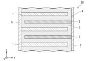
- FIG. 1 is a cross-sectional view of an all-solid-state battery according to a first embodiment
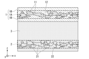
- FIG. 1 is an enlarged cross-sectional view of a characterizing portion of an all-solid-state battery according to a first embodiment
- FIG. 3 is an enlarged cross-sectional view of a characterizing portion of another example of the all-solid-state battery according to the first embodiment
- FIG. 4 is an enlarged cross-sectional view of a characteristic portion of the positive electrode of another example of the all-solid-state battery according to the first embodiment
- FIG. 4 is an enlarged cross-sectional view of a characteristic portion of the positive electrode of another example of the all-solid-state battery according to the first embodiment
- the stacking direction of the laminate 4 is the z-direction, one direction in the plane perpendicular to the z-direction is the x-direction, and the direction perpendicular to the x-direction and the z-direction is the y-direction.
- one direction of the z direction may be expressed as "up”, and the opposite direction as “down”. Up and down do not necessarily match the direction in which gravity is applied.
- FIG. 1 is a schematic cross-sectional view of an all-solid-state battery 10 according to this embodiment.
- the all-solid-state battery 10 has a laminate 4 and terminal electrodes 5 and 6 .
- the terminal electrodes 5 and 6 are in contact with the opposing surfaces of the laminate 4, respectively.
- the terminal electrodes 5 and 6 extend in the z-direction that intersects (perpendicularly) with the lamination surface of the laminate 4 .
- the laminate 4 has a positive electrode 1, a negative electrode 2, and a solid electrolyte layer 3.
- the laminate 4 is a sintered body in which the positive electrode 1, the negative electrode 2, and the solid electrolyte layer 3 are laminated and sintered.
- the number of layers of the positive electrode 1 and the negative electrode 2 is not particularly limited.
- the solid electrolyte layer 3 is present at least between the positive electrode 1 and the negative electrode 2 .
- One end of the positive electrode 1 is connected to the terminal electrode 5 .
- One end of the negative electrode 2 is connected to the terminal electrode 6 .
- the all-solid-state battery 10 is charged or discharged by transferring ions between the positive electrode 1 and the negative electrode 2 through the solid electrolyte layer 3 .
- a laminated battery is shown, but a wound battery may also be used.
- the all-solid-state battery 10 is used, for example, as a laminate battery, a prismatic battery, a cylindrical battery, a coin-shaped battery, a button-shaped battery, and the like. Further, the all-solid-state battery 10 may be an injection type in which the solid electrolyte layer 3 is dissolved or dispersed in a solvent.
- FIG. 2 is an enlarged view of the characterizing portion of the all-solid-state battery 10 according to the first embodiment.
- the positive electrode 1 has, for example, a positive electrode collector layer 1A and a positive electrode active material layer 1B.
- the positive electrode has, for example, a current collector layer containing Ag, and a positive electrode active material layer in contact with at least one main surface of the current collector layer.
- the positive electrode current collector layer 1A has, for example, a current collector 11 and a positive electrode active material 12 .
- the region between the xy plane passing through the uppermost portion of the current collector 11 and the xy plane passing through the lowermost portion thereof is regarded as the positive electrode current collector layer 1A.
- the current collector 11 is composed of a plurality of current collector particles. A plurality of current collector particles are connected to each other and electrically connected in the xy plane.
- the positive electrode 1 includes, as a current collector 11, a metal or alloy containing any one selected from the group consisting of Ag, Pd, Au, and Pt. These metals or alloys do not melt even when the laminate 4 is heated in the atmosphere and are not easily oxidized.
- the current collector 11 is AgPd alloy, Au, or Pt, for example.
- the positive electrode active material 12 is mixed together with the current collector 11 in the positive electrode current collector layer 1A.
- the positive electrode active material 12 is in contact with the current collector 11 .
- the transfer of electrons from the positive electrode active material 12 to the current collector 11 becomes smooth.
- the positive electrode active material 12 is the same as that contained in the positive electrode active material layer 1B described later.
- FIG. 2 shows an example in which the current collector 11 is composed of a plurality of current collector particles, it is not limited to this case.
- FIG. 3 is an enlarged view of a characterizing portion of another example of the all-solid-state battery according to the first embodiment.
- the current collector 11 may be in the form of a foil, a punched film, or an expanded form extending in the xy plane.
- a positive electrode active material layer included in the positive electrode is in contact with at least one main surface of the current collector layer.
- the positive electrode active material layer contains a positive electrode active material.
- the positive electrode active material layer may contain a conductive aid, a binder, and a solid electrolyte described later.
- the thickness of the positive electrode active material layer may be set within a range of 1 ⁇ m or more and 500 ⁇ m or less.
- the positive electrode active material layer 1B is formed on one side or both sides of the positive electrode current collector layer 1A.
- the positive electrode active material layer 1B contains a positive electrode active material.
- the positive electrode active material layer 1B may contain a conductive aid, a binder, and the solid electrolyte described above.
- the positive electrode active material layer 1B contains a solid electrolyte, the area between the xy plane passing through the top and the xy plane passing through the bottom of the positive electrode active material is regarded as the positive electrode active material layer 1B.
- the positive electrode active material is not particularly limited as long as it can reversibly progress the release and absorption of lithium ions and the desorption and insertion of lithium ions.
- positive electrode active materials used in known lithium ion secondary batteries can be used.
- Positive electrode active materials are, for example, composite transition metal oxides, transition metal fluorides, polyanions, transition metal sulfides, transition metal oxyfluorides, transition metal oxysulfides, and transition metal oxynitrides.
- the positive electrode active material is preferably lithium manganese composite oxide, lithium nickel composite oxide, lithium cobalt composite oxide, lithium vanadium composite oxide, lithium titanium composite oxide, manganese dioxide, titanium oxide, niobium oxide, vanadium oxide, Tungsten oxide and the like.
- the positive electrode active material is LiCoO 2 , LiMnO 2 , preferably LiCoO 2 . These compounds may have deviations from the stoichiometric composition.
- the positive electrode active material may be lithium cobaltate represented by Li x CoO 2 , where x varies in the range of 0.4 to 1.2 as the all-solid-state battery is charged and discharged. .
- a positive electrode active material that does not contain lithium can also be used as the positive electrode active material.
- These positive electrode active materials can be used by arranging a negative electrode active material doped with metallic lithium or lithium ions in advance on the negative electrode and starting the battery from discharging.
- non- lithium containing metal oxides MnO2 , V2O5 , etc.
- non-lithium containing metal sulfides MoS2, etc.
- non-lithium containing fluorides FeF3 , VF3, etc.
- the conductive aid is not particularly limited as long as it improves the electron conductivity in the positive electrode active material layer 1B, and known conductive aids can be used.
- Conductive agents include, for example, carbon-based materials such as graphite, carbon black, graphene, and carbon nanotubes, metals such as gold, platinum, silver, palladium, aluminum, copper, nickel, stainless steel, iron, and conductive oxides such as ITO. or mixtures thereof.
- the conductive aid may be in the form of powder or fiber.
- the binder bonds the positive electrode current collector layer 1A and the positive electrode active material layer 1B, the positive electrode active material layer 1B and the solid electrolyte layer 3, and various materials constituting the positive electrode active material layer 1B.
- the binder can be used within a range that does not impair the function of the positive electrode active material layer 1B.
- the binder may not be contained if unnecessary.
- the content of the binder in the positive electrode active material layer 1B is, for example, 0.5 to 30% by volume of the positive electrode active material layer. When the binder content is sufficiently low, the resistance of the positive electrode active material layer 1B is sufficiently low.
- binding material may be used as long as the above bonding is possible, and examples thereof include fluororesins such as polyvinylidene fluoride (PVDF) and polytetrafluoroethylene (PTFE).
- PVDF polyvinylidene fluoride
- PTFE polytetrafluoroethylene
- the binder for example, cellulose, styrene/butadiene rubber, ethylene/propylene rubber, polyimide resin, polyamideimide resin, or the like may be used.
- a conductive polymer having electronic conductivity or an ion-conductive polymer having ionic conductivity may be used as the binder. Examples of conductive polymers having electronic conductivity include polyacetylene.
- the binder since the binder also exhibits the function of a conductive additive, it is not necessary to add a conductive additive.
- the ion-conductive polymer having ion conductivity for example, one that conducts lithium ions can be used, and polymer compounds (polyether-based polymer compounds such as polyethylene oxide and polypropylene oxide, polyphosphazene etc.) with a lithium salt such as LiClO 4 , LiBF 4 , LiPF 6 or an alkali metal salt mainly composed of lithium.
- Polymerization initiators used for compositing include, for example, photopolymerization initiators or thermal polymerization initiators compatible with the above monomers. Properties required for the binder include oxidation/reduction resistance and good adhesiveness.
- FIGS. 4 and 5 are cross-sectional views of other examples of the positive electrode according to the first embodiment.
- the positive electrode shown in FIG. 4 has a positive electrode collector layer 1D and a positive electrode active material layer 1B.
- a positive electrode current collector layer 1 ⁇ /b>D has a current collector 11 , a positive electrode active material 12 and an oxide 13 .
- the oxide 13 is, for example, an oxide containing Ag, such as AgCoO 2 .
- the oxide 13 prevents oxidation of Ag contained in the current collector 11 .
- the cycle characteristics of the all-solid-state battery 10 are improved.
- the positive electrode shown in FIG. 5 has a positive electrode current collector layer 1E, an intermediate layer 1F, and a positive electrode active material layer 1B.
- Positive electrode current collector layer 1 ⁇ /b>E has current collector 11 and oxide 13 .
- Intermediate layer 1F is made of oxide 13 .
- the example shown in FIG. 5 corresponds to the case where the oxide 13 is thicker than the example shown in FIG.
- the oxide 13 prevents oxidation of Ag contained in the current collector 11 and improves cycle characteristics of the all-solid-state battery 10 .
- Solid electrolyte layer 3 contains a solid electrolyte.
- a solid electrolyte is a material in which ions can be moved by an externally applied electric field.
- the solid electrolyte layer 3 conducts lithium ions and inhibits movement of electrons.
- the solid electrolyte layer 3 is, for example, a sintered body obtained by sintering.
- the solid electrolyte layer 3 includes a first solid electrolyte having a ⁇ -Li 3 PO 4 type crystal structure.
- the first solid electrolyte is, for example, Li 3+x Si x P 1-x O 4 , Li 3+x Si x V 1-x O 4 , Li 3+x Ge x P 1-x O 4 , Li 3+x Ge x V 1-x O 4th place.
- x satisfies 0.2 ⁇ x ⁇ 0.8.
- x may satisfy 0.2 ⁇ x ⁇ 0.6.
- the first solid electrolyte may be a ternary lithium oxide containing Si, V, Ge, and the like.
- the negative electrode 2 has, for example, a current collector 21 and a second solid electrolyte 22 .
- the negative electrode 2 is defined between the xy plane passing through the uppermost part of the current collector 21 and the xy plane passing through the lowermost part thereof.
- the negative electrode 2 may contain a conductive aid, a binder, and the like.
- the current collector 21 is made of one or more selected from Ag and alloys containing Ag. Alloys containing Ag are, for example, AgPd alloys and AgLi alloys. When the current collector 21 is an alloy containing Ag, the volume ratio of Ag contained in the alloy is, for example, 80% or more. As shown in FIG. 3, the current collector 21 may be a foil extending in the xy plane, or may be punched or expanded.
- the negative electrode 2 generally includes composite transition metal oxides, transition metal fluorides, polyanions, transition metal sulfides, transition metal oxyfluorides, transition metal oxysulfides, transition metal oxynitrides, etc. that function as negative electrode active materials.
- the negative electrode 2 may contain only Ag among Ag and an alloy containing Ag.
- the negative electrode 2 may have only an alloy containing Ag among Ag and an alloy containing Ag.
- the negative electrode 2 may have both Ag and an alloy containing Ag among Ag and an alloy containing Ag.
- alloys containing Ag for example, Ag--Pd alloys and Ag--Li alloys can be used.
- the volume ratio (first volume ratio) of Ag or Ag alloy to the entire negative electrode 2 may be 45% or more and 95% or less.
- the volume ratio of Ag or Ag alloy may be 50% or more and 90% or less, 60% or more and 80% or less, or 80% or more.
- the second solid electrolyte 22 is the same as the first solid electrolyte included in the solid electrolyte layer 3 described above.
- the volume ratio (second volume ratio) of the second solid electrolyte 22 contained in the negative electrode 2 is, for example, 5% or more.
- the volume ratio of the second solid electrolyte 22 contained in the negative electrode 2 may be 5% or more and 55% or less, 10% or more and 50% or less, or 20% or more and 40% or less.
- the first solid electrolyte and the second solid electrolyte 22 may have the same constituent elements.
- the sum of the first volume ratio and the second volume ratio may be 95% or more and 100% or less.
- the current collector 21 and the second solid electrolyte 22 are in direct contact.
- a contact ratio between the current collector 21 and the second solid electrolyte 22 is, for example, 50% or more, preferably 80% or more.
- the contact ratio between the current collector 21 and the second solid electrolyte 22 is determined by extracting arbitrary 10 points of the current collector 21 from a cross-sectional image measured with a scanning electron microscope, and comparing the current collector 21 and the second solid electrolyte 22. is obtained by dividing the length of the contact portion of the current collector 21 by the outer circumference length of the current collector 21 .
- the laminated body 4 is produced.
- the laminate 4 is produced by, for example, a simultaneous firing method or a sequential firing method.
- the simultaneous firing method is a method of manufacturing the laminate 4 by stacking the materials forming each layer and then firing them all at once.
- the sequential firing method is a method in which firing is performed each time each layer is formed.
- the simultaneous firing method can produce the laminate 4 with fewer work steps than the sequential firing method.
- the laminate 4 produced by the simultaneous firing method is denser than the laminate 4 produced by the sequential firing method. A case of using the simultaneous firing method will be described below as an example.
- each material of the positive electrode current collector layer 1A, the positive electrode active material layer 1B, the solid electrolyte layer 3, and the negative electrode 2, which constitute the laminate 4 is made into a paste.
- the current collector 11 is coated with the oxide 13 and then pasted.
- the material forming the intermediate layer 1F is also pasted.
- the method of making each material into a paste is not particularly limited, and for example, a method of mixing the powder of each material with a vehicle to obtain a paste is used.
- the vehicle is a general term for medium in the liquid phase.
- Vehicles include solvents and binders.
- a green sheet is obtained by applying a paste prepared for each material onto a base material such as a PET (polyethylene terephthalate) film, drying it if necessary, and peeling off the base material.
- a base material such as a PET (polyethylene terephthalate) film
- the method of applying the paste is not particularly limited, and known methods such as screen printing, application, transfer, and doctor blade can be used.
- the green sheets produced for each material are stacked in a desired order and number of layers to produce a laminated sheet.
- alignment and cutting are performed as necessary. For example, when producing a parallel type or series-parallel type battery, alignment is performed so that the end face of the positive electrode current collector layer 1A and the end face of the negative electrode 2 do not match, and the respective green sheets are stacked.
- the laminated sheet may be produced by producing a positive electrode unit and a negative electrode unit, and laminating these units.
- the positive electrode unit is a laminate sheet in which a solid electrolyte layer 3, a positive electrode active material layer 1B, a positive electrode current collector layer 1A, and a positive electrode active material layer 1B are laminated in this order.
- an intermediate layer 1F is laminated between the positive electrode current collector layer 1A and the positive electrode active material layer 1B.
- the negative electrode unit is a laminated sheet in which the solid electrolyte layer 3 and the negative electrode 2 are laminated in order.
- the solid electrolyte layer 3 of the positive electrode unit and the negative electrode 2 of the negative electrode unit are laminated so as to face each other, or the positive electrode active material layer 1B of the positive electrode unit and the solid electrolyte layer 3 of the negative electrode unit face each other.
- the produced laminated sheets are collectively pressurized to increase the adhesion of each layer.
- Pressurization can be performed by, for example, a die press, a hot water isostatic press (WIP), a cold water isostatic press (CIP), an isostatic press, or the like. Pressurization is preferably performed while heating. The heating temperature during crimping is, for example, 40 to 95.degree.
- a dicing machine is used to cut the laminate after being pressed into chips. Then, by removing the binder from the chip and firing it, the laminated body 4 made of the sintered body is obtained.
- the binder removal process can be performed as a separate process from the firing process.
- the binder removal process is performed, the binder component contained in the chip is thermally decomposed before the firing process, and rapid decomposition of the binder component in the firing process can be suppressed.
- the binder removal step is performed, for example, by heating at a temperature of 300 to 800° C. for 0.1 to 10 hours in an air atmosphere.
- the atmosphere of the binder removal step is an oxygen partial pressure environment in which the materials composing the positive electrode, the negative electrode and the solid electrolyte are not oxidized or reduced, or the materials composing the positive electrode, the negative electrode and the solid electrolyte and the atmosphere.
- the gas species can be arbitrarily selected so that the gas does not react. For example, it may be carried out in a nitrogen atmosphere, an argon atmosphere, a nitrogen-hydrogen mixed atmosphere, a water vapor atmosphere, or a mixed atmosphere thereof.
- the firing process is performed by placing the chip on a ceramic table. Firing is performed, for example, by heating to 600 to 1000° C. in an air atmosphere.
- the firing time is, for example, 0.1 to 3 hours.
- the atmosphere of the sintering process is an oxygen partial pressure environment in which the materials composing the positive electrode, the negative electrode and the solid electrolyte are not or hardly oxidized and reduced.
- the gas species can be arbitrarily selected so that the gas does not react. For example, it may be carried out in a nitrogen atmosphere, an argon atmosphere, a nitrogen-hydrogen mixed atmosphere, a water vapor atmosphere, or a mixed atmosphere thereof.
- the sintered laminate 4 (sintered body) may be placed in a cylindrical container together with an abrasive such as alumina, and barrel-polished. This makes it possible to chamfer the corners of the laminate. Polishing may be performed using sandblasting. Sandblasting is preferable because it can grind only specific portions.
- Terminal electrodes 5 and 6 are formed on the side faces of the laminated body 4 thus produced, which face each other.
- the terminal electrodes 5 and 6 can be formed using means such as a sputtering method, a dipping method, a screen printing method, and a spray coating method.
- the all-solid-state battery 10 can be produced through the steps described above. When the terminal electrodes 5 and 6 are to be formed only on predetermined portions, the above process is performed after masking with tape or the like.
- the all-solid-state battery according to this embodiment has a high energy density. It is considered that this is because the potential of the negative electrode 2 becomes about 0 V (vs Li + /Li) because Ag and the alloy containing Ag of the negative electrode 2 function as a negative electrode active material.
- the output voltage of solid-state batteries increases.
- the energy amount of the all-solid-state battery 10 is obtained by multiplying the output voltage of the all-solid-state battery 10 by the capacity of the all-solid-state battery.
- the energy densities of the all-solid-state batteries 10 can be compared in terms of the amount of energy provided that the volumes of the all-solid-state batteries are the same. Therefore, the all-solid-state battery according to this embodiment has a high energy density.
- the negative electrode 2 contains lithium titanium oxide (potential of about 1.5 V (vs Li + /Li)) or the like, the above output voltage may not be achieved. Although the reason for this is not clear, it is thought that lithium titanium oxide gives and receives lithium ions preferentially depending on the combination of structures that function as the negative electrode active material.
- Example 1 Preparation of positive electrode paste
- Ethyl cellulose and dihydroterpineol were added to this powder and mixed.
- Ethyl cellulose is the binder and dihydroterpineol is the solvent.
- the positive electrode active material layer paste was prepared by adding ethyl cellulose and dihydroterpineol to LiMn 2 O 4 and mixing them.
- Li 2 CO 3 , SiO 2 and Li 3 PO 4 were used as starting materials and mixed in a molar ratio of 2:1:1.
- the mixture was wet mixed for 16 hours using a ball mill with water as a dispersion medium.
- the mixture was calcined at 950° C. for 2 hours to prepare Li 3.5 Si 0.5 P 0.5 O 4 .
- 100 parts by mass of this calcined powder, 100 parts by mass of ethanol, and 200 parts by mass of toluene were added to a ball mill and wet-mixed.
- 16 parts of a polyvinyl butyral-based binder and 4.8 parts by mass of benzyl butyl phthalate were added and mixed to prepare a solid electrolyte layer paste.
- a positive electrode unit and a negative electrode unit were produced by the following procedure.
- the positive electrode active material layer paste was printed with a thickness of 5 ⁇ m on the solid electrolyte layer sheet using screen printing.
- the printed positive electrode active material layer paste was dried at 80° C. for 5 minutes.
- the positive electrode current collector layer paste was printed with a thickness of 5 ⁇ m using screen printing.
- the printed positive electrode current collector layer paste was dried at 80° C. for 5 minutes.
- the positive electrode active material layer paste was printed again in a thickness of 5 ⁇ m on the dried positive electrode current collector layer paste by screen printing, and dried. After that, the PET film was peeled off.
- a positive electrode unit was obtained in which the positive electrode active material layer/positive electrode current collector layer/positive electrode active material layer were laminated in this order on the main surface of the solid electrolyte layer.
- a negative electrode paste was printed on the main surface of the solid electrolyte layer with a thickness of 10 ⁇ m.
- the printed negative electrode paste was dried at 80° C. for 5 minutes.
- a solid electrolyte unit was produced by stacking five solid electrolyte layer sheets. 50 electrode units (25 positive electrode units, 25 negative electrode units) were alternately stacked so as to sandwich the solid electrolyte unit. At this time, the units were staggered and stacked such that the odd-numbered electrode units extended only to one end surface and the even-numbered electrode units extended only to the opposite end surface. Six solid electrolyte layer sheets were stacked on top of this stacked unit. After that, this was molded by thermocompression bonding and then cut to produce a laminated chip. After that, the laminated chip was co-fired to obtain a laminated body. In the simultaneous firing, the temperature was raised to a firing temperature of 800° C. at a rate of temperature increase of 200° C./hour in an air atmosphere, held at that temperature for 2 hours, and naturally cooled after firing.
- An all-solid-state battery was produced by attaching terminal electrodes 5 and 6 to the sintered laminate (sintered body) by a known method.
- the all-solid-state battery after fabrication had the configuration shown in FIG.
- the volume ratio of each layer did not change between the paste state before sintering and the state after sintering.
- Ag can be present as Ag alone or contained as an element contained in an AgPd alloy.
- the capacity is the discharge capacity, and in an environment of 60 ° C., constant current charging (CC charging) is performed at a constant current of 100 ⁇ A until the battery voltage reaches 3.9 V. After that, the battery voltage reaches 0 V at a constant current of 100 ⁇ A.
- the discharge (CC discharge) cycle was repeated 10 cycles until the discharge capacity ( ⁇ Ah) at the 10th cycle was measured. Then, the amount of energy ( ⁇ Wh) was obtained from the product of the output voltage and the capacity of the all-solid-state battery.
- Examples 2-5" In Examples 2 to 5, the amount of Li 3.5 Si 0.5 P 0.5 O 4 added during the preparation of the negative electrode paste was changed, and the presence of Li 3.5 Si 0.5 P 0.5 O 4 changed the ratio. Other conditions were the same as in Example 1, and the same measurements as in Example 1 were performed.
- Examples 6-10 In Examples 6 to 10, the solid electrolyte used in preparing the solid electrolyte layer paste was changed to Li 3.5 Si 0.5 V 0.5 O 4 , and the solid electrolyte added to the negative electrode paste was Li 3.5. 5 Si 0.5 V 0.5 O 4 is different from each of Examples 1-5. Other conditions were the same as in Examples 1 to 5, and the same measurements as in Examples 1 to 5 were performed.
- Example 11 In Example 11, a powder obtained by mixing Ag, Pd, and LiCoO 2 in a volume ratio of 64:16:20 was used to prepare the positive electrode current collector layer paste. The difference from Example 2 is that LiCoO 2 was used instead of 2 O 4 . Other conditions were the same as in Example 2, and the same measurements as in Example 2 were performed.
- Example 12-15 Examples 12 to 15 differ from Example 13 in that the composition ratio of the solid electrolyte used in producing the solid electrolyte layer paste was changed.
- Example 12 uses Li 3.6 Si 0.6 P 0.4 O 4 as the solid electrolyte
- Example 13 uses Li 3.4 Si 0.4 P 0.6 O 4 as the solid electrolyte
- Example 14 uses Li 3.2 Si 0.2 P 0.8 O 4 was used as the solid electrolyte
- Li 3.1 Si 0.1 P 0.9 O 4 was used as the solid electrolyte in Example 15.
- Other conditions were the same as in Example 11, and the same measurements as in Example 11 were performed.
- Example 16 In Example 16, a powder obtained by mixing Ag and Li 3.5 Si 0.5 P 0.5 O 4 at a volume ratio of 80:20 was used when preparing the negative electrode paste. This example differs from Example 11 in that a powder obtained by mixing Ag and LiCoO 2 at a volume ratio of 80:20 was used when preparing the paste. Other conditions were the same as in Example 11, and the same measurements as in Example 11 were performed.
- Examples 17-23 In Examples 17 to 21), the amount of Li 3.5 Si 0.5 P 0.5 O 4 added during the preparation of the negative electrode paste was changed to obtain Li 3.5 Si 0.5 P 0.5 O 4 Changed the existence ratio. Other conditions were the same as in Example 11, and the same measurements as in Example 11 were performed.
- Example 24 Example 24 differs from Example 13 in that the composition of the solid electrolyte used in preparing the negative electrode paste was changed to Li 3.4 Si 0.4 P 0.6 O 4 .
- Example 25 differs from Example 29 in that the solid electrolyte used in producing the solid electrolyte paste was changed to Li 3.3 Si 0.3 P 0.7 O 4 .
- Example 26 differs from Example 12 in that the composition of the solid electrolyte used in preparing the negative electrode paste was changed to Li 3.6 Si 0.6 P 0.4 O 4 .
- Example 27-30 Examples 27 to 30 differ from Example 11 in that the composition ratio of the solid electrolyte used in preparing the negative electrode paste was changed.
- the solid electrolyte was Li3.4Si0.4P0.6O4
- the solid electrolyte was Li3.6Si0.6P0.4O4
- the solid electrolyte was Li3.3Si0.3P0.7O4
- the solid electrolyte was Li3.2Si0.2P0.8O4 .
- Other conditions were the same as in Example 11, and the same measurements as in Example 11 were performed.
- Example 31 differs from Example 11 in that the solid electrolyte used in preparing the negative electrode paste was changed to Li 3.5 Si 0.5 V 0.5 O 4 . Other conditions were the same as in Example 11, and the same measurements as in Example 11 were performed.
- Example 32 a Li—Ag alloy was added to the negative electrode current collector layer, and similar studies were conducted. However, the Li-Ag alloy was handled in a glove box with a dew point of -50 ° C., and the simultaneous firing was performed in an argon atmosphere at a heating rate of 1200 ° C./hour to a firing temperature of 800 ° C. for 20 minutes, and naturally cooled after firing. "Examples 32-33"
- Example 32 differs from Example 15 in that part of Ag was changed to a Li—Ag alloy (Li 3.1 Ag) when fabricating the negative electrode current collector layer. The amount of Li in the Li—Ag alloy was determined by quantitative analysis of X-ray diffraction (XRD). Other conditions were the same as in Example 1.
- XRD X-ray diffraction
- Example 33 differs from Example 15 in that part of Ag was changed to a Li—Ag alloy (Li 4.7 Ag) when fabricating the negative electrode current collector layer.
- the amount of Li in the Li—Ag alloy was determined by quantitative analysis of X-ray diffraction (XRD). Other conditions were the same as in Example 1.
- Comparative Example 1 Comparative Example 1 is different from Example 1 in that Li 3.5 Si 0.5 P 0.5 O 4 was not added when preparing the negative electrode paste.
- the volume ratio of Ag and Pd was 80:20.
- Other conditions were the same as in Example 1, and the same measurements as in Example 1 were performed.
- Comparative Example 2 Comparative Example 2 is different from Example 6 in that Li 3.5 Si 0.5 V 0.5 O 4 was not added when preparing the negative electrode paste.
- the volume ratio of Ag and Pd was 80:20.
- Other conditions were the same as in Example 6, and the same measurements as in Example 6 were performed.
- Comparative Example 3 the negative electrode is composed of a negative electrode current collector layer and a negative electrode active material layer, and this negative electrode unit is arranged on the main surface of the solid electrolyte layer, negative electrode active material layer/negative electrode current collector layer/negative electrode active material layer. are stacked in this order.
- AgPd alloy was used for the negative electrode current collector layer by using a powder obtained by mixing Ag and Pd at a volume ratio of 80:20 when preparing the paste.
- the negative electrode active material layer paste was prepared by adding ethyl cellulose and dihydroterpineol to Li 4 Ti 5 O 12 (Li 4/3 Ti 5/3 O 4 ) and mixing them. Other conditions were the same as in Example 1, and the same measurements as in Example 1 were performed.
- Comparative Example 4 Li 4 Ti 5 O 12 (Li 4/3 Ti 5/3 O 4 ) was added instead of Li 3.5 Si 0.5 P 0.5 O 4 when preparing the negative electrode paste. It differs from the second embodiment in that the Ag, Pd, and Li 4/3 Ti 5/3 O 4 were mixed at a volume ratio of 64:16:20 to prepare the negative electrode paste. Other conditions were the same as in Example 1, and the same measurements as in Example 1 were performed.
- Comparative Example 5 differs from Example 2 in that the composition ratio of the solid electrolyte used in producing the solid electrolyte layer paste was changed. Comparative Example 5 used Li 3.1 Si 0.1 P 0.9 O 4 as the solid electrolyte. The solid electrolyte had a Li 4 SiO 4 type crystal structure instead of a ⁇ -Li 3 PO 4 type crystal structure. Other conditions were the same as in Example 1, and the same measurements as in Example 1 were performed.
- Comparative Example 6 Comparative Example 6 is different from Example 16 in that the solid electrolyte layer is Li 4 Ti 5 O 12 and not the first solid electrolyte having a ⁇ -Li 3 PO 4 type crystal structure.
- Comparative Example 7 differs from Example 16 in that the solid electrolyte contained in the negative electrode is Li 4 Ti 5 O 12 and is not the second solid electrolyte having a ⁇ -Li 3 PO 4 type crystal structure.
- Comparative Example 8 the negative electrode is composed of a negative electrode current collector layer and a negative electrode active material layer, and this negative electrode unit is arranged on the main surface of the solid electrolyte layer, negative electrode active material layer/negative electrode current collector layer/negative electrode active material layer. are stacked in this order.
- AgPd alloy was used for the negative electrode current collector layer by using a powder obtained by mixing Ag and Pd at a volume ratio of 80:20 when preparing the paste.
- the negative electrode active material layer paste was prepared by adding ethyl cellulose and dihydroterpineol to Li 4 Ti 5 O 12 (Li 4/3 Ti 5/3 O 4 ) and mixing them. Other conditions were the same as in Example 16, and the same measurements as in Example 16 were performed.
- Examples 1-33 the amount of energy output was greater than in Comparative Examples 1-5. Since samples of the same size were prepared in Examples 1 to 33 and Comparative Examples 1 to 8, the output energy densities of Examples 1 to 33 were higher than those of Comparative Examples 1 to 8.
- Comparative Examples 1 and 2 the output voltage was high because the AgPd alloy functioned as the negative electrode active material. On the other hand, in Comparative Examples 1 and 2, the contact area between the solid electrolyte and the AgPd alloy was limited, and sufficient capacity was not obtained. As a result, it is considered that Comparative Examples 1 and 2 did not obtain a sufficient amount of energy compared to Examples 1-14.
- Comparative Examples 3 and 4 since the negative electrode contains Li 4/3 Ti 5/3 O 4 functioning as a negative electrode active material, Li 4/3 Ti 5/3 O 4 works preferentially over the AgPd alloy. , could not obtain enough output voltage. As a result, it is considered that Comparative Examples 3 and 4 did not obtain a sufficient amount of energy compared to Examples 1-14.
- Comparative Example 5 the solid electrolyte layer had a Li 4 SiO 4 type crystal structure instead of a ⁇ -Li 3 PO 4 type crystal structure.
- the Li 4 SiO 4 type crystal structure is inferior in ion conductivity to the ⁇ -Li 3 PO 4 type crystal structure, and sufficient lithium ions cannot be propagated to the negative electrode, resulting in a sufficient capacity. It is thought that there was not. As a result, it is considered that Comparative Example 5 was unable to obtain a sufficient amount of energy compared to Examples 1-14.
- the solid electrolyte layer had a first solid electrolyte having a ⁇ -Li 3 PO 4 type crystal structure, and the negative electrode had a second solid electrolyte having a ⁇ -Li 3 PO 4 type crystal structure. Since any one of the three points of having a solid electrolyte and having at least one selected from Ag and an alloy containing Ag in the negative electrode is not satisfied, the capacity and energy amount are significantly reduced. presumably decreased.
Landscapes
- Chemical & Material Sciences (AREA)
- Chemical Kinetics & Catalysis (AREA)
- Electrochemistry (AREA)
- General Chemical & Material Sciences (AREA)
- Engineering & Computer Science (AREA)
- Inorganic Chemistry (AREA)
- Manufacturing & Machinery (AREA)
- Materials Engineering (AREA)
- Physics & Mathematics (AREA)
- Condensed Matter Physics & Semiconductors (AREA)
- General Physics & Mathematics (AREA)
- Secondary Cells (AREA)
Priority Applications (4)
| Application Number | Priority Date | Filing Date | Title |
|---|---|---|---|
| US18/841,595 US20250167296A1 (en) | 2022-02-28 | 2022-09-30 | All-solid-state battery |
| CN202280092562.6A CN118749146A (zh) | 2022-02-28 | 2022-09-30 | 全固体电池 |
| JP2024502809A JPWO2023162318A1 (https=) | 2022-02-28 | 2022-09-30 | |
| EP22928839.4A EP4489170A4 (en) | 2022-02-28 | 2022-09-30 | COMPLETELY SOLID BATTERY |
Applications Claiming Priority (2)
| Application Number | Priority Date | Filing Date | Title |
|---|---|---|---|
| JP2022028957 | 2022-02-28 | ||
| JP2022-028957 | 2022-02-28 |
Publications (1)
| Publication Number | Publication Date |
|---|---|
| WO2023162318A1 true WO2023162318A1 (ja) | 2023-08-31 |
Family
ID=87765373
Family Applications (1)
| Application Number | Title | Priority Date | Filing Date |
|---|---|---|---|
| PCT/JP2022/036674 Ceased WO2023162318A1 (ja) | 2022-02-28 | 2022-09-30 | 全固体電池 |
Country Status (5)
| Country | Link |
|---|---|
| US (1) | US20250167296A1 (https=) |
| EP (1) | EP4489170A4 (https=) |
| JP (1) | JPWO2023162318A1 (https=) |
| CN (1) | CN118749146A (https=) |
| WO (1) | WO2023162318A1 (https=) |
Families Citing this family (2)
| Publication number | Priority date | Publication date | Assignee | Title |
|---|---|---|---|---|
| CN114402470A (zh) | 2019-09-13 | 2022-04-26 | Tdk株式会社 | 固体电解质层、全固体二次电池和它们的制造方法 |
| DE112021003367T5 (de) * | 2020-06-24 | 2023-05-04 | TDK Corporation | Festelektrolyt und festelektrolyt-akkumulator |
Citations (9)
| Publication number | Priority date | Publication date | Assignee | Title |
|---|---|---|---|---|
| WO2007135790A1 (ja) | 2006-05-23 | 2007-11-29 | Incorporated National University Iwate University | 全固体二次電池 |
| WO2008099508A1 (ja) | 2007-02-16 | 2008-08-21 | Namics Corporation | リチウムイオン二次電池、及び、その製造方法 |
| JP2011146202A (ja) * | 2010-01-13 | 2011-07-28 | Namics Corp | リチウムイオン二次電池 |
| JP2011198692A (ja) * | 2010-03-23 | 2011-10-06 | Namics Corp | リチウムイオン二次電池及びその製造方法 |
| JP2018181707A (ja) * | 2017-04-18 | 2018-11-15 | トヨタ自動車株式会社 | 負極合材、当該負極合材を含む負極、及び、当該負極を備える全固体リチウムイオン二次電池 |
| JP2018190695A (ja) * | 2017-04-28 | 2018-11-29 | 株式会社オハラ | 全固体電池 |
| WO2021149460A1 (ja) * | 2020-01-24 | 2021-07-29 | Tdk株式会社 | リチウムイオン二次電池 |
| JP2021132033A (ja) * | 2020-02-18 | 2021-09-09 | 三星電子株式会社Samsung Electronics Co., Ltd. | 全固体二次電池、及び全固体二次電池の製造方法 |
| JP2022028957A (ja) | 2018-06-19 | 2022-02-16 | 株式会社ササキコーポレーション | 燃焼装置の灰排出部構造 |
Family Cites Families (2)
| Publication number | Priority date | Publication date | Assignee | Title |
|---|---|---|---|---|
| JP4728385B2 (ja) * | 2008-12-10 | 2011-07-20 | ナミックス株式会社 | リチウムイオン二次電池、及び、その製造方法 |
| US11824155B2 (en) * | 2019-05-21 | 2023-11-21 | Samsung Electronics Co., Ltd. | All-solid lithium secondary battery and method of charging the same |
-
2022
- 2022-09-30 EP EP22928839.4A patent/EP4489170A4/en active Pending
- 2022-09-30 JP JP2024502809A patent/JPWO2023162318A1/ja active Pending
- 2022-09-30 WO PCT/JP2022/036674 patent/WO2023162318A1/ja not_active Ceased
- 2022-09-30 US US18/841,595 patent/US20250167296A1/en active Pending
- 2022-09-30 CN CN202280092562.6A patent/CN118749146A/zh active Pending
Patent Citations (9)
| Publication number | Priority date | Publication date | Assignee | Title |
|---|---|---|---|---|
| WO2007135790A1 (ja) | 2006-05-23 | 2007-11-29 | Incorporated National University Iwate University | 全固体二次電池 |
| WO2008099508A1 (ja) | 2007-02-16 | 2008-08-21 | Namics Corporation | リチウムイオン二次電池、及び、その製造方法 |
| JP2011146202A (ja) * | 2010-01-13 | 2011-07-28 | Namics Corp | リチウムイオン二次電池 |
| JP2011198692A (ja) * | 2010-03-23 | 2011-10-06 | Namics Corp | リチウムイオン二次電池及びその製造方法 |
| JP2018181707A (ja) * | 2017-04-18 | 2018-11-15 | トヨタ自動車株式会社 | 負極合材、当該負極合材を含む負極、及び、当該負極を備える全固体リチウムイオン二次電池 |
| JP2018190695A (ja) * | 2017-04-28 | 2018-11-29 | 株式会社オハラ | 全固体電池 |
| JP2022028957A (ja) | 2018-06-19 | 2022-02-16 | 株式会社ササキコーポレーション | 燃焼装置の灰排出部構造 |
| WO2021149460A1 (ja) * | 2020-01-24 | 2021-07-29 | Tdk株式会社 | リチウムイオン二次電池 |
| JP2021132033A (ja) * | 2020-02-18 | 2021-09-09 | 三星電子株式会社Samsung Electronics Co., Ltd. | 全固体二次電池、及び全固体二次電池の製造方法 |
Non-Patent Citations (1)
| Title |
|---|
| See also references of EP4489170A4 |
Also Published As
| Publication number | Publication date |
|---|---|
| US20250167296A1 (en) | 2025-05-22 |
| EP4489170A4 (en) | 2026-03-25 |
| CN118749146A (zh) | 2024-10-08 |
| EP4489170A1 (en) | 2025-01-08 |
| JPWO2023162318A1 (https=) | 2023-08-31 |
Similar Documents
| Publication | Publication Date | Title |
|---|---|---|
| JP7553352B2 (ja) | 全固体電池 | |
| JP7529571B2 (ja) | 全固体電池 | |
| JP7517995B2 (ja) | 全固体電池 | |
| CN109792080B (zh) | 全固体锂离子二次电池 | |
| JP6623542B2 (ja) | リチウムイオン二次電池 | |
| CN113169372B (zh) | 全固体二次电池 | |
| WO2022173002A1 (ja) | 固体電解質層及び全固体電池 | |
| US20250167296A1 (en) | All-solid-state battery | |
| CN113273015A (zh) | 全固体电池 | |
| WO2023162316A1 (ja) | 全固体電池 | |
| JP7812914B2 (ja) | 全固体二次電池 | |
| JP7812909B2 (ja) | 全固体電池 | |
| JP7850872B2 (ja) | 全固体電池 | |
| US20250167286A1 (en) | All-solid-state battery | |
| US20250167293A1 (en) | All-solid-state battery | |
| JP7829352B2 (ja) | 全固体電池 | |
| JP2023125397A (ja) | 全固体電池 | |
| WO2024135262A1 (ja) | 全固体電池 | |
| WO2024135831A1 (ja) | 全固体電池及び電子機器 | |
| CN118946936A (zh) | 固体电解质层及全固体二次电池 | |
| CN118765453A (zh) | 全固体二次电池 |
Legal Events
| Date | Code | Title | Description |
|---|---|---|---|
| 121 | Ep: the epo has been informed by wipo that ep was designated in this application |
Ref document number: 22928839 Country of ref document: EP Kind code of ref document: A1 |
|
| ENP | Entry into the national phase |
Ref document number: 2024502809 Country of ref document: JP Kind code of ref document: A |
|
| WWE | Wipo information: entry into national phase |
Ref document number: 18841595 Country of ref document: US Ref document number: 202280092562.6 Country of ref document: CN |
|
| WWE | Wipo information: entry into national phase |
Ref document number: 2022928839 Country of ref document: EP |
|
| NENP | Non-entry into the national phase |
Ref country code: DE |
|
| ENP | Entry into the national phase |
Ref document number: 2022928839 Country of ref document: EP Effective date: 20240930 |
|
| WWP | Wipo information: published in national office |
Ref document number: 18841595 Country of ref document: US |