WO2023153174A1 - 基板処理装置および監視方法 - Google Patents
基板処理装置および監視方法 Download PDFInfo
- Publication number
- WO2023153174A1 WO2023153174A1 PCT/JP2023/001713 JP2023001713W WO2023153174A1 WO 2023153174 A1 WO2023153174 A1 WO 2023153174A1 JP 2023001713 W JP2023001713 W JP 2023001713W WO 2023153174 A1 WO2023153174 A1 WO 2023153174A1
- Authority
- WO
- WIPO (PCT)
- Prior art keywords
- substrate
- unit
- polarizing filter
- captured image
- guard
- Prior art date
- Legal status (The legal status is an assumption and is not a legal conclusion. Google has not performed a legal analysis and makes no representation as to the accuracy of the status listed.)
- Ceased
Links
Images






Classifications
-
- G—PHYSICS
- G01—MEASURING; TESTING
- G01N—INVESTIGATING OR ANALYSING MATERIALS BY DETERMINING THEIR CHEMICAL OR PHYSICAL PROPERTIES
- G01N21/00—Investigating or analysing materials by the use of optical means, i.e. using sub-millimetre waves, infrared, visible or ultraviolet light
- G01N21/84—Systems specially adapted for particular applications
- G01N21/88—Investigating the presence of flaws or contamination
- G01N21/8806—Specially adapted optical and illumination features
-
- H—ELECTRICITY
- H04—ELECTRIC COMMUNICATION TECHNIQUE
- H04N—PICTORIAL COMMUNICATION, e.g. TELEVISION
- H04N23/00—Cameras or camera modules comprising electronic image sensors; Control thereof
- H04N23/70—Circuitry for compensating brightness variation in the scene
- H04N23/74—Circuitry for compensating brightness variation in the scene by influencing the scene brightness using illuminating means
-
- H—ELECTRICITY
- H10—SEMICONDUCTOR DEVICES; ELECTRIC SOLID-STATE DEVICES NOT OTHERWISE PROVIDED FOR
- H10P—GENERIC PROCESSES OR APPARATUS FOR THE MANUFACTURE OR TREATMENT OF DEVICES COVERED BY CLASS H10
- H10P72/00—Handling or holding of wafers, substrates or devices during manufacture or treatment thereof
- H10P72/06—Apparatus for monitoring, sorting, marking, testing or measuring
- H10P72/0606—Position monitoring, e.g. misposition detection or presence detection
-
- G—PHYSICS
- G01—MEASURING; TESTING
- G01N—INVESTIGATING OR ANALYSING MATERIALS BY DETERMINING THEIR CHEMICAL OR PHYSICAL PROPERTIES
- G01N21/00—Investigating or analysing materials by the use of optical means, i.e. using sub-millimetre waves, infrared, visible or ultraviolet light
- G01N21/84—Systems specially adapted for particular applications
- G01N21/88—Investigating the presence of flaws or contamination
-
- G—PHYSICS
- G01—MEASURING; TESTING
- G01N—INVESTIGATING OR ANALYSING MATERIALS BY DETERMINING THEIR CHEMICAL OR PHYSICAL PROPERTIES
- G01N21/00—Investigating or analysing materials by the use of optical means, i.e. using sub-millimetre waves, infrared, visible or ultraviolet light
- G01N21/84—Systems specially adapted for particular applications
- G01N21/88—Investigating the presence of flaws or contamination
- G01N21/8803—Visual inspection
-
- G—PHYSICS
- G01—MEASURING; TESTING
- G01N—INVESTIGATING OR ANALYSING MATERIALS BY DETERMINING THEIR CHEMICAL OR PHYSICAL PROPERTIES
- G01N21/00—Investigating or analysing materials by the use of optical means, i.e. using sub-millimetre waves, infrared, visible or ultraviolet light
- G01N21/84—Systems specially adapted for particular applications
- G01N21/88—Investigating the presence of flaws or contamination
- G01N21/8851—Scan or image signal processing specially adapted therefor, e.g. for scan signal adjustment, for detecting different kinds of defects, for compensating for structures, markings, edges
-
- G—PHYSICS
- G06—COMPUTING OR CALCULATING; COUNTING
- G06T—IMAGE DATA PROCESSING OR GENERATION, IN GENERAL
- G06T7/00—Image analysis
- G06T7/0002—Inspection of images, e.g. flaw detection
-
- G—PHYSICS
- G06—COMPUTING OR CALCULATING; COUNTING
- G06T—IMAGE DATA PROCESSING OR GENERATION, IN GENERAL
- G06T7/00—Image analysis
- G06T7/0002—Inspection of images, e.g. flaw detection
- G06T7/0004—Industrial image inspection
-
- H—ELECTRICITY
- H04—ELECTRIC COMMUNICATION TECHNIQUE
- H04N—PICTORIAL COMMUNICATION, e.g. TELEVISION
- H04N23/00—Cameras or camera modules comprising electronic image sensors; Control thereof
- H04N23/70—Circuitry for compensating brightness variation in the scene
- H04N23/72—Combination of two or more compensation controls
-
- H—ELECTRICITY
- H04—ELECTRIC COMMUNICATION TECHNIQUE
- H04N—PICTORIAL COMMUNICATION, e.g. TELEVISION
- H04N23/00—Cameras or camera modules comprising electronic image sensors; Control thereof
- H04N23/70—Circuitry for compensating brightness variation in the scene
- H04N23/75—Circuitry for compensating brightness variation in the scene by influencing optical camera components
-
- H—ELECTRICITY
- H10—SEMICONDUCTOR DEVICES; ELECTRIC SOLID-STATE DEVICES NOT OTHERWISE PROVIDED FOR
- H10P—GENERIC PROCESSES OR APPARATUS FOR THE MANUFACTURE OR TREATMENT OF DEVICES COVERED BY CLASS H10
- H10P50/00—Etching of wafers, substrates or parts of devices
-
- H—ELECTRICITY
- H10—SEMICONDUCTOR DEVICES; ELECTRIC SOLID-STATE DEVICES NOT OTHERWISE PROVIDED FOR
- H10P—GENERIC PROCESSES OR APPARATUS FOR THE MANUFACTURE OR TREATMENT OF DEVICES COVERED BY CLASS H10
- H10P52/00—Grinding, lapping or polishing of wafers, substrates or parts of devices
-
- H—ELECTRICITY
- H10—SEMICONDUCTOR DEVICES; ELECTRIC SOLID-STATE DEVICES NOT OTHERWISE PROVIDED FOR
- H10P—GENERIC PROCESSES OR APPARATUS FOR THE MANUFACTURE OR TREATMENT OF DEVICES COVERED BY CLASS H10
- H10P72/00—Handling or holding of wafers, substrates or devices during manufacture or treatment thereof
- H10P72/04—Apparatus for manufacture or treatment
- H10P72/0402—Apparatus for fluid treatment
- H10P72/0404—Apparatus for fluid treatment for general liquid treatment, e.g. etching followed by cleaning
-
- H—ELECTRICITY
- H10—SEMICONDUCTOR DEVICES; ELECTRIC SOLID-STATE DEVICES NOT OTHERWISE PROVIDED FOR
- H10P—GENERIC PROCESSES OR APPARATUS FOR THE MANUFACTURE OR TREATMENT OF DEVICES COVERED BY CLASS H10
- H10P72/00—Handling or holding of wafers, substrates or devices during manufacture or treatment thereof
- H10P72/04—Apparatus for manufacture or treatment
- H10P72/0402—Apparatus for fluid treatment
- H10P72/0406—Apparatus for fluid treatment for cleaning followed by drying, rinsing, stripping, blasting or the like
- H10P72/0411—Apparatus for fluid treatment for cleaning followed by drying, rinsing, stripping, blasting or the like for wet cleaning or washing
- H10P72/0414—Apparatus for fluid treatment for cleaning followed by drying, rinsing, stripping, blasting or the like for wet cleaning or washing using mainly spraying means, e.g. nozzles
-
- H—ELECTRICITY
- H10—SEMICONDUCTOR DEVICES; ELECTRIC SOLID-STATE DEVICES NOT OTHERWISE PROVIDED FOR
- H10P—GENERIC PROCESSES OR APPARATUS FOR THE MANUFACTURE OR TREATMENT OF DEVICES COVERED BY CLASS H10
- H10P72/00—Handling or holding of wafers, substrates or devices during manufacture or treatment thereof
- H10P72/06—Apparatus for monitoring, sorting, marking, testing or measuring
- H10P72/0604—Process monitoring, e.g. flow or thickness monitoring
-
- H—ELECTRICITY
- H10—SEMICONDUCTOR DEVICES; ELECTRIC SOLID-STATE DEVICES NOT OTHERWISE PROVIDED FOR
- H10P—GENERIC PROCESSES OR APPARATUS FOR THE MANUFACTURE OR TREATMENT OF DEVICES COVERED BY CLASS H10
- H10P72/00—Handling or holding of wafers, substrates or devices during manufacture or treatment thereof
- H10P72/50—Handling or holding of wafers, substrates or devices during manufacture or treatment thereof for positioning, orientation or alignment
- H10P72/53—Handling or holding of wafers, substrates or devices during manufacture or treatment thereof for positioning, orientation or alignment using optical controlling means
-
- H—ELECTRICITY
- H10—SEMICONDUCTOR DEVICES; ELECTRIC SOLID-STATE DEVICES NOT OTHERWISE PROVIDED FOR
- H10P—GENERIC PROCESSES OR APPARATUS FOR THE MANUFACTURE OR TREATMENT OF DEVICES COVERED BY CLASS H10
- H10P72/00—Handling or holding of wafers, substrates or devices during manufacture or treatment thereof
- H10P72/70—Handling or holding of wafers, substrates or devices during manufacture or treatment thereof for supporting or gripping
- H10P72/76—Handling or holding of wafers, substrates or devices during manufacture or treatment thereof for supporting or gripping using mechanical means, e.g. clamps or pinches
- H10P72/7604—Handling or holding of wafers, substrates or devices during manufacture or treatment thereof for supporting or gripping using mechanical means, e.g. clamps or pinches the wafers being placed on a susceptor, stage or support
- H10P72/7618—Handling or holding of wafers, substrates or devices during manufacture or treatment thereof for supporting or gripping using mechanical means, e.g. clamps or pinches the wafers being placed on a susceptor, stage or support characterised by a movable susceptor, stage or support, others than those only rotating on their own vertical axis, e.g. susceptors on a rotating carrousel
-
- H—ELECTRICITY
- H10—SEMICONDUCTOR DEVICES; ELECTRIC SOLID-STATE DEVICES NOT OTHERWISE PROVIDED FOR
- H10P—GENERIC PROCESSES OR APPARATUS FOR THE MANUFACTURE OR TREATMENT OF DEVICES COVERED BY CLASS H10
- H10P76/00—Manufacture or treatment of masks on semiconductor bodies, e.g. by lithography or photolithography
-
- H—ELECTRICITY
- H10—SEMICONDUCTOR DEVICES; ELECTRIC SOLID-STATE DEVICES NOT OTHERWISE PROVIDED FOR
- H10P—GENERIC PROCESSES OR APPARATUS FOR THE MANUFACTURE OR TREATMENT OF DEVICES COVERED BY CLASS H10
- H10P95/00—Generic processes or apparatus for manufacture or treatments not covered by the other groups of this subclass
-
- G—PHYSICS
- G01—MEASURING; TESTING
- G01N—INVESTIGATING OR ANALYSING MATERIALS BY DETERMINING THEIR CHEMICAL OR PHYSICAL PROPERTIES
- G01N21/00—Investigating or analysing materials by the use of optical means, i.e. using sub-millimetre waves, infrared, visible or ultraviolet light
- G01N21/84—Systems specially adapted for particular applications
- G01N21/88—Investigating the presence of flaws or contamination
- G01N21/8806—Specially adapted optical and illumination features
- G01N2021/8809—Adjustment for highlighting flaws
-
- G—PHYSICS
- G01—MEASURING; TESTING
- G01N—INVESTIGATING OR ANALYSING MATERIALS BY DETERMINING THEIR CHEMICAL OR PHYSICAL PROPERTIES
- G01N21/00—Investigating or analysing materials by the use of optical means, i.e. using sub-millimetre waves, infrared, visible or ultraviolet light
- G01N21/84—Systems specially adapted for particular applications
- G01N21/88—Investigating the presence of flaws or contamination
- G01N21/8806—Specially adapted optical and illumination features
- G01N2021/8835—Adjustable illumination, e.g. software adjustable screen
-
- G—PHYSICS
- G01—MEASURING; TESTING
- G01N—INVESTIGATING OR ANALYSING MATERIALS BY DETERMINING THEIR CHEMICAL OR PHYSICAL PROPERTIES
- G01N21/00—Investigating or analysing materials by the use of optical means, i.e. using sub-millimetre waves, infrared, visible or ultraviolet light
- G01N21/84—Systems specially adapted for particular applications
- G01N21/88—Investigating the presence of flaws or contamination
- G01N21/8806—Specially adapted optical and illumination features
- G01N2021/8848—Polarisation of light
Definitions
- the present disclosure relates to a substrate processing apparatus and monitoring method.
- various processing liquids such as pure water, photoresist liquid, and etching liquid are supplied to substrates to perform various substrate processing such as cleaning processing and resist coating processing. ing.
- a substrate processing apparatus in which a substrate holding section rotates a substrate in a horizontal position and a processing liquid is discharged from a nozzle onto the surface of the substrate.
- the nozzle ejects the processing liquid, for example, at a processing position facing the central portion of the upper surface of the substrate in the vertical direction.
- the processing liquid that has landed on the central portion of the substrate is subjected to centrifugal force due to the rotation of the substrate and spreads over the surface of the substrate.
- the substrate is processed by the processing liquid acting on the surface of the substrate.
- the camera is provided above the substrate holding portion.
- the camera captures an image of an imaging region including the substrate and the nozzle held by the substrate holder to generate a captured image.
- a reference image including nozzles is set in advance, and the positions of the nozzles are detected by performing matching processing between an image captured by a camera and the reference image.
- the substrate holding part includes a disk-shaped spin base provided below the substrate, and a plurality of chuck pins standing side by side in the circumferential direction along the periphery of the substrate on the upper surface of the spin base.
- the substrate holding section can hold the substrate, and by moving the plurality of chuck pins to the release position away from the periphery of the substrate. , the substrate is released.
- the substrate holding part cannot hold the substrate normally.
- the camera captures an image of an imaging area including the chuck pin, generates captured image data, and the image processing unit monitors the position of the chuck pin based on the captured image data.
- the camera generates a captured image when light from the imaging area is incident on its light receiving surface.
- the captured image includes a visualized image of reflected light from the imaging region, some of this reflected light is unnecessary for monitoring. For example, if the intensity of the reflected light from the imaging area is too high, the object in the imaging area is buried in the reflected light, and the visibility of the object in the captured image is reduced. As a notable example, if the intensity of the reflected light is too high and the pixel values saturate, the image of the object within that area will not be visible. There is a problem that such reflected light with too high intensity lowers the monitoring accuracy.
- the reflected light from the droplet enters the light receiving surface of the camera, and the droplet is also reflected in the captured image.
- the droplet is reflected in the captured image.
- Such droplets can also degrade monitoring accuracy.
- an object of the present disclosure is to provide a technology capable of suppressing the influence of unnecessary reflected light and monitoring an object to be monitored with higher accuracy.
- a first aspect is a substrate processing apparatus comprising a chamber, a substrate holding section that holds a substrate, an illumination section that irradiates an imaging area including a monitoring target in the chamber with illumination light, and a light from the imaging area. and a polarizing filter that transmits the light according to the polarization state of the light, and the polarizing filter is rotated to a rotational position according to the monitoring object, and the unnecessary reflected light according to the monitoring object is filtered out by the polarizing filter.
- a filter driving unit for reducing the noise a camera that captures an image of the imaging region through the polarizing filter to generate captured image data, and controls the filter driving unit and based on the captured image data generated by the camera and a control unit for monitoring the object to be monitored.
- a second aspect is the substrate processing apparatus according to the first aspect, further comprising a storage unit that stores in advance angle data indicating a rotational position of the polarizing filter corresponding to the object to be monitored, wherein the filter driving unit includes: Based on the angle data, the polarizing filter is rotated to the rotational position corresponding to the monitored object.
- a third aspect is the substrate processing apparatus according to the first aspect, wherein the control unit generates a The rotational position of the polarizing filter is determined based on the captured image data.
- a fourth aspect is the substrate processing apparatus according to the third aspect, wherein the controller controls the rotation based on the contrast of the plurality of captured image data or the number of contour lines in the plurality of captured image data. Determine position.
- a fifth aspect is the substrate processing apparatus according to any one of the first to fourth aspects, wherein the filter drive unit includes the imaging substrate used for monitoring a first monitored object as the monitored object.
- the polarizing filter is rotated to a first rotational position that reduces the unnecessary reflected light within the first determination area of the image data, and the control unit controls the captured image when the polarizing filter is positioned at the first rotational position.
- the first monitoring target object is monitored based on the first determination region of the data, and the filter driving unit controls the second monitoring target object of the captured image data used for monitoring the second monitoring target object as the monitoring target object.
- the control unit rotates the polarizing filter to a second rotational position that reduces the unnecessary reflected light within the determination area, and the control unit controls the second rotational position of the captured image data when the polarizing filter is positioned at the second rotational position.
- the second monitored object is monitored based on the determination area.
- a sixth aspect is the substrate processing apparatus according to any one of the first to fourth aspects, wherein when the first object exists within the imaging region, the filter drive unit is configured to remove the first object from the first object.
- the polarizing filter is rotated to a first rotational position that reduces the unnecessary reflected light, and the control unit determines that the polarizing filter is positioned at the first rotational position and the first object is present in the imaging area.
- the object to be monitored is monitored based on the captured image data when the image is captured, and the filter driving unit reduces the unnecessary reflected light from the second object when the second object exists within the imaging area.
- the polarizing filter is rotated to a second rotational position, and the controller controls the captured image data when the polarizing filter is positioned at the second rotational position and the second object exists in the imaging area. Based on this, the object to be monitored is monitored.
- a seventh aspect is the substrate processing apparatus according to any one of the first to sixth aspects, wherein the illumination unit is provided vertically above the imaging area, and the camera is a , provided outside the illumination unit with respect to the imaging area, and images the imaging area obliquely downward.
- An eighth aspect is the substrate processing apparatus according to any one of the first to seventh aspects, wherein the illumination section includes a plurality of unit illumination sections, and among the plurality of unit illumination sections, the illumination A unit illumination unit for irradiating light is switched according to the object to be monitored so that the effect of reducing the unnecessary reflected light by the polarizing filter is enhanced.
- a ninth aspect is a monitoring method, which is provided between an imaging region including an object to be monitored in a chamber containing a substrate holding part for holding a substrate and a camera, and polarizing light from the imaging region a polarization adjusting step of rotating the polarizing filter that transmits the light according to the state and reducing unnecessary reflected light according to the monitoring object with the polarizing filter; state, the camera captures an image of the imaging region through the polarizing filter to generate imaged image data; and a monitoring step of monitoring the object to be monitored based on the imaged image data generated by the camera. and
- the filter driver rotates the polarizing filter according to the monitored object, and the polarizing filter reduces unnecessary reflected light. Therefore, it is possible to reduce the influence of unnecessary reflected light on captured image data generated by the camera. Therefore, the control unit can monitor the monitored object with higher accuracy based on the captured image data.
- the rotational position can be determined by simple processing.
- contrast and the number of contour lines are increased by reducing unnecessary reflected light. Therefore, the influence of unnecessary reflected light on the captured image can be determined from the contrast or the number of contour lines.
- the fifth aspect it is possible to reduce unnecessary reflected light within the determination area of the monitored object according to the monitored object, and monitor the monitored object based on the determined area with reduced unnecessary reflected light. . Therefore, the object to be monitored can be monitored with high accuracy.
- the unnecessary reflected light according to the object existing within the imaging area is reduced, it is possible to appropriately reduce the influence of the unnecessary reflected light on the captured image.
- the effect of reducing unnecessary reflected light by the polarizing filter can be further enhanced.
- the effect of reducing unnecessary reflected light by the polarizing filter can be further enhanced according to the object to be monitored.
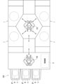
- FIG. 1 is a plan view schematically showing an example of a configuration of a substrate processing apparatus according to a first embodiment
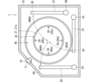
- FIG. 2 is a plan view schematically showing an example of the configuration of a processing unit according to the first embodiment
- FIG. 2 is a longitudinal sectional view schematically showing an example of the configuration of a processing unit according to the first embodiment
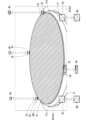
- FIG. It is a figure which shows roughly an example of a structure of a filter drive part
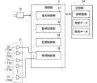
- 3 is a functional block diagram schematically showing an example of the internal configuration of a control unit
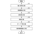
- FIG. 4 is a flow chart showing an example of the flow of substrate processing. It is a figure which shows an example of a captured image roughly. It is a figure which shows an example of a captured image roughly.
- FIG. 6 is a flowchart illustrating an example of monitoring processing
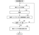
- 4 is a flowchart showing a specific example of a polarization adjustment process
- FIG. 5 is a diagram schematically showing the configuration of another embodiment of the processing unit
- FIG. 11 is a functional block diagram schematically showing an example of an internal configuration of a control section of a processing unit according to another embodiment
- 10 is a flowchart showing an example of monitoring processing according to another embodiment
- ordinal numbers such as “first” or “second” are used in the description below, these terms are used to facilitate understanding of the content of the embodiments. are used for convenience and are not limited to the orderings that can occur with these ordinal numbers.
- the expression is not only a geometrically exact representation of the shape, but also a similar effect, unless otherwise specified. In the range where is obtained, for example, a shape having unevenness or chamfering is also represented.
- the expression “comprising”, “comprises”, “comprises”, “includes” or “has” is used, the expression is not an exclusive expression excluding the presence of other elements.
- the expression “at least one of A, B and C” is used, the expression includes A only, B only, C only, any two of A, B and C, and A, B and all of C.
- FIG. 1 is a plan view schematically showing an example of the configuration of a substrate processing apparatus 100 according to the first embodiment.
- the substrate processing apparatus 100 is a single wafer processing apparatus that processes substrates W to be processed one by one.
- the substrate processing apparatus 100 performs liquid processing on the substrate W using a chemical solution and a rinse liquid such as pure water, and then performs a drying process.
- the substrate W is, for example, a semiconductor substrate and has a disk shape.
- the chemical solution examples include a mixed solution of ammonia and hydrogen peroxide (SC1), a mixed aqueous solution of hydrochloric acid and hydrogen peroxide (SC2), or a DHF solution (dilute hydrofluoric acid).
- SC1 ammonia and hydrogen peroxide
- SC2 mixed aqueous solution of hydrochloric acid and hydrogen peroxide
- DHF solution dilute hydrofluoric acid
- the substrate processing apparatus 100 includes a plurality of processing units 1, a load port LP, an indexer robot 102, a main transfer robot 103, and a controller 9.
- the load port LP is an interface section for loading/unloading the substrate W between the substrate processing apparatus 100 and the outside.
- a container also called a carrier
- a loadport LP can hold multiple carriers. Each substrate W is taken out from the carrier, processed by the substrate processing apparatus 100 as described later, and then housed in the carrier again.
- a carrier containing a plurality of processed substrates W is unloaded from the load port LP.
- the indexer robot 102 transports substrates W between each carrier held at the load port LP and the main transport robot 103 .
- the main transport robot 103 transports the substrate W between each processing unit 1 and the indexer robot 102 .
- the processing unit 1 performs liquid processing and drying processing on one substrate W. Twelve processing units 1 having the same configuration are arranged in the substrate processing apparatus 100 according to the present embodiment. Specifically, four towers each including three vertically stacked processing units 1 are arranged to surround the main transfer robot 103 . In FIG. 1, one of the three-tiered processing units 1 is schematically shown. The number of processing units 1 in the substrate processing apparatus 100 is not limited to 12, and may be changed as appropriate.
- the main transfer robot 103 is installed in the center of four towers in which the processing units 1 are stacked.
- the main transport robot 103 carries the substrate W to be processed received from the indexer robot 102 into each of the processing units 1 . Further, the main transport robot 103 carries out the processed substrate W from each processing unit 1 and passes it to the indexer robot 102 .
- the control unit 9 controls the operation of each component of the substrate processing apparatus 100 .
- One of the 12 processing units 1 mounted on the substrate processing apparatus 100 will be described below.
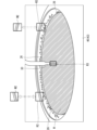
- FIG. 2 is a plan view schematically showing an example of the configuration of the processing unit 1 according to the first embodiment.
- FIG. 3 is a longitudinal sectional view schematically showing an example of the configuration of the processing unit 1 according to the first embodiment.
- the processing unit 1 includes a substrate holding section 20, a first nozzle 30, a second nozzle 60, a third nozzle 65, a guard section 40, a camera 70, a polarizing filter 73, and a and a filter driver 74 .
- the processing unit 1 also includes a chamber 10.
- the chamber 10 includes side walls 11 extending in the vertical direction, a ceiling wall 12 that closes the upper side of the space surrounded by the side walls 11, and a floor wall 13 that closes the lower side.
- a processing space is formed in a space surrounded by side walls 11 , ceiling wall 12 and floor wall 13 .
- a loading/unloading port for loading/unloading the substrate W by the main transport robot 103 and a shutter for opening/closing the loading/unloading port are provided on a part of the side wall 11 of the chamber 10 (not shown).
- Chamber 10 accommodates substrate holder 20 , first nozzle 30 , second nozzle 60 , third nozzle 65 and guard section 40 .
- the ceiling wall 12 of the chamber 10 is provided with a fan filter unit (FFU) for further purifying the air in the clean room in which the substrate processing apparatus 100 is installed and supplying it to the processing space in the chamber 10. 14 is attached.
- the fan filter unit 14 includes a fan and a filter (for example, a HEPA (High Efficiency Particulate Air) filter) for taking in the air in the clean room and sending it out into the chamber 10. form a flow.
- a punching plate with a large number of blowout holes may be provided directly below the ceiling wall 12 .
- the substrate holding part 20 holds the substrate W in a horizontal posture (a posture in which the normal is along the vertical direction) and rotates the substrate W around the rotation axis CX (see FIG. 3).
- the rotation axis CX is an axis extending in the vertical direction and passing through the center of the substrate W.
- the substrate holder 20 is also called a spin chuck. Note that FIG. 2 shows the substrate holding part 20 in a state in which no substrate is held.
- the substrate holding part 20 includes a disk-shaped spin base 21 provided in a horizontal posture.
- the outer diameter of the disk-shaped spin base 21 is slightly larger than the diameter of the circular substrate W held by the substrate holder 20 (see FIG. 3). Therefore, the spin base 21 has an upper surface 21a that vertically faces the entire lower surface of the substrate W to be held.
- a plurality of (four in this embodiment) chuck pins 26 are erected on the peripheral edge of the upper surface 21 a of the spin base 21 .
- a plurality of chuck pins 26 are arranged at equal intervals along the circumference corresponding to the periphery of the circular substrate W.
- Each chuck pin 26 is drivable between a holding position in contact with the peripheral edge of the substrate W and an open position away from the peripheral edge of the substrate W.
- a plurality of chuck pins 26 are interlocked and driven by a link mechanism (not shown) housed in the spin base 21 .
- the substrate holding part 20 can hold the substrate W in a horizontal posture close to the upper surface 21a above the spin base 21 by stopping the plurality of chuck pins 26 at respective holding positions (see FIG. 3). ), the holding of the substrate W can be released by stopping the plurality of chuck pins 26 at their respective open positions.
- the lower surface of the spin base 21 is connected to the upper end of the rotation shaft 24 extending along the rotation axis CX.
- a spin motor 22 that rotates a rotating shaft 24 is provided below the spin base 21 .
- the spin motor 22 rotates the spin base 21 in the horizontal plane by rotating the rotation shaft 24 around the rotation axis CX.
- the substrate W held by the chuck pins 26 also rotates around the rotation axis CX.
- a tubular cover member 23 is provided so as to surround the spin motor 22 and the rotary shaft 24.
- the cover member 23 has its lower end fixed to the floor wall 13 of the chamber 10 and its upper end reaching directly below the spin base 21 .
- a flange-like member 25 is provided at the upper end portion of the cover member 23, projecting substantially horizontally outward from the cover member 23, and further bending and extending downward.
- the first nozzle 30 discharges the processing liquid toward the substrate W to supply the substrate W with the processing liquid.
- the first nozzle 30 is attached to the tip of the nozzle arm 32 .
- the nozzle arm 32 extends horizontally and its base end is connected to the nozzle support column 33 .
- the nozzle support column 33 extends in the vertical direction and is rotatable about an axis in the vertical direction by a motor for driving an arm (not shown). As the nozzle support column 33 rotates, the first nozzle 30 moves between the nozzle processing position and the nozzle standby position in the space vertically above the substrate holder 20, as indicated by the arrow AR34 in FIG. to move in an arc.
- the nozzle processing position is a position where the first nozzle 30 discharges the processing liquid onto the substrate W, and is a position facing the central portion of the substrate W in the vertical direction, for example.
- the nozzle standby position is a position when the first nozzle 30 does not eject the processing liquid onto the substrate W, and is a position radially outside the peripheral edge of the substrate W, for example.
- the radial direction here is the radial direction about the rotation axis CX.
- FIG. 2 shows the first nozzles 30 positioned at the nozzle standby position
- FIG. 3 shows the first nozzles 30 positioned at the nozzle processing position.
- the first nozzle 30 is connected to a processing liquid supply source 36 via a supply pipe 34 .
- the processing liquid supply source 36 includes a tank that stores the processing liquid.
- a valve 35 is provided in the supply pipe 34 . By opening the valve 35 , the processing liquid is supplied from the processing liquid supply source 36 to the first nozzle 30 through the supply pipe 34 and discharged from the discharge port formed in the lower end surface of the first nozzle 30 .
- the first nozzle 30 may be configured to supply a plurality of types of treatment liquids (including at least pure water).
- the second nozzle 60 is attached to the tip of the nozzle arm 62 , and the base end of the nozzle arm 62 is connected to the nozzle support column 63 .
- a motor for driving an arm (not shown) rotates the nozzle support column 63, so that the second nozzle 60 moves in an arc in the space vertically above the substrate holder 20, as indicated by an arrow AR64.
- the third nozzle 65 is attached to the tip of the nozzle arm 67 and the base end of the nozzle arm 67 is connected to the nozzle support column 68 .
- a motor for driving an arm rotates the nozzle support column 68, so that the third nozzle 65 moves in an arcuate space vertically above the substrate holder 20, as indicated by an arrow AR69. .
- Each of the second nozzle 60 and the third nozzle 65 is also connected to a processing liquid supply source (not shown) through a supply pipe (not shown) in the same manner as the first nozzle 30 .
- Each supply pipe is provided with a valve, and the supply/stop of the treatment liquid is switched by opening and closing the valve. Note that the number of nozzles provided in the processing unit 1 is not limited to three, and may be one or more.
- the processing unit 1 causes the substrate W to be rotated by the substrate holding part 20 and ejects the processing liquid toward the upper surface of the substrate W from the first nozzle 30, for example.
- the processing liquid that has landed on the upper surface of the substrate W receives centrifugal force due to the rotation, spreads over the upper surface of the substrate W, and scatters from the peripheral edge of the substrate W.
- the upper surface of the substrate W can be processed according to the type of the processing liquid.
- the guard part 40 is a member for receiving the processing liquid that scatters from the periphery of the substrate W.
- the guard section 40 has a tubular shape surrounding the substrate holding section 20, and includes, for example, a plurality of guards that can be raised and lowered independently of each other.
- a guard may also be referred to as a processing cup.
- inner guard 41, middle guard 42 and outer guard 43 are shown as a plurality of guards.
- Each of the guards 41 to 43 surrounds the substrate holder 20 and has a shape substantially rotationally symmetrical with respect to the rotation axis CX.
- the inner guard 41 integrally includes a bottom portion 44, an inner wall portion 45, an outer wall portion 46, a first guide portion 47, and an intermediate wall portion 48.
- the bottom portion 44 has an annular shape in plan view.
- the inner wall portion 45 and the outer wall portion 46 have a cylindrical shape and are erected on the inner and outer peripheral edges of the bottom portion 44, respectively.
- the first guide portion 47 includes a cylindrical tubular portion 47a erected on the bottom portion 44 between the inner wall portion 45 and the outer wall portion 46, and a cylindrical portion 47a extending vertically upward from the upper end of the tubular portion 47a along the rotation axis CX. and an inclined portion 47b that approaches.
- the middle wall portion 48 has a cylindrical shape and is erected on the bottom portion 44 between the first guide portion 47 and the outer wall portion 46 .
- the disposal groove 49 is an annular groove formed by the inner wall portion 45 , the first guide portion 47 and the bottom portion 44 .
- the disposal groove 49 is connected to an exhaust liquid mechanism (not shown) for discharging the processing liquid and forcibly exhausting the inside of the disposal groove 49 .
- the middle guard 42 integrally includes a second guide portion 52 and a cylindrical processing liquid separation wall 53 connected to the second guide portion 52 .
- the second guide portion 52 has a cylindrical tubular portion 52a and an inclined portion 52b that approaches the rotation axis CX as it goes vertically upward from the upper end of the tubular portion 52a.
- the inclined portion 52b is positioned vertically above the inclined portion 47b of the inner guard 41, and is provided so as to overlap the inclined portion 47b in the vertical direction.
- the tubular portion 52 a is accommodated in the annular inner recovery groove 50 .
- the inner recovery groove 50 is a groove formed by the first guide portion 47 , the middle wall portion 48 and the bottom portion 44 .
- the processing liquid from the periphery of the substrate W is received by the inner peripheral surface of the second guide portion 52, flows down along the inner peripheral surface, and is received by the inner recovery groove 50. .
- the processing liquid separation wall 53 has a cylindrical shape, and its upper end is connected to the second guide portion 52 .
- the processing liquid separation wall 53 is accommodated in the annular outer recovery groove 51 .
- the outer recovery groove 51 is a groove formed by the inner wall portion 48 , the outer wall portion 46 and the bottom portion 44 .
- the outer guard 43 is located outside the inner guard 42 and functions as a third guide section that guides the processing liquid to the outer recovery groove 51 .
- the outer guard 43 integrally includes a cylindrical tubular portion 43a and an inclined portion 43b that approaches the rotation axis CX as it goes vertically upward from the upper end of the tubular portion 43a.
- the cylindrical portion 43a is accommodated in the outer recovery groove 51, and the inclined portion 43b is positioned vertically above the inclined portion 52b and provided so as to vertically overlap the inclined portion 52b.
- the inner recovery groove 50 and the outer recovery groove 51 are connected with a recovery mechanism (both not shown) for recovering the processing liquid into a recovery tank provided outside the processing unit 1 .
- the guards 41 to 43 can be raised and lowered by a guard raising and lowering mechanism 55.
- a guard lifting mechanism 55 lifts and lowers the guards 41 to 43 between the respective guard processing positions and guard standby positions so that the guards 41 to 43 do not collide with each other.
- the guard processing position is a position where the upper peripheral edge of the target guard to be lifted is above the upper surface of the substrate W
- the guard standby position is a position where the upper peripheral edge of the target guard is above the upper surface 21 a of the spin base 21 . is also at the lower position.
- the upper end peripheral portion referred to here is an annular portion that forms the upper end opening of the target guard.
- the guards 41-43 are positioned at the guard standby position.
- the guard lifting mechanism 55 has, for example, a ball screw mechanism and a motor or an air cylinder.
- the partition plate 15 is provided around the guard part 40 so as to vertically partition the inner space of the chamber 10 .
- the partition plate 15 may have a through hole and a notch (not shown) penetrating in the thickness direction. through holes are formed.
- the outer peripheral edge of the partition plate 15 is connected to the side wall 11 of the chamber 10 .
- the inner peripheral edge of the partition plate 15 surrounding the guard portion 40 is formed in a circular shape with a diameter larger than the outer diameter of the outer guard 43 . Therefore, the partition plate 15 does not hinder the lifting of the outer guard 43 .
- an exhaust duct 18 is provided in the vicinity of the floor wall 13, which is part of the side wall 11 of the chamber 10. As shown in FIG. The exhaust duct 18 is communicatively connected to an exhaust mechanism (not shown). Of the clean air that has flowed down inside the chamber 10, the air that has passed between the guard portion 40 and the partition plate 15 is discharged from the exhaust duct 18 to the outside of the apparatus.
- the camera 70 is used to monitor the state of objects to be monitored within the chamber 10 .
- the monitored object includes at least one of the substrate holding section 20, the first nozzle 30, the second nozzle 60, the third nozzle 65 and the guard section 40, for example.
- the camera 70 captures an image of an imaging area including an object to be monitored, generates captured image data (hereinafter simply referred to as a captured image), and outputs the captured image to the control unit 9 .
- the control unit 9 monitors the state of the monitored object based on the captured image, as will be described in detail later.
- the camera 70 includes a solid-state imaging device such as a CCD (Charge Coupled Device) or CMOS (Complementary Metal Oxide Semiconductor) and an optical system such as a lens.
- a solid-state imaging device such as a CCD (Charge Coupled Device) or CMOS (Complementary Metal Oxide Semiconductor)
- an optical system such as a lens.
- the camera 70 is installed at an imaging position vertically above the substrate W held by the substrate holding part 20 .
- the imaging position is set vertically above the partition plate 15 and radially outside the guard section 40 .
- the radial direction here is the radial direction about the rotation axis CX.
- the side wall 11 of the chamber 10 is formed with a concave portion (hereinafter referred to as a concave wall portion 111) for housing the camera 70 therein.
- the recessed wall portion 111 has a shape that is recessed outward with respect to other portions of the side wall 11 .
- the camera 70 is housed inside the concave wall portion 111 .
- a transparent member 72 is provided in front of the camera 70 in the imaging direction.
- the transparent member 72 has high translucency with respect to the wavelength of light detected by the camera 70 . Therefore, the camera 70 can take an image of the imaging area within the processing space through the transparent member 72 . In other words, the transparent member 72 is provided between the camera 70 and the imaging area.
- the transmittance of the transparent member 72 in the detection wavelength range of the camera 70 is, for example, 60% or more, preferably 80% or more.
- the transparent member 72 is made of, for example, a transparent material such as quartz glass.
- the transparent member 72 has a plate-like shape and forms a housing space for the camera 70 together with the concave wall portion 111 of the side wall 11 .
- the imaging area of the camera 70 includes, for example, part of the substrate holding section 20 and the guard section 40 .
- the camera 70 images an imaging area obliquely downward from the imaging position.
- the imaging direction of the camera 70 is inclined vertically downward from the horizontal direction.
- the lighting section 71 is provided at a position vertically above the partition plate 15 .
- the lighting section 71 is provided radially outside the guard section 40 in plan view, and as a more specific example, is provided inside the concave wall section 111 .
- the illumination unit 71 includes a light source such as a light emitting diode, and irradiates the imaging area with illumination light.
- the control unit 9 may control the illumination unit 71 so that the illumination unit 71 illuminates the imaging area when the camera 70 takes an image. Illumination light from the illumination unit 71 is transmitted through the transparent member 72 and irradiated into the processing space.
- a polarizing filter 73 is provided between the camera 70 and the imaging area.
- the polarizing filter 73 is also provided inside the concave wall portion 111 .
- the polarizing filter 73 transmits the light from the imaging area according to the polarization state of the light.
- the absorption axis and the polarization axis of the polarizing filter 73 are orthogonal to each other, and the polarizing filter 73 absorbs the polarized component along the absorption axis of the light incident on itself, and absorbs the polarized component along the polarization axis. pass through.
- the polarizing filter 73 may be a circular polarizing filter. Light reflected by the imaging area enters the light receiving surface of the camera 70 through the polarizing filter 73 . That is, the camera 70 images the imaging area through the polarizing filter 73 .
- the filter drive unit 74 rotates the polarizing filter 73 around the rotation axis Q2 along its optical axis. As a result, the absorption axis of the polarizing filter 73 rotates around the rotation axis Q2.
- the rotation axis Q2 is also the direction along the imaging direction of the camera 70 .
- FIG. 4 is a diagram schematically showing an example of the configuration of the filter driving section 74.
- Filter drive unit 74 includes a case 741 , a rotation holding member 742 and a rotation mechanism 743 .
- the case 741 has a ring-shaped outer shape surrounding the rotation axis Q2.
- the rotation holding member 742 holds the periphery of the polarizing filter 73 and is housed in the case 741 so as to be rotatable around the rotation axis Q2.
- the rotation mechanism 743 rotates the rotation holding member 742 with respect to the case 741 .
- the rotating mechanism 743 includes a power transmission mechanism 744 and a motor 745 . Motor 745 is controlled by controller 9 .
- the motor 745 transmits rotational force to the rotation holding member 742 via the power transmission mechanism 744 to rotate the rotation holding member 742 with respect to the case 741 .
- the power transmission mechanism 744 has, for example, an external gear that meshes with a plurality of tooth profiles formed on the outer peripheral surface of the rotation holding member 742, and the motor 745 rotates the external gear to mesh with the external gear.
- Rotating holding member 742 rotates.
- the rotation mechanism 743 rotates the rotation holding member 742 to rotate the polarizing filter 73 held by the rotation holding member 742 around the rotation axis Q2.
- the filter driving section 74 rotates the polarizing filter 73 around the rotation axis Q2 in accordance with the unnecessary reflected light from the imaging area, and the polarizing filter 73 reduces the unnecessary reflected light.
- the unnecessary reflected light referred to here is the reflected light from the imaging area, and is the reflected light that causes a decrease in the monitoring accuracy of the monitored object. A specific example of the unnecessary reflected light will be described later.
- control unit 9 includes a data processing unit such as a CPU that performs various arithmetic processing, a non-temporary storage unit such as a ROM (Read Only Memory) that stores basic programs, and various information. It is configured with a temporary storage unit such as a RAM (Random Access Memory) that is a readable and writable memory for storage.
- a data processing unit such as a CPU that performs various arithmetic processing
- non-temporary storage unit such as a ROM (Read Only Memory) that stores basic programs, and various information. It is configured with a temporary storage unit such as a RAM (Random Access Memory) that is a readable and writable memory for storage.
- RAM Random Access Memory
- Each operation mechanism of the substrate processing apparatus 100 is controlled by the control unit 9 by the CPU of the control unit 9 executing a predetermined processing program, and processing in the substrate processing apparatus 100 proceeds.
- the control unit 9 may be implemented by a dedicated hardware circuit that does not require software to implement its functions
- FIG. 5 is a functional block diagram schematically showing an example of the internal configuration of the control section 9.
- the controller 9 includes a polarization controller 91 , a monitoring processor 92 and a process controller 93 .
- the polarization control unit 91 outputs a control signal to the filter driving unit 74 (more specifically, the motor 745) to cause the filter driving unit 74 to rotate the polarizing filter 73. A detailed operation of the polarization control section 91 will be described later.
- the monitoring processing unit 92 monitors the state of the monitored object based on the captured image from the camera 70 . Detailed operations of the monitoring processing unit 92 will also be described later.
- the processing control section 93 controls each component of the processing unit 1 . More specifically, the processing control unit 93 controls the spin motor 22, various valves such as the valve 35, an arm drive motor for rotating each of the nozzle support columns 33, 63, 68, the guard lifting mechanism 55, the fan filter, and the like. Controls unit 14 and camera 70 .
- the processing unit 1 can process the substrate W by the processing control unit 93 controlling these configurations according to a predetermined procedure.
- FIG. 6 is a flow chart showing an example of the flow of substrate processing.
- the guards 41 to 43 respectively stop at the guard standby positions, and the nozzles 30, 60 and 65 respectively stop at the nozzle standby positions.
- the control unit 9 controls each component to execute a predetermined operation described later, the following description will be given using each component itself as the subject of the operation.
- the main transport robot 103 loads an unprocessed substrate W into the processing unit 1, and the substrate holding section 20 holds the substrate W (step S1: loading and holding step). Since the guard section 40 is initially stopped at the guard standby position, collision between the hand of the main transport robot 103 and the guard section 40 can be avoided when the substrate W is loaded.
- the plurality of chuck pins 26 hold the substrate W by moving the plurality of chuck pins 26 to respective holding positions.
- step S2 rotation start step
- the spin motor 22 rotates the spin base 21 to rotate the substrate W held by the substrate holder 20 .
- the processing unit 1 performs various liquid processing on the substrate W (step S3: liquid processing step).
- the processing unit 1 performs chemical processing.
- the guard raising/lowering mechanism 55 raises the guard corresponding to the chemical among the guards 41 to 43 to the guard processing position.
- the guard for chemical solution is not particularly limited, it may be the outer guard 43, for example.
- the guard lifting mechanism 55 stops the inner guard 41 and the middle guard 42 at their respective guard standby positions, and raises the outer guard 43 to the guard processing position.
- the processing unit 1 supplies the chemical solution to the substrate W.
- the first nozzle 30 supplies the processing liquid.
- the arm drive motor moves the first nozzle 30 to the nozzle processing position, the valve 35 opens, and the chemical liquid is discharged from the first nozzle 30 toward the substrate W.
- the chemical solution acts on the upper surface of the substrate W, and the substrate W is subjected to a treatment (for example, cleaning treatment) according to the chemical solution.
- the chemical liquid scattered from the peripheral edge of the substrate W is received by the inner peripheral surface of the guard section 40 (for example, the outer guard 43).
- the processing unit 1 stops supplying the chemical solution.
- the processing unit 1 performs a rinsing process on the substrate W.
- the guard lifting mechanism 55 adjusts the lifting state of the guard section 40 as necessary. That is, when the guard for the rinse liquid is different from the guard for the chemical liquid, the guard elevating mechanism 55 moves the guard corresponding to the rinse liquid among the guards 41 to 43 to the guard processing position.
- the rinse liquid guard is not particularly limited, it may be the inner guard 41 . In this case, the guard elevating mechanism 55 raises the guards 41 to 43 to their respective guard processing positions.
- the first nozzle 30 discharges the first rinse liquid toward the upper surface of the substrate W.
- the first rinse liquid is pure water, for example.
- the first rinse spreads over the upper surface of the substrate W during rotation, sweeps away the chemical solution on the substrate W, and scatters from the periphery of the substrate W.
- the processing liquid (mainly the rinsing liquid) scattered from the periphery of the substrate W is received by the inner peripheral surface of the guard section 40 (for example, the inner guard 41).
- the processing unit 1 stops supplying the first rinse liquid.
- the processing unit 1 may supply a volatile second rinse such as isopropyl alcohol having high volatility to the substrate W as necessary. If the guard for the second rinse liquid is different from the guard for the first rinse liquid, the guard lifting mechanism 55 moves the guard corresponding to the second rinse liquid among the guards 41 to 43 to the guard processing position. should be moved. After the rinse process is completed, the first nozzle 30 moves to the nozzle standby position.
- a volatile second rinse such as isopropyl alcohol having high volatility
- step S4 drying process
- the spin motor 22 increases the rotation speed of the substrate W to dry the substrate W (so-called spin dry).
- the processing liquid that scatters from the periphery of the substrate W is received by the inner peripheral surface of the guard section 40 .
- the spin motor 22 stops the rotation of the substrate W when the drying process is sufficiently performed.
- step S5 guard lowering step. That is, the guard lifting mechanism 55 lowers the guards 41 to 43 to their respective guard standby positions.
- step S6 holding release carry-out process
- the substrate W is processed by appropriately operating various components in the processing unit 1 .
- the substrate holding part 20 holds the substrate W or releases the holding.
- the first nozzle 30 moves between the nozzle processing position and the nozzle waiting position, and discharges the processing liquid toward the substrate W at the nozzle processing position.
- Each of the guards 41 to 43 of the guard section 40 moves to a height position corresponding to each process.
- the processing unit 1 monitors at least one of the above components as a monitoring target based on the captured image from the camera 70 .
- step S1 if the guard section 40 has not moved to the guard standby position, there is a possibility that the hand of the main transport robot 103 will collide with the guard section 40 when the substrate W is loaded. Therefore, it is desirable to monitor the position of the guard portion 40 during the holding and loading process.
- the substrate holding unit 20 cannot properly hold the substrate W if the chuck pins 26 cannot move to the holding position after the substrate W is loaded in the holding and loading process. Therefore, it is also desirable to monitor the positions of the chuck pins 26 of the substrate holder 20 after the substrate W is loaded in the holding and loading step.
- step S3 if the first nozzle 30 cannot appropriately discharge the processing liquid, the substrate W may be processed excessively or insufficiently. Therefore, it is also desired to monitor the discharge state of the first nozzle 30 in the liquid processing process.
- the guard section 40 cannot be moved to the guard processing position appropriately, the guard corresponding to the processing liquid cannot receive the processing liquid. Therefore, it is also desired to monitor the position of the guard part 40 in the liquid processing process.
- step S5 if the guard section 40 is not properly moved to the guard standby position, in the subsequent holding release carrying out process (step S6), the hand of the main transport robot 103 moves to the guard section 40. may conflict with Therefore, it is also desirable to monitor the position of the guard portion 40 during the guard lowering process.
- FIG. 7 and 8 are diagrams schematically showing examples of captured images.
- the substrate holding section 20 holds the substrate W, and the guard section 40 is stopped at the guard standby position.
- This captured image is obtained, for example, by capturing an image of the imaging area with the camera 70 in the carry-in holding process (step S1) or the guard lowering process (step S5).
- the substrate holding part 20 holds the substrate W, only the outer guard 43 is stopped at the guard processing position, and the first nozzle 30 is stopped at the nozzle processing position.
- This captured image is obtained, for example, by capturing an image of the imaging region with the camera 70 in the liquid treatment process.
- the captured image of FIG. 7 includes the entire upper surface of the substrate W held by the substrate holding unit 20, and the captured image of FIG. 8 includes the entire upper peripheral edge of the outer guard 43 positioned at the guard processing position. It is included.
- the camera 70 is installed so that the entire upper surface of the substrate W and the entire upper peripheral edge of the outer guard 43 positioned at the guard processing position are included in the imaging area.
- the camera 70 images the imaging area obliquely downward, the upper surface of the substrate W, which is circular in plan view, and the upper edge edge of the outer guard 43 have an elliptical shape in the captured image.
- a plurality of chuck pins 26 are included in the captured image, and as illustrated in FIG. 30 is also included in the captured image.
- the captured image also includes the second nozzle 60 and the third nozzle 65 positioned at the nozzle processing position. Therefore, the monitoring processing unit 92 can monitor the states of the substrate holding unit 20, the first nozzle 30, the second nozzle 60, the third nozzle 65, and the guard unit 40 based on the captured image.
- the monitoring processing unit 92 does not always need to monitor all of these monitoring objects.
- the monitoring processor 92 may monitor the ejection state of the first nozzle 30 in the liquid processing step (step S3), and does not need to monitor in other steps.
- the monitoring processing unit 92 does not need to use the entire area of the captured image. That is, the monitoring processing unit 92 monitors the state of the monitored object based on the determination area including the monitored object.
- the captured image in FIG. 7 shows a pin determination region R1 and a guard determination region R2.
- the pin determination area R1 is an area used for monitoring the positions of the chuck pins 26 of the substrate holder 20 .
- the captured image since the captured image includes four chuck pins 26, four pin determination regions R1 are set in advance corresponding to the four chuck pins 26, respectively.
- Each pin determination region R1 is set to a region including at least a portion of the chuck pin 26 positioned at the holding position.
- each pin determination region R1 is set so as to include a portion of the chuck pin 26 that comes into contact with the peripheral edge of the substrate W. As shown in FIG.
- the monitoring processing unit 92 monitors the position of the chuck pin 26 based on the pin determination area R1.
- a reference image M1 for monitoring the position of the chuck pin 26 is stored in the storage unit 94 in advance.
- the reference image M1 is an image in which the chuck pin 26 is normally positioned at the holding position.
- the reference image M1 is generated in advance, for example, based on a captured image generated by capturing an image of the imaging region with the camera 70 while the chuck pin 26 is normally positioned at the holding position.
- the reference image M1 is an image of the same region as the pin determination region R1.
- a plurality of reference images M1 corresponding to the plurality of pin determination regions R1 are set.
- the monitoring processing unit 92 monitors the position of the chuck pin 26 by comparing each pin determination region R1 with the corresponding reference image M1. As a specific example, the monitoring processing unit 92 calculates the degree of similarity between the pin determination region R1 and the reference image M1.
- the degree of similarity is not particularly limited, for example, the sum of squared differences of pixel values (Sum of Squared Difference), the sum of absolute values of differences of pixel values (Sum of Absolute Difference), normalized cross-correlation and zero-mean normalized cross-correlation A known degree of similarity such as correlation may be used.
- the similarity between the pin determination region R1 and the reference image M1 is high. Conversely, when the degree of similarity is high, it can be considered that the chuck pin 26 is positioned at the holding position.
- the monitoring processing unit 92 determines that the chuck pin 26 is normally positioned at the holding position when the degree of similarity is equal to or greater than the predetermined pin threshold value, and when the degree of similarity is less than the pin threshold value. Then, it is determined that the chuck pin 26 is abnormal.
- the pin threshold is set in advance by simulation or experiment, for example, and stored in the storage unit 94 .
- the guard determination area R2 is an area used for monitoring the position of the guard section 40.
- two guard determination regions R2 are set.
- Each guard determination region R2 is set to a region including at least part of the outer guard 43 positioned at the guard standby position.
- the guard determination region R2 is set so as to include part of the upper peripheral edge of the outer guard 43 .
- the monitoring processing unit 92 monitors the position of the guard unit 40 based on the guard determination area R2.
- a reference image M2 for monitoring the position of the guard section 40 is stored in the storage section 94 in advance.
- the reference image M2 is an image in which the outer guard 43 is normally positioned at the guard standby position.
- the reference image M2 is generated in advance, for example, based on a captured image generated by capturing an image of the imaging region with the camera 70 while the outer guard 43 is normally positioned at the guard standby position.
- the reference image M2 is an image of the same region as the guard determination region R2. In the example of FIG. 7, since a plurality of guard determination regions R2 are provided, a plurality of reference images M2 corresponding to the plurality of guard determination regions R2 are set.
- the monitoring processing unit 92 monitors the position of the guard unit 40 by comparing each guard determination region R2 with the corresponding reference image M2. As a specific example, the monitoring processing unit 92 calculates the degree of similarity between the guard determination region R2 and the reference image M2 for each guard determination region R2, and when both similarities are equal to or greater than a predetermined guard threshold, the guard It is determined that the unit 40 is normally located at the guard standby position, and when at least one of both similarities is less than the guard threshold value, it is determined that the guard unit 40 is abnormal.
- the guard threshold is set in advance by simulation or experiment, for example, and stored in the storage unit 94 .
- the guard determination region R2 is set so as to include at least part of the outer guard 43 positioned at the guard processing position.
- two guard determination regions R2 are set so as to each include a part of the upper end peripheral edge of the outer guard 43 .
- An image in which only the outer guard 43 is positioned at the guard processing position is employed as the reference image M2 corresponding to the guard determination region R2.
- the monitoring processing unit 92 monitors the position of the outer guard 43 by comparing the guard determination region R2 and the reference image M2 in the same manner as described above.
- the captured image of FIG. 8 also shows an ejection determination region R3.
- the ejection determination area R3 is an area used for monitoring the ejection state of the treatment liquid from the first nozzles 30 .
- the ejection determination region R ⁇ b>3 is set to a region containing the liquid column-shaped treatment liquid from the first nozzle 30 .
- the upper end of the ejection determination region R3 is located below the lower end of the first nozzle 30 positioned at the nozzle processing position, and the lower end of the ejection determination region R3 is located at the top surface of the substrate W.
- the ejection determination region R3 is set so as to be positioned above the liquid landing position. Further, the lateral width of the ejection determination region R3 is set wider than the width of the liquid column-shaped treatment liquid.
- the monitoring processing unit 92 monitors the ejection state of the first nozzles 30 based on the ejection determination region R3. Since the pixel values within the ejection determination region R3 change according to the ejection state of the first nozzles 30, the monitoring processing unit 92 monitors the ejection state of the first nozzles 30 based on the pixel values within the ejection determination region R3. can do. As a specific example, the monitoring processing unit 92 calculates the sum of the pixel values of the ejection determination region R3, and determines that the treatment liquid is being ejected from the first nozzle 30 when the sum is within a predetermined range. When the total sum is outside the predetermined range, it is determined that the treatment liquid is not ejected from the first nozzle 30 .
- the predetermined range is set in advance by simulation or experiment, for example, and stored in the storage unit 94 .
- the intensity of reflected light (including scattered light) from each object in the imaging area may be significantly increased.
- a high-brightness area with extremely high pixel values occurs in the captured image.
- a high-brightness region may occur entirely or locally in a captured image.
- specularly reflected light from some objects may enter the light receiving surface of the camera 70 depending on the angle of the reflecting surface of each object within the imaging area. Since the intensity of the specularly reflected light is high, in this case, high brightness areas can occur locally in the captured image.
- the local high-luminance region HR1 is schematically indicated by an ellipse.
- the pixel value may be the maximum value in the high luminance region HR1, that is, the pixel value may be saturated.
- the intensity of the reflected light increases in this way, the shape of the object in the high-luminance region HR1 may not be properly recognized. For this reason, if the reflected light from the object included in each determination area becomes too high, the visibility of the object may deteriorate, and the monitoring accuracy may deteriorate.
- the pin determination region R1 of the captured image in FIG. 7 includes a high-luminance region HR1 in which reflected light is high, the accuracy of monitoring the position of the chuck pin 26 may decrease. Therefore, when monitoring the position of the chuck pin 26, it is desirable to reduce the luminance of the high luminance area HR1 within the pin determination area R1. In other words, it is desirable to reduce reflected light from objects within the high luminance region HR1.
- each of the guard determination region R2 and the ejection determination region R3 includes a high luminance region. That is, when the guard determination region R2 includes a high-luminance region, it is desirable to reduce the brightness of the high-luminance region within the guard determination region R2 when monitoring the position of the guard section 40. FIG. Similarly, if the ejection determination region R3 includes a high-brightness region, it is desirable to reduce the brightness of the ejection determination region R3 when monitoring the state of ejection from the first nozzles 30 . In other words, it is desirable to reduce reflected light from objects in the high brightness area.
- the captured image includes droplets of the treatment liquid.
- the first nozzle 30 when the first nozzle 30 is discharging the treatment liquid, droplets of the treatment liquid are scattered from the peripheral edge of the substrate W during rotation. A portion of such treatment liquid is included in the guard determination region R2. If droplets are included in each determination area, the monitoring accuracy may be degraded due to the droplets. For example, if a droplet is included in the guard determination region R2, even if the outer guard 43 normally stops at the guard processing position, the degree of similarity between the guard determination region R2 and the reference image M2 decreases. Unit 92 may erroneously detect an abnormality in guard unit 40 . Therefore, when monitoring the position of the guard section 40, it may be desired to reduce the reflected light from the liquid droplets.
- the unwanted reflected light includes, for example, high-intensity reflected light and reflected light from droplets, as described above.
- ⁇ Polarization control unit> the polarization state of the reflected light from each object within the imaging area depends on the material of each object. Therefore, reflected light from the imaging area includes various polarization states depending on the object. Reflected light containing various polarization states enters the light receiving surface of camera 70 through polarizing filter 73 (see also FIG. 3).
- the intensity of the reflected light is reduced at a reduction rate according to its own polarization state and the direction of the absorption axis of the polarizing filter 73 .
- reflected light whose polarization direction coincides with the absorption axis of the polarizing filter 73 is ideally absorbed by the polarizing filter 73 and disappears.
- the reduction rate is 100%.
- the reflected light whose polarization direction is perpendicular to the absorption axis ideally passes through the polarizing filter 73 as it is. In this case, the reduction rate is 0%.
- the polarization states of the reflected light from each object are different from each other, when the reflected light from each object is transmitted through the polarizing filter 73, they are reduced at different reduction rates. In other words, the reflected light from each object passes through the polarizing filter 73 with different transmittances.
- the filter drive unit 74 rotates the polarizing filter 73 around the rotation axis Q2
- the reduction amount of the reflected light from each object changes according to the rotational position of the polarizing filter 73. Therefore, by adjusting the rotational position of the polarizing filter 73, the intensity of the reflected light from each object can be adjusted.
- the filter drive unit 74 rotates the polarizing filter 73 to the rotation position ⁇ 1 that reduces unnecessary reflected light from the object corresponding to the pin determination region R1
- the polarizing filter 73 can reduce the unnecessary reflected light.
- the rotational position ⁇ 1 may be, for example, the position where the polarization component along the absorption axis of the unwanted reflected light is highest.
- the rotational position ⁇ 1 is a rotational position that can improve the visibility of the chuck pin 26 in the pin determination region R1. Since the visibility of the chuck pin 26 in the pin determination region R1 can be improved, the monitoring processing unit 92 can monitor the position of the chuck pin 26 with higher accuracy.
- the filter driving section 74 may rotate the polarizing filter 73 to a rotational position where the reflected light corresponding to the guard determination region R2 is reduced. Thereby, the polarizing filter 73 can reduce the reflected light.
- the monitoring processing unit 92 can monitor the position of the guard unit 40 with high accuracy.
- the filter driver 74 rotates the polarizing filter 73 to a rotation position that reduces the reflected light from the droplets of the treatment liquid. Thereby, the polarizing filter 73 can reduce the reflected light.
- the camera 70 takes an image of the imaging area in this state, the density of the droplet image of the treatment liquid can be reduced in the guard determination area R2 of the captured image.
- the treatment liquid is transparent, by reducing the reflected light from the droplets of the treatment liquid, the density of the image of the object located behind the droplets in the imaging direction is increased in the guard determination region R2 of the captured image. . Therefore, the influence of droplets can be suppressed in comparison between the guard determination region R2 and the reference image M2, and the monitoring processing section 92 can monitor the position of the guard section 40 with higher accuracy.
- the rotational position of the polarizing filter 73 is processed in each of the chemical liquid treatment, the first rinse treatment, and the second rinse treatment in the liquid treatment process. You may change according to the kind of liquid. That is, when monitoring the position of the guard part 40 in the chemical solution treatment, the polarizing filter 73 is rotated to the rotational position ⁇ 2 corresponding to the chemical solution, and when monitoring the position of the guard part 40 in the first rinse treatment, the polarization filter 73 is rotated.
- the polarizing filter 73 is rotated to the rotational position ⁇ 4 corresponding to the second rinsing process.
- the polarizing filter 73 can more appropriately reduce the reflected light from the droplet in each process, so that the image of the droplet is made thinner in the guard determination region R2, and the image is taken from the droplet.
- the image of objects located behind the direction can be darkened. Therefore, the monitoring processing unit 92 can suppress the influence of the droplets and monitor the position of the guard unit 40 with higher accuracy.
- FIG. 9 is a flowchart schematically showing an example of monitoring processing.
- the case of monitoring the position of the chuck pin 26 in the holding/carrying-in step (step S1) will be described.
- the filter drive unit 74 rotates the polarizing filter 73 to a rotational position corresponding to the chuck pin 26 to reduce unnecessary reflected light (step S11: polarization adjustment step).
- a plurality of rotational positions corresponding to a plurality of monitored objects and a plurality of monitoring timings are set in advance by simulation or experiment, and angle data indicating the rotational positions are stored in advance in the storage unit 94 .
- Table 1 is a table schematically showing an example of angle data.
- a rotational position ⁇ 1 for reducing the luminance of the high luminance region HR1 within the pin determination region R1 is set in advance.
- the rotational position is set according to the type of treatment in the liquid treatment process. Specifically, a rotational position ⁇ 2 for reducing the reflected light from the liquid droplets of the liquid chemical is set in advance as the rotational position when the liquid chemical processing is performed. Similarly, rotational positions ⁇ 3 and ⁇ 4 for reducing reflected light from droplets of the first and second rinse liquids are set in advance as the rotational positions corresponding to the first and second rinse liquids, respectively. be done.
- the polarization control unit 91 reads the angle data from the storage unit 94 , identifies the rotational position according to the monitored object and monitoring timing, and outputs a control signal designating the rotational position to the filter drive unit 74 .
- the polarization control section 91 reads out the rotational position ⁇ 1 from the angle data and outputs a control signal for instructing rotation to the rotational position ⁇ 1 to the filter driving section 74 .
- the filter driver 74 rotates the polarizing filter 73 to the rotational position ⁇ 1 based on the control signal.
- step S12 imaging step
- This imaging process is performed, for example, in the holding/carrying-in process, after the process control section 93 outputs a control signal for moving the chuck pins 26 to the holding position to the chuck driving section. Since the rotational position of the polarizing filter 73 is the rotational position ⁇ 1 in the previous polarization adjustment step, the polarizing filter 73 reduces unnecessary reflected light from the object corresponding to the high luminance region HR1. Therefore, in the captured image, the brightness of the high brightness area HR1 is low, and the visibility of the chuck pin 26 in the pin determination area R1 is high.
- the monitoring processing unit 92 monitors the state of the monitored object based on the captured image generated in the imaging process after the polarization adjustment process (step S13: monitoring process). For example, as described above, the monitoring processing unit 92 monitors the position of the chuck pin 26 based on the comparison between the pin determination region R1 of the captured image and the reference image M1. Specifically, when the degree of similarity between the pin determination region R1 and the reference image M1 is equal to or greater than the pin threshold value, the monitoring processing unit 92 determines that the position of the chuck pin 26 is normal. When it is less than the pin threshold value, it is determined that the chuck pin 26 is abnormal.
- the control unit 9 may interrupt the processing of the substrate W, or display a display (not shown) or the like. You may let a reporting part report abnormality.
- the polarizing filter 73 is provided, and the filter driving section 74 rotates the polarizing filter 73 to a rotation position that can reduce unnecessary reflected light corresponding to the object to be monitored. Therefore, unnecessary reflected light incident on the light receiving surface of the camera 70 can be reduced, and the influence of the unnecessary reflected light on the captured image can be reduced. Therefore, the monitoring processing unit 92 can monitor the monitored object with higher accuracy based on the captured image.
- the polarization control section 91 reads the angle data from the storage section 94 and instructs the filter driving section 74 of the rotational position defined by the angle data.
- the filter driving section 74 rotates the polarizing filter 73 to the rotational position based on the angle data.
- the rotational position ⁇ 1 for reducing unnecessary reflected light within the pin determination region R1 and the rotational positions ⁇ 2 to ⁇ 4 for reducing unnecessary reflected light within the guard determination region R2 are set.
- a rotational position that effectively reduces unnecessary reflected light from the substrate W may be set.
- a second rotational position that reduces unnecessary reflected light within the second determination region of the captured image used for monitoring may be set.
- the camera 70 When monitoring the state of the first object to be monitored, the camera 70 captures an image of the imaging area while the filter drive unit 74 rotates the polarizing filter 73 to the first rotation position, and the monitoring processing unit 92 detects the image. The first monitored object may be monitored based on the first determination region of the captured image. Similarly, when monitoring the state of the second object to be monitored, the camera 70 captures an image of the imaging area while the filter driving unit 74 rotates the polarizing filter 73 to the second rotation position, and the monitoring processing unit 92 The second monitored object may be monitored based on the second determination area of the captured image.
- the polarizing filter 73 can appropriately reduce unnecessary reflected light in the determination area corresponding to the monitored object according to the monitored object. Therefore, the monitoring processing unit 92 can monitor the state of the monitored object based on the determination area in which the unnecessary reflected light is reduced. Therefore, the monitoring processing unit 92 can monitor the state of the monitored object with higher accuracy.
- the rotational positions ⁇ 2 to ⁇ 4 are set in the angle data according to the type of treatment liquid within the guard determination region R2. This is because the type of treatment liquid contained in the guard determination region R2 differs depending on the monitoring timing. However, such objects are not limited to processing liquids.
- the rotational position should be set as follows. That is, a first rotational position for reducing unnecessary reflected light from a first object within the imaging area and a second rotational position for reducing unnecessary reflected light from a second object different from the first object within the imaging area. may be set.
- the camera 70 rotates the polarizing filter 73 to the first rotation position while the filter driving section 74 rotates the polarizing filter 73 to the imaging region. is captured to generate a captured image, and the monitoring processing unit 92 monitors the state of the monitored object based on the captured image.
- the camera 70 images the imaging area while the polarizing filter 73 is rotated to the second rotation position by the filter driving unit 74 to generate a captured image, and the monitoring process is performed.
- a unit 92 monitors the state of the monitored object based on the captured image.
- the polarizing filter 73 can reduce unnecessary reflected light according to the object existing within the imaging area. Therefore, the monitoring processing unit 92 can monitor the state of the monitored object based on the captured image in which the influence of unnecessary reflected light is reduced. Therefore, the monitoring processing unit 92 can monitor the state of the monitored object with higher accuracy.
- the polarization control section 91 determines the rotational position based on preset angle data, but this is not necessarily the case.
- the polarization controller 91 may determine the rotational position of the polarizing filter 73 based on the captured image. Specifically, while the filter drive unit 74 sequentially changes the rotational position of the polarizing filter 73, the camera 70 takes an image of the imaging region each time, thereby generating a plurality of captured images, and the polarization control unit 91 A rotational position of the polarizing filter 73 is determined based on the plurality of captured images.
- a more specific example will be described below.
- FIG. 10 is a flowchart showing a specific example of the polarization adjustment process.
- the polarization control section 91 outputs a control signal to the filter driving section 74 to cause the filter driving section 74 to rotate the polarization filter 73 to the rotation position ⁇ [1] (step S21).
- the camera 70 captures an image of the imaging area, generates a captured image, and outputs it to the control unit 9 (step S22). As a result, a captured image corresponding to the rotational position ⁇ [1] is obtained.
- the polarization control unit 91 calculates an index regarding the intensity of unnecessary reflected light based on the captured image (step S23).
- the index is, for example, contrast.
- contrast is, for example, contrast.
- the polarization control unit 91 calculates the contrast of the pin determination region R1 as the index.
- the polarization control section 91 may calculate the number of contour lines in the pin determination region R1 as the index.
- the polarization control unit 91 performs edge detection processing such as the Canny method on the pin determination region R1 to generate an edge image, performs contour tracing on the edge image, performs contour labeling processing, The number of labeled contours is calculated as the number of contours.
- the polarization control unit 91 determines whether or not the calculated index is equal to or greater than a predetermined threshold (step S24).
- the threshold is set in advance by simulation or experiment, for example, and stored in the storage unit 94 in advance.
- the rotational position ⁇ [2] is, for example, a position rotated by a predetermined angle with respect to the rotational position ⁇ [1]. Then, the polarization control unit 91 again executes steps S22 to S24 in this order.
- step S25 the latest rotational position determined in step S21 (step S25).
- the polarization control unit 91 sequentially rotates the polarizing filter 73, and based on the index of the captured image corresponding to each rotational position ⁇ [n], the polarizing filter 73 Determine the rotation position. Therefore, the worker does not need to determine the rotational position of the polarizing filter 73 in advance, and the burden on the worker can be reduced.
- the rotational position of the polarizing filter 73 is determined when the index becomes equal to or greater than the threshold value, but this is not necessarily the case. Indexes corresponding to all the rotational positions ⁇ [1], .
- the polarization control unit 91 may determine the rotation position so that the index is the highest.
- FIG. 11 is a diagram schematically showing the configuration of another embodiment of the processing unit 1. As shown in FIG. Below, the processing unit 1 of FIG. 11 is called the processing unit 1A. The processing unit 1 ⁇ /b>A differs from the processing unit 1 in the configuration of the lighting section 71 .
- the illumination section 71 is provided at a position closer to the rotation axis CX than the illumination section 71 of the processing unit 1A.
- the radial position of the illumination section 71 of the processing unit 1 is outside the outermost circumference of the guard section 40, whereas in the example of FIG. The radial position is inside the outermost circumference of the guard portion 40 .
- the camera 70 is provided radially outside the illumination section 71 with respect to the imaging area.
- the illumination section 71 of the processing unit 1A includes a plurality of unit illumination sections 711 .
- Each unit lighting section 711 has a light source such as a light emitting diode.
- the plurality of unit illumination portions 711 may be positioned radially outward of the fan filter unit 14 as illustrated in FIG. 11 . As a result, the lighting section 71 is less likely to disturb the flow of the airflow from the fan filter unit 14 .
- a plurality of unit illumination portions 711 may be arranged side by side in the circumferential direction around the rotation axis CX. The plurality of unit illumination portions 711 may be provided at regular intervals in the circumferential direction.
- the angle formed by the virtual line L1 connecting each unit illumination unit 711 and the monitored object and the virtual line L2 connecting the camera 70 and the monitored object can be increased.
- the polarization state of reflected light incident on the polarizing filter 73 from an object also depends on the position of the light source. For example, when the angle between the virtual line connecting the light source and the object (virtual line L1 in FIG. 11) and the virtual line connecting the object and the camera 70 (virtual line L2 in FIG. 11) approaches 90 degrees, reflected light (scattered light Since the polarization state of light (including light) becomes close to linearly polarized light, the effect of reducing the reflected light by the polarizing filter 73 can be enhanced.
- the angle formed by the virtual line L1 and the virtual line L2 can be made close to 90 degrees, so the effect of reducing unnecessary reflected light by the polarizing filter 73 can be enhanced.
- the illumination section 71 may emit illumination light from all of the plurality of unit illumination sections 711 .
- the control unit 9 may cause the unit illumination unit 711 corresponding to the object to be monitored among the plurality of unit illumination units 711 to emit illumination light. More specifically, the control unit 9 may cause the unit illumination unit 711 having a higher reflected light reduction effect among the plurality of unit illumination units 711 to irradiate the illumination light.
- FIG. 12 is a functional block diagram schematically showing an example of the internal configuration of the control section 9 of the processing unit 1A according to another embodiment.
- the controller 9 further includes a lighting controller 95 .
- the illumination control section 95 can control the plurality of unit illumination sections 711 independently of each other. As will be described later, the illumination control unit 95 switches ON/OFF of the unit illumination unit 711 according to the object to be monitored. That is, the unit illumination unit 711 that irradiates the irradiation light among the plurality of unit illumination units 711 is made different according to the monitored object.
- FIG. 13 is a flowchart showing an example of monitoring processing according to another embodiment.
- the illumination control unit 95 causes the unit illumination unit 711 corresponding to the object to be monitored to emit illumination light (step S31: illumination step).
- the unit illumination section 711 corresponding to the object to be monitored is set in advance by simulation or experiment, and illumination data indicating the unit illumination section 711 is stored in the storage section 94 in advance.
- Table 2 is a table schematically showing an example of illumination data.
- the unit illumination section 711 is set for each chuck pin 26. Specifically, unit illumination portions 711a to 711d are set in advance corresponding to the chuck pins 26a to 26d of the chuck pins 26, respectively. Further, in Table 2, when the object to be monitored is the guard section 40, the unit illumination section 711e among the unit illumination sections 711 is set. If the positions of the guard determination regions R2 are different between the guard standby position and the guard processing position, the unit illumination section 711 corresponding to each position may be set.
- the unit illumination section 711 may be set in advance as follows. That is, for example, the unit lighting unit corresponding to the monitoring object is arranged so that the angle between the virtual line connecting the unit lighting unit 711 and the monitoring object and the virtual line connecting the monitoring object and the camera 70 is close to 90 degrees. 711 may be set.
- the worker may set the unit lighting unit 711 in advance by visually recognizing the captured image. More specifically, while sequentially changing the unit illumination unit 711 that irradiates the illumination light, the operator captures a plurality of captured images when the polarizing filter 73 is rotated around the rotation axis Q2 in each illumination mode.
- the rotation positions of the unit illumination section 711 and the polarizing filter 73 suitable for monitoring the object to be monitored may be set.
- the worker may visually recognize an actual captured image and set the rotational positions of the unit lighting units 711 and the polarizing filter 73 that can appropriately reduce unnecessary reflected light through a user interface (not shown).
- one unit lighting unit 711 is set corresponding to the object to be monitored, but a plurality of unit lighting units 711 may be set.
- the lighting control unit 95 reads the angle data from the storage unit 94 and outputs a control signal to the unit lighting unit 711 corresponding to the object to be monitored.
- the unit illumination section 711 emits illumination light based on the control signal. The illumination light is applied to the imaging area.
- the polarization control section 91 outputs a control signal to the filter driving section 74 to cause the filter driving section 74 to rotate the polarization filter 73 (step S32: polarization adjustment step).
- the polarization control section 91 reads the angle data from the storage section 94 and outputs a control signal for instructing the filter driving section 74 to rotate to the rotation position included in the angle data.
- the filter driver 74 rotates the polarizing filter 73 to the rotation position based on the control signal.
- the camera 70 images the imaging area to generate a captured image, and outputs the captured image to the control unit 9 (step S33: imaging process).
- the illumination light is emitted from the unit illumination unit 711 that can effectively reduce unnecessary reflected light
- the rotation position of the polarizing filter 73 is a position that can reduce the unnecessary reflected light. It is possible to obtain a captured image that is less affected by light.
- the monitoring processing unit 92 monitors the state of the monitored object based on the captured image (step S34: monitoring step).
- the monitoring process is the same as the monitoring process of step S13.
- FIG. 14 is a diagram schematically showing an example of the configuration of a substrate processing apparatus 100A according to the second embodiment.
- the substrate processing apparatus 100A is a batch type processing apparatus that processes a plurality of substrates W collectively.
- the substrate processing apparatus 100A includes a processing unit 1B.
- the substrate processing apparatus 100A includes a load port for loading/unloading a carrier containing a plurality of substrates W, and a substrate for transporting the plurality of substrates W between the load port and the processing unit 1B. It includes various configurations such as a transport section (not shown).
- the substrate processing apparatus 100A may include a plurality of processing units 1B.
- the processing unit 1B includes a processing tank 15B, a lifter 20B, a liquid supply section 30B, a liquid drainage section 40B, a camera 70B, an illumination section 71B, a polarizing filter 73B, and a filter driving section 74B.
- a chamber 10B is also provided in the example of FIG. In the example of FIG. 14, the chamber 10B has a box-like shape that opens vertically upward. A lid that can be opened and closed may be provided at the upper end of the chamber 10B.
- the processing bath 15B is provided inside the chamber 10B and has a box-like shape that opens vertically upward.
- the processing bath 15B stores the processing liquid.
- the liquid supply unit 30B supplies the processing liquid to the processing bath 15B.
- the liquid supply section 30B includes a nozzle 31B, a liquid supply pipe 32B, and a valve 33B.
- the nozzle 31B is provided on the lower side inside the processing tank 15B.
- the downstream end of the liquid supply pipe 32B is connected to the nozzle 31B, and the upstream end of the liquid supply pipe 32B is connected to the processing liquid supply source 34B.
- the processing liquid supply source 34B has a tank (not shown) that stores the processing liquid.
- the valve 33B is provided on the liquid supply pipe 32B.
- the processing liquid is supplied from the processing liquid supply source 34B through the liquid supply pipe 32B to the nozzle 31B, and is discharged from the discharge port of the nozzle 31B into the processing tank 15B.
- the valve 33B By closing the valve 33B, the supply of the processing liquid to the processing tank 15B is terminated.
- the lifter 20B (corresponding to the substrate holding part) holds the substrate W and raises and lowers the held substrate W.
- a plurality of substrates W can be held by the lifter 20B.
- the lifter 20B holds a plurality of substrates W while arranging the plurality of substrates W at intervals in the thickness direction.
- the lifter 20B includes a connecting plate 21B and multiple support members 22B.
- the connecting plate 21B is provided in a posture in which its thickness direction is along the horizontal direction.
- the plurality of support members 22B have an elongated shape extending along the thickness direction of the connecting plate 21B, and one end thereof is connected to the connecting plate 21B.
- a plurality of grooves (not shown) into which a plurality of substrates W are inserted are formed in each support member 22B. By inserting the substrate W into the groove of the support member 22B, the support member 22B supports the substrate W in an upright posture.
- the lifter 20B has a lifting mechanism (not shown) and lifts and lowers the plurality of substrates W between a processing position inside the processing bath 15B and a lifting position vertically above the processing bath 15B.
- the elevating mechanism has, for example, a ball screw mechanism and a motor, and elevates the connecting plate 21B.
- the plurality of substrates W supported by the support members 22B also move up and down.
- the plurality of substrates W can be immersed in the processing liquid by lowering the plurality of substrates W to the processing position by the lifter 20B.
- the lifter 20B transfers a plurality of substrates W to and from a substrate transfer section (not shown) at the lifting position.
- the substrate transport unit transports a plurality of unprocessed substrates W from the load port to the lifting position, and at the lifting position, transfers the plurality of substrates W to the lifter 20B.
- the substrate transfer section receives the plurality of substrates W from the lifter 20B and transfers them to the next processing unit 1B or load port.
- the drainage part 40B discharges the processing liquid from the processing tank 15B to the outside.
- the drainage part 40B includes a drainage pipe 41B and a valve 42B.
- the upstream end of the drain pipe 41B is connected to, for example, the bottom of the processing tank 15B, and the downstream end of the drain pipe 41B is connected to the outside.
- the valve 42B is provided on the drain pipe 41B. When the valve 42B is opened, the processing liquid is supplied from the processing tank 15B to the outside through the drain pipe 41B. When the valve 42B is closed, the discharge of the processing liquid is completed.
- the camera 70B is provided vertically above the processing tank 15B, and captures an imaging area including the inside (specifically, the bottom) of the processing tank 15B.
- the configuration of the camera 70B is similar to that of the camera 70.
- FIG. in the example of FIG. 14, camera 70B is provided above chamber 10B.
- the camera 70B is provided directly above the processing tank 15B, and the camera 70B is provided so that its imaging direction is vertically downward.
- the imaging direction of the camera 70B is not limited to vertically downward, and may be inclined with respect to the vertical direction. That is, the imaging direction of the camera 70B may be diagonally downward.
- the illumination unit 71B is provided vertically above the processing tank 15B, and irradiates the imaging area of the camera 70B with illumination light.
- the lighting direction of the lighting section 71B is obliquely downward.
- the configuration of the illumination section 71B is the same as that of the illumination section 71 .
- the polarizing filter 73B is provided between the camera 70B and the imaging area.
- the polarizing filter 73B is similar to the polarizing filter 73. FIG.
- the filter driver 74B rotates the polarizing filter 73B around the rotation axis Q3 along its optical axis.
- the absorption axis of the polarizing filter 73B rotates around the rotation axis Q3.
- the rotation axis Q3 is also the direction along the imaging direction of the camera 70B.
- the configuration of the filter drive section 74B is the same as that of the filter drive section 74 .
- the control unit 9 is the same as in the first embodiment. That is, the control section 9 includes a polarization control section 91 , a monitoring processing section 92 and a processing control section 93 .
- the polarization controller 91 controls the filter driver 74 .
- the monitoring processing unit 92 monitors the state of the monitored object based on the captured image from the camera 70 .
- the processing control section 93 controls the processing unit 1B and the substrate transfer section to cause the substrate processing apparatus 100A to process the substrate W.
- the control section 9 can monitor various configurations inside the chamber 10B as objects to be monitored, based on the captured image from the camera 70B.
- the monitored object includes the bottom of the processing tank 15B. Fragments of the substrate W may remain at the bottom of the processing tank 15B. That is, when chipping (that is, cracking) occurs in one of the plurality of substrates W held by the lifter 20B, the fragment drops to the bottom of the processing tank 15B.
- the control unit 9 determines the presence or absence of fragments of the substrate W at the bottom of the processing tank 15B.
- FIG. 15 is a diagram schematically showing an example of a captured image.
- the captured image of FIG. 15 includes the inside of the processing tank 15B, and includes the fragment Wa1 of the substrate W. As shown in FIG.
- the visibility of the bottom of the processing bath 15B is actually low in the captured image. This is because the illumination light is reflected by the liquid surface of the processing liquid stored in the processing tank 15B.
- the high-brightness region HR2 reflected by the liquid surface of the treatment liquid is schematically indicated by a dashed line.
- the fragment Wa1 since the fragment Wa1 is included in the high-brightness region HR2, the visibility of the fragment Wa1 is actually low and the fragment Wa1 is unclear.
- the polarization control section 91 outputs a control signal to the filter driving section 74 and causes the polarization filter 73 to reduce these unnecessary reflected lights. Since the polarization state of the reflected light from the liquid surface in the storage state is different from the polarization state of the reflected light from the inside of the processing tank 15B in the empty state, the polarization control unit 91 drives the filter at a rotational position corresponding to each state. 74. For example, a rotational position is set in advance according to the state of the processing tank 15B, and angle data indicating the rotational position is stored in the storage unit 94 in advance.
- step S11 An example of monitoring processing for the bottom of the processing tank 15B is the same as the flowchart in FIG. That is, in the polarization adjusting step (step S11), the filter driving section 74 rotates the polarizing filter 73 based on the unnecessary reflected light, and causes the polarizing filter 73 to reduce the unnecessary reflected light.
- a rotational position corresponding to the state of the processing tank 15B is set in advance by simulation or experiment, and angle data indicating the rotational position is stored in the storage unit 94 in advance.
- Table 3 is a table schematically showing an example of angle data.
- the polarization control unit 91 reads out angle data from the storage unit 94 .
- the polarization control unit 91 identifies the rotational position ⁇ 10 corresponding to the storage state from the angle data, and sends a control signal to the filter driving unit 74 to instruct rotation to the rotational position ⁇ 10. output to
- the polarization control unit 91 specifies the rotational position ⁇ 11 corresponding to the empty state from the angle data, and the control signal for instructing rotation to the rotational position ⁇ 11 is applied to filter drive.
- Output to unit 74 The filter driver 74 rotates the polarizing filter 73 based on the control signal.
- the polarization control unit 91 does not necessarily need to determine the rotational position based on the angle data in the storage unit 94.
- the polarization filter 73 is sequentially rotated to obtain a plurality of images. The rotational position of the polarizing filter 73 may be determined based on the image.
- the camera 70B takes an image of the imaging area, generates a captured image, and outputs the captured image to the control unit 9.
- the monitoring processing unit 92 determines whether or not there is a fragment Wa1 of the substrate W inside the processing bath 15B based on the captured image.
- a reference image M4 for monitoring the processing tank 15B is stored in the storage unit 94 in advance.
- the reference image M4 is an image including the processing tank 15B with no fragments Wa1 remaining, for example, an image when the processing tank 15B is empty.
- the reference image M4 is generated in advance, for example, based on a captured image generated by capturing an image of the imaging region with the camera 70 in a state where no fragment Wa1 remains.
- the reference image M4 is an image of the same area as the captured image.
- the monitoring processing unit 92 monitors the internal state of the processing tank 15B by comparing the captured image with the reference image M4. For example, first, the monitoring processing unit 92 calculates the degree of similarity between the captured image and the reference image M4. If the degree of similarity between the captured image and the reference image M4 is high, it is considered that the fragment Wa1 of the substrate W does not remain.
- the monitoring processing unit 92 determines the presence or absence of the fragment Wa1 of the substrate W by comparing the degree of similarity with the fragment threshold value.
- the fragment threshold value is set in advance by simulation or experiment, for example, and stored in the storage unit 94 .
- the monitoring processing unit 92 determines that the fragment Wa1 does not remain when the degree of similarity is equal to or greater than the fragment threshold value, and determines that the fragment Wa1 remains when the degree of similarity is less than the fragment threshold value. I judge.
- the polarizing filter 73 stops at the rotational position corresponding to the state of the processing tank 15B. In other words, the polarizing filter 73 stops at a rotational position corresponding to the unwanted reflected light from each object within the imaging area. Specifically, when the processing liquid is stored in the processing tank 15B, the polarizing filter 73 stops at the rotational position ⁇ 10 corresponding to the unnecessary reflected light from the liquid surface of the processing liquid, and when the processing liquid is not stored, the polarizing filter 73 stops at the rotation position ⁇ 10. , stops at the rotational position ⁇ 10 corresponding to the unwanted reflected light from the inside of the processing tank 15B. Therefore, the polarizing filter 73 can appropriately reduce unnecessary reflected light according to each state.
- the monitoring processor 92 can monitor the inside of the processing tank 15B with higher accuracy. More specifically, since the effect of unnecessary reflected light can be reduced in the degree of similarity between the captured image and the reference image M4, the effect of unnecessary reflected light can be reduced even when comparing the degree of similarity with the fragment threshold value. is small. Therefore, the monitoring processing unit 92 can determine the presence or absence of the fragment Wa1 with high accuracy.
- the illumination unit 71 may include a plurality of unit illumination units 711, and the control unit 9 may include the illumination control unit 95, as in the first embodiment.
- the monitoring processing unit 92 determines whether or not there is a fragment Wa1 of the substrate W in the processing tank 15B, but it may also determine whether there is any abnormality in the processing tank 15B.
- Reference Signs List 10B chamber 100 100A substrate processing apparatus 20 substrate holding part 20B substrate holding part (lifter) 26 chuck pin 30 nozzle (first nozzle) 60 nozzle (second nozzle) 68 nozzle (third nozzle) 41 guard (inner guard) 42 guard (middle guard) 43 guard (outer guard) 70, 70B camera 71, 71B illumination unit 711, 711a to 711e unit illumination unit 73, 73B polarizing filter 74, 74B filter driving unit 9 control unit 94 storage unit S11 polarization adjustment step (step) S12 imaging process (step) S13 monitoring process (step) W substrate
Landscapes
- Engineering & Computer Science (AREA)
- Signal Processing (AREA)
- General Physics & Mathematics (AREA)
- Physics & Mathematics (AREA)
- Multimedia (AREA)
- General Health & Medical Sciences (AREA)
- Chemical & Material Sciences (AREA)
- Biochemistry (AREA)
- Immunology (AREA)
- Life Sciences & Earth Sciences (AREA)
- Pathology (AREA)
- Analytical Chemistry (AREA)
- Health & Medical Sciences (AREA)
- Computer Vision & Pattern Recognition (AREA)
- Theoretical Computer Science (AREA)
- Quality & Reliability (AREA)
- Cleaning Or Drying Semiconductors (AREA)
- Exposure Of Semiconductors, Excluding Electron Or Ion Beam Exposure (AREA)
- Weting (AREA)
- Container, Conveyance, Adherence, Positioning, Of Wafer (AREA)
Abstract
Description
<基板処理装置の全体構成>
図1は、第1の実施の形態にかかる基板処理装置100の構成の一例を概略的に示す平面図である。基板処理装置100は、処理対象である基板Wを1枚ずつ処理する枚葉式の処理装置である。基板処理装置100は、基板Wに対して、薬液と、純水などのリンス液とを用いて液処理を行った後、乾燥処理を行う。基板Wは、例えば、半導体基板であって、円板形状を有する。上記の薬液としては、例えば、アンモニアと過酸化水素水との混合液(SC1)、塩酸と過酸化水素水との混合水溶液(SC2)、または、DHF液(希フッ酸)などが用いられる。以下の説明では、薬液、リンス液および有機溶剤などを総称して「処理液」とする。なお、洗浄処理のみならず、不要な膜を除去するための薬液、または、エッチングのための薬液なども「処理液」に含まれるものとする。
図2は、第1の実施の形態にかかる処理ユニット1の構成の一例を概略的に示す平面図である。図3は、第1の実施の形態にかかる処理ユニット1の構成の一例を概略的に示す縦断面図である。
ここで、基板Wに対する処理の具体的な流れの一例について簡単に述べる。図6は、基板処理の流れの一例を示すフローチャートである。初期的には、ガード41~43はそれぞれガード待機位置で停止し、ノズル30,60,65はそれぞれノズル待機位置で停止する。なお、制御部9は各構成を制御して後述の所定の動作を実行させるものの、以下では、動作の主体として各構成自体を採用して説明する。
これら構成要素が適切に作動できなければ、基板Wに対する処理が不適切になる。そこで、本実施の形態では、処理ユニット1は、カメラ70からの撮像画像に基づいて、上記構成要素の少なくとも一つを監視対象物として監視する。
ところで、撮像領域内の各物体からの反射光(散乱光を含む)の強度が顕著に高くなる場合がある。このような場合、撮像画像において画素値が非常に高くなる高輝度領域が生じる。高輝度領域は撮像画像において全体的に生じる場合もあれば、局所的に生じる場合もある。例えば照明光の強度が高い場合には、撮像領域の全体からの反射光が高くなり得る。この場合、高輝度領域は撮像画像において全体的に生じる。また、撮像領域内の各物体の反射面の角度によっては、一部の物体からの正反射光がカメラ70の受光面に入射し得る。正反射光の強度は高いので、この場合、高輝度領域は撮像画像において局所的に生じ得る。
ところで、撮像領域内の各物体からの反射光の偏光状態は各物体の材質に依存する。このため、撮像領域からの反射光は物体に応じた種々の偏光状態を含む。種々の偏光状態を含んだ反射光は偏光フィルタ73を通じてカメラ70の受光面に入射する(図3も参照)。
図9は、監視処理の一例を概略的に示すフローチャートである。以下では、具体的な一例として保持搬入工程(ステップS1)においてチャックピン26の位置を監視する場合について述べる。

上述の例では、偏光制御部91は、予め設定された角度データに基づいて回転位置を決定したが、必ずしもこれに限らない。偏光制御部91は撮像画像に基づいて偏光フィルタ73の回転位置を決定してもよい。具体的には、フィルタ駆動部74が偏光フィルタ73の回転位置を順次に変更しつつ、カメラ70がその都度、撮像領域を撮像することで、複数の撮像画像を生成し、偏光制御部91が該複数の撮像画像に基づいて偏光フィルタ73の回転位置を決定する。以下、より具体的な一例について説明する。
図11は、処理ユニット1の別実施例の構成を概略的に示す図である。以下では、図11の処理ユニット1を処理ユニット1Aと呼ぶ。処理ユニット1Aは処理ユニット1と比較して、照明部71の構成が相違している。
その一方で、制御部9は、監視対象物の監視の際に、複数の単位照明部711のうち監視対象物に応じた単位照明部711に照明光を照射させてもよい。より具体的には、制御部9は、複数の単位照明部711のうち反射光の低減効果が高くなる単位照明部711に照明光を照射させてもよい。

図14は、第2の実施の形態にかかる基板処理装置100Aの構成の一例を概略的に示す図である。基板処理装置100Aは、複数の基板Wを一括して処理するバッチ式の処理装置である。基板処理装置100Aは処理ユニット1Bを含む。なお、図示を省略するものの、基板処理装置100Aは、複数の基板Wを収容したキャリアを搬出入するロードポート、および、該ロードポートと処理ユニット1Bとの間で複数の基板Wを搬送する基板搬送部(不図示)などの諸構成を含んでいる。また、基板処理装置100Aは複数の処理ユニット1Bを含んでいてもよい。

100,100A 基板処理装置
20 基板保持部
20B 基板保持部(リフタ)
26 チャックピン
30 ノズル(第1ノズル)
60 ノズル(第2ノズル)
68 ノズル(第3ノズル)
41 ガード(内ガード)
42 ガード(中ガード)
43 ガード(外ガード)
70,70B カメラ
71,71B 照明部
711,711a~711e 単位照明部
73,73B 偏光フィルタ
74,74B フィルタ駆動部
9 制御部
94 記憶部
S11 偏光調整工程(ステップ)
S12 撮像工程(ステップ)
S13 監視工程(ステップ)
W 基板
Claims (9)
- チャンバーと、
基板を保持する基板保持部と、
前記チャンバー内の監視対象物を含む撮像領域に照明光を照射する照明部と、
前記撮像領域からの光の偏光状態に応じて前記光を透過させる偏光フィルタと、
前記監視対象物に応じた回転位置に前記偏光フィルタを回転させて、前記監視対象物に応じた不要反射光を前記偏光フィルタで低減させるフィルタ駆動部と、
前記偏光フィルタを通じて前記撮像領域を撮像して、撮像画像データを生成するカメラと、
前記フィルタ駆動部を制御し、かつ、前記カメラによって生成された前記撮像画像データに基づいて前記監視対象物を監視する制御部と
を備える、基板処理装置。 - 請求項1に記載の基板処理装置であって、
前記監視対象物に対応した前記偏光フィルタの回転位置を示す角度データを予め記憶する記憶部を備え、
前記フィルタ駆動部は前記角度データに基づいて、前記監視対象物に応じた前記回転位置に前記偏光フィルタを回転させる、基板処理装置。 - 請求項1に記載の基板処理装置であって、
前記制御部は、前記フィルタ駆動部が前記偏光フィルタを順次に回転させつつ、前記カメラが前記撮像領域を撮像して生成した複数の撮像画像データに基づいて、前記偏光フィルタの前記回転位置を決定する、基板処理装置。 - 請求項3に記載の基板処理装置であって、
前記制御部は、前記複数の撮像画像データのコントラストまたは前記複数の撮像画像データ内の輪郭線数に基づいて、前記回転位置を決定する、基板処理装置。 - 請求項1から請求項4のいずれか一つに記載の基板処理装置であって、
前記フィルタ駆動部は、前記監視対象物としての第1監視対象物の監視に用いられる前記撮像画像データの第1判定領域内の前記不要反射光を低減させる第1回転位置に前記偏光フィルタを回転させ、
前記制御部は、前記偏光フィルタが前記第1回転位置に位置したときの前記撮像画像データの前記第1判定領域に基づいて、前記第1監視対象物を監視し、
前記フィルタ駆動部は、前記監視対象物としての第2監視対象物の監視に用いられる前記撮像画像データの第2判定領域内の前記不要反射光を低減させる第2回転位置に前記偏光フィルタを回転させ、
前記制御部は、前記偏光フィルタが前記第2回転位置に位置したときの前記撮像画像データの前記第2判定領域に基づいて、前記第2監視対象物を監視する、基板処理装置。 - 請求項1から請求項4のいずれか一つに記載の基板処理装置であって、
前記フィルタ駆動部は、前記撮像領域内に第1物体が存在するときには、前記第1物体からの前記不要反射光を低減させる第1回転位置に前記偏光フィルタを回転させ、
前記制御部は、前記偏光フィルタが前記第1回転位置に位置し、かつ、前記撮像領域に前記第1物体が存在するときの前記撮像画像データに基づいて前記監視対象物を監視し、
前記フィルタ駆動部は、前記撮像領域内に第2物体が存在するときには、前記第2物体からの前記不要反射光を低減させる第2回転位置に前記偏光フィルタを回転させ、
前記制御部は、前記偏光フィルタが前記第2回転位置に位置し、かつ、前記撮像領域に前記第2物体が存在するときの前記撮像画像データに基づいて、前記監視対象物を監視する、基板処理装置。 - 請求項1から請求項6のいずれか一つに記載の基板処理装置であって、
前記照明部は、前記撮像領域に対して鉛直上方に設けられ、
前記カメラは、平面視において、前記撮像領域に対して前記照明部よりも外側に設けられ、前記撮像領域を斜め下方に撮像する、基板処理装置。 - 請求項1から請求項7のいずれか一つに記載の基板処理装置であって、
前記照明部は複数の単位照明部を含んでおり、前記複数の単位照明部のうち前記照明光を照射させる単位照明部を、前記偏光フィルタによる前記不要反射光の低減効果が高まるように前記監視対象物に応じて切り替える、基板処理装置。 - 基板を保持する基板保持部を収容するチャンバー内の監視対象物を含む撮像領域と、カメラとの間に設けられ、前記撮像領域からの光の偏光状態に応じて前記光を透過させる偏光フィルタを回転させて、前記監視対象物に応じた不要反射光を前記偏光フィルタで低減させる偏光調整工程と、
照明部が前記撮像領域に照明光を照射した状態で、前記カメラが前記偏光フィルタを通じて前記撮像領域を撮像して、撮像画像データを生成する撮像工程と、
前記カメラによって生成された前記撮像画像データに基づいて前記監視対象物を監視する監視工程と
を備える、監視方法。
Priority Applications (2)
| Application Number | Priority Date | Filing Date | Title |
|---|---|---|---|
| KR1020247024702A KR102938812B1 (ko) | 2022-02-09 | 2023-01-20 | 기판 처리 장치 및 감시 방법 |
| US18/713,378 US12578280B2 (en) | 2022-02-09 | 2023-01-20 | Substrate processing apparatus and monitoring method |
Applications Claiming Priority (2)
| Application Number | Priority Date | Filing Date | Title |
|---|---|---|---|
| JP2022-018670 | 2022-02-09 | ||
| JP2022018670A JP7783755B2 (ja) | 2022-02-09 | 2022-02-09 | 基板処理装置および監視方法 |
Publications (1)
| Publication Number | Publication Date |
|---|---|
| WO2023153174A1 true WO2023153174A1 (ja) | 2023-08-17 |
Family
ID=87564086
Family Applications (1)
| Application Number | Title | Priority Date | Filing Date |
|---|---|---|---|
| PCT/JP2023/001713 Ceased WO2023153174A1 (ja) | 2022-02-09 | 2023-01-20 | 基板処理装置および監視方法 |
Country Status (5)
| Country | Link |
|---|---|
| US (1) | US12578280B2 (ja) |
| JP (1) | JP7783755B2 (ja) |
| KR (1) | KR102938812B1 (ja) |
| TW (1) | TWI852316B (ja) |
| WO (1) | WO2023153174A1 (ja) |
Cited By (1)
| Publication number | Priority date | Publication date | Assignee | Title |
|---|---|---|---|---|
| WO2025197359A1 (ja) * | 2024-03-19 | 2025-09-25 | 株式会社Screenホールディングス | 基板処理装置および基板処理方法 |
Families Citing this family (1)
| Publication number | Priority date | Publication date | Assignee | Title |
|---|---|---|---|---|
| JP2025111040A (ja) * | 2024-01-17 | 2025-07-30 | 株式会社Screenホールディングス | 基板処理装置および基板処理方法 |
Citations (4)
| Publication number | Priority date | Publication date | Assignee | Title |
|---|---|---|---|---|
| JP2007213016A (ja) * | 2006-01-11 | 2007-08-23 | Nitto Denko Corp | 積層フィルムの製造方法、積層フィルムの欠陥検出方法、積層フィルムの欠陥検出装置、積層フィルム、及び画像表示装置 |
| JP2008014768A (ja) * | 2006-07-05 | 2008-01-24 | Olympus Corp | 欠陥検査装置及び欠陥検査方法 |
| JP2015173148A (ja) * | 2014-03-11 | 2015-10-01 | 株式会社Screenホールディングス | 基板処理装置および基板処理方法 |
| JP2021044417A (ja) * | 2019-09-12 | 2021-03-18 | 東京エレクトロン株式会社 | 液処理装置及び液処理装置の液検出方法 |
Family Cites Families (13)
| Publication number | Priority date | Publication date | Assignee | Title |
|---|---|---|---|---|
| WO2009113478A1 (ja) | 2008-03-12 | 2009-09-17 | 株式会社アルバック | 表面検査装置、表面検査方法 |
| KR102340465B1 (ko) | 2014-03-11 | 2021-12-16 | 가부시키가이샤 스크린 홀딩스 | 기판 처리 장치 및 기판 처리 방법 |
| US9632020B2 (en) * | 2014-10-22 | 2017-04-25 | The Boeing Company | Non-linear optical ellipsometry for surface monitoring and characterization |
| JP2018082424A (ja) * | 2016-11-04 | 2018-05-24 | パナソニックIpマネジメント株式会社 | 画像形成装置 |
| CN117001534A (zh) | 2018-09-24 | 2023-11-07 | 应用材料公司 | 以机器视觉作为对cmp工艺控制算法的输入 |
| US11476144B2 (en) | 2018-12-03 | 2022-10-18 | Kla Corporation | Single cell in-die metrology targets and measurement methods |
| IT201800011107A1 (it) * | 2018-12-14 | 2020-06-14 | Sacmi | Dispositivo di ispezione ottica di preforme |
| KR102689649B1 (ko) * | 2019-09-17 | 2024-07-30 | 삼성전자주식회사 | 웨이퍼 검사 장치 |
| US11168978B2 (en) | 2020-01-06 | 2021-11-09 | Tokyo Electron Limited | Hardware improvements and methods for the analysis of a spinning reflective substrates |
| JP7283445B2 (ja) * | 2020-06-08 | 2023-05-30 | 株式会社Sumco | 半導体ウェーハの評価方法 |
| US12306110B2 (en) * | 2020-07-03 | 2025-05-20 | Scuola universitaria professionale della Svizzera italiana (SUPSI) | 3D image acquisition system for optical inspection and method for optical inspection of objects, in particular electronic assemblies, electronic boards and the like |
| US20250012732A1 (en) * | 2022-01-12 | 2025-01-09 | Hitachi High-Tech Corporation | Surface inspection apparatus |
| KR20240127754A (ko) * | 2023-02-16 | 2024-08-23 | 삼성전자주식회사 | 광학 계측 설비 |
-
2022
- 2022-02-09 JP JP2022018670A patent/JP7783755B2/ja active Active
-
2023
- 2023-01-20 KR KR1020247024702A patent/KR102938812B1/ko active Active
- 2023-01-20 US US18/713,378 patent/US12578280B2/en active Active
- 2023-01-20 WO PCT/JP2023/001713 patent/WO2023153174A1/ja not_active Ceased
- 2023-02-03 TW TW112103788A patent/TWI852316B/zh active
Patent Citations (4)
| Publication number | Priority date | Publication date | Assignee | Title |
|---|---|---|---|---|
| JP2007213016A (ja) * | 2006-01-11 | 2007-08-23 | Nitto Denko Corp | 積層フィルムの製造方法、積層フィルムの欠陥検出方法、積層フィルムの欠陥検出装置、積層フィルム、及び画像表示装置 |
| JP2008014768A (ja) * | 2006-07-05 | 2008-01-24 | Olympus Corp | 欠陥検査装置及び欠陥検査方法 |
| JP2015173148A (ja) * | 2014-03-11 | 2015-10-01 | 株式会社Screenホールディングス | 基板処理装置および基板処理方法 |
| JP2021044417A (ja) * | 2019-09-12 | 2021-03-18 | 東京エレクトロン株式会社 | 液処理装置及び液処理装置の液検出方法 |
Cited By (1)
| Publication number | Priority date | Publication date | Assignee | Title |
|---|---|---|---|---|
| WO2025197359A1 (ja) * | 2024-03-19 | 2025-09-25 | 株式会社Screenホールディングス | 基板処理装置および基板処理方法 |
Also Published As
| Publication number | Publication date |
|---|---|
| TW202336825A (zh) | 2023-09-16 |
| JP7783755B2 (ja) | 2025-12-10 |
| JP2023116089A (ja) | 2023-08-22 |
| US12578280B2 (en) | 2026-03-17 |
| KR102938812B1 (ko) | 2026-03-13 |
| TWI852316B (zh) | 2024-08-11 |
| US20250024155A1 (en) | 2025-01-16 |
| KR20240122555A (ko) | 2024-08-12 |
Similar Documents
| Publication | Publication Date | Title |
|---|---|---|
| JP7736835B2 (ja) | 基板処理方法および基板処理装置 | |
| JP5045218B2 (ja) | 液処理装置、液処理方法及び記憶媒体 | |
| JP5457384B2 (ja) | 液処理装置及び液処理方法 | |
| US9555436B2 (en) | Substrate treating apparatus and substrate treatment method for discharging treatment solution from nozzle to substrate | |
| JP6278759B2 (ja) | 基板処理装置および基板処理方法 | |
| WO2020044884A1 (ja) | 可動部位置検出方法、基板処理方法、基板処理装置および基板処理システム | |
| KR102938812B1 (ko) | 기판 처리 장치 및 감시 방법 | |
| KR102764689B1 (ko) | 기판 처리 감시에 이용하는 설정 정보의 설정 방법, 기판 처리 장치의 감시 방법 및 기판 처리 장치 | |
| US20240394668A1 (en) | Substrate processing apparatus, maintenance method, and recording medium | |
| JP6353780B2 (ja) | 基板処理装置および基板処理方法 | |
| JP7750774B2 (ja) | 基板処理装置における監視方法および基板処理装置 | |
| WO2023100690A1 (ja) | 基板処理装置およびガード判定方法 | |
| JP7775121B2 (ja) | 基板処理装置および監視方法 | |
| US12634588B2 (en) | Monitoring method in substrate processing apparatus and substrate processing apparatus | |
| KR102919697B1 (ko) | 기판 처리 장치 및 감시 방법 | |
| TWI892313B (zh) | 基板處理裝置及基板處理方法 | |
| CN119816925A (zh) | 基板处理装置、基板处理方法及基板处理系统 |
Legal Events
| Date | Code | Title | Description |
|---|---|---|---|
| 121 | Ep: the epo has been informed by wipo that ep was designated in this application |
Ref document number: 23752642 Country of ref document: EP Kind code of ref document: A1 |
|
| WWE | Wipo information: entry into national phase |
Ref document number: 18713378 Country of ref document: US |
|
| ENP | Entry into the national phase |
Ref document number: 20247024702 Country of ref document: KR Kind code of ref document: A |
|
| NENP | Non-entry into the national phase |
Ref country code: DE |
|
| 122 | Ep: pct application non-entry in european phase |
Ref document number: 23752642 Country of ref document: EP Kind code of ref document: A1 |
|
| WWR | Wipo information: refused in national office |
Ref document number: 1020247024702 Country of ref document: KR |
|
| WWG | Wipo information: grant in national office |
Ref document number: 18713378 Country of ref document: US |