WO2023149572A1 - 導電率測定方法 - Google Patents
導電率測定方法 Download PDFInfo
- Publication number
- WO2023149572A1 WO2023149572A1 PCT/JP2023/003771 JP2023003771W WO2023149572A1 WO 2023149572 A1 WO2023149572 A1 WO 2023149572A1 JP 2023003771 W JP2023003771 W JP 2023003771W WO 2023149572 A1 WO2023149572 A1 WO 2023149572A1
- Authority
- WO
- WIPO (PCT)
- Prior art keywords
- conductivity
- complex impedance
- protective layer
- frequency
- extracted value
- Prior art date
Links
Images


Classifications
-
- G—PHYSICS
- G01—MEASURING; TESTING
- G01N—INVESTIGATING OR ANALYSING MATERIALS BY DETERMINING THEIR CHEMICAL OR PHYSICAL PROPERTIES
- G01N27/00—Investigating or analysing materials by the use of electric, electrochemical, or magnetic means
- G01N27/02—Investigating or analysing materials by the use of electric, electrochemical, or magnetic means by investigating impedance
- G01N27/04—Investigating or analysing materials by the use of electric, electrochemical, or magnetic means by investigating impedance by investigating resistance
- G01N27/06—Investigating or analysing materials by the use of electric, electrochemical, or magnetic means by investigating impedance by investigating resistance of a liquid
-
- G—PHYSICS
- G01—MEASURING; TESTING
- G01R—MEASURING ELECTRIC VARIABLES; MEASURING MAGNETIC VARIABLES
- G01R27/00—Arrangements for measuring resistance, reactance, impedance, or electric characteristics derived therefrom
- G01R27/02—Measuring real or complex resistance, reactance, impedance, or other two-pole characteristics derived therefrom, e.g. time constant
- G01R27/22—Measuring resistance of fluids
Definitions
- the present invention relates to a method of measuring conductivity, and more particularly to a method of measuring the conductivity of a liquid using a conductivity sensor.
- Patent Document 1 discloses a capacitive sensor.
- the capacitive sensor includes an insulating layer, a first sensing electrode, a second sensing electrode, and a protective layer.
- the first detection electrode is provided on the insulating layer.
- the second sensing electrode is spaced from the first sensing electrode on the insulating layer and forms the capacitance together with the first sensing electrode.
- the protective layer covers the first detection electrode and the second detection electrode, has a thickness d satisfying 1 ⁇ m ⁇ d ⁇ 10 ⁇ m, and is made of zirconia or alumina.
- Patent Document 2 discloses a small conductivity sensor intended to be able to measure a wide conductivity range of liquids even when the measurement area is small.
- the conductivity sensor includes first and second electrodes, each electrode having a surface area that determines the cell constant of the sensor. At least one of said electrodes is provided with switching means arranged such that the surface area of each electrode is variable, thereby varying said cell constant of said sensor.
- the first electrode and the second electrode comprise a plurality of finger electrodes.
- Patent Document 2 A method for measuring the conductivity of a liquid with sufficient sensitivity over a wide range of conductivity using a capacitive sensor having a configuration such as that of Patent Document 1 has not been sufficiently studied so far.
- the technology of Patent Document 2 does not assume the formation of a protective layer as disclosed in Patent Document 1. This is because the formation of the protective layer leads to the formation of capacitance between the electrode and the liquid. This is because it is seen as a problem in ensuring a wide measurement range of conductivity.
- the above Patent Document 2 only discloses that the electrode material is an inert conductive material as a means of avoiding chemical interaction between the electrode and the liquid, and a protective layer is applied as the means. not mentioned about it. The reason for this is considered to be that the technique of Document 2 does not assume the addition of a protective layer that leads to an increase in impedance.
- the present invention has been made to solve the above problems, and its object is to provide a conductivity measurement method that can measure the conductivity of a liquid with sufficient sensitivity over a wide conductivity range. It is to be.
- a first aspect includes an insulating layer, a first sensing electrode provided on the insulating layer, a second sensing electrode provided on the insulating layer away from the first sensing electrode, and the A conductivity measurement method for measuring the conductivity of a liquid using a conductivity sensor comprising a first detection electrode and a protective layer made of an insulator covering the second detection electrode, a) the first sensing electrode at a first frequency with the liquid in contact with the protective layer facing each of the first sensing electrode and the second sensing electrode through the protective layer; measuring a first complex impedance between a sensing electrode and said second sensing electrode; b) extracting a first extracted value from said first complex impedance according to a predetermined extraction rule; c) determining the electrical conductivity of the liquid based on the first extracted value; Prepare. In the extraction rule, the real part of the complex impedance is considered and the imaginary part of the complex impedance is ignored.
- a second aspect is the conductivity measurement method of the first aspect,
- the conductivity measurement method is d) prior to c), determining whether said first extracted value is within a predetermined acceptable range; e) facing each of the first sensing electrode and the second sensing electrode through the protective layer when it is determined in d) that the first extracted value is outside the acceptable range; from a second complex impedance between the first sensing electrode and the second sensing electrode at a second frequency different from the first frequency, with the liquid in contact with the protective layer to determining the electrical conductivity of the liquid based on a second extracted value extracted according to the extraction rule; further comprising The above c) is performed when it is determined in the above d) that the first extracted value is within the allowable range.
- a third aspect is the conductivity measurement method of the second aspect, wherein e) is e1) measuring said second complex impedance only if said first extracted value is determined to be outside said acceptable range in said d).
- a fourth aspect is the conductivity measurement method of the second aspect, f), prior to d), further comprising the step of measuring said second complex impedance.
- a fifth aspect is the conductivity measuring method according to any one of the first to fourth aspects, wherein the extraction rule corresponds to extracting the reciprocal of the resistance component from the complex impedance.
- a sixth aspect is the conductivity measurement method according to any one of the second to fourth aspects, wherein the extraction rule corresponds to extracting the reciprocal of the resistance component from the complex impedance, and in the above d) If the first extracted value is greater than the tolerance range, then in e) the second frequency is made higher than the first frequency.
- a seventh aspect is the conductivity measurement method according to any one of the second to fourth and sixth aspects, wherein the extraction rule corresponds to extracting the reciprocal of the resistance component from the complex impedance, If in c) the first extracted value is less than the tolerance range, then in e) the second frequency is made lower than the first frequency.
- An eighth aspect is the conductivity measuring method according to any one of the first to seventh aspects, wherein the protective layer is made of zirconia or alumina and has a thickness of 1 ⁇ m or more and 10 ⁇ m or less.
- a ninth aspect is the conductivity measuring method according to any one of the first to eighth aspects, wherein the protective layer is made of a sintered body.
- a tenth aspect is the conductivity measuring method according to any one of the first to ninth aspects, wherein in the conductivity sensor, the first detection electrodes and the second detection electrodes are alternately positioned. By doing so, a line-and-space pattern having a line width and a space width is formed, and the space width is 200 ⁇ m or less.
- An eleventh aspect is the conductivity measuring method according to any one of the first to ninth aspects, wherein in the conductivity sensor, the first detection electrodes and the second detection electrodes are alternately positioned.
- a line-and-space pattern having a line width and a space width is thereby formed, and the line width is 500 ⁇ m or more.
- a twelfth aspect is the conductivity measuring method according to any one of the first to ninth aspects, wherein in the conductivity sensor, the first detection electrodes and the second detection electrodes are alternately positioned Thus, a line-and-space pattern having a line width and a space width is formed, the space width being 200 ⁇ m or less and the line width being 500 ⁇ m or more.
- the extraction rule considers the real part of the complex impedance and ignores the imaginary part of the complex impedance. This helps ensure a sufficient sensitivity of the extraction value to the conductivity of the liquid, even in the high conductivity range. Therefore, conductivity measurements of liquids with sufficient sensitivity can be performed over a wide conductivity range.
- the method of measuring conductivity includes d) prior to c), determining whether the first extracted value is within a predetermined acceptable range; and e) in d),
- the liquid is placed on the protective layer so as to face each of the first sensing electrode and the second sensing electrode through the protective layer. extracted according to the extraction rule from a second complex impedance between the first sensing electrode and the second sensing electrode at a second frequency different from the first frequency in contact with determining the electrical conductivity of the liquid based on a second extracted value.
- the above c) is performed when it is determined in the above d) that the first extracted value is within the allowable range.
- the extraction rule may correspond to extracting the reciprocal of the resistance component from the complex impedance.
- the second frequency may be higher than the first frequency in e).
- the second frequency may be lower than the first frequency in e).
- the conductivity of the liquid is determined based on the first extracted value, the first extracted value from the first complex impedance between the first sensing electrode and the second sensing electrode at the first frequency; is determined to be outside the acceptable range, then the conductivity of the liquid is determined based on a second extracted value from the second complex impedance at the second frequency.
- the e) may include the step of e1) measuring the second complex impedance only if the first extracted value is determined to be outside the acceptable range in d). This allows the measurement of the second complex impedance to be omitted when it is unnecessary.
- the conductivity measurement method may further comprise f) the step of measuring the second complex impedance prior to d). This eliminates the need to measure the second complex impedance after d) above.
- the protective layer may be made of zirconia or alumina and have a thickness of 1 ⁇ m or more and 10 ⁇ m or less. In that case, the capacitance formed by the protective layer between each of the first detection electrode and the second detection electrode and the liquid determines the impedance between the first detection electrode and the second detection electrode.
- the capacitance formed by the protective layer between each of the first detection electrode and the second detection electrode and the liquid determines the impedance between the first detection electrode and the second detection electrode.
- the protective layer may be made of a sintered body.
- the protective layer and the insulating layer are sintered bodies as an integral structure, defects originating from the interface between them are less likely to occur. Therefore, properties such as chemical resistance and thermal shock are improved.
- a line-and-space pattern having a line width and a space width may be configured by alternately locating the first detection electrodes and the second detection electrodes, and the space width is 200 ⁇ m. may be: This makes it easier to ensure the detectable conductivity range down to lower values.
- a line-and-space pattern having a line width and a space width may be configured by alternately locating the first detection electrodes and the second detection electrodes, and the line width is 500 ⁇ m. or more. This makes it easier to secure a detectable conductivity range up to a higher value.
- a line-and-space pattern having a line width and a space width may be configured by alternately locating the first detection electrodes and the second detection electrodes, and the space width is 200 ⁇ m. or less, and the line width may be 500 ⁇ m or more. This makes it easier to secure a wide range of detectable conductivity from lower values to higher values.
- FIG. 1 is a front view schematically showing the configuration of a measurement system having a conductivity sensor according to Embodiment 1;
- FIG. Figure 2 is a schematic rear view of Figure 1;
- Figure 3 is a schematic partial cross-sectional view along line III-III of Figures 1 and 2;
- Figure 3 is a schematic partial cross-sectional view along line IV-IV of Figures 1 and 2;
- FIG. 5 is a schematic partial cross-sectional view showing a state during implementation of the conductivity measurement method in the field of view of FIG. 4; 6 is a circuit diagram showing an approximate equivalent circuit corresponding to FIG. 5;
- FIG. 2 is a schematic front view showing the configuration of a conductivity sensor in the measurement system of FIG. 1, omitting illustration of a protective layer;
- FIG. 2 is a schematic flow chart of a conductivity measuring method according to Embodiment 1; 4 is a partial cross-sectional view schematically showing one step in the method of manufacturing the conductivity sensor according to Embodiment 1.
- FIG. 10 is a schematic flow chart of a conductivity measuring method in Embodiment 2;
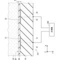
- FIG. 1 and 2 are respectively a front view and a rear view schematically showing the configuration of measurement system 500 having conductivity sensor 101 according to the present embodiment.
- FIG. 3 is a schematic partial cross-sectional view along line III-III of FIGS. 1 and 2;
- FIG. 4 is a schematic partial cross-sectional view along line IV-IV of FIGS. 1 and 2;
- FIG. 5 is a schematic partial cross-sectional view showing the manner in which the conductivity measurement method is being performed in the field of view of FIG.
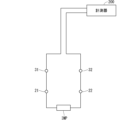
- FIG. 6 is a circuit diagram showing an approximate equivalent circuit corresponding to FIG.
- FIG. 7 is a schematic front view showing the configuration of the conductivity sensor 101 with the illustration of the protective layer 50 omitted.
- the liquid LQ whose conductivity is to be measured by the conductivity sensor 101 is indicated by a phantom line. Also shown in FIG. 5 is the liquid LQ.
- an XYZ orthogonal coordinate system is shown in each drawing to facilitate understanding of the directional relationship between the drawings. In this embodiment, the direction Z corresponds to the vertically upward direction.
- the measurement system 500 has a conductivity sensor 101 and a measuring instrument 200.
- the conductivity sensor 101 is a sensor for measuring the conductivity of the liquid LQ.
- Conductivity sensor 101 includes insulating layer 10 , first sensing electrode 21 , second sensing electrode 22 , and protective layer 50 .
- the conductivity sensor 101 may include a first pad electrode 31 , a second pad electrode 32 , a first via electrode 41 and a second via electrode 42 .
- Conductivity sensor 101 includes, as a schematic configuration, an insulating substrate in which electrodes including first detection electrode 21 and second detection electrode 22 are embedded.
- the insulating substrate is composed of the insulating layer 10 and the protective layer 50 .
- a first pad electrode 31 and a second pad electrode 32 are provided on the conductivity sensor 101 for electrical connection from outside the conductivity sensor 101 to the embedded electrodes.
- the insulating layer 10 is preferably made of a ceramic insulator, and more preferably made of the same material as the protective layer 50 .
- the thickness of the insulating layer 10 is, for example, about 1 mm.
- the first detection electrode 21 is provided on one surface of the insulating layer 10, as shown in FIGS.
- the second detection electrode 22 is provided on the one surface of the insulating layer 10 apart from the first detection electrode 21 .
- the minimum distance between the first detection electrode 21 and the second detection electrode 22 is preferably 30 ⁇ m or more and 2000 ⁇ m or less, more preferably 30 ⁇ m or more and 1000 ⁇ m or less.
- the first detection electrodes 21 and the second detection electrodes 22 are alternately positioned to form a line and space (L/S) pattern PT as shown in FIG. It can be.
- the line-and-space pattern PT has a length direction along the X direction and a width direction along the Z direction.
- the line length LL of the line-and-space pattern PT is preferably 1 mm or more and 20 mm or less.
- the line-and-space pattern PT includes at least one line L1 (for example, a plurality of lines L1 as shown in FIG. 7) that the first detection electrode 21 has and at least one line L1 that the second detection electrode 22 has.
- One line L2 (for example, a plurality of lines L2 as shown in FIG. 7) are alternately positioned.
- the minimum distance between line L1 and line L2, that is, the space width WS (also referred to as “S dimension”) of line-and-space pattern PT is preferably 30 ⁇ m or more and 2000 ⁇ m or less, more preferably 30 ⁇ m or more and 1000 ⁇ m or less.
- the width of each of the lines L1 and L2, that is, the line width WL (also referred to as "L dimension”) of the line and space pattern PT is preferably 30 ⁇ m or more and 2000 ⁇ m or less, more preferably 30 ⁇ m or more and 1000 ⁇ m or less. .
- the first detection electrode 21 and the second detection electrode 22 are preferably made of a refractory metal that is difficult to oxidize, such as platinum, tungsten or cobalt.
- the thickness of the first detection electrode 21 and the second detection electrode 22 is, for example, about 5 ⁇ m.
- the protective layer 50 covers the first detection electrodes 21 and the second detection electrodes 22 .
- the protective layer 50 has a surface SF and a surface facing the first sensing electrode 21 and the second sensing electrode 22 opposite the surface SF.
- the protective layer 50 has a thickness d, which preferably satisfies 1 ⁇ m ⁇ d ⁇ 10 ⁇ m, more preferably 1 ⁇ m ⁇ d ⁇ 5 ⁇ m.
- the protective layer 50 is made of an insulator. In particular, when the protective layer 50 is made of zirconia or alumina, the corrosion resistance and chemical resistance of the conductivity sensor 101 are enhanced.
- the protective layer 50 has a dielectric constant ⁇ , preferably satisfying ⁇ 10.
- ⁇ of about 30 can be obtained by using zirconia, and ⁇ of about 10 can be obtained by using alumina.
- ⁇ /d ⁇ 1 is satisfied.
- the protective layer 50 is preferably made of a sintered body, for example, from the viewpoint of manufacturing efficiency.
- the protective layer 50 shown in FIGS. 1 and 3 to 5 is one layer that continuously covers both the first detection electrode 21 and the second detection electrode 22, and has a particular pattern. not.
- the shape of the protective layer 50 can be simplified.
- the shape of the protective layer may alternatively have some pattern.
- the pattern may have first and second portions separated from each other, the first portion covering the first sensing electrode 21 and the second portion covering the second sensing electrode 22 . good. In this case, the first portion and the second portion of the protective layer 50 are separated by a region where the protective layer 50 is not provided.
- the first pad electrode 31 is provided on the surface of the insulating layer 10 opposite to the one surface.
- the second pad electrode 32 is provided separately from the first pad electrode 31 on the surface of the insulating layer 10 opposite to the one surface.
- the first via electrode 41 penetrates the insulating layer 10 and has one end connected to the first detection electrode 21 and the other end connected to the first pad electrode 31 .
- the second via electrode 42 penetrates the insulating layer 10 and has one end connected to the second detection electrode 22 and the other end connected to the second pad electrode 32 .
- the measuring instrument 200 has a function of measuring complex impedance and a function of extracting an extracted value from this complex impedance according to a predetermined extraction rule.
- the measuring instrument 200 may be a typical impedance analyzer, or may be a measuring instrument having a simpler configuration as long as the measuring method described later can be performed.
- the extraction rule the real part of the complex impedance is considered and the imaginary part of the complex impedance is ignored.
- the extraction rule may correspond to extracting the reciprocal of the resistive component, ie 1/R, from the complex impedance.
- the measuring instrument 200 is electrically connected to the first pad electrode 31 and the second pad electrode 32 .
- the complex impedance IMP is the complex impedance between the first detection electrode 21 and the second detection electrode 22 in the state shown in FIG. In the state shown in FIG. 5 , liquid LQ is in contact with protective layer 50 so as to face each of first detection electrode 21 and second detection electrode 22 through protective layer 50 .
- the complex impedance of the first pad electrode 31, the first detection electrode 21, and the first via electrode 41 therebetween, the second pad electrode 32, and the second detection electrode with respect to the complex impedance IMP 22 and the complex impedance of the second via electrode 42 therebetween is almost negligible.
- the complex impedance that the meter 200 will measure is substantially the complex impedance between the first sensing electrode 21 and the second sensing electrode 22, IMP (FIG. 6).
- a complex impedance generally has a resistance component (that is, R) and a reactance component.
- the reactance component is mainly formed by arranging the protective layer 50 and the liquid LQ in the electrical path between the first detection electrode 21 and the second detection electrode 22. is due to the capacitance value used. Therefore, hereinafter, the reactance component may be referred to as a capacitance value (that is, C).
- Table 1 below shows the simulation results of the detectable conductivity.
- the extraction rule “C” means that the capacitance value is extracted from the complex impedance as the extraction value
- the extraction rule “1/R” means that the extraction value is the resistance value from the complex impedance. It means that the reciprocal of the component is extracted. Therefore, the line of the extraction rule “C” corresponds to the comparative example, and the line of the extraction rule "1/R” corresponds to the present embodiment.
- detecttable conductivity is the slope of the extracted value with respect to the conductivity [unit: ⁇ S / cm] (in other words, the differential coefficient of the extracted value with respect to conductivity) is greater than or equal to the reference value. It is a range of conductivity such that When the extracted value is the admittance absolute value [unit: S] or the reciprocal of the resistance component [unit: S], the reference values are 10 ⁇ 10 and 10 ⁇ 9 at frequencies of 1 kHz, 10 kHz, 100 kHz and 1000 kHz, respectively. , 10 ⁇ 8 , 10 ⁇ 7 [unit: S/( ⁇ S/cm)].
- the reference value is 10 ⁇ 14 [unit: F/( ⁇ S/cm)] at frequencies of 1 kHz, 10 kHz, 100 kHz and 1000 kHz.
- the reason why the "detectable conductivity" depends on the frequency as described above when the extracted value is the admittance absolute value [unit: S] or the reciprocal of the resistance component [unit: S] is because The reason is that the reference value can be determined rationally in consideration of the large frequency dependence of the measurement variation.
- the symbol "-" indicates that no detectable conductivity range was found in the simulation range. For example, the larger the dimension L or the measurement frequency, the smaller the change in the extracted value with respect to the change in conductivity. It becomes difficult to calculate the rate.
- a pair of values described as "L/S” indicates a set of line width WL and space width WS in line and space pattern PT.
- each of the line width WL and the space width WS is 50 ⁇ m in Table 1 above, it is not limited to this. Also, although the line width WL and the space width WS are the same in Table 1 above, they may be different from each other.
- Table 2 below shows simulation results for systematically varied parameters for minimum and maximum detectable conductivity when the extraction rule "1/R" is used.
- the space width WS (dimension S) of the line-and-space pattern PT is preferably 200 ⁇ m or less, more preferably 100 ⁇ m or less. This makes it easier to ensure the detectable conductivity range down to lower values.
- the space width WS is preferably 30 ⁇ m or more, more preferably 50 ⁇ m or more.
- the maximum detectable conductivity decreases as the space width WS increases.
- the reason for this phenomenon is thought to be that the electrode area per unit area decreases due to the increase in the space width WS.
- the line width WL (dimension L) of the line and space pattern PT (FIG. 7) is preferably 500 ⁇ m or more, more preferably 1000 ⁇ m or more. This makes it easier to secure a detectable conductivity range up to a higher value. Also, from the viewpoint of miniaturization of the detection electrode, the line width WL is preferably 2000 ⁇ m or less, more preferably 1000 ⁇ m or less.
- a phenomenon in which the maximum detectable conductivity decreases with an increase in the line width WL is also seen in some of the results in Table 2. Specifically, this phenomenon is observed when the line width WL is increased from 1000 ⁇ m to 2000 ⁇ m in the measurement at 100 kHz, and when the line width WL is increased from 500 ⁇ m to 1000 ⁇ m in the measurement at 1000 kHz. The reason for this phenomenon is that due to the increase in the line width WL, the conductivity range with relatively high detection sensitivity shifts to higher conductivities, while the change in the extracted value is generally gradual. It is from. From this point of view, the line width WL may be 1000 ⁇ m or less.
- the maximum value of detectable conductivity can be increased by using a somewhat high frequency, using an excessively high frequency rather decreases it. This is because the relatively sensitive conductivity range shifts to higher conductivities due to the increase in measurement frequency, while the change in the extracted value is generally gradual. In this regard, it is often preferred that the measurement frequency be 100 kHz or less.
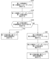
- FIG. 8 is a schematic flow diagram of a conductivity measuring method for measuring the conductivity of the liquid LQ using the conductivity sensor 101.
- step S101 the first complex impedance between the first detection electrode 21 and the second detection electrode 22 at the first frequency is measured in the state of FIG.
- the liquid LQ is in contact with the protective layer 50 so as to face each of the first detection electrode 21 and the second detection electrode 22 through the protective layer 50, as described above.
- This measurement may be performed by a complex impedance measuring section (not shown) included in the measuring instrument 200 .
- the complex impedance measuring section has a function of measuring complex impedance at a first frequency and a second frequency which will be described later.
- the function of measuring the complex impedance is, in other words, the function of applying an AC signal of the above frequency to the object to be measured and measuring the ratio and phase difference between the voltage and current of the AC signal.
- a first extraction value is extracted from the first complex impedance according to a predetermined extraction rule. This extraction may be performed by an extraction unit (not shown) of the measuring instrument 200 .
- the extracted first extraction value may be stored in a storage unit (not shown) of measuring instrument 200 .
- step S200 it is determined whether or not the first extraction value is within a predetermined allowable range. This determination may be made by a determining section (not shown) of the measuring instrument 200 .
- the tolerance range may be determined by pre-examining a range in which the extraction value is sufficiently sensitive to the conductivity of the liquid LQ.
- the provisional conductivity of the liquid LQ determined from the first extraction value may be used in the determination process of step S200. In that case, the aforementioned detectable conductivity range may be used as the acceptable range. In other words, the determination process may be performed depending on whether the provisional conductivity is within the detectable conductivity range. Even then, a definitive (rather than tentative) conductivity is determined in the steps below.
- step S303 the conductivity of the liquid LQ is determined based on the first extracted value. This determination may be made based on previously examined correspondences between extracted values and conductivity. This correspondence relationship may be determined experimentally, for example. This decision may be made by a decision unit (not shown) of the measuring instrument 200 .
- step S200 If it is determined in step S200 that the first extraction value is out of the allowable range, in steps S401 to S403, the first detection electrode 21 and the second detection electrode 21 at the second frequency in the state shown in FIG.
- the electrical conductivity of the liquid LQ is determined based on the second extracted value extracted from the second complex impedance between the detection electrode 22 and according to the above extraction rule.
- the second frequency is different than the first frequency.
- step S401 in the state of FIG. 5, the second complex impedance between the first detection electrode 21 and the second detection electrode 22 at the second frequency is measured. be.
- the second complex impedance is measured only when it is determined in step S200 that the first extracted value is outside the allowable range. Therefore, in the present embodiment, in measuring instrument 200, the determination section causes the complex impedance measurement section to start measurement in step S401.
- a second extraction value is extracted from the second complex impedance according to the extraction rule. This extraction may be performed by the above-described extraction section of the measuring instrument 200 .
- the conductivity of the liquid LQ is determined based on the second extracted value. This extraction may be performed by the determining unit of the measuring instrument 200 .
- the storage unit, determination unit, and determination unit described above may be implemented by a control device (not shown).
- the control device may consist of a general computer having electric circuits.
- a typical computer consists of a central processing unit (i.e. CPU), read only memory (i.e. ROM), random access memory (i.e. RAM), storage, input It has a display unit, a display unit, a communication unit, and a bus line interconnecting them.
- a method using two frequencies, the first frequency and the second frequency has been described, but as a first modification, more than two frequencies may be used as appropriate. .
- only one frequency may be used. Specifically, in the flowchart of FIG. 8, step S200 and steps S401 to S403 may be omitted. In this case, after step S102, step S303 is performed without going through step S200.
- the AC signal that can be applied to the measurement object by the complex impedance measuring unit may be limited to only one frequency accordingly. .
- the second frequency is It may be higher than the first frequency. Also, if the first extracted value is smaller than the allowable range in step S200, the second frequency may be lower than the first frequency in step S401.
- the second frequency is the first frequency in step S401.
- the first extracted value is greater than the allowable range in step S200
- the second frequency is the first frequency in step S401.
- the first extracted value is smaller than the allowable range in step S200
- the second frequency may be higher than the first frequency in step S401. Since the simulation results when the reciprocal of the resistance component is used as the extracted value have already been shown in Table 1 above, description of the simulation results when the resistance component is used as the extracted value is omitted.
- FIG. 9 is a partial cross-sectional view schematically showing one step in the method of manufacturing conductivity sensor 101 according to the present embodiment.
- a green sheet 10G serving as insulating layer 10
- a paste layer 21G serving as first sensing electrode 21, a paste layer 22G serving as second sensing electrode 22, and a first pad. It includes a paste layer 31G that becomes the electrode 31, a paste layer 32G that becomes the second pad electrode 32, a paste layer 41G that becomes the first via electrode 41, and a paste layer 42G that becomes the second via electrode 42.
- a laminate is prepared.
- Each paste layer can be formed by printing a paste containing metal powder and ceramic powder on the green sheet 10G.
- the green sheet 10G may be composed of a single layer, or may be composed of a plurality of laminated green sheets.
- a green sheet 50G to be the protective layer 50 is crimped onto the laminate as indicated by an arrow (FIG. 9). This crimping is preferably performed with heating.
- the protective layer 50 is made of a sintered body.
- the extraction rule used in step S102 considers the real part of the complex impedance and ignores the imaginary part of the complex impedance. This helps ensure sufficient sensitivity of the extracted value to the conductivity of the liquid LQ, even in the high conductivity region. Therefore, it is possible to measure the conductivity of the liquid LQ with sufficient sensitivity over a wide conductivity range.
- step S303 the liquid LQ is determined based on the first extracted value. If the conductivity is determined and step S200 determines that the first extracted value is outside the acceptable range, steps S401-S403 perform a second extraction from the second complex impedance at a second frequency. Based on the value the conductivity of the liquid LQ is determined. This ensures sufficient sensitivity of the extracted value to the conductivity of the liquid LQ over a wider conductivity range. Therefore, the conductivity measurement of the liquid LQ with sufficient sensitivity can be performed over a wider conductivity range.
- step S401 is performed only when it is determined in step S200 that the first extracted value is outside the allowable range. This makes it possible to omit the execution of step S401 when it is unnecessary.
- the line length LL (FIG. 7) of the line-and-space pattern PT is preferably 1 mm or more and 20 mm or less.
- the sensitivity of the conductivity sensor 101 can be enhanced by setting the line length LL to 1 mm or more.
- By setting the line length LL to 20 mm or less it is possible to suppress the probability of defects caused by foreign matter adhering to the line and space pattern PT. Further, since the line length LL is 20 mm or less, it is possible to avoid the size of the conductivity sensor 101 from becoming excessively large.
- the space width WS is preferably 30 ⁇ m or more and 2000 ⁇ m or less, more preferably 30 ⁇ m or more and 1000 ⁇ m or less. Since the space width WS is 30 ⁇ m or more, the space width WS can be easily controlled by general laminated ceramic technology. When the space width WS is 2000 ⁇ m or less (more preferably 1000 ⁇ m or less), it is possible to avoid excessive electrical coupling between the first detection electrode 21 and the second detection electrode 22 via the liquid LQ. Therefore, it becomes easy to avoid that the sensitivity of the conductivity sensor 101 becomes too small.
- the protective layer 50 When the protective layer 50 is made of zirconia or alumina and has a thickness d of 1 ⁇ m or more and 10 ⁇ m or less, ⁇ /d of the protective layer 50 becomes large. It is easy to sufficiently secure electrical coupling between each of the electrodes 22 and the liquid LQ. Thereby, the sensor sensitivity can be increased.
- the material of the protective layer 50 preferably has a high dielectric constant ⁇ . From this point of view, zirconia or alumina is preferable, and zirconia is more preferable.
- alumina is preferable to zirconia as the material of the protective layer 50 in order to suppress the temperature dependence of the conductivity sensor 101 . Alumina is more preferable than zirconia as a material for the protective layer 50 from the viewpoint of heat resistance of the conductivity sensor 101 as well.
- the protective layer 50 may be made of a sintered body. As a result, in manufacturing the conductivity sensor, it is possible to avoid a decrease in manufacturing efficiency due to the formation of the protective layer made of a non-sintered body. Moreover, since the protective layer 50 and the insulating layer 10 are a sintered body as an integral structure, defects originating from the interface between them are less likely to occur. Therefore, properties such as chemical resistance and thermal shock are improved.
- Both the insulating layer 10 and the protective layer 50 are preferably made of a ceramic insulator, and more preferably made of the same material. This suppresses the difference in shrinkage rate in the firing process for manufacturing the conductivity sensor 101 . Therefore, even if the thickness d of the protective layer 50 is relatively small, the protective layer 50 without pinholes can be obtained. Therefore, the thickness d can be reduced while sufficiently obtaining the effect of improving the corrosion resistance and chemical resistance of the protective layer 50 .
- the portion that will become the protective layer 50 is preferably formed by pressing the green sheet 50G (FIG. 9). As a result, even if the thickness d of the protective layer 50 is relatively small, the protective layer 50 without pinholes can be obtained as compared with the case where the portion is formed by applying ceramic paste.
- the first detection electrode 21 and the second detection electrode 22 are preferably made of a high melting point metal, such as platinum, tungsten or cobalt. As a result, volatilization and melting of the electrodes in the baking process for manufacturing the conductivity sensor 101 can be avoided.
- the simulation results at frequencies of 1 kHz, 10 kHz, 100 kHz, and 1000 kHz shown in the present embodiment are expected to roughly reflect the characteristics of the 1 kHz order, 10 kHz order, 100 kHz order, and 1000 kHz order, respectively.
- the characteristics at frequencies of 1 kHz ⁇ 10%, 10 kHz ⁇ 10%, 100 kHz ⁇ 10%, and 1000 kHz ⁇ 10% are It is believed to be approximately the same as the properties disclosed above.
- the "100 kHz order" is, in other words, a frequency between the frequency of the order of 10 kHz, which is one digit lower, and the frequency of the order of 1000 kHz, which is one digit higher. frequency). The same is true for other frequency orders.
- the characteristics in dimension L and dimension S are considered to be approximately the same as the characteristics in dimension L ⁇ 10% and dimension S ⁇ 10%.
- Embodiment 2 describes another method for measuring the conductivity of liquid LQ using a measurement system substantially similar to measurement system 500 described in Embodiment 1 above.
- FIG. 10 is a schematic flow chart of the conductivity measuring method in this embodiment. Steps S101 and S102 are performed in the same manner as in the conductivity measuring method (FIG. 8) of the first embodiment.
- steps S401 and S402 are performed before step S200. Therefore, in the second embodiment, unlike the first embodiment, in the measuring instrument 200, the complex impedance measurement section starts the measurement in step S401 without depending on the determination section.
- step S200 similarly to the first embodiment, it is determined whether the first extraction value is within a predetermined allowable range. If it is determined in step S200 that the first extracted value is within the allowable range, the conductivity of liquid LQ is determined based on the first extracted value in step S303, as in the first embodiment. be. If it is determined in step S200 that the first extracted value is outside the allowable range, then in step S403 the conductivity of the liquid LQ is determined based on the second extracted value.
- the second complex impedance need not be measured after step S200, as it has already been measured before step S200.
- step S200 is preceded by the measurement of the complex impedance at each of the more than two frequencies and the extraction of the extracted values. It is then determined on which of these multiple extracted values the electrical conductivity of the liquid LQ should be determined. This allows the optimum of more than two frequencies to be used to determine the conductivity of the liquid LQ.
- Reference Signs List 10 insulating layer 21: first detection electrode 22: second detection electrode 31: first pad electrode 32: second pad electrode 41: first via electrode 42: second via electrode 50: protective layer 101: conductivity sensor 200: measuring instrument 500: measurement system PT: line and space pattern
Landscapes
- Chemical & Material Sciences (AREA)
- Physics & Mathematics (AREA)
- General Physics & Mathematics (AREA)
- Life Sciences & Earth Sciences (AREA)
- Electrochemistry (AREA)
- Health & Medical Sciences (AREA)
- Chemical Kinetics & Catalysis (AREA)
- Analytical Chemistry (AREA)
- Biochemistry (AREA)
- General Health & Medical Sciences (AREA)
- Immunology (AREA)
- Pathology (AREA)
- Investigating Or Analyzing Materials By The Use Of Electric Means (AREA)
Abstract
液体の導電率を測定する導電率測定方法は、a)保護層(50)を介して第1の検出電極(21)および第2の検出電極(22)の各々に面するように液体(LQ)が前記保護層(50)に接触した状態における、第1の周波数での前記第1の検出電極(21)と前記第2の検出電極(22)との間の第1の複素インピーダンスを測定する工程と、b)予め定められた抽出規則に従って、前記第1の複素インピーダンスから第1の抽出値を抽出する工程と、c)前記第1の抽出値に基づいて前記液体(LQ)の導電率を決定する工程と、を備える。前記抽出規則において、複素インピーダンスの実数部は考慮され、かつ、複素インピーダンスの虚数部は無視される。
Description
本発明は、導電率測定方法に関するものであり、特に、導電率センサを用いて液体の導電率を測定する方法に関するものである。
国際公開第2021/241628号(特許文献1)は静電容量式センサを開示している。この静電容量式センサは、絶縁層と、第1の検出電極と、第2の検出電極と、保護層と、を含む。前記第1の検出電極は、前記絶縁層上に設けられている。前記第2の検出電極は、前記絶縁層上に前記第1の検出電極から離れて設けられており、前記第1の検出電極と共に前記静電容量を形成している。前記保護層は、前記第1の検出電極および前記第2の検出電極を覆っており、1μm≦d≦10μmを満たす厚みdを有しており、ジルコニアまたはアルミナからなる。
特開2019-109224号公報(特許文献2)は、計測領域が小さい場合でも、液体の広い導電率のレンジを計測可能とすることが意図された、小型の導電率センサを開示している。前記導電率センサは、それぞれの電極が前記センサのセル定数を決定する表面積を有する第1電極および第2電極を含む。少なくとも一の前記電極には、それぞれの電極の表面積が変更可能でありそれにより前記センサの前記セル定数を変化させるように配置されたスイッチング手段が備えられている。例えば、前記第1電極および前記第2電極は複数のフィンガー電極を含む。
上記特許文献1のような構成を有する静電容量式センサを用いて、十分な感度での液体の導電率測定を広い導電率範囲にわたって行う方法は、これまで十分に検討されていなかった。例えば、上記特許文献2の技術も、特許文献1で開示されているような保護層を形成することは想定していないと考えられる。なぜならば、保護層の形成は電極と液体との間のキャパシタンスの形成につながるところ、特許文献2によれば、電極と液体との界面のキャパシタンスの影響によって電極のインピーダンスが高くなることが、液体の導電率の計測レンジを広く確保する上で問題視されているからである。さらに、上記特許文献2は、電極と液体との化学的相互作用を避ける手段として、電極材料を不活性の導電性材料とすることのみしか開示しておらず、当該手段として保護層を適用することについては言及されていない。この理由は、引用文献2の技術においては、インピーダンスの増大につながる保護層の付加が想定されていないからであると考えられる。
本発明は以上のような課題を解決するためになされたものであり、その目的は、十分な感度での液体の導電率測定を、広い導電率範囲にわたって行うことができる導電率測定方法を提供することである。
第1の態様は、絶縁層と、前記絶縁層上に設けられた第1の検出電極と、前記絶縁層上に前記第1の検出電極から離れて設けられた第2の検出電極と、前記第1の検出電極および前記第2の検出電極を覆い絶縁体からなる保護層と、を備える導電率センサを用いて液体の導電率を測定する導電率測定方法であって、
a)前記保護層を介して前記第1の検出電極および前記第2の検出電極の各々に面するように前記液体が前記保護層に接触した状態における、第1の周波数での前記第1の検出電極と前記第2の検出電極との間の第1の複素インピーダンスを測定する工程と、
b)予め定められた抽出規則に従って、前記第1の複素インピーダンスから第1の抽出値を抽出する工程と、
c)前記第1の抽出値に基づいて前記液体の導電率を決定する工程と、
を備える。前記抽出規則において、複素インピーダンスの実数部は考慮され、かつ、複素インピーダンスの虚数部は無視される。
a)前記保護層を介して前記第1の検出電極および前記第2の検出電極の各々に面するように前記液体が前記保護層に接触した状態における、第1の周波数での前記第1の検出電極と前記第2の検出電極との間の第1の複素インピーダンスを測定する工程と、
b)予め定められた抽出規則に従って、前記第1の複素インピーダンスから第1の抽出値を抽出する工程と、
c)前記第1の抽出値に基づいて前記液体の導電率を決定する工程と、
を備える。前記抽出規則において、複素インピーダンスの実数部は考慮され、かつ、複素インピーダンスの虚数部は無視される。
第2の態様は、第1の態様の導電率測定方法であって、
前記導電率測定方法は、
d)前記c)の前に、前記第1の抽出値が、予め定められた許容範囲内にあるか否か、を判定する工程と、
e)前記d)において前記第1の抽出値が前記許容範囲外にあると判定された場合、前記保護層を介して前記第1の検出電極および前記第2の検出電極の各々に面するように前記液体が前記保護層に接触した状態における、前記第1の周波数とは異なる第2の周波数での前記第1の検出電極と前記第2の検出電極との間の第2の複素インピーダンスから前記抽出規則に従って抽出された第2の抽出値に基づいて前記液体の導電率を決定する工程と、
をさらに備え、
前記c)は、前記d)において前記第1の抽出値が前記許容範囲内にあると判定された場合に行われる。
第3の態様は、第2の態様の導電率測定方法であって、前記e)は、
e1)前記d)において前記第1の抽出値が前記許容範囲外にあると判定された場合にのみ、前記第2の複素インピーダンスを測定する工程
を含む。
e1)前記d)において前記第1の抽出値が前記許容範囲外にあると判定された場合にのみ、前記第2の複素インピーダンスを測定する工程
を含む。
第4の態様は、第2の態様の導電率測定方法であって、
f)前記d)よりも前に、前記第2の複素インピーダンスを測定する工程
をさらに備える。
f)前記d)よりも前に、前記第2の複素インピーダンスを測定する工程
をさらに備える。
第5の態様は、第1から第4の態様のいずれかひとつの導電率測定方法であって、前記抽出規則は、複素インピーダンスから抵抗成分の逆数を抽出することに相当する。
第6の態様は、第2から第4の態様のいずれかひとつの導電率測定方法であって、前記抽出規則は、複素インピーダンスから抵抗成分の逆数を抽出することに相当し、前記d)において前記第1の抽出値が前記許容範囲よりも大きい場合、前記e)において前記第2の周波数は前記第1の周波数よりも高くされる。
第7の態様は、第2から第4および第6の態様のいずれかひとつの導電率測定方法であって、前記抽出規則は、複素インピーダンスから抵抗成分の逆数を抽出することに相当し、前記c)において前記第1の抽出値が前記許容範囲よりも小さい場合、前記e)において前記第2の周波数は前記第1の周波数よりも低くされる。
第8の態様は、第1から第7の態様のいずれかひとつの導電率測定方法であって、前記保護層は、ジルコニアまたはアルミナからなり、1μm以上10μm以下の厚みを有している。
第9の態様は、第1から第8の態様のいずれかひとつの導電率測定方法であって、前記保護層は焼結体からなる。
第10の態様は、第1から第9の態様のいずれかひとつの導電率測定方法であって、前記導電率センサにおいて、前記第1の検出電極と前記第2の検出電極とが交互に位置することによって、ライン幅およびスペース幅を有するラインアンドスペースパターンが構成されており、スペース幅は200μm以下である。
第11態様は、第1から第9の態様のいずれかひとつの導電率測定方法であって、前記導電率センサにおいて、前記第1の検出電極と前記第2の検出電極とが交互に位置することによって、ライン幅およびスペース幅を有するラインアンドスペースパターンが構成されており、ライン幅は500μm以上である。
第12態様は、第1から第9の態様のいずれかひとつの導電率測定方法であって、前記導電率センサにおいて、前記第1の検出電極と前記第2の検出電極とが交互に位置することによって、ライン幅およびスペース幅を有するラインアンドスペースパターンが構成されており、スペース幅は200μm以下であり、かつライン幅は500μm以上である。
一実施の形態によれば、抽出規則において、複素インピーダンスの実数部は考慮され、かつ、複素インピーダンスの虚数部は無視される。これにより、液体の導電率に対しての抽出値の十分な感受性を、高い導電率域でも確保しやすくなる。よって、十分な感度での液体の導電率測定を、広い導電率範囲にわたって行うことができる。
前記導電率測定方法は、d)前記c)の前に、前記第1の抽出値が、予め定められた許容範囲内にあるか否か、を判定する工程と、e)前記d)において前記第1の抽出値が前記許容範囲外にあると判定された場合、前記保護層を介して前記第1の検出電極および前記第2の検出電極の各々に面するように前記液体が前記保護層に接触した状態における、前記第1の周波数とは異なる第2の周波数での前記第1の検出電極と前記第2の検出電極との間の第2の複素インピーダンスから前記抽出規則に従って抽出された第2の抽出値に基づいて前記液体の導電率を決定する工程と、をさらに備えてよい。前記c)は、前記d)において前記第1の抽出値が前記許容範囲内にあると判定された場合に行われる。
なお前記抽出規則は、複素インピーダンスから抵抗成分の逆数を抽出することに相当してよい。この場合において、前記d)において前記第1の抽出値が前記許容範囲よりも大きい場合、前記e)において前記第2の周波数は前記第1の周波数よりも高くてよい。また、前記d)において前記第1の抽出値が前記許容範囲よりも小さい場合、前記e)において前記第2の周波数は前記第1の周波数よりも低くてよい。
上記方法によれば、第1の周波数での第1の検出電極と第2の検出電極との間の第1の複素インピーダンスからの第1の抽出値が許容範囲内にあると判定された場合は第1の抽出値に基づいて液体の導電率が決定され、第1の周波数での第1の検出電極と第2の検出電極との間の第1の複素インピーダンスからの第1の抽出値が許容範囲外にあると判定された場合は、第2の周波数での第2の複素インピーダンスからの第2の抽出値に基づいて液体の導電率が決定される。これにより、液体の導電率に対しての抽出値の十分な感受性を、より広い導電率範囲にわたって確保することができる。よって、十分な感度での液体の導電率測定を、より広い導電率範囲にわたって行うことができる。
前記e)は、e1)前記d)において前記第1の抽出値が前記許容範囲外にあると判定された場合にのみ、前記第2の複素インピーダンスを測定する工程、を含んでよい。これにより、第2の複素インピーダンスの測定が不必要なときにそれを省略することができる。
前記導電率測定方法は、f)前記d)よりも前に、前記第2の複素インピーダンスを測定する工程、をさらに備えてよい。これにより、第2の複素インピーダンスを前記d)の後に測定する必要がない。
前記保護層は、ジルコニアまたはアルミナからなり、1μm以上10μm以下の厚みを有していてよい。その場合、第1の検出電極および第2の検出電極のそれぞれと液体との間で保護層が形成する静電容量が第1の検出電極と前記第2の検出電極との間のインピーダンスの測定に及ぼす影響が大きいところ、上記実施の形態によれば、この影響下においても、十分な感度での液体の導電率測定を、広い導電率範囲にわたって行うことができる。
前記保護層は焼結体からなっていてよい。これにより、導電率センサの製造において、非焼結体からなる保護層を形成することに起因して製造効率が低下することが避けられる。また、保護層および絶縁層が、一体の構造体としての焼結体であるので、これらの間の界面を起点とする不良が発生しにくくなる。よって、耐薬品性および耐熱衝撃などの特性が改善する。
前記導電率センサにおいて、前記第1の検出電極と前記第2の検出電極とが交互に位置することによって、ライン幅およびスペース幅を有するラインアンドスペースパターンが構成されていてよく、スペース幅は200μm以下であってよい。これにより、検出可能な導電率の範囲を、より低い値まで確保しやすくなる。
前記導電率センサにおいて、前記第1の検出電極と前記第2の検出電極とが交互に位置することによって、ライン幅およびスペース幅を有するラインアンドスペースパターンが構成されていてよく、ライン幅は500μm以上であってよい。これにより、検出可能な導電率の範囲を、より高い値まで確保しやすくなる。
前記導電率センサにおいて、前記第1の検出電極と前記第2の検出電極とが交互に位置することによって、ライン幅およびスペース幅を有するラインアンドスペースパターンが構成されていてよく、スペース幅は200μm以下であってよく、かつライン幅は500μm以上であってよい。これにより、検出可能な導電率の範囲を、より低い値から、より高い値まで、広く確保しやすくなる。
この発明の目的、特徴、態様、および利点は、以下の詳細な説明と添付図面とによって、より明白となる。
以下、図面に基づいて本発明の実施の形態について説明する。
<実施の形態1>
(構成)
図1および図2のそれぞれは、本実施の形態における導電率センサ101を有する測定システム500の構成を概略的に示す正面図および背面図である。図3は、図1および図2の線III-IIIに沿う概略的な部分断面図である。図4は、図1および図2の線IV-IVに沿う概略的な部分断面図である。図5は、図4の視野での導電率測定方法の実施中の様子を示す概略的な部分断面図である。図6は、図5に対応する近似的な等価回路を示す回路図である。図7は、導電率センサ101の構成を、保護層50の図示を省略して示す、概略的な正面図である。なお、図1および図2においては、導電率センサ101によって導電率を測定されることになる液体LQが仮想線によって示されている。また図5においては液体LQが示されている。また、図面間の方向関係を理解しやすくするために、各図へXYZ直交座標系が示されている。本実施の形態においては方向Zが鉛直上方に対応している。
測定システム500は、導電率センサ101と、計測器200とを有している。導電率センサ101は、液体LQの導電率を測定するためのセンサである。導電率センサ101は、絶縁層10と、第1の検出電極21と、第2の検出電極22と、保護層50とを含む。さらに、導電率センサ101は、第1のパッド電極31と、第2のパッド電極32と、第1のビア電極41と、第2のビア電極42とを含んでいてよい。導電率センサ101は、概略的な構成として、第1の検出電極21および第2の検出電極22を含む電極が埋設された絶縁基体を含む。当該絶縁基体は絶縁層10および保護層50によって構成されている。埋設された電極への、導電率センサ101の外部からの電気的接続のために、第1のパッド電極31および第2のパッド電極32が導電率センサ101に設けられている。
絶縁層10は、セラミック絶縁体からなることが好ましく、保護層50と同じ材料からなることがより好ましい。絶縁層10の厚みは、例えば1mm程度である。
第1の検出電極21は、図3~図5に示されているように、絶縁層10の一の面上に設けられている。第2の検出電極22は、絶縁層10の当該一の面上に第1の検出電極21から離れて設けられている。第1の検出電極21と第2の検出電極22との間の最小間隔は、好ましくは30μm以上2000μm以下であり、より好ましくは30μm以上1000μm以下である。
導電率センサ101において、第1の検出電極21と第2の検出電極22とが交互に位置することによって、図7に示されているように、ラインアンドスペース(L/S)パターンPTが構成されていてよい。図7に示された例においては、ラインアンドスペースパターンPTは、X方向に沿った長さ方向と、Z方向に沿った幅方向とを有している。ラインアンドスペースパターンPTのライン長LLは、1mm以上20mm以下が好ましい。またラインアンドスペースパターンPTは、第1の検出電極21が有する少なくとも1つのラインL1(例えば、図7に示されているように、複数のラインL1)と、第2の検出電極22が有する少なくとも1つのラインL2(例えば、図7に示されているように、複数のラインL2)とが交互に位置することによって構成されている。ラインL1とラインL2との最小間隔、すなわちラインアンドスペースパターンPTのスペース幅WS(「S寸法」とも称する)は、好ましくは30μm以上2000μm以下であり、より好ましくは30μm以上1000μm以下である。またラインL1とラインL2との各々の幅、すなわちラインアンドスペースパターンPTのライン幅WL(「L寸法」とも称する)は、好ましくは30μm以上2000μm以下であり、より好ましくは30μm以上1000μm以下である。
第1の検出電極21および第2の検出電極22は、酸化しにくい高融点金属からなることが好ましく、例えば、白金、タングステンまたはコバルトからなる。第1の検出電極21および第2の検出電極22の厚みは、例えば5μm程度である。
保護層50は、第1の検出電極21および第2の検出電極22を覆っている。具体的には、保護層50は、表面SFと、表面SFと反対の、第1の検出電極21および第2の検出電極22に面する面と、を有している。保護層50は厚みdを有しており、厚みdは、好ましくは1μm≦d≦10μmを満たし、より好ましくは、1μm≦d≦5μmを満たす。保護層50は、絶縁体からなる。特に、保護層50がジルコニアまたはアルミナからなる場合、導電率センサ101の耐食性および耐薬品性が高められる。保護層50は比誘電率εを有しており、好ましくは、ε≧10が満たされている。例えば、ジルコニアを用いることによって30程度のεを得ることができ、また、アルミナを用いることによって10程度のεを得ることができる。好ましくは、ε/d≧1が満たされている。保護層50は、例えば製造効率の観点で、焼結体からなることが好ましい。
なお図1および図3~図5に示された保護層50は、第1の検出電極21と第2の検出電極22との両方を連続的に覆う1つの層であり、特段のパターンを有していない。この場合、保護層50の形状を簡素なものとすることができる。一方で、保護層の形状が、より複雑なものであることが許容される場合は、変形例として、保護層が何らかのパターンを有してよい。このパターンは、互いに離れた第1および第2の部分を有していてよく、第1の部分が第1の検出電極21を覆い、かつ第2の部分が第2の検出電極22を覆ってよい。この場合、保護層50の第1の部分と第2の部分との間は、保護層50が設けられない領域によって隔てられる。
第1のパッド電極31は、絶縁層10の、上記一の面と反対の面上に設けられている。第2のパッド電極32は、絶縁層10の、上記一の面と反対の面上に、第1のパッド電極31から離れて設けられている。第1のビア電極41は、絶縁層10を貫通しており、第1の検出電極21につながれた一方端と、第1のパッド電極31につながれた他方端とを有している。第2のビア電極42は、絶縁層10を貫通しており、第2の検出電極22につながれた一方端と、第2のパッド電極32につながれた他方端とを有している。
計測器200は、複素インピーダンスを測定する機能と、予め定められた抽出規則に従ってこの複素インピーダンスから抽出値を抽出する機能とを有している。計測器200は、典型的なインピーダンスアナライザであってもよいが、後述の測定方法が実施可能な範囲でより簡素化された構成を有する計測器であってもよい。前記抽出規則において、複素インピーダンスの実数部は考慮され、かつ、複素インピーダンスの虚数部は無視される。抽出規則は、複素インピーダンスから抵抗成分の逆数、すなわち1/R、を抽出することに相当してよい。
計測器200は、第1のパッド電極31および第2のパッド電極32に電気的に接続されている。ここで、図6の等価回路を参照して、複素インピーダンスIMPは、図5に示された状態における、第1の検出電極21と第2の検出電極22との間の複素インピーダンスである。図5に示された状態においては、保護層50を介して第1の検出電極21および第2の検出電極22の各々に面するように液体LQが保護層50に接触している。複素インピーダンスIMPに対しての、第1のパッド電極31、第1の検出電極21およびそれらの間の第1のビア電極41が有する複素インピーダンスと、第2のパッド電極32、第2の検出電極22およびそれらの間の第2のビア電極42が有する複素インピーダンスと、による影響は、ほとんど無視できる。よって、計測器200が測定することになる複素インピーダンスは、実質的に、第1の検出電極21と第2の検出電極22との間の複素インピーダンスでIMP(図6)ある。
複素インピーダンスは、一般に、抵抗成分(すなわちR)とリアクタンス成分とを有している。本実施の形態の構成においては、リアクタンス成分は主に、第1の検出電極21と第2の検出電極22との間の電気的経路に保護層50および液体LQが配置されていることによって形成される静電容量値に起因している。よって、以下において、リアクタンス成分を静電容量値(すなわちC)と称することがある。
以下の表1に、検出可能導電率のシミュレーション結果について示す。

なお上記表1において、抽出規則「C」は、抽出値として複素インピーダンスから静電容量値が抽出されることを意味しており、抽出規則「1/R」は、抽出値として複素インピーダンスから抵抗成分の逆数が抽出されることを意味している。よって、抽出規則「C」の行は比較例に対応し、抽出規則「1/R」の行は本実施の形態に対応する。
また「検出可能導電率」として示されているのは、導電率[単位:μS/cm]に対しての抽出値の傾き(言い換えれば、導電率に関しての抽出値の微分係数)が基準値以上となるような導電率の範囲である。抽出値が、アドミタンス絶対値[単位:S]、または抵抗成分の逆数[単位:S]である場合、周波数1kHz、10kHz、100kHz、1000kHzのそれぞれで、基準値は、10-10、10-9、10-8、10-7[単位:S/(μS/cm)]である。また、抽出値が静電容量値[単位:F]である場合、周波数1kHz、10kHz、100kHz、1000kHzの各々で、基準値は10-14[単位:F/(μS/cm)]である。なお、抽出値がアドミタンス絶対値[単位:S]または抵抗成分の逆数[単位:S]である場合に「検出可能導電率」が上記のように周波数に依存している理由は、当該場合においては、測定ばらつきの周波数依存性が大きいことから、これを勘案して基準値が合理的に定められるようにするためである。後述の表2において、記号「-」は、検出可能な導電率範囲がシミュレーション範囲において見出されないことを示す。例えば、寸法Lまたは測定周波数が大きくなるほど、導電率の変化に対する上記抽出値の変化が小さくなる傾向があり、当該傾向が過度に進むと、導電率の検出、言い換えれば、十分な精度での導電率の算出、が困難となる。
また、「L/S」として記載されている1対の値は、ラインアンドスペースパターンPTにおけるライン幅WLとスペース幅WSとの組を示している。なおライン幅WLおよびスペース幅WSの各々は、上記表1においては50μmであるが、これに限定されるものではない。また上記表1においてはライン幅WLとスペース幅WSとが同じであるが、これらは互いに異なってもよい。以下の表2に、抽出規則「1/R」が用いられる場合における、検出可能導電率の最小および最大についての、体系的にパラメータが変化させられた場合のシミュレーション結果を示す。

上記表1の結果においては、周波数が高いほど、検出可能導電率は、より高い導電率域へシフトする傾向がある。また、同じ周波数で比較されたとき、抽出規則「C」に比して抽出規則「1/R」の方が、検出可能導電率の比率「最大/最小」が顕著に高い。よって、抽出規則として、複素インピーダンスの虚数部に対応する「C」ではなく、複素インピーダンスの虚数部を無視している「1/R」を用いた方が、検出可能導電率を顕著に広くすることができることがわかる。
さらに上記表2の結果からわかるように、ラインアンドスペースパターンPT(図7)のスペース幅WS(寸法S)は、好ましくは200μm以下であり、より好ましくは100μm以下である。これにより、検出可能な導電率の範囲を、より低い値まで確保しやすくなる。また、検出電極の製造容易性の観点では、スペース幅WSは、好ましくは30μm以上であり、より好ましくは50μm以上である。
なおスペース幅WSの増加によって検出可能導電率の最大が減少する現象が一部に見られる。この現象の理由は、スペース幅WSの増加に起因して、単位面積当たりに占める電極面積が減少するからであると考えられる。
ラインアンドスペースパターンPT(図7)のライン幅WL(寸法L)は、好ましくは500μm以上であり、より好ましくは1000μm以上である。これにより、検出可能な導電率の範囲を、より高い値まで確保しやすくなる。また、検出電極の小型化の観点では、ライン幅WLは、好ましくは2000μm以下であり、より好ましくは1000μm以下である。
なおライン幅WLの増加によって検出可能導電率の最大が減少する現象も、表2の結果の一部において見られる。具体的には、100kHzでの測定においてライン幅WLが1000μmから2000μmへ増大された場合、および、1000kHzでの測定においてライン幅WLが500μmから1000μmへ増大された場合に、この現象が見られる。この現象の理由は、ライン幅WLの増大に起因して、相対的に検出感度の高い導電率範囲がより高い導電率へとシフトする一方で、抽出値の変化が全体的には緩やかとなるからである。この観点でライン幅WLが1000μm以下とされてもよい。
上述した、スペース幅WSおよびライン幅WLについての両方の条件が満たされることが、より好ましい。これにより、検出可能な導電率の範囲を、より低い値から、より高い値まで、広く確保しやすくなる。
なお、検出可能導電率の最大値は、ある程度高い周波数を用いることによって増加させることができる一方で、過度に高い周波数を用いると、かえって低下する。これは、測定周波数の増大に起因して、相対的に検出感度の高い導電率範囲がより高い導電率へとシフトする一方で、抽出値の変化が全体的には緩やかとなるからである。この観点で、測定周波数が100kHz以下であることが好ましいことがしばしばある。
図8は、導電率センサ101を用いて液体LQの導電率を測定する導電率測定方法の概略的なフロー図である。
ステップS101にて、図5の状態において、第1の周波数での第1の検出電極21と第2の検出電極22との間の第1の複素インピーダンスが測定される。図5に示された状態においては、前述したように、保護層50を介して第1の検出電極21および第2の検出電極22の各々に面するように液体LQが保護層50に接触している。この測定は、計測器200が有する複素インピーダンス測定部(図示せず)によって行われてよい。複素インピーダンス測定部は、第1の周波数と、後述する第2の周波数とで、複素インピーダンスを測定する機能を有している。複素インピーダンスを測定する機能は、言い換えれば、測定対象に上記周波数の交流信号を印加し、かつ、当該交流信号の電圧と電流との間の比および位相差を測定する機能である。
ステップS102にて、予め定められた抽出規則に従って、第1の複素インピーダンスから第1の抽出値が抽出される。この抽出は、計測器200が有する抽出部(図示せず)によって行われてよい。抽出された第1の抽出値は、計測器200が有する記憶部(図示せず)によって記憶されてよい。
ステップS200にて、第1の抽出値が、予め定められた許容範囲内にあるか否か、が判定される。この判定は、計測器200が有する判定部(図示せず)によって行われてよい。許容範囲は、液体LQの導電率に対しての抽出値の感受性が十分に高い範囲を予め調べておくことによって決定されていてよい。なお、ステップS200の判定処理において、第1の抽出値から決定された液体LQの暫定的な導電率が利用されてよい。その場合、前述の検出可能導電率の範囲が、許容範囲として用いられてよい。言い換えれば、暫定的な導電率が検出可能導電率の範囲内にあるか否かによって判定処理が行われてよい。その場合においても、(暫定的ではなく)確定的な導電率は、後述のステップにて決定される。
ステップS200において第1の抽出値が許容範囲内にあると判定された場合、ステップS303にて、第1の抽出値に基づいて液体LQの導電率が決定される。この決定は、予め調べられた抽出値と導電率との対応関係に基づいて決定されてよい。この対応関係は、例えば、実験的に定められたものであってよい。この決定は、計測器200が有する決定部(図示せず)によって行われてよい。
ステップS200において第1の抽出値が許容範囲外にあると判定された場合、ステップS401~S403において、図5に示された状態における第2の周波数での第1の検出電極21と第2の検出電極22との間の第2の複素インピーダンスから上記抽出規則に従って抽出された第2の抽出値に基づいて、液体LQの導電率が決定される。ここで、第2の周波数は第1の周波数とは異なる。
具体的には、まず、上記ステップS401にて、図5の状態において、第2の周波数での第1の検出電極21と第2の検出電極22との間の第2の複素インピーダンスが測定される。なお本実施の形態においては、ステップS200において第1の抽出値が許容範囲外にあると判定された場合にのみ、第2の複素インピーダンスが測定される。よって本実施の形態においては、計測器200において、判定部が複素インピーダンス測定部へステップS401の測定を開始させる。
上記ステップS402にて、上記抽出規則に従って、第2の複素インピーダンスから第2の抽出値が抽出される。この抽出は、計測器200が有する上記抽出部によって行われてよい。
上記ステップS403にて、第2の抽出値に基づいて液体LQの導電率が決定される。この抽出は、計測器200が有する上記決定部によって行われてよい。
以上により、液体LQの導電率が決定される。
なお、上述した記憶部、判定部および決定部は、制御装置(図示せず)によって実現されてよい。制御装置は、電気回路を有する一般的なコンピュータによって構成されていてよい。一般的なコンピュータは、中央演算処理装置(central processing unit、すなわち、CPU)、リードオンリーメモリー(read only memory、すなわち、ROM)、ランダムアクセスメモリー(random access memory、すなわち、RAM)、記憶装置、入力部、表示部および通信部と、これらを相互に接続するバスラインとを有している。
また、本実施の形態においては、第1の周波数および第2の周波数の2つの周波数を用いる方法について説明したが、第1の変形例として、2つよりも多い周波数が適宜用いられてもよい。その場合、ステップS402により抽出された第2の抽出値が、第2の抽出値用に予め定められた許容範囲にあるか否かが判定され、その判定結果に基づいて、第3の周波数での第3の複素インピーダンスの測定、およびそれに続く第3の抽出値の抽出などが行われる。これにより、2つよりも多い周波数のうち最適なものを用いて液体LQの導電率を決定することができる。第2の変形例として、1つの周波数のみが用いられてもよい。具体的には、図8のフロー図において、ステップS200およびステップS401~S403が省略されてよい。この場合、ステップS102の後、ステップS200を経ることなくステップS303が実施される。なお、上記第2の変形例のように1つの周波数のみが用いられる場合は、それに対応して、複素インピーダンス測定部が測定対象に印加可能な交流信号が1つの周波数のみに限定されていてよい。
次に、第1の周波数と第2の周波数との関係について、以下に説明する。
抽出規則が、複素インピーダンスから抵抗成分の逆数(1/R)を抽出することに相当する場合において、ステップS200において第1の抽出値が許容範囲よりも大きい場合、ステップS401において第2の周波数は第1の周波数よりも高くてよい。また、ステップS200において第1の抽出値が許容範囲よりも小さい場合、ステップS401において第2の周波数は第1の周波数よりも低くてよい。
抽出規則が、複素インピーダンスから抵抗成分(R)を抽出することに相当する場合において、ステップS200において第1の抽出値が許容範囲よりも大きい場合、ステップS401において第2の周波数は第1の周波数よりも低くてよい。また、ステップS200において第1の抽出値が許容範囲よりも小さい場合、ステップS401において第2の周波数は第1の周波数よりも高くてよい。上記表1において抽出値として抵抗成分の逆数が用いられる場合におけるシミュレーション結果を既に示したので、抵抗成分が抽出値として用いられる場合におけるシミュレーション結果については記載を省略する。
(製造方法)
図9は、本実施の形態における導電率センサ101の製造方法における一工程を概略的に示す部分断面図である。
図9は、本実施の形態における導電率センサ101の製造方法における一工程を概略的に示す部分断面図である。
図3および図9を参照して、絶縁層10となるグリーンシート10Gと、第1の検出電極21となるペースト層21Gと、第2の検出電極22となるペースト層22Gと、第1のパッド電極31となるペースト層31Gと、第2のパッド電極32となるペースト層32Gと、第1のビア電極41となるペースト層41Gと、第2のビア電極42となるペースト層42Gと、を含む積層体が準備される。各ペースト層は、グリーンシート10G上への、金属粉体およびセラミック粉体を含むペーストの印刷によって形成され得る。なおグリーンシート10Gは、単層によって構成されていてよく、あるいは、複数のグリーンシートが積層されることによって構成されていてよい。
上記の積層体上に、保護層50となるグリーンシート50Gが、矢印(図9)で示すように圧着される。この圧着は、加熱と共に行われることが好ましい。
次に、上記のようにグリーンシート50Gが圧着された積層体が焼成される。これにより導電率センサ101が得られる。よってこの場合、保護層50は焼結体からなる。
(効果)
本実施の形態によれば、ステップS102で用いられる抽出規則において、複素インピーダンスの実数部は考慮され、かつ、複素インピーダンスの虚数部は無視される。これにより、液体LQの導電率に対しての抽出値の十分な感受性を、高い導電率域でも確保しやすくなる。よって、十分な感度での液体LQの導電率測定を、広い導電率範囲にわたって行うことができる。
本実施の形態によれば、ステップS102で用いられる抽出規則において、複素インピーダンスの実数部は考慮され、かつ、複素インピーダンスの虚数部は無視される。これにより、液体LQの導電率に対しての抽出値の十分な感受性を、高い導電率域でも確保しやすくなる。よって、十分な感度での液体LQの導電率測定を、広い導電率範囲にわたって行うことができる。
図8に示されたフローが実施される場合は、ステップS200にて第1の抽出値が許容範囲内にあると判定された場合はステップS303にて第1の抽出値に基づいて液体LQの導電率が決定され、ステップS200にて第1の抽出値が許容範囲外にあると判定された場合はステップS401~S403にて第2の周波数での第2の複素インピーダンスからの第2の抽出値に基づいて液体LQの導電率が決定される。これにより、液体LQの導電率に対しての抽出値の十分な感受性を、より広い導電率範囲にわたって確保することができる。よって、十分な感度での液体LQの導電率測定を、より広い導電率範囲にわたって行うことができる。
ステップS401は、本実施の形態においては、ステップS200において第1の抽出値が許容範囲外にあると判定された場合にのみ実施される。これにより、ステップS401の実施が不必要なときにそれを省略することができる。
ラインアンドスペースパターンPTのライン長LL(図7)は、1mm以上20mm以下が好ましい。ライン長LLが1mm以上であることによって、導電率センサ101の感度を高めることができる。ライン長LLが20mm以下であることによって、ラインアンドスペースパターンPT上への異物の付着に起因しての不良の確率を抑制することができる。また、ライン長LLが20mm以下であることによって、導電率センサ101のサイズが過大となることが避けられる。
スペース幅WSは、好ましくは30μm以上2000μm以下であり、より好ましくは30μm以上1000μm以下である。スペース幅WSが30μm以上であることによって、スペース幅WSを一般的な積層セラミック技術によって容易に管理可能である。スペース幅WSが2000μm以下(より好ましくは1000μm以下)であることによって、第1の検出電極21と第2の検出電極22との液体LQを介しての電気的結合が過小となることが避けられるので、導電率センサ101の感度が過小となることが避けやすくなる。
保護層50が、ジルコニアまたはアルミナからなり、かつ、1μm以上10μm以下の厚みdを有している場合、保護層50のε/dが大きくなるので、第1の検出電極21および第2の検出電極22の各々と液体LQとの間の電気的結合を十分に確保しやすい。これにより、センサ感度を高くすることができる。高感度が優先される場合、保護層50の材料は、比誘電率εが高いことが好ましく、この観点で、ジルコニアまたはアルミナが好ましく、ジルコニアがより好ましい。一方で、導電率センサ101の温度依存性を抑制するためには、保護層50の材料として、ジルコニアよりもアルミナの方が好ましい。導電率センサ101の耐熱性の観点でも、保護層50の材料として、ジルコニアよりもアルミナの方が好ましい。
保護層50は焼結体からなっていてよい。これにより、導電率センサの製造において、非焼結体からなる保護層を形成することに起因して製造効率が低下することが避けられる。また、保護層50および絶縁層10が、一体の構造体としての焼結体であるので、これらの間の界面を起点とする不良が発生しにくくなる。よって、耐薬品性および耐熱衝撃などの特性が改善する。
絶縁層10および保護層50は、共にセラミック絶縁体からなることが好ましく、同じ材料からなることがより好ましい。これにより、導電率センサ101を製造するための焼成工程における収縮率の相違が抑制される。よって、保護層50の厚みdが比較的小さくてもピンホールのない保護層50を得ることができる。よって、保護層50による耐食性および耐薬品性の向上効果を十分に得つつ、厚みdを小さくすることができる。
保護層50となる部分は、グリーンシート50G(図9)の圧着によって形成されることが好ましい。これにより、当該部分がセラミックペーストの塗布によって形成される場合に比して、保護層50の厚みdが比較的小さくてもピンホールのない保護層50を得ることができる。
第1の検出電極21および第2の検出電極22は、高融点金属からなることが好ましく、例えば、白金、タングステンまたはコバルトからなる。これにより、導電率センサ101を製造するための焼成工程における電極の揮発・溶融を避けることができる。
本実施の形態において示された、周波数1kHz、10kHz、100kHz、1000kHzでのシミュレーション結果のそれぞれは、1kHzオーダー、10kHzオーダー、100kHzオーダー、1000kHzオーダーでの特徴をおおよそ反映していると予想される。特に、周波数1kHz±10%、10kHz±10%、100kHz±10%、1000kHz±10%のそれぞれでの特性は、本発明者らの検討によれば、周波数1kHz、10kHz、100kHz、1000kHzでの、上記で開示された特性と、おおよそ同じであると考えられる。なお、「100kHzオーダー」は、言い換えれば、1桁下の10kHオーダーの周波数と1桁上の1000kHzオーダーの周波数との間の周波数であり、当然ながら約100kHzの周波数(例えば、100Hz±10%の周波数)を含む。他の周波数オーダーについても同様である。
また本実施の形態において示されたシミュレーション結果における、寸法Lおよび寸法Sでの特性は、寸法L±10%および寸法S±10%での特性と、おおよそ同じであると考えられる。
<実施の形態2>
本実施の形態2においては、上記実施の形態1において説明した測定システム500とほぼ同様の測定システムを用いて液体LQの導電率を測定するための他の方法について説明する。図10は、本実施の形態における導電率測定方法の概略的なフロー図である。ステップS101およびステップS102は、上記実施の形態1の導電率測定方法(図8)と同様に行われる。一方で、本実施の形態2においては、実施の形態1と異なり、ステップS401およびステップS402が、ステップS200よりも前に行われる。よって本実施の形態2においては、実施の形態1と異なり、計測器200において、判定部に依存することなく複素インピーダンス測定部がステップS401の測定を開始する。
本実施の形態2においては、上記実施の形態1において説明した測定システム500とほぼ同様の測定システムを用いて液体LQの導電率を測定するための他の方法について説明する。図10は、本実施の形態における導電率測定方法の概略的なフロー図である。ステップS101およびステップS102は、上記実施の形態1の導電率測定方法(図8)と同様に行われる。一方で、本実施の形態2においては、実施の形態1と異なり、ステップS401およびステップS402が、ステップS200よりも前に行われる。よって本実施の形態2においては、実施の形態1と異なり、計測器200において、判定部に依存することなく複素インピーダンス測定部がステップS401の測定を開始する。
ステップS200にて、上記実施の形態1と同様に、第1の抽出値が、予め定められた許容範囲内にあるか否か、が判定される。ステップS200において第1の抽出値が許容範囲内にあると判定された場合、上記実施の形態1と同様に、ステップS303にて、第1の抽出値に基づいて液体LQの導電率が決定される。ステップS200において第1の抽出値が許容範囲外にあると判定された場合、ステップS403にて、第2の抽出値に基づいて液体LQの導電率が決定される。
以上により、液体LQの導電率が決定される。本実施の形態によれば、第2の複素インピーダンスは、ステップS200の前に既に測定されているので、ステップS200の後に測定される必要がない。
なお、本実施の形態においては、第1の周波数および第2の周波数の2つの周波数を用いる方法について説明したが、変形例として、2つよりも多い周波数が適宜用いられてもよい。その場合、ステップS200の前に、2つよりも多い周波数の各々での複素インピーダンスの測定と抽出値の抽出とが行われる。そしてこれら複数の抽出値のうちのどれに基づいて液体LQの導電率が決定されるべきかが判定される。これにより、2つよりも多い周波数のうち最適なものを用いて液体LQの導電率を決定することができる。
本実施の形態2についての上記以外の特徴については、上記実施の形態1とほぼ同じであるため、その説明を繰り返さない。
上述した実施の形態および変形例は、互いに自由に組み合わされてよい。この発明は詳細に説明されたが、上記した説明は、すべての態様において、例示であって、この発明がそれに限定されるものではない。例示されていない無数の変形例が、この発明の範囲から外れることなく想定され得るものと解される。
10 :絶縁層
21 :第1の検出電極
22 :第2の検出電極
31 :第1のパッド電極
32 :第2のパッド電極
41 :第1のビア電極
42 :第2のビア電極
50 :保護層
101:導電率センサ
200:計測器
500:測定システム
PT :ラインアンドスペースパターン
21 :第1の検出電極
22 :第2の検出電極
31 :第1のパッド電極
32 :第2のパッド電極
41 :第1のビア電極
42 :第2のビア電極
50 :保護層
101:導電率センサ
200:計測器
500:測定システム
PT :ラインアンドスペースパターン
Claims (12)
- 絶縁層(10)と、前記絶縁層(10)上に設けられた第1の検出電極(21)と、前記絶縁層(10)上に前記第1の検出電極(21)から離れて設けられた第2の検出電極(22)と、前記第1の検出電極(21)および前記第2の検出電極(22)を覆い絶縁体からなる保護層(50)と、を備える導電率センサ(101)を用いて液体(LQ)の導電率を測定する導電率測定方法であって、
a)前記保護層(50)を介して前記第1の検出電極(21)および前記第2の検出電極(22)の各々に面するように前記液体(LQ)が前記保護層(50)に接触した状態における、第1の周波数での前記第1の検出電極(21)と前記第2の検出電極(22)との間の第1の複素インピーダンスを測定する工程と、
b)予め定められた抽出規則に従って、前記第1の複素インピーダンスから第1の抽出値を抽出する工程と、
c)前記第1の抽出値に基づいて前記液体(LQ)の導電率を決定する工程と、
を備え、
前記抽出規則において、複素インピーダンスの実数部は考慮され、かつ、複素インピーダンスの虚数部は無視される、導電率測定方法。 - 前記導電率測定方法は、
d)前記c)の前に、前記第1の抽出値が、予め定められた許容範囲内にあるか否か、を判定する工程と、
e)前記d)において前記第1の抽出値が前記許容範囲外にあると判定された場合、前記保護層(50)を介して前記第1の検出電極(21)および前記第2の検出電極(22)の各々に面するように前記液体(LQ)が前記保護層(50)に接触した状態における、前記第1の周波数とは異なる第2の周波数での前記第1の検出電極(21)と前記第2の検出電極(22)との間の第2の複素インピーダンスから前記抽出規則に従って抽出された第2の抽出値に基づいて前記液体(LQ)の導電率を決定する工程と、
をさらに備え、
前記c)は、前記d)において前記第1の抽出値が前記許容範囲内にあると判定された場合に行われる、
請求項1に記載の導電率測定方法。 - 前記e)は、
e1)前記d)において前記第1の抽出値が前記許容範囲外にあると判定された場合にのみ、前記第2の複素インピーダンスを測定する工程
を含む、請求項2に記載の導電率測定方法。 - f)前記d)よりも前に、前記第2の複素インピーダンスを測定する工程
をさらに備える、請求項2に記載の導電率測定方法。 - 前記抽出規則は、複素インピーダンスから抵抗成分の逆数を抽出することに相当する、請求項1から4のいずれか1項に記載の導電率測定方法。
- 前記抽出規則は、複素インピーダンスから抵抗成分の逆数を抽出することに相当し、
前記d)において前記第1の抽出値が前記許容範囲よりも大きい場合、前記e)において前記第2の周波数は前記第1の周波数よりも高くされる、請求項2から4のいずれか1項に記載の導電率測定方法。 - 前記抽出規則は、複素インピーダンスから抵抗成分の逆数を抽出することに相当し、
前記c)において前記第1の抽出値が前記許容範囲よりも小さい場合、前記e)において前記第2の周波数は前記第1の周波数よりも低くされる、請求項2から4のいずれか1項に記載の導電率測定方法。 - 前記保護層(50)は、ジルコニアまたはアルミナからなり、1μm以上10μm以下の厚み(d)を有している、請求項1から4のいずれか1項に記載の導電率測定方法。
- 前記保護層(50)は焼結体からなる、請求項1から4のいずれか1項に記載の導電率測定方法。
- 前記導電率センサ(101)において、前記第1の検出電極(21)と前記第2の検出電極(22)とが交互に位置することによって、ライン幅(WL)およびスペース幅(WS)を有するラインアンドスペースパターン(PT)が構成されており、スペース幅(WS)は200μm以下である、請求項1から4のいずれか1項に記載の導電率測定方法。
- 前記導電率センサ(102)において、前記第1の検出電極(21)と前記第2の検出電極(22)とが交互に位置することによって、ライン幅(WL)およびスペース幅(WS)を有するラインアンドスペースパターン(PT)が構成されており、ライン幅(WL)は500μm以上である、請求項1から4のいずれか1項に記載の導電率測定方法。
- 前記導電率センサ(102)において、前記第1の検出電極(21)と前記第2の検出電極(22)とが交互に位置することによって、ライン幅(WL)およびスペース幅(WS)を有するラインアンドスペースパターン(PT)が構成されており、スペース幅(WS)は200μm以下であり、かつライン幅(WL)は500μm以上である、請求項1からから4のいずれか1項に記載の導電率測定方法。
Applications Claiming Priority (2)
| Application Number | Priority Date | Filing Date | Title |
|---|---|---|---|
| JPPCT/JP2022/004631 | 2022-02-07 | ||
| JP2022004631 | 2022-02-07 |
Publications (1)
| Publication Number | Publication Date |
|---|---|
| WO2023149572A1 true WO2023149572A1 (ja) | 2023-08-10 |
Family
ID=87552377
Family Applications (1)
| Application Number | Title | Priority Date | Filing Date |
|---|---|---|---|
| PCT/JP2023/003771 WO2023149572A1 (ja) | 2022-02-07 | 2023-02-06 | 導電率測定方法 |
Country Status (1)
| Country | Link |
|---|---|
| WO (1) | WO2023149572A1 (ja) |
Citations (12)
| Publication number | Priority date | Publication date | Assignee | Title |
|---|---|---|---|---|
| JPS63169545A (ja) * | 1987-01-06 | 1988-07-13 | Ngk Insulators Ltd | 電気伝導度測定用端子 |
| JPS649352A (en) * | 1987-06-16 | 1989-01-12 | Endress Hauser Gmbh Co | Dew point sensor |
| JPH11304856A (ja) * | 1998-04-24 | 1999-11-05 | Horiba Ltd | 導電率測定方法および測定装置 |
| JP2006133191A (ja) * | 2004-11-09 | 2006-05-25 | Nippon Soken Inc | 静電容量式湿度センサ |
| JP2008111669A (ja) * | 2006-10-27 | 2008-05-15 | Denso Corp | 液体性状センサ |
| JP2009002693A (ja) * | 2007-06-19 | 2009-01-08 | Mitsubishi Heavy Ind Ltd | オイル劣化検出装置 |
| JP2009092633A (ja) * | 2007-10-12 | 2009-04-30 | Denso Corp | インピーダンスセンサ |
| JP2011080814A (ja) * | 2009-10-06 | 2011-04-21 | Mitsubishi Heavy Ind Ltd | 工作機械用潤滑油の劣化検出装置および劣化検出方法 |
| JP2019028012A (ja) * | 2017-08-03 | 2019-02-21 | 東北電子産業株式会社 | 複素誘電率測定用回路、複素誘電率測定装置及び複素誘電率の測定方法 |
| JP2019109224A (ja) * | 2017-12-18 | 2019-07-04 | スティヒティング・イメック・ネーデルラントStichting IMEC Nederland | 導電率センサ |
| US20200049649A1 (en) * | 2016-11-23 | 2020-02-13 | Robert Bosch Gmbh | Gas sensor and method for detecting a gas |
| WO2021241628A1 (ja) * | 2020-05-29 | 2021-12-02 | 日本碍子株式会社 | 静電容量式センサ |
-
2023
- 2023-02-06 WO PCT/JP2023/003771 patent/WO2023149572A1/ja unknown
Patent Citations (12)
| Publication number | Priority date | Publication date | Assignee | Title |
|---|---|---|---|---|
| JPS63169545A (ja) * | 1987-01-06 | 1988-07-13 | Ngk Insulators Ltd | 電気伝導度測定用端子 |
| JPS649352A (en) * | 1987-06-16 | 1989-01-12 | Endress Hauser Gmbh Co | Dew point sensor |
| JPH11304856A (ja) * | 1998-04-24 | 1999-11-05 | Horiba Ltd | 導電率測定方法および測定装置 |
| JP2006133191A (ja) * | 2004-11-09 | 2006-05-25 | Nippon Soken Inc | 静電容量式湿度センサ |
| JP2008111669A (ja) * | 2006-10-27 | 2008-05-15 | Denso Corp | 液体性状センサ |
| JP2009002693A (ja) * | 2007-06-19 | 2009-01-08 | Mitsubishi Heavy Ind Ltd | オイル劣化検出装置 |
| JP2009092633A (ja) * | 2007-10-12 | 2009-04-30 | Denso Corp | インピーダンスセンサ |
| JP2011080814A (ja) * | 2009-10-06 | 2011-04-21 | Mitsubishi Heavy Ind Ltd | 工作機械用潤滑油の劣化検出装置および劣化検出方法 |
| US20200049649A1 (en) * | 2016-11-23 | 2020-02-13 | Robert Bosch Gmbh | Gas sensor and method for detecting a gas |
| JP2019028012A (ja) * | 2017-08-03 | 2019-02-21 | 東北電子産業株式会社 | 複素誘電率測定用回路、複素誘電率測定装置及び複素誘電率の測定方法 |
| JP2019109224A (ja) * | 2017-12-18 | 2019-07-04 | スティヒティング・イメック・ネーデルラントStichting IMEC Nederland | 導電率センサ |
| WO2021241628A1 (ja) * | 2020-05-29 | 2021-12-02 | 日本碍子株式会社 | 静電容量式センサ |
Similar Documents
| Publication | Publication Date | Title |
|---|---|---|
| US11382182B2 (en) | Planar heating element with a PTC resistive structure | |
| Olthuis et al. | Theoretical and experimental determination of cell constants of planar-interdigitated electrolyte conductivity sensors | |
| WO2021241628A1 (ja) | 静電容量式センサ | |
| JPH0512661B2 (ja) | ||
| JP2010529471A (ja) | 純抵抗性物質の層のしきい値厚さを測定するための方法、それを実行するための装置、および該装置の排気管における使用 | |
| WO2023149572A1 (ja) | 導電率測定方法 | |
| TW388888B (en) | Thermistor chips and methods of making same | |
| JP2000077205A (ja) | 抵抗器およびその製造方法 | |
| WO2023149571A1 (ja) | 導電率測定方法 | |
| Kato et al. | Influence of cell configuration on measuring interfacial impedances between a solid electrolyte and an electrode | |
| WO2023149575A1 (ja) | 導電率センサおよび導電率測定方法 | |
| CN110612277B (zh) | 用于测定气体参数的传感器 | |
| JP6618248B2 (ja) | 抵抗器およびその製造方法 | |
| CN101312614A (zh) | 嵌入式电阻元件 | |
| JP2001313154A (ja) | 電気抵抗値調整方法並びに発熱体及びその製造方法 | |
| JP2023017085A (ja) | 熱検出器の計測値を正規化する方法 | |
| JP6331936B2 (ja) | 銅−ニッケル厚膜抵抗器およびその製造方法 | |
| KR20180079335A (ko) | 센서 엘리먼트 및 센서 엘리먼트 제조 방법 | |
| US20120062254A1 (en) | Photolithographic structured thick layer sensor | |
| Tirado et al. | Conductivity dependence of the polarization impedance spectra of platinum black electrodes in contact with aqueous NaCl electrolyte solutions | |
| JP5200811B2 (ja) | 液面検出装置 | |
| JP7394144B2 (ja) | 電極埋設セラミックス構造体およびその製造方法 | |
| WO2021065902A1 (ja) | 電極埋設セラミックス構造体 | |
| Nowak et al. | Miniaturization of thick–film resistors by laser–shaping | |
| CN100411066C (zh) | 低内阻抗导电层的芯片电阻器结构 |
Legal Events
| Date | Code | Title | Description |
|---|---|---|---|
| 121 | Ep: the epo has been informed by wipo that ep was designated in this application |
Ref document number: 23749888 Country of ref document: EP Kind code of ref document: A1 |