WO2023149363A1 - 正極複合活物質及び正極複合活物質の製造方法 - Google Patents
正極複合活物質及び正極複合活物質の製造方法 Download PDFInfo
- Publication number
- WO2023149363A1 WO2023149363A1 PCT/JP2023/002566 JP2023002566W WO2023149363A1 WO 2023149363 A1 WO2023149363 A1 WO 2023149363A1 JP 2023002566 W JP2023002566 W JP 2023002566W WO 2023149363 A1 WO2023149363 A1 WO 2023149363A1
- Authority
- WO
- WIPO (PCT)
- Prior art keywords
- active material
- positive electrode
- coating layer
- electrode composite
- oxide
- Prior art date
- Legal status (The legal status is an assumption and is not a legal conclusion. Google has not performed a legal analysis and makes no representation as to the accuracy of the status listed.)
- Ceased
Links
Images


Classifications
-
- H—ELECTRICITY
- H01—ELECTRIC ELEMENTS
- H01M—PROCESSES OR MEANS, e.g. BATTERIES, FOR THE DIRECT CONVERSION OF CHEMICAL ENERGY INTO ELECTRICAL ENERGY
- H01M4/00—Electrodes
- H01M4/02—Electrodes composed of, or comprising, active material
- H01M4/36—Selection of substances as active materials, active masses, active liquids
- H01M4/48—Selection of substances as active materials, active masses, active liquids of inorganic oxides or hydroxides
- H01M4/50—Selection of substances as active materials, active masses, active liquids of inorganic oxides or hydroxides of manganese
- H01M4/505—Selection of substances as active materials, active masses, active liquids of inorganic oxides or hydroxides of manganese of mixed oxides or hydroxides containing manganese for inserting or intercalating light metals, e.g. LiMn2O4 or LiMn2OxFy
-
- H—ELECTRICITY
- H01—ELECTRIC ELEMENTS
- H01M—PROCESSES OR MEANS, e.g. BATTERIES, FOR THE DIRECT CONVERSION OF CHEMICAL ENERGY INTO ELECTRICAL ENERGY
- H01M10/00—Secondary cells; Manufacture thereof
- H01M10/05—Accumulators with non-aqueous electrolyte
- H01M10/052—Li-accumulators
-
- H—ELECTRICITY
- H01—ELECTRIC ELEMENTS
- H01M—PROCESSES OR MEANS, e.g. BATTERIES, FOR THE DIRECT CONVERSION OF CHEMICAL ENERGY INTO ELECTRICAL ENERGY
- H01M10/00—Secondary cells; Manufacture thereof
- H01M10/05—Accumulators with non-aqueous electrolyte
- H01M10/052—Li-accumulators
- H01M10/0525—Rocking-chair batteries, i.e. batteries with lithium insertion or intercalation in both electrodes; Lithium-ion batteries
-
- H—ELECTRICITY
- H01—ELECTRIC ELEMENTS
- H01M—PROCESSES OR MEANS, e.g. BATTERIES, FOR THE DIRECT CONVERSION OF CHEMICAL ENERGY INTO ELECTRICAL ENERGY
- H01M4/00—Electrodes
- H01M4/02—Electrodes composed of, or comprising, active material
- H01M4/04—Processes of manufacture in general
- H01M4/0471—Processes of manufacture in general involving thermal treatment, e.g. firing, sintering, backing particulate active material, thermal decomposition, pyrolysis
-
- H—ELECTRICITY
- H01—ELECTRIC ELEMENTS
- H01M—PROCESSES OR MEANS, e.g. BATTERIES, FOR THE DIRECT CONVERSION OF CHEMICAL ENERGY INTO ELECTRICAL ENERGY
- H01M4/00—Electrodes
- H01M4/02—Electrodes composed of, or comprising, active material
- H01M4/13—Electrodes for accumulators with non-aqueous electrolyte, e.g. for lithium-accumulators; Processes of manufacture thereof
- H01M4/139—Processes of manufacture
- H01M4/1391—Processes of manufacture of electrodes based on mixed oxides or hydroxides, or on mixtures of oxides or hydroxides, e.g. LiCoOx
-
- H—ELECTRICITY
- H01—ELECTRIC ELEMENTS
- H01M—PROCESSES OR MEANS, e.g. BATTERIES, FOR THE DIRECT CONVERSION OF CHEMICAL ENERGY INTO ELECTRICAL ENERGY
- H01M4/00—Electrodes
- H01M4/02—Electrodes composed of, or comprising, active material
- H01M4/36—Selection of substances as active materials, active masses, active liquids
- H01M4/362—Composites
- H01M4/366—Composites as layered products
-
- H—ELECTRICITY
- H01—ELECTRIC ELEMENTS
- H01M—PROCESSES OR MEANS, e.g. BATTERIES, FOR THE DIRECT CONVERSION OF CHEMICAL ENERGY INTO ELECTRICAL ENERGY
- H01M4/00—Electrodes
- H01M4/02—Electrodes composed of, or comprising, active material
- H01M4/36—Selection of substances as active materials, active masses, active liquids
- H01M4/48—Selection of substances as active materials, active masses, active liquids of inorganic oxides or hydroxides
- H01M4/52—Selection of substances as active materials, active masses, active liquids of inorganic oxides or hydroxides of nickel, cobalt or iron
- H01M4/525—Selection of substances as active materials, active masses, active liquids of inorganic oxides or hydroxides of nickel, cobalt or iron of mixed oxides or hydroxides containing iron, cobalt or nickel for inserting or intercalating light metals, e.g. LiNiO2, LiCoO2 or LiCoOxFy
-
- H—ELECTRICITY
- H01—ELECTRIC ELEMENTS
- H01M—PROCESSES OR MEANS, e.g. BATTERIES, FOR THE DIRECT CONVERSION OF CHEMICAL ENERGY INTO ELECTRICAL ENERGY
- H01M4/00—Electrodes
- H01M4/02—Electrodes composed of, or comprising, active material
- H01M4/36—Selection of substances as active materials, active masses, active liquids
- H01M4/58—Selection of substances as active materials, active masses, active liquids of inorganic compounds other than oxides or hydroxides, e.g. sulfides, selenides, tellurides, halogenides or LiCoFy; of polyanionic structures, e.g. phosphates, silicates or borates
- H01M4/5825—Oxygenated metallic salts or polyanionic structures, e.g. borates, phosphates, silicates, olivines
-
- H—ELECTRICITY
- H01—ELECTRIC ELEMENTS
- H01M—PROCESSES OR MEANS, e.g. BATTERIES, FOR THE DIRECT CONVERSION OF CHEMICAL ENERGY INTO ELECTRICAL ENERGY
- H01M4/00—Electrodes
- H01M4/02—Electrodes composed of, or comprising, active material
- H01M4/62—Selection of inactive substances as ingredients for active masses, e.g. binders, fillers
-
- H—ELECTRICITY
- H01—ELECTRIC ELEMENTS
- H01M—PROCESSES OR MEANS, e.g. BATTERIES, FOR THE DIRECT CONVERSION OF CHEMICAL ENERGY INTO ELECTRICAL ENERGY
- H01M4/00—Electrodes
- H01M4/02—Electrodes composed of, or comprising, active material
- H01M2004/021—Physical characteristics, e.g. porosity, surface area
-
- H—ELECTRICITY
- H01—ELECTRIC ELEMENTS
- H01M—PROCESSES OR MEANS, e.g. BATTERIES, FOR THE DIRECT CONVERSION OF CHEMICAL ENERGY INTO ELECTRICAL ENERGY
- H01M4/00—Electrodes
- H01M4/02—Electrodes composed of, or comprising, active material
- H01M2004/026—Electrodes composed of, or comprising, active material characterised by the polarity
- H01M2004/028—Positive electrodes
-
- Y—GENERAL TAGGING OF NEW TECHNOLOGICAL DEVELOPMENTS; GENERAL TAGGING OF CROSS-SECTIONAL TECHNOLOGIES SPANNING OVER SEVERAL SECTIONS OF THE IPC; TECHNICAL SUBJECTS COVERED BY FORMER USPC CROSS-REFERENCE ART COLLECTIONS [XRACs] AND DIGESTS
- Y02—TECHNOLOGIES OR APPLICATIONS FOR MITIGATION OR ADAPTATION AGAINST CLIMATE CHANGE
- Y02E—REDUCTION OF GREENHOUSE GAS [GHG] EMISSIONS, RELATED TO ENERGY GENERATION, TRANSMISSION OR DISTRIBUTION
- Y02E60/00—Enabling technologies; Technologies with a potential or indirect contribution to GHG emissions mitigation
- Y02E60/10—Energy storage using batteries
Definitions
- the present invention relates to a positive electrode composite active material and a method for producing a positive electrode composite active material.
- Lithium-ion secondary batteries have been attracting attention as applications such as on-board power sources for electric vehicles, and there is a demand for higher energy densities.
- positive electrode active materials for lithium ion secondary batteries include lithium nickel manganese oxide (hereinafter also referred to as LNMO) (eg, Patent Document 1).
- LNMO lithium nickel manganese oxide
- LNMO has an operating voltage of 4.7 V based on the deposition potential of lithium, which is higher than conventional lithium insertion materials (e.g., 4 V for lithium cobaltate) used as positive electrode active materials, and has a high energy density. It is expected that the
- an object of the present invention is to provide a positive electrode composite active material and a method for producing the positive electrode composite active material, which have a uniform coating layer and can suppress the generation of gas due to the decomposition of the non-aqueous electrolyte as compared with the conventional ones. .
- a positive electrode composite active material that constitutes a part of the positive electrode of a lithium ion secondary battery that uses a non-aqueous electrolyte as an electrolyte, comprising an oxide active material and , the oxide active material has a coating layer covering the surface of the oxide active material, the oxide active material is composed of a lithium manganese oxide having a spinel crystal structure, and the coating layer has the following formula ( 1) is composed of a phosphate compound, and the coating layer has a thickness of 5 nm or more and 20 nm or less.
- LiaAbDcPO4 ( 1 ) (In the above formula (1), a, b, and c satisfy 0.9 ⁇ a ⁇ 1.1, 0 ⁇ b ⁇ 1, 0 ⁇ c ⁇ 1, 0.9 ⁇ b + c ⁇ 1.1, and A is at least one selected from the group consisting of Co, Mn, Ni, Fe, Cu and Cr, and D is Mg, Ca, Sr, Ba, Ti, Zn, B, Al, Ga, In, Si, Ge, Sc and at least one selected from the group consisting of Y.)
- the "thickness of the coating layer” is, for example, directly observed with a microscope such as a transmission electron microscope (TEM) or a scanning electron microscope (SEM), and the thickness at three or more specific measurement points separated by 10 nm or more. It can be obtained by arithmetic averaging.
- TEM transmission electron microscope
- SEM scanning electron microscope
- the surface of the oxide active material composed of the lithium-manganese-based oxide having a spinel-type crystal structure is covered with the coating layer composed of the phosphate-based compound that satisfies the above formula (1).
- the coating layer is composed of the phosphate-based compound that satisfies the above formula (1), the coating layer tends to be a more uniform layer than in the prior art. According to this aspect, even if the thickness of the coating layer is small, the generation of gas can be suppressed, and the resistance loss due to the phosphate compound can be suppressed.
- the coating layer is amorphous in a range of 2 nm from the interface with the oxide active material.
- Amorphous here refers to a state in which the regularly arranged lattice fringes cannot be seen when observed with a transmission electron microscope at a magnification of 500,000 times.
- the interfacial resistance between the oxide active material and the coating layer can be reduced.
- the oxide active material is a compound represented by the following formula (2).
- x and y satisfy 0 ⁇ x ⁇ 0.2 and 0 ⁇ y ⁇ 0.8
- M is Al, Mg, Zn, Ni, Co, Fe, Ti, Cu, and Cr. At least one selected from the group consisting of
- One aspect of the present invention is a positive electrode that constitutes a part of the positive electrode of a lithium ion secondary battery that uses a non-aqueous electrolyte as an electrolyte, and has an oxide active material and a coating layer that covers the surface of the oxide active material.
- a method for producing a composite active material comprising: a fine particle fluid forming step of dispersing phosphate-based compound particles in a dispersion solvent to form a fine particle fluid; A ground product forming step of forming a ground product, and a removal step of heat-treating the ground product to remove the dispersion solvent and form the coating layer, wherein the phosphate compound particles are the coating layer
- LiaAbDcPO4 ( 1 ) (In the above formula (1), a, b, and c satisfy 0.9 ⁇ a ⁇ 1.1, 0 ⁇ b ⁇ 1, 0 ⁇ c ⁇ 1, 0.9 ⁇ b + c ⁇ 1.1, and A is at least one selected from the group consisting of Co, Mn, Ni, Fe, Cu and Cr, and D is Mg, Ca, Sr, Ba, Ti, Zn, B, Al, Ga, In, Si, Ge, Sc and at least one selected from the group consisting of Y.)
- the "average particle size” referred to here represents the arithmetic mean particle size and can be obtained by various methods.
- the "average particle size” may be directly observed with a microscope such as a transmission electron microscope (TEM) or a scanning electron microscope (SEM) and determined by an arithmetic mean diameter, or a specific surface area measurement method (BET method). It may be determined by calculating from the specific surface area according to the method, or by measuring by an X-ray diffraction method (XRD), a dynamic light scattering method (DLS), a laser diffraction/scattering method (LD), or the like. The same shall apply hereinafter.
- TEM transmission electron microscope
- SEM scanning electron microscope
- BET method specific surface area measurement method
- a good and thin coating layer can be formed on the surface of the oxide active material, and a positive electrode composite active material can be manufactured that can suppress the generation of gas due to decomposition of the non-aqueous electrolyte compared to conventional methods.
- a preferred aspect is to include a pulverization step of pulverizing a phosphate compound having an olivine-type crystal structure to form the phosphate compound particles prior to the fine particle fluid forming step.
- a preferable aspect is that the phosphate-based compound particles have an average particle size of 30 nm or more and 500 nm or less.
- a preferable aspect is that the thickness of the coating layer is 5 nm or more and 20 nm or less.
- a preferred aspect is to heat-treat the ground material at a temperature of 100°C or higher and 500°C or lower to remove the dispersion solvent.
- the positive electrode composite active material of this invention compared with the past, it has a uniform coating layer, and can suppress the generation of the gas by decomposition
- a good quality thin coating layer can be formed on the surface of the oxide active material, and the generation of gas due to decomposition of the non-aqueous electrolyte can be suppressed compared to the conventional positive electrode composite active material. Substances can be manufactured.
- FIG. 1 is a cross-sectional view conceptually showing a lithium ion secondary battery according to a first embodiment of the present invention
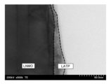
- FIG. It is a scanning transmission electron microscope image of Example 1 of the present invention, (a) represents the vicinity of the interface between the oxide active material and the coating layer, and (b) represents an enlarged region A of (a). It is a scanning transmission electron microscope image of Comparative Example 1 of the present invention.
- a lithium ion secondary battery 1 includes a positive electrode 2, a negative electrode 3, a non-aqueous electrolyte 5, and a separator 6, as shown in FIG. An external load 7 is connected.
- the positive electrode 2 is formed by stacking a positive electrode composite active material layer 11 on a positive electrode current collector 10, and is an intercalation electrode into which lithium ions can be intercalated and deintercalated.
- the positive electrode composite active material layer 11 contains a positive electrode composite active material 20, a conductive aid, and a binder.
- the negative electrode 3 is formed by stacking a negative electrode active material layer 13 on a negative electrode current collector 12, and is an intercalation electrode into which lithium ions can be intercalated and deintercalated.
- the negative electrode active material layer 13 contains a negative electrode active material 21, a conductive aid, and a binder.
- the positive electrode composite active material 20 is a coated positive electrode active material in which the surface of the oxide active material 30 is coated with the coating layer 31 .
- the oxide active material 30 is a lithium ion conductive active material, and has an average lithium desorption/insertion potential of 4.5 V or more with respect to the deposition potential of Li (also indicated as vs. Li + /Li)5. It is preferably 0 V or less. That is, the oxide active material 30 preferably has an operating potential of 4.5 V or more and 5.0 V or less based on lithium metal.
- the potential of lithium ion insertion/extraction reaction (hereinafter also referred to as voltage) (vs. Li + /Li) is, for example, the charge/discharge of a half-cell using the oxide active material 30 as the working electrode and the lithium metal as the counter electrode.
- the plateau with the lowest voltage value may be 4.5 V (vs. Li + /Li) or more, and the plateau with the highest voltage value is 5.0 V (vs. Li + / Li) or less.
- the oxide active material 30 is not particularly limited, a spinel-type lithium manganese oxide represented by the following formula (1) is preferable.
- x and y respectively satisfy 0 ⁇ x ⁇ 0.2 and 0 ⁇ y ⁇ 0.8
- M is Al, Mg, Zn, Ni, Co, Fe, Ti, Cu, and Cr. At least one selected from the group consisting of
- the particle diameter of the oxide active material 30 is not particularly limited, but the median diameter d50 is preferably 5 ⁇ m or more, more preferably 10 ⁇ m or more, and even more preferably 20 ⁇ m or more. Within this range, the difference from the particle size of the coating layer 31 can be ensured, and the coating of the coating layer 31 is facilitated.
- the median diameter d50 of the oxide active material 30 is preferably 100 ⁇ m or less, more preferably 80 ⁇ m or less, even more preferably 50 ⁇ m or less, and particularly preferably 30 ⁇ m or less.
- the coating layer 31 is composed of a lithium ion conductive oxide containing phosphorus as an element, and is preferably composed of an intercalation material that functions alone as a positive electrode active material.
- the lithium ion conductive oxide used in the coating layer 31 of the present embodiment is a lithium phosphate-based lithium ion conductive oxide represented by the following formula (1).
- LiaAbDcPO4 ( 1 ) (In the above formula (1), a, b, and c satisfy 0.9 ⁇ a ⁇ 1.1, 0 ⁇ b ⁇ 1, 0 ⁇ c ⁇ 1, 0.9 ⁇ b + c ⁇ 1.1, and A is at least one selected from the group consisting of Co, Mn, Ni, Fe, Cu and Cr, and D is Mg, Ca, Sr, Ba, Ti, Zn, B, Al, Ga, In, Si, Ge, Sc and at least one selected from the group consisting of Y.)
- the lithium ion conductive oxide forming the coating layer 31 preferably has an average particle diameter of 30 nm or more and 500 nm or less calculated using the X-ray small angle scattering method.
- the median diameter d50 of the oxide active material 30 is preferably 100 or more and 10000 or less, and more preferably 300 or more and 5000 or less when the average particle diameter of the lithium ion conductive oxide constituting the coating layer 31 is 1. more preferably 500 or more and 2000 or less, and particularly preferably 1000 or less.
- the coating of the lithium ion conductive oxide on the oxide active material 30 is preferred over the aggregation of the lithium ion conductive oxides and the formation of aggregates of the oxide active material 30 and the lithium ion conductive oxide. becomes dominant, and the lithium ion conductive oxide can easily cover the surface of the oxide active material 30 to form the coating layer 31 .
- the coating layer 31 is preferably 0.5 parts by mass or more, more preferably 1 part by mass or more, and even more preferably 2 parts by mass or more with respect to 100 parts by mass of the oxide active material 30. .
- the coating layer 31 is preferably 10 parts by mass or less, more preferably 5 parts by mass or less, and even more preferably 4 parts by mass or less with respect to 100 parts by mass of the oxide active material 30. .
- the coating layer 31 constitutes a continuous layer that closely covers the surface shape of the oxide active material 30 .
- the thickness of the coating layer 31 is thinner than the average particle size of the lithium ion conductive oxide, preferably 20 nm or less, more preferably 15 nm or less.
- the thickness of the coating layer 31 is preferably 5 nm or more. Within this range, it is possible to suppress the amount of gas generated while suppressing resistance loss in the coating layer 31 .
- Coating layer 31 is preferably amorphous in a range of 2 nm from the interface with oxide active material 30 from the viewpoint of reducing the interfacial resistance between oxide active material 30 and coating layer 31 . 90% or more of the region of the coating layer 31 is preferably amorphous, and 95% or more of the region is preferably amorphous.
- Lithium titanate is preferably used as the negative electrode active material 21 from the viewpoint that lithium deposition is less likely to occur and safety is improved.
- lithium titanates lithium titanate having a spinel structure is particularly preferable for the negative electrode active material 21 because the expansion and contraction of the active material in the reaction of intercalation and deintercalation of lithium ions is small.
- Lithium titanate may contain, for example, trace amounts of elements other than lithium and titanium, such as Nb.
- the conductive aid is not particularly limited, but a carbon material is preferable.
- the carbon material is preferably at least one selected from natural graphite, artificial graphite, vapor-grown carbon fiber, carbon nanotube, acetylene black, ketjen black, and furnace black.
- the amount of the conductive aid contained in the positive electrode 2 is preferably 1 part by weight or more and 30 parts by weight or less with respect to 100 parts by weight of the positive electrode composite active material 20 .
- the amount of the conductive aid contained in the negative electrode 3 is preferably 1 part by weight or more and 30 parts by weight or less with respect to 100 parts by weight of the negative electrode active material 21 .
- the binder is not particularly limited, but for both the positive electrode 2 and the negative electrode 3, for example, from the group consisting of polyvinylidene fluoride (PVdF), polytetrafluoroethylene (PTFE), styrene-butadiene rubber, polyimide, and derivatives thereof At least one selected can be used.
- PVdF polyvinylidene fluoride
- PTFE polytetrafluoroethylene
- styrene-butadiene rubber polyimide
- derivatives thereof At least one selected can be used.
- the binder is preferably dissolved or dispersed in a non-aqueous solvent or water for ease of production of the positive electrode 2 and the negative electrode 3 .
- Non-aqueous solvents include, but are not limited to, N-methyl-2-pyrrolidone (NMP), dimethylformamide, dimethylacetamide, methyl ethyl ketone, methyl acetate, ethyl acetate, and tetrahydrofuran.
- NMP N-methyl-2-pyrrolidone
- dimethylformamide dimethylacetamide
- methyl ethyl ketone methyl acetate
- ethyl acetate tetrahydrofuran.
- a dispersant and a thickener may be added to these.
- the amount of the binder contained in the positive electrode 2 is preferably 1 part by weight or more and 30 parts by weight or less with respect to 100 parts by weight of the positive electrode composite active material 20 .
- the amount of the binder contained in the negative electrode 3 is preferably 1 part by weight or more and 30 parts by weight or less with respect to 100 parts by weight of the negative electrode active material 21 .
- the current collectors 10 and 12 are not particularly limited, but are preferably made of aluminum or an aluminum alloy because they are stable under the positive electrode reaction atmosphere and the negative electrode reaction atmosphere, and are JIS standard 1030, 1050, 1085, 1N90, 1N99. High-purity aluminum represented by, for example, is more preferable.
- the current collectors 10 and 12 may also be made of a metal other than aluminum (copper, SUS, nickel, titanium, and alloys thereof) coated with a metal that does not react with the potentials of the positive electrode 2 and negative electrode 3 .
- the non-aqueous electrolytic solution 5 is not particularly limited, but may be a non-aqueous electrolytic solution in which a solute is dissolved in a non-aqueous solvent, a gel electrolyte in which a polymer is impregnated with a non-aqueous electrolytic solution in which a solute is dissolved in a non-aqueous solvent, or the like. can be used.
- the non-aqueous solvent preferably contains a cyclic aprotic solvent and/or a chain aprotic solvent.
- cyclic aprotic solvents include cyclic carbonates, cyclic esters, cyclic sulfones and cyclic ethers.
- chain aprotic solvent a chain carbonate, a chain carboxylic acid ester, a chain ether, and a solvent generally used as a solvent for non-aqueous electrolytes, such as acetonitrile, may be used.
- aprotic solvents include dimethyl carbonate, methyl ethyl carbonate, diethyl carbonate, dipropyl carbonate, methyl propyl carbonate, ethylene carbonate, propylene carbonate, butylene carbonate, ⁇ -butyl lactone, 1,2-dimethoxy Ethane, sulfolane, dioxolane, methyl propionate, and the like can be used. These solvents may be used singly or in combination of two or more kinds. is preferably used.
- dimethyl carbonate, methyl ethyl carbonate, diethyl carbonate, dipropyl carbonate, and methyl propyl carbonate have high stability at high temperatures and high lithium conductivity at low temperatures. It is preferable to mix one or more of the chain carbonates exemplified in (1) with one or more of the cyclic compounds exemplified by ethylene carbonate, propylene carbonate, butylene carbonate, and ⁇ -butyl lactone.
- Particularly preferred is a mixture of one or more chain carbonates exemplified by dimethyl carbonate, methylethyl carbonate and diethyl carbonate and one or more cyclic carbonates exemplified by ethylene carbonate, propylene carbonate and butylene carbonate.
- the solute used in the non-aqueous electrolyte 5 is not particularly limited, but examples include LiClO 4 , LiBF 4 , LiPF 6 , LiAsF 6 , LiCF 3 SO 3 , LiBOB (Lithium Bis (Oxalato) Borate), LiN(SO 2 CF 3 ) 2 and the like are preferable because they are easily dissolved in a solvent.
- the non-aqueous electrolyte 5 may further contain a vinyl group-containing cyclic siloxane such as 2,4,6,8-tetravinyl-2,4,6,8-tetramethylcyclotetrasiloxane (4VC4S) as an additive. good.
- a vinyl group-containing cyclic siloxane such as 2,4,6,8-tetravinyl-2,4,6,8-tetramethylcyclotetrasiloxane (4VC4S) as an additive. good.
- the non-aqueous electrolyte 5 may be included in the positive electrode 2, the negative electrode 3, and the separator 6 in advance, or after winding or laminating the separator 6 between the positive electrode 2 side and the negative electrode 3 side. may be added.
- the separator 6 is placed between the positive electrode 2 and the negative electrode 3, and may have any structure as long as it is insulating and can contain the non-aqueous electrolytic solution 5. As shown in FIG. Examples of the separator 6 include nylon, cellulose, polysulfone, polyethylene, polypropylene, polybutene, polyacrylonitrile, polyimide, polyamide, polyethylene terephthalate, and woven fabrics, nonwoven fabrics, microporous membranes, etc. of composites of two or more thereof. .
- the separator 6 may contain various plasticizers, antioxidants, and flame retardants, or may be coated with metal oxide or the like.
- the method for manufacturing the lithium ion secondary battery 1 of the present embodiment mainly includes an active material forming step for forming the positive electrode composite active material 20, a positive electrode forming step for forming the positive electrode 2, and a negative electrode forming step for forming the negative electrode 3. and a secondary battery assembling process for assembling the positive electrode 2, the negative electrode 3, and the non-aqueous electrolyte 5.
- the negative electrode forming process and the secondary battery assembling process are the same as the conventional processes, so the description is omitted. do.
- the lithium ion conductive oxide is pulverized by a pulverizing device such as a ball mill to form lithium ion conductive oxide particles (pulverization step).
- the lithium ion conductive oxide is a phosphorus-containing lithium ion conductive oxide similar to that of the coating layer 31 described above, and can be selected from materials similar to those of the coating layer 31 described above.
- the lithium ion conductive oxide before the pulverization step is phosphate compound particles having an olivine-type crystal structure, and the lithium ion conductive oxide particles after pulverization partially have a crystal structure. Destroyed and completely or partially amorphous.
- XRD X-ray diffraction
- the lithium ion conductive oxide particles preferably have a BET specific surface area of 20 m 2 /g or more and 80 m 2 /g or less.
- the lithium ion conductive oxide particles preferably have a BET specific surface area equivalent diameter (dBET) of 30 nm or more, more preferably 50 nm or more.
- the lithium ion conductive oxide particles preferably have a BET specific surface area equivalent diameter (dBET) of 500 nm or less, more preferably 450 nm or less.
- the lithium ion conductive oxide particles (phosphate-based compound particles) pulverized in a pulverization step are dispersed in a dispersion solvent to form a fine particle fluid (fine particle fluid forming step).
- the dispersion solvent used at this time is preferably one or a plurality of alcohol solutions, and more preferably ethanol from the viewpoint of volatility and safety.
- the particulate fluid formed at this time is a transparent sol in a sol state, and is an electrolytic sol having fluidity.
- the oxide active material A coating layer 31 is formed on the surface of the oxide active material 30 by a mechanical coating method for mechanically contacting the material 30 and the lithium ion conductive oxide in the fine particle fluid.
- the particulate fluid is ground into the oxide active material 30 by a grinding device such as a grinding mill to form a ground material (ground material forming step).
- the treatment temperature in the grinding device is preferably 5° C. or higher, more preferably 8° C. or higher, and even more preferably 10° C. or higher.
- the treatment temperature in the grinding device is preferably 120° C. or less, more preferably 100° C. or less, further preferably 80° C. or less, and even more preferably 70° C. or less.
- the temperature is preferably 50° C. or lower, and particularly preferably 50° C. or lower.
- the treatment time in the grinding device at this time is preferably 5 minutes or longer, more preferably 10 minutes or longer.
- the processing time in the grinding device at this time is preferably 90 minutes or less, more preferably 60 minutes or less.
- the atmosphere in the grinding device is preferably an inert gas atmosphere or an air atmosphere.
- the ground material is heat-treated to remove the dispersion solvent from the ground material to form the positive electrode composite active material 20 (removal step).
- the heat treatment temperature at this time is preferably over 50° C., more preferably 100° C. or higher, even more preferably 300° C. or higher, and particularly preferably 350° C. or higher. If the heat treatment temperature is lower than 50° C., the adhesion between the oxide active material 30 and the coating layer 31 becomes insufficient, and the coating layer 31 may peel off during charging and discharging of the battery, leading to deterioration of the long-term reliability of the battery. . On the other hand, if the heat treatment temperature is too high, the crystal structure of the coating layer 31 may change, the Li ion conductivity may decrease, and the battery may not charge and discharge normally. Therefore, the heat treatment temperature is preferably less than 600.degree. C., and more preferably 500.degree.
- the heat treatment time is preferably 30 minutes or longer, more preferably 1 hour or longer. Although the upper limit of the heat treatment time is not particularly limited, it is, for example, 3 hours or less. The above is the active material forming step.
- the positive electrode forming step is performed.
- the positive electrode composite active material 20 obtained in the active material forming step is mixed with a conductive aid and a binder to prepare a positive electrode mixture, and the positive electrode mixture is applied to the positive electrode current collector 10 ( positive electrode coating step).
- the positive electrode current collector 10 coated with the positive electrode mixture is dried to form the positive electrode 2 (positive electrode drying step).
- the above is the positive electrode forming process.
- the positive electrode 2 formed by the positive electrode forming process described above is assembled together with the negative electrode 3 formed by the negative electrode forming process and the non-aqueous electrolyte 5 in the same manner as in the prior art to complete the lithium ion secondary battery 1 .
- the coating layer 31 uniformly covers the oxide active material 30, so the area in contact with the non-aqueous electrolyte 5 is reduced and gas generation can be suppressed. Further, even if the non-aqueous electrolyte 5 and the additive are partially decomposed, the decomposed product can fill the gaps in the coating of the coating layer 31 to form a good film, so further decomposition of the non-aqueous electrolyte 5 can be suppressed. It becomes possible.
- the oxide active material 30 is composed of a lithium manganese oxide having a spinel crystal structure
- the coating layer 31 is a phosphate-based material that can be used as a positive electrode active material. Composed of compounds. Therefore, lithium ion insertion/extraction reactions tend to occur smoothly.
- the positive electrode composite active material 20 of the present embodiment since the vicinity of the interface between the coating layer 31 and the oxide active material 30 is amorphous, the volume change of the oxide active material 30 with the progress of charging and discharging is The amorphous portion of the coating layer 31 functions as a buffer even if a crack occurs. Therefore, cracking and peeling of the coating layer 31 are less likely to occur.
- the fine particle fluid in which the lithium ion conductive oxide particles are dispersed in the dispersion solvent is ground into the oxide active material 30, and the Since the heat treatment is applied, a thin coating layer 31 of good quality can be formed on the surface of the oxide active material 30 while maintaining the amorphous state.
- each constituent member can be freely replaced or added between the embodiments.
- Example 1 (i) Preparation of positive electrode First, lithium iron phosphate (LiFePO 4 , hereinafter also referred to as LFP) powder having a surface area of 9.5 m 2 /g and a median diameter of 1.5 ⁇ m was mixed with a predetermined amount of ethanol as a solvent, Planetary ball milling was performed for 3 hours using zirconia balls with a diameter of 0.5 mm. After removing the zirconia balls from the treated mixture with a sieve, the mixture was dried at 120° C. to remove the ethanol. As a result, LFP fine powder having a BET value (BET surface area) of 20 m 2 /g to 80 m 2 /g was obtained. Next, the LFP fine powder was mixed with ethanol to obtain a slurry (fine particle fluid) in which the LFP fine powder was dispersed in ethanol with a solid content of 16.4% by weight.
- LFP lithium iron phosphate
- LNMO Spinel-type lithium nickel manganate
- a grinding mill manufactured by Hosokawa Micron Corporation, product name: Nobilta
- a rotor load power 1.5 kW. was added in two batches so that the amount of added was 4.5 g (equivalent to 2.4 wt %).
- the rotor rotation speed was kept in the range of 2600 rpm to 3000 rpm, and the mixture was treated at room temperature for 10 minutes in an air atmosphere to obtain an LNMO surface-coated with LFP (hereinafter also referred to as surface-coated LNMO).
- the resulting surface-coated LNMO was heat-treated at 350° C. for 1 hour to obtain a positive electrode composite active material.
- PVdF polyvinylidene fluoride
- a slurry was prepared by dispersing the mixture in N-methyl-2-pyrrolidone (NMP).
- NMP N-methyl-2-pyrrolidone
- the binder used was prepared in an N-methyl-2-pyrrolidone (NMP) solution having a solid concentration of 5% by weight, and NMP was further added to adjust the viscosity so as to facilitate the later-described coating.
- the positive electrode was produced by vacuum drying at 170°C.
- the negative electrode was produced by vacuum-drying at 170°C.
- Two sheets of aluminum laminate films were prepared as exterior materials, and after forming a recess for the battery portion and a recess for the gas trapping portion by pressing, the electrode laminate was put therein.
- the outer periphery leaving a space for non-aqueous electrolyte injection is heat-sealed at 180 ° C.
- ethylene carbonate, propylene carbonate, and ethyl methyl carbonate are removed from the unsealed portion on a volume basis, ethylene carbonate/propylene carbonate/ LiPF 6 was dissolved in a solvent mixed with ethyl methyl carbonate at a ratio of 15/15/70 at a ratio of 1 mol/L, and after adding a nonaqueous electrolyte, the unsealed portion was heated to 180°C for 7 seconds while reducing the pressure. It was heat sealed with The obtained battery was subjected to constant current charging at a current value corresponding to 0.2 C until the battery voltage reached the final voltage of 3.4 V, and charging was stopped. Then, after standing in an environment of 60° C.
- Example 2 was obtained in the same manner as in Example 1, except that the coating amount of LFP fine powder was adjusted to 6.9 g (equivalent to 3.6 wt %) in the preparation of the positive electrode.
- Li 1.3 Al 0.3 Ti 1.7 (PO 4 ) 3 (hereinafter also referred to as LATP) was prepared as an active material for the positive electrode by the following method.
- a predetermined amount of Li 2 CO 3 , AlPO 4 , TiO 2 , NH 4 H 2 PO 4 and ethanol as a solvent were mixed as starting materials, and subjected to planetary ball mill treatment at 150 G for 1 hour using zirconia balls with a diameter of 3 mm. . After removing the zirconia balls from the treated mixture with a sieve, the mixture was dried at 120° C. to remove the ethanol. Thereafter, treatment was performed at 800° C. for 2 hours to obtain LATP powder.
- Comparative Example 1 was prepared in the same manner as in Example 1 except that the LATP powder described above was used.
- Comparative Example 2 was prepared in the same manner as in Comparative Example 1, except that the coating amount of the LATP fine powder was adjusted to 6.9 g (equivalent to 3.6 wt %) in the preparation of the positive electrode.
- Comparative Example 3 was prepared in the same manner as in Example 1, except that LNMO without surface coating was used in the preparation of the positive electrode.
- Comparative Example 4 was prepared in the same manner as in Example 1, except that the surface-coated LNMO was heat-treated at 600° C. for 1 hour in the preparation of the positive electrode.
- Comparative Example 5 was prepared in the same manner as in Example 1, except that the surface-coated LNMO was heat-treated at 50° C. for 1 hour in the preparation of the positive electrode.
- Comparative Example 7 (i) In the preparation of the positive electrode, LFP fine powder was dispersed in ethanol, and LNMO was added while stirring so that the weight of the LFP fine powder was 3%, and stirring was continued for 1 hour. Thereafter, ethanol was removed under reduced pressure and then heated at 120° C. to further remove ethanol to obtain LNMO surface-coated with LFP. The resulting surface-coated LNMO was heat treated at 350° C. for 1 hour. Comparative Example 7 was obtained in the same manner as Example 1, except that the surface-coated LNMO was used to prepare the positive electrode.
- the weight of the lithium ion secondary battery was measured with an electronic balance.
- the weight in water was measured using a hydrometer (manufactured by Alpha Mirage Co., Ltd., product number: MDS-3000), and the buoyancy was calculated by taking the difference between these weights.
- the volume of the lithium ion secondary battery was calculated by dividing this buoyancy by the density of water (1.0 g/cm 3 ).
- the amount of generated gas was calculated by comparing the volume after aging (that is, the volume after charging by applying voltage and then discharging) and the volume after the following cycle characteristic evaluation. Those with a gas generation amount of 5 ml or less were judged to be good.
- the stability of the cycle characteristics was evaluated by taking the discharge capacity at the 500th time assuming that the discharge capacity at the first time was 100, as a discharge capacity retention rate (%). A discharge capacity retention rate of 90% or more at the 500th cycle was judged as good, and a discharge capacity retention rate of less than 90% was judged as unsatisfactory.
- Example 1 and 2 and Comparative Examples 1-3 are shown in Table 1, and the evaluation results of Example 1 and Comparative Examples 4-7 are shown in Table 2. Further, a scanning transmission electron microscope image of Example 1 is shown in FIG. 2, and a scanning transmission electron microscope image of Comparative Example 1 is shown in FIG.
- Examples 1 and 2 using LFP as the coating layer had comparable capacity retention rates and a small amount of gas generation compared to Comparative Examples 1 and 2 using LATP as the coating layer. became.
- the thickness of the coating layer was thicker than the particle size before grinding, whereas Examples 1 and 2 using LFP as the coating layer In , the thickness of the coating layer was thinner than the particle size before milling.
- the amount of gas generated was less than in Comparative Example 3 in which LNMO was not coated with LFP, and the capacity retention ratio was high.
- the gas generation amount was 10 ml or less and the capacity retention rate was 90% or more, and the gas generation amount was compared to other Comparative Examples 4 to 7 coated with LFP. was small and the capacity retention ratio was high.
- the heat treatment temperature is preferably in the range of more than 50° C. and less than 600° C., and more preferably 100° C. or more and 500° C. or less. It was suggested.
- Example 1 compared to Comparative Example 6, in which the pulverization time in the pulverization step was short and the particle size was large, the amount of generated gas was small and the capacity retention ratio was high. That is, in Example 1 with a large BET surface area, compared to Comparative Example 6 with a small BET surface area, the amount of generated gas was small and the capacity retention ratio was high. From this result, it was suggested that the amount of generated gas can be reduced and the capacity retention rate can be increased by reducing the size of the particle size of the LFP fine powder and increasing the surface area.
- Example 1 in which LFP was coated by mechanical coating, produced a smaller amount of generated gas and a higher capacity retention rate than Comparative Example 7, in which LFP was coated by evaporation to dryness. From this result, it was suggested that by coating the LFP with mechanical coating, the amount of generated gas can be reduced and the capacity retention rate can be improved.
- Example 1 As shown in FIG. 2(a), a continuous LFP layer of 5 nm to 15 nm was confirmed on the surface of the LNMO. That is, the coating layer of Example 1 was a thin and uniform layer, and the difference between the maximum thickness and the minimum thickness was within 15 nm. In LNMO, regular lattice fringes were confirmed as shown in FIG. 2(b), suggesting that the spinel crystal structure was maintained. On the other hand, no lattice fringes were observed throughout the LFP, suggesting that it was amorphous at least in the range of 2 nm from the interface with the LNMO.
- the coating layer of Comparative Example 1 has an distorted shape with different thicknesses depending on the position as shown in FIG. It was a layer. This suggests that a thin and uniform layer can be formed by forming the coating layer with LFP.
Landscapes
- Chemical & Material Sciences (AREA)
- Chemical Kinetics & Catalysis (AREA)
- Electrochemistry (AREA)
- General Chemical & Material Sciences (AREA)
- Engineering & Computer Science (AREA)
- Manufacturing & Machinery (AREA)
- Inorganic Chemistry (AREA)
- Composite Materials (AREA)
- Materials Engineering (AREA)
- Crystallography & Structural Chemistry (AREA)
- Battery Electrode And Active Subsutance (AREA)
Priority Applications (3)
| Application Number | Priority Date | Filing Date | Title |
|---|---|---|---|
| US18/836,262 US20250219060A1 (en) | 2022-02-07 | 2023-01-27 | Positive electrode composite active material and method for producing positive electrode composite active material |
| JP2023578534A JPWO2023149363A1 (https=) | 2022-02-07 | 2023-01-27 | |
| CN202380020459.5A CN118648136A (zh) | 2022-02-07 | 2023-01-27 | 正极复合活性物质及正极复合活性物质的制造方法 |
Applications Claiming Priority (2)
| Application Number | Priority Date | Filing Date | Title |
|---|---|---|---|
| JP2022-017263 | 2022-02-07 | ||
| JP2022017263 | 2022-02-07 |
Publications (1)
| Publication Number | Publication Date |
|---|---|
| WO2023149363A1 true WO2023149363A1 (ja) | 2023-08-10 |
Family
ID=87552403
Family Applications (1)
| Application Number | Title | Priority Date | Filing Date |
|---|---|---|---|
| PCT/JP2023/002566 Ceased WO2023149363A1 (ja) | 2022-02-07 | 2023-01-27 | 正極複合活物質及び正極複合活物質の製造方法 |
Country Status (4)
| Country | Link |
|---|---|
| US (1) | US20250219060A1 (https=) |
| JP (1) | JPWO2023149363A1 (https=) |
| CN (1) | CN118648136A (https=) |
| WO (1) | WO2023149363A1 (https=) |
Cited By (1)
| Publication number | Priority date | Publication date | Assignee | Title |
|---|---|---|---|---|
| EP4641676A1 (en) * | 2024-04-24 | 2025-10-29 | Samsung Sdi Co., Ltd. | Positive electrode active material for rechargeable lithium battery, positive electrode including the same and rechargeable lithium battery including the same |
Citations (7)
| Publication number | Priority date | Publication date | Assignee | Title |
|---|---|---|---|---|
| JP2007103339A (ja) * | 2005-09-08 | 2007-04-19 | Sanyo Electric Co Ltd | 非水電解質二次電池 |
| JP2011502332A (ja) * | 2007-10-29 | 2011-01-20 | デジョン イーエム カンパニー リミテッド | リチウム二次電池用正極活物質、その製造方法、これを含むリチウム二次電池の正極及びリチウム二次電池 |
| JP2013191540A (ja) * | 2012-03-13 | 2013-09-26 | Samsung Corning Precision Materials Co Ltd | 正極活物質およびその製造方法並びにこれを利用した2次電池 |
| JP2016170942A (ja) * | 2015-03-12 | 2016-09-23 | トヨタ自動車株式会社 | 固体電池用正極活物質の製造方法 |
| JP2018116856A (ja) * | 2017-01-19 | 2018-07-26 | トヨタ自動車株式会社 | リチウムイオン二次電池用正極活物質 |
| CN112514109A (zh) * | 2018-04-19 | 2021-03-16 | A123系统有限责任公司 | 用于涂层阴极材料的方法和系统以及涂层阴极材料的用途 |
| JP2021136206A (ja) * | 2020-02-28 | 2021-09-13 | 太平洋セメント株式会社 | リチウムイオン二次電池用正極活物質複合体の製造方法 |
-
2023
- 2023-01-27 CN CN202380020459.5A patent/CN118648136A/zh active Pending
- 2023-01-27 US US18/836,262 patent/US20250219060A1/en active Pending
- 2023-01-27 WO PCT/JP2023/002566 patent/WO2023149363A1/ja not_active Ceased
- 2023-01-27 JP JP2023578534A patent/JPWO2023149363A1/ja active Pending
Patent Citations (7)
| Publication number | Priority date | Publication date | Assignee | Title |
|---|---|---|---|---|
| JP2007103339A (ja) * | 2005-09-08 | 2007-04-19 | Sanyo Electric Co Ltd | 非水電解質二次電池 |
| JP2011502332A (ja) * | 2007-10-29 | 2011-01-20 | デジョン イーエム カンパニー リミテッド | リチウム二次電池用正極活物質、その製造方法、これを含むリチウム二次電池の正極及びリチウム二次電池 |
| JP2013191540A (ja) * | 2012-03-13 | 2013-09-26 | Samsung Corning Precision Materials Co Ltd | 正極活物質およびその製造方法並びにこれを利用した2次電池 |
| JP2016170942A (ja) * | 2015-03-12 | 2016-09-23 | トヨタ自動車株式会社 | 固体電池用正極活物質の製造方法 |
| JP2018116856A (ja) * | 2017-01-19 | 2018-07-26 | トヨタ自動車株式会社 | リチウムイオン二次電池用正極活物質 |
| CN112514109A (zh) * | 2018-04-19 | 2021-03-16 | A123系统有限责任公司 | 用于涂层阴极材料的方法和系统以及涂层阴极材料的用途 |
| JP2021136206A (ja) * | 2020-02-28 | 2021-09-13 | 太平洋セメント株式会社 | リチウムイオン二次電池用正極活物質複合体の製造方法 |
Cited By (1)
| Publication number | Priority date | Publication date | Assignee | Title |
|---|---|---|---|---|
| EP4641676A1 (en) * | 2024-04-24 | 2025-10-29 | Samsung Sdi Co., Ltd. | Positive electrode active material for rechargeable lithium battery, positive electrode including the same and rechargeable lithium battery including the same |
Also Published As
| Publication number | Publication date |
|---|---|
| JPWO2023149363A1 (https=) | 2023-08-10 |
| US20250219060A1 (en) | 2025-07-03 |
| CN118648136A (zh) | 2024-09-13 |
Similar Documents
| Publication | Publication Date | Title |
|---|---|---|
| CN106025191B (zh) | 锂离子二次电池用正极活性物质、锂离子二次电池用正极以及锂离子二次电池 | |
| US8178238B2 (en) | Positive-electrode active material for lithium-ion secondary battery, positive electrode, manufacturing method thereof, and lithium-ion secondary battery | |
| JP7358363B2 (ja) | 被覆正極活物質及びリチウムイオン二次電池の製造方法 | |
| CN107408686A (zh) | 用于锂离子二次电池的阴极活性物质、其制造方法及包含其的锂离子二次电池 | |
| JP7403908B2 (ja) | 導電材、これを含む電極形成用スラリー、電極及びこれを用いて製造されるリチウム二次電池 | |
| JP7612642B2 (ja) | 正極活物質及びこれを含むリチウム二次電池 | |
| CN104718657B (zh) | 锂二次电池 | |
| CN107834102B (zh) | 锂离子二次电池和其制造方法 | |
| JP5505479B2 (ja) | リチウムイオン二次電池用負極及びその負極を用いたリチウムイオン二次電池 | |
| US20240154106A1 (en) | Negative electrode active material, negative electrode material and battery | |
| JP7653633B2 (ja) | 二次電池用負極およびその製造方法ならびに二次電池 | |
| JP2016189321A (ja) | リチウムイオン二次電池用正極活物質、リチウムイオン二次電池用正極およびこれを用いたリチウムイオン二次電池 | |
| JP2022146538A (ja) | リチウムイオン二次電池用正極の製造方法 | |
| JP7766431B2 (ja) | 正極複合活物質、リチウムイオン二次電池、複合活物質、正極複合活物質の製造方法、及びリチウムイオン二次電池の製造方法 | |
| JP2019164880A (ja) | リチウムイオン二次電池用正極活物質、リチウムイオン二次電池用正極およびこれを用いたリチウムイオン二次電池 | |
| JP7695803B2 (ja) | リチウムイオン二次電池用正極活物質及びリチウムイオン二次電池の製造方法 | |
| KR101796248B1 (ko) | 리튬이차전지용 양극활물질 및 그 제조방법 | |
| US20240014451A1 (en) | Positive electrode composite active substance, lithium ion secondary battery, composite active substance, method for producing positive electrode composite active substance, and method for producing lithium ion secondary battery | |
| US20250219060A1 (en) | Positive electrode composite active material and method for producing positive electrode composite active material | |
| US20250015268A1 (en) | Positive electrode composite active material, lithium ion secondary battery, and production method for lithium ion secondary battery | |
| JP2019160577A (ja) | リチウムイオン二次電池用正極活物質、リチウムイオン二次電池用正極およびリチウムイオン二次電池 | |
| JP7163629B2 (ja) | 負極活物質、その製造方法、負極及び非水電解質蓄電素子 | |
| US10944098B2 (en) | Negative electrode active material particle, negative electrode, lithium-ion secondary battery, and production method of negative electrode active material particle | |
| JP2019160576A (ja) | リチウムイオン二次電池用正極活物質、リチウムイオン二次電池用正極およびリチウムイオン二次電池 | |
| JP2022154600A (ja) | リチウムイオン二次電池用負極活物質、及び、その製造方法 |
Legal Events
| Date | Code | Title | Description |
|---|---|---|---|
| 121 | Ep: the epo has been informed by wipo that ep was designated in this application |
Ref document number: 23749679 Country of ref document: EP Kind code of ref document: A1 |
|
| WWE | Wipo information: entry into national phase |
Ref document number: 2023578534 Country of ref document: JP |
|
| WWE | Wipo information: entry into national phase |
Ref document number: 202380020459.5 Country of ref document: CN |
|
| NENP | Non-entry into the national phase |
Ref country code: DE |
|
| 122 | Ep: pct application non-entry in european phase |
Ref document number: 23749679 Country of ref document: EP Kind code of ref document: A1 |
|
| WWP | Wipo information: published in national office |
Ref document number: 18836262 Country of ref document: US |