WO2023149066A1 - 美容成分噴霧装置 - Google Patents
美容成分噴霧装置 Download PDFInfo
- Publication number
- WO2023149066A1 WO2023149066A1 PCT/JP2022/044282 JP2022044282W WO2023149066A1 WO 2023149066 A1 WO2023149066 A1 WO 2023149066A1 JP 2022044282 W JP2022044282 W JP 2022044282W WO 2023149066 A1 WO2023149066 A1 WO 2023149066A1
- Authority
- WO
- WIPO (PCT)
- Prior art keywords
- contactor
- cosmetic
- component
- temperature
- ingredient
- Prior art date
- Legal status (The legal status is an assumption and is not a legal conclusion. Google has not performed a legal analysis and makes no representation as to the accuracy of the status listed.)
- Ceased
Links
Images














Classifications
-
- B—PERFORMING OPERATIONS; TRANSPORTING
- B05—SPRAYING OR ATOMISING IN GENERAL; APPLYING FLUENT MATERIALS TO SURFACES, IN GENERAL
- B05B—SPRAYING APPARATUS; ATOMISING APPARATUS; NOZZLES
- B05B17/00—Apparatus for spraying or atomising liquids or other fluent materials, not covered by the preceding groups
-
- A—HUMAN NECESSITIES
- A45—HAND OR TRAVELLING ARTICLES
- A45D—HAIRDRESSING OR SHAVING EQUIPMENT; EQUIPMENT FOR COSMETICS OR COSMETIC TREATMENTS, e.g. FOR MANICURING OR PEDICURING
- A45D20/00—Hair drying devices; Accessories therefor
- A45D20/04—Hot-air producers
- A45D20/08—Hot-air producers heated electrically
- A45D20/10—Hand-held drying devices, e.g. air douches
- A45D20/12—Details thereof or accessories therefor, e.g. nozzles, stands
-
- A—HUMAN NECESSITIES
- A45—HAND OR TRAVELLING ARTICLES
- A45D—HAIRDRESSING OR SHAVING EQUIPMENT; EQUIPMENT FOR COSMETICS OR COSMETIC TREATMENTS, e.g. FOR MANICURING OR PEDICURING
- A45D40/00—Casings or accessories specially adapted for storing or handling solid or pasty toiletry or cosmetic substances, e.g. shaving soaps or lipsticks
- A45D40/26—Appliances specially adapted for applying pasty paint, e.g. using roller, using a ball
-
- B—PERFORMING OPERATIONS; TRANSPORTING
- B05—SPRAYING OR ATOMISING IN GENERAL; APPLYING FLUENT MATERIALS TO SURFACES, IN GENERAL
- B05B—SPRAYING APPARATUS; ATOMISING APPARATUS; NOZZLES
- B05B7/00—Spraying apparatus for discharge of liquids or other fluent materials from two or more sources, e.g. of liquid and air, of powder and gas
- B05B7/0081—Apparatus supplied with low pressure gas, e.g. "hvlp"-guns; air supplied by a fan
-
- B—PERFORMING OPERATIONS; TRANSPORTING
- B05—SPRAYING OR ATOMISING IN GENERAL; APPLYING FLUENT MATERIALS TO SURFACES, IN GENERAL
- B05B—SPRAYING APPARATUS; ATOMISING APPARATUS; NOZZLES
- B05B7/00—Spraying apparatus for discharge of liquids or other fluent materials from two or more sources, e.g. of liquid and air, of powder and gas
- B05B7/16—Spraying apparatus for discharge of liquids or other fluent materials from two or more sources, e.g. of liquid and air, of powder and gas incorporating means for heating or cooling the material to be sprayed
- B05B7/18—Spraying apparatus for discharge of liquids or other fluent materials from two or more sources, e.g. of liquid and air, of powder and gas incorporating means for heating or cooling the material to be sprayed the material having originally the shape of a wire, rod or the like
-
- A—HUMAN NECESSITIES
- A45—HAND OR TRAVELLING ARTICLES
- A45D—HAIRDRESSING OR SHAVING EQUIPMENT; EQUIPMENT FOR COSMETICS OR COSMETIC TREATMENTS, e.g. FOR MANICURING OR PEDICURING
- A45D19/00—Devices for washing the hair or the scalp; Similar devices for colouring the hair
- A45D19/02—Hand-actuated implements, e.g. hand-actuated spray heads
-
- A—HUMAN NECESSITIES
- A45—HAND OR TRAVELLING ARTICLES
- A45D—HAIRDRESSING OR SHAVING EQUIPMENT; EQUIPMENT FOR COSMETICS OR COSMETIC TREATMENTS, e.g. FOR MANICURING OR PEDICURING
- A45D2200/00—Details not otherwise provided for in A45D
- A45D2200/05—Details of containers
- A45D2200/054—Means for supplying liquid to the outlet of the container
- A45D2200/057—Spray nozzles; Generating atomised liquid
-
- A—HUMAN NECESSITIES
- A45—HAND OR TRAVELLING ARTICLES
- A45D—HAIRDRESSING OR SHAVING EQUIPMENT; EQUIPMENT FOR COSMETICS OR COSMETIC TREATMENTS, e.g. FOR MANICURING OR PEDICURING
- A45D2200/00—Details not otherwise provided for in A45D
- A45D2200/15—Temperature
- A45D2200/155—Heating or cooling means, i.e. for storing or applying cosmetic products at a predetermined temperature
Definitions
- the present disclosure relates to a cosmetic ingredient spraying device.
- Patent Document 1 discloses a cosmetic ingredient spraying device that includes an atomizing device that imparts liquid droplets to an airflow, and a cosmetic ingredient holding member that releases the retained cosmetic ingredient into the airflow using droplets contained in the airflow as media. is disclosed.
- the atomization device condenses moisture contained in the air to give droplets to the air flow.
- the droplets imparted to the airflow pass through the cosmetic-component retaining member, thereby eluting the retained cosmetic component.
- the droplets containing the eluted beauty ingredients are ejected from the ejection part together with the air flow.
- the cosmetic ingredient held in the cosmetic ingredient holding member is eluted into droplets.
- the amount of spray is decreasing. For this reason, the spray amount of the cosmetic ingredient cannot be controlled, and the spray amount of the cosmetic ingredient is not stable.
- An object of the present disclosure is to provide a cosmetic ingredient spraying device capable of stabilizing the amount of cosmetic ingredient sprayed.
- a cosmetic component spraying device comprises a component solid portion containing at least one type of cosmetic component that is solid or semi-solid at room temperature, a heatable contactor, the component solid portion and the contact portion.
- a drive connected to at least one selected from the group and configured to vary the physical distance between said component solid portion and said contact; and a controller for controlling the temperature of the contactor and the operation of the drive section, wherein the controller sets the temperature of the contactor to a melting point or sublimation point of the cosmetic ingredient or higher, and controls the drive section.
- the contact state between the solid component portion and the contactor is changed while the solid component portion and the contactor are kept in continuous contact, and the cosmetic component is atomized.
- FIG. 3 is a side view when the component solid portion is accommodated in the holding portion from the state shown in Fig. 2; It is a side view of a component solid part, a holding part, a drive part, a contactor, an elastic member, a heater, a thermocouple, and a force detection part of the cosmetic ingredient spraying device according to the present embodiment. It is a schematic diagram showing electrical connection between the control unit and each mechanism of the cosmetic ingredient spraying device according to the present embodiment.
- FIG. 10 is a schematic diagram showing another example of state change with respect to the extrusion speed between the component solid portion and the contactor of the cosmetic component spraying device according to the present embodiment.
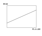
- FIG. 8 is a graph showing changes in the amount of cosmetic ingredients atomized with respect to the extrusion speed in FIGS. 6 and 7.
- FIG. It is a schematic diagram showing an example of the state change with respect to the pressing force between the component solid portion and the contactor of the cosmetic component spraying device according to the present embodiment.
- FIG. 11 is a graph showing changes in the amount of cosmetic ingredients atomized with time in FIGS. 9 and 10.
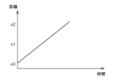
- Figure 13 is a graph showing the change in distance between the component solids and the contact over time in Figure 12;
- FIG. 13 is a graph showing changes in the amount of cosmetic ingredient atomized with respect to time in FIG. 12 ;
- FIG. 16 is a graph showing the change in distance between the component solid portion and the contact over time in FIG. 15; 16 is a graph showing changes in the amount of cosmetic ingredients atomized with respect to time in FIG. 15.
- FIG. 4 is a graph showing changes in the amount of cosmetic ingredient atomized with respect to time.
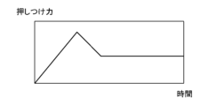
- FIG. 19 is a graph showing the change in compressive force between the component solid portion and the contact over time in FIG. 18; 4 is a graph showing changes in the amount of cosmetic ingredient atomized with respect to time.
- FIG. 21 is a graph showing the change in compressive force between the component solid portion and the contact over time in FIG.
- FIG. 20 is a graph showing changes in the atomization amount of cosmetic ingredient A with respect to temperature.
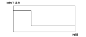
- FIG. 19 is a graph showing changes in contact temperature with time in FIG. 18;
- FIG. 21 is a graph showing the change in temperature of the contact over time in FIG. 20;
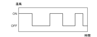
- FIG. 25 is a graph showing the timing when the air blower in FIG. 24 blows out hot air;
- FIG. 4 is a graph showing changes in the amount of cosmetic ingredient atomized with respect to time.
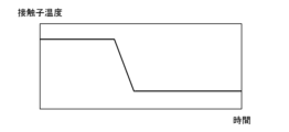
- FIG. 27 is a graph showing changes in contact temperature with time in FIG. 26;
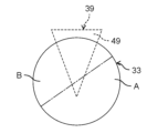
- Fig. 2 is a front view of the cosmetic component spraying device according to the present embodiment when the component solid portion contains a plurality of types of cosmetic components;
- FIG. 29 is a side view when the component solid portion is rotated from the state of FIG.
- FIG. 28 is a side view when the component solid portion is rotated from the state of FIG. 29;
- FIG. 31 is a graph showing the change in the percentage of cosmetic ingredient A in the atomized cosmetic ingredient with respect to the rotation angle of the component solid portion shown in FIGS. 28 to 30;
- FIG. FIG. 2 is a front view showing an example of arrangement of cosmetic ingredients when the component solid portion of the cosmetic ingredient spraying device according to the present embodiment contains a plurality of types of cosmetic ingredients.
- FIG. 10 is a front view showing another example of arrangement of cosmetic ingredients when the component solid portion of the cosmetic ingredient spraying device according to the present embodiment contains a plurality of types of cosmetic ingredients.
- 4 is a graph showing changes in the amount of atomized cosmetic ingredient B with respect to temperature.
- FIG. 10 is a graph showing changes in atomization amounts of cosmetic ingredients A and B with respect to temperature.
- FIG. 2 is a cross-sectional view of the cosmetic ingredient spraying device according to the present embodiment when it is equipped with an atomization amount detection unit; 10 is a graph showing other changes in the atomization amount of cosmetic ingredient A with respect to temperature.
- FIG. 1 is a cross-sectional view 1 of a cosmetic ingredient spraying device according to this embodiment.
- FIG. 2 is a side view of the component solid portion 33, the holding portion 35, the driving portion 37, and the contactor 39 of the cosmetic component spraying device 1 according to this embodiment.
- FIG. 3 is a side view when the component solid portion 33 is accommodated in the holding portion 35 from the state shown in FIG.
- FIG. 4 is a side view of the component solid portion 33, the holding portion 35, the driving portion 37, the contactor 39, the elastic member 41, the heater 51, the thermocouple 53, and the force detecting portion 55 of the cosmetic component spraying device 1 according to this embodiment. It is a diagram.
- FIG. 1 is a cross-sectional view 1 of a cosmetic ingredient spraying device according to this embodiment.
- FIG. 2 is a side view of the component solid portion 33, the holding portion 35, the driving portion 37, and the contactor 39 of the cosmetic component spraying device 1 according to this embodiment.
- FIG. 3 is a
- FIG. 5 is a schematic diagram showing electrical connections between the controller 9 and each mechanism of the cosmetic ingredient spraying device 1 according to this embodiment.
- a cosmetic ingredient spraying device 1 according to this embodiment is applied to, for example, a hair dryer.
- the cosmetic ingredient spraying device 1 includes a housing 3 , a blowing section 5 , an atomizing section 7 and a control section 9 .
- the housing 3 is formed in the shape of a housing capable of accommodating the air blowing section 5, the atomizing section 7, and the control section 9 inside.
- the housing 3 is provided with an intake port 11 that takes in outside air, and a blowout part 13 that blows out an airflow that has been adjusted inside.
- the ejection part 13 has an ejection port 15 for ejecting a large amount of air flow, and an ingredient ejection port 17 for ejecting atomized cosmetic ingredients together with the air flow.
- the ejection port 15 and the component ejection port 17 are separated by a partition wall 19 .
- the housing 3 is provided with a grip portion 21 that is gripped by the user.
- a power supply section 23 to which power is supplied from a power supply is provided at the end of the grip section 21 .
- a switch 25 is provided on the outer surface of the grip portion 21 to select whether or not to eject the cosmetic component from the ejection portion 13 .
- the outer surface of the grip portion 21 is provided with a power switch or the like for turning on/off the supply of power from the power source.
- the blower section 5 includes a fan 27, a fan motor 29, and a blower heater 31.
- the fan 27 is arranged between the suction port 11 and the ejection part 13 .
- the fan 27 rotates to take in the outside air from the suction port 11 and eject the airflow from the ejection portion 13 .
- the fan motor 29 is connected to the fan 27 and rotates the fan 27 by operating.
- the blower heater 31 is arranged between the fan 27 and the ejection part 13 .
- the blower heater 31 heats the air flow to warm air, and blows the warm air from the blowing part 13 .
- the atomizing part 7 includes a component solid part 33, a holding part 35, a driving part 37, a contactor 39, and an elastic member 41.
- the component solid portion 33 is formed in a cylindrical shape.
- the component solid portion 33 contains at least one cosmetic component that is solid or quasi-solid at room temperature.
- normal temperature is 25 degreeC.
- beauty ingredients include collagen, elastin, and keratin as proteins, and various peptides as peptides.
- beauty ingredients include, for example, amino acids such as lysine, phenylalanine, arginine, cysteine, and ceramides such as ceramides.
- cosmetic ingredients include, for example, organic acids such as succinic acid, maleic acid, fumaric acid, lactic acid, malic acid, tartaric acid, citric acid, and sebacic acid, and vitamins such as vitamins. Beauty ingredients include astaxanthin, lutein, and catechin as antioxidant ingredients, and isoflavone, dutasteride, and finasteride as hormones.
- cosmetic ingredients include, for example, lipids such as lauric acid, myristic acid, palmitic acid, stearic acid, stearyl alcohol, cholesterol, petrolatum, and coconut oil.
- lipids such as lauric acid, myristic acid, palmitic acid, stearic acid, stearyl alcohol, cholesterol, petrolatum, and coconut oil.
- beauty ingredients include sugars such as trehalose, dextrin, cyclodextrin, and maltitol.
- beauty ingredients include chitin as a polysaccharide, urea as others, and glycyrrhizic acid.
- the holding part 35 is formed in a circular tubular shape so that the component solid part 33 can be accommodated inside.
- the following three methods of solidification can be used.
- Solidification method 1 A cylindrical solidification container having both open inlets is provided, and both of the open inlets are entered. Lids are provided for each, and a predetermined amount of the cosmetic substance is put into the solidification container which is lubricated with fluororesin or the like. . A predetermined force is applied to the side that applies pressure to the cosmetic substance at least one lid portion. Furthermore, the solidification container is heated above the melting point. After a predetermined period of time has passed, one lid is removed, and the solidified cosmetic substance is extruded while it is hot with another lid, and then cooled at room temperature. If the cosmetic substance is water-soluble, it is desirable to add water to the cosmetic substance at a mass ratio of about 10% when applying pressure.
- Solidification method 2 A cosmetic substance is placed in a cylindrical solidification container with an upper opening, the solidification container is heated to a melting point or higher, and after a predetermined time has passed, it is cooled to room temperature.
- Solidification method 3 After the cosmetic substance is heated to a melting point or higher and sufficiently melted, it is poured into a cylindrical solidification container with an upper opening and cooled at room temperature.
- a helical screw 43 and a guide 45 extending along the axial direction are provided inside the holding portion 35 .
- the holding part 35 holds the component solid part 33 inside so that it can appear/retract and rotate.
- the component solid portion 33 held by the holding portion 35 is axially moved in a direction out of the holding portion 35 by the screw 43 and the guide 45 .
- the component solid portion 33 moves axially toward the direction of entering the holding portion 35 by means of the screw 43 and the guide 45 .
- the drive unit 37 is composed of, for example, a motor that can rotate in both forward and reverse directions.
- the driving portion 37 is arranged on one side of the holding portion 35 in the longitudinal direction, and the motor shaft is connected to the component solid portion 33 so as to be integrally rotatable.
- the driving portion 37 rotates the component solid portion 33 by being operated, and causes the component solid portion 33 to protrude and retract with respect to the holding portion 35 in the axial direction.
- the drive unit 37 may have, for example, a motor that rotates the solid component part 33 and a rod that moves the solid component part 33 in the axial direction, independently of each other. In this case, there is no need to provide the screw 43 or the guide 45 in the holding portion 35, and the holding portion 35 can be made simple in structure.
- the contactor 39 includes a fixed portion 47 and a contact portion 49 formed of a single member continuous with the fixed portion 47 .
- the fixing portion 47 extends along the length direction of the holding portion 35 and is fixed to the housing 3 .
- a heater 51 for heating the contactor 39 is provided inside the fixed portion 47 .
- the contact portion 49 is formed in a triangular shape and arranged to face the component solid portion 33 .
- the area of the contact portion 49 is set smaller than the area of the end surface of the component solid portion 33 .
- a thermocouple 53 for detecting the temperature of the contactor 39 is provided inside the contact portion 49 .
- the contactor 39 is heated by the heater 51 to the melting point or sublimation point of the cosmetic ingredient contained in the solid component portion 33 , and the contact portion 49 is brought into contact with the solid component portion 33 .
- the contact portion 49 contacts the solid component portion 33, the cosmetic component in the solid component portion 33 is atomized.
- the atomized cosmetic ingredients are mixed with the airflow and ejected together with the airflow from the component ejection port 17 of the ejection portion 13 .
- the elastic member 41 is made of, for example, an elastic spring. One end of the elastic member 41 abuts on a force detecting portion 55 for detecting a pressing force received from the component solid portion 33 fixed to the housing 3 , and the other end abuts on the contact portion 49 of the contactor 39 .
- the force detection section 55 also functions as a contact detection section that detects contact between the component solid portion 33 and the contactor 39 .
- the elastic member 41 is elastically deformed and receives a pressing force from the solid component portion 33 when the contact portion 49 contacts the solid component portion 33 . By receiving the pressing force from the component solid portion 33, the elastic member 41 can suppress variation in the contact pressure between the component solid portion 33 and the contactor 39, thereby suppressing variation in the atomization amount of the cosmetic component. can.
- the control unit 9 includes a heater 51 of the contactor 39, a thermocouple 53 of the contactor 39, a drive unit 37, a fan motor 29, a blower heater 31, and a switch 25. , and the force detection unit 55 .
- the control unit 9 includes, for example, a temperature adjustment circuit, a component drive circuit, and a blower drive circuit.
- the temperature adjustment circuit adjusts the heating of the heater 51 and adjusts the temperature of the contact 39 based on the temperature measured by the thermocouple 53 and the pressing force measured by the force detection unit 55 .
- the component drive circuit adjusts the operation of the drive unit 37 based on the temperature measured by the thermocouple 53 and the pressing force measured by the force detection unit 55, and adjusts the contact state between the component solid portion 33 and the contactor 39.
- the blower drive circuit adjusts the operation of the fan motor 29 and the blower heater 31 based on the temperature measured by the thermocouple 53 to adjust the air flow ejected from the ejector 13 .
- the control unit 9 has a built-in timer so that time can be measured.
- FIG. 6 is a schematic diagram showing an example of state change with respect to the extrusion speed between the component solid portion 33 and the contactor 39 of the cosmetic component spraying device 1 according to this embodiment. As shown in FIG.
- FIG. 7 is a schematic diagram showing another example of state change with respect to the extrusion speed between the component solid portion 33 and the contactor 39 of the cosmetic component spraying device 1 according to this embodiment. As shown in FIG. 7, if the movement speed (that is, extrusion speed) of the contactor 39 with respect to the component solid portion 33 is high, the component solid portion 33 and the contactor 39 will come into contact with each other per time as in states 1 to 7.
- FIG. 8 is a graph showing changes in the amount of cosmetic ingredient atomized with respect to the extrusion speed in FIGS. As shown in FIG. 8, the faster the contactor 39 pushes out, the more the cosmetic component is atomized.
- FIG. 9 is a schematic diagram showing an example of state change with respect to pressing force between the component solid portion 33 and the contactor 39 of the cosmetic component spraying device 1 according to this embodiment.
- FIG. 10 is a schematic diagram showing another example of state change with respect to pressing force between the component solid portion 33 and the contactor 39 of the cosmetic component spraying device 1 according to this embodiment.
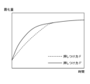
- FIG. 11 is a graph showing changes in the amount of cosmetic ingredient atomized with respect to time in FIGS. 9 and 10.
- FIG. 9 when the pressing force of the contactor 39 against the component solid portion 33 is small, the heat of the contactor 39 is less likely to be transmitted to the cosmetic component as in the states A to E, and the atomization amount of the cosmetic component is small. Become. On the other hand, as shown in FIG.
- the controller 9 heats the heater 51 of the contactor 39 when the switch 25 is turned on to raise the temperature of the contactor 39 to the melting point or sublimation point of the cosmetic ingredient or higher.
- the control unit 9 operates the driving unit 37 to bring the component solid portion 33 into contact with the contactor 39, thereby atomizing the cosmetic component.
- the control section 9 operates the drive section 37 to control the solid component section 33 to be in constant contact with the contactor 39 .
- the control section 9 controls the operation of the drive section 37 to change the contact state between the component solid section 33 and the contactor 39 .
- the atomized cosmetic ingredients are mixed with the airflow generated by the operation of the fan 27 and ejected to the outside from the ingredient ejection port 17 of the ejection section 13 .
- control unit 9 brings the contactor 39 heated above the melting point or sublimation point of the cosmetic ingredient into contact with the ingredient solid part 33 containing the cosmetic ingredient that is solid or semi-solid at room temperature, thereby misting the cosmetic ingredient. make it Therefore, until the cosmetic ingredient in the component solid portion 33 is completely atomized, the atomized amount of the cosmetic ingredient does not fluctuate, and the sprayed amount of the cosmetic ingredient can be stabilized.
- stabilizing the spray amount of the cosmetic ingredient for example, uneven adhesion of the cosmetic ingredient to the hair can be prevented.
- the control unit 9 operates the driving unit 37 while the atomized cosmetic ingredients are being ejected from the component ejection port 17 of the ejection unit 13, that is, while the switch 25 is on, so that the component solid portion 33 is always on. is brought into contact with the contactor 39. Therefore, when the atomized beauty ingredients are ejected from the ejection part 13, the beauty ingredients are always atomized, and the atomized beauty ingredients can be continuously ejected from the ejection part 13. ⁇ By continuously ejecting the atomized beauty ingredients from the ejection part 13, it is possible to prevent uneven adhesion of the beauty ingredients on the hair, for example.
- the control unit 9 controls the operation of the driving unit 37 and changes the contact state between the solid component part 33 and the contactor 39 .
- the control section 9 operates the driving section 37 so as to increase the pressing force of the solid ingredient section 33 against the contactor 39 .
- the control section 9 operates the drive section 37 so as to reduce the pressing force of the solid ingredient section 33 against the contactor 39 .
- FIG. 12 is a schematic diagram showing an example of state change with respect to pressing force between the component solid portion 33 and the contactor 39 of the cosmetic component spraying device 1 according to this embodiment.
- FIG. 13 is a graph showing the change in distance between component solid portion 33 and contactor 39 with time in FIG. FIG.
- FIG. 14 is a graph showing changes in the amount of cosmetic ingredient atomized with respect to time in FIG.
- FIG. 15 is a schematic diagram showing another example of state change with respect to pressing force between the component solid portion 33 and the contactor 39 of the cosmetic component spraying device 1 according to this embodiment.
- FIG. 16 is a graph showing the change in distance between component solid portion 33 and contactor 39 with time in FIG.
- FIG. 17 is a graph showing changes in the amount of cosmetic ingredient atomized with respect to time in FIG.
- FIG. 12 when the pressing force is continuously applied, the beauty ingredients in the ingredient solid portion 33 are continuously atomized as in states 1-5. Therefore, as shown in FIGS. 13 and 14, the distance between the component solid portion 33 and the contactor 39 continuously increases, and the atomization amount of the cosmetic component also increases continuously.
- the control unit 9 controls the operation of the driving unit 37 so that the component solid portion 33 continues to apply the pressing force to the contactor 39 when the atomization amount of the cosmetic component continues to increase.
- the control section 9 operates the driving section 37 so that the component solid portion 33 applies a pressing force to the contactor 39 for a predetermined period of time.
- the control unit 9 detects contact between the component solid portion 33 and the contactor 39 from the force detection unit 55, and measures a predetermined time. By controlling the pressing force of the control unit 9, the atomization amount of the cosmetic ingredient can be stabilized.
- the control unit 9 controls the operation of the drive unit 37 based on the pressing force measured by the force detection unit 55, and adjusts the pressing force of the component solid portion 33 against the contactor 39, thereby adjusting the atomization amount of the cosmetic component. adjust.
- the control unit 9 controls the operation of the drive unit 37 based on the pressing force measured by the force detection unit 55 , so that the ejection unit 13 can eject an optimum atomization amount of the cosmetic component.
- FIG. 18 is a graph showing changes in the amount of cosmetic ingredients atomized over time.
- FIG. 19 is a graph showing changes in pressing force between component solid portion 33 and contactor 39 with time in FIG.
- FIG. 20 is a graph showing changes in the amount of cosmetic ingredient atomized over time.
- FIG. 21 is a graph showing changes in pressing force between component solid portion 33 and contactor 39 with time in FIG.
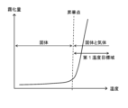
- FIG. 22 is a graph showing changes in the amount of atomized cosmetic ingredient A with respect to temperature.
- FIG. 37 is a graph showing other changes in the atomization amount of cosmetic ingredient A with respect to temperature. For example, assume that the temperature of the contactor 39 is equal to or higher than the boiling point of the cosmetic component, and the atomization amount of the cosmetic component changes from the target atomization amount as shown in FIG.
- the control unit 9 operates the driving unit 37 based on the pressing force measured by the force detection unit 55, and increases the pressing force until a predetermined time. Then, after a predetermined time has passed, the control unit 9 operates the driving unit 37 based on the pressing force measured by the force detection unit 55, reduces the pressing force, and maintains the pressing force at the predetermined pressing force.
- the control unit 9 operates the driving unit 37 based on the pressing force measured by the force detection unit 55, and increases the pressing force until a predetermined time.
- the control section 9 operates the driving section 37 based on the pressing force measured by the force detecting section 55, and reduces the pressing force until a predetermined period of time.
- the control unit 9 operates the driving unit 37 based on the pressing force measured by the force detection unit 55, and increases the pressing force until a predetermined time.
- the control section 9 operates the driving section 37 based on the pressing force measured by the force detecting section 55, and reduces the pressing force until a predetermined period of time.
- the control unit 9 operates the driving unit 37 based on the pressing force measured by the force detection unit 55, and increases the pressing force until the predetermined time.
- the cosmetic component when the cosmetic component reaches the melting point, it changes from solid to liquid, and when it reaches the boiling point, it changes from liquid to gas and atomizes.
- FIG. 37 for example, when the cosmetic component reaches the sublimation point, it changes from a solid to a gas and atomizes.
- cosmetic ingredients are atomized when they reach the melting point or sublimation point.
- the atomization amount of the cosmetic ingredient gradually increases as the temperature rises in the range above the melting point or sublimation point and below the boiling point.
- the atomization amount of cosmetic ingredients increases sharply as the temperature rises above the boiling point.
- the upper limit of the region above the boiling point is the decomposition point of the cosmetic ingredients.
- the controller 9 heats the heater 51 based on the temperature measured by the thermocouple 53 in the first temperature target range above the melting point or sublimation point and below the boiling point of the cosmetic ingredients. to control the temperature of the contactor 39 .
- the cosmetic component in the solid component portion 33 becomes liquid, and deformation of the solid component portion 33 due to atomization of the cosmetic component is minimized. can be done.
- the component solid portion 33 can be efficiently consumed, and the replacement frequency of the component solid portion 33 can be reduced.
- the control unit 9 sets a reference target temperature such as an intermediate temperature between the melting point and the boiling point of the cosmetic component in the first temperature target range, for example.
- a reference target temperature such as an intermediate temperature between the melting point and the boiling point of the cosmetic component in the first temperature target range
- the control unit 9 controls the temperature of the contactor 39 between the reference target temperature and the boiling point of the cosmetic ingredient.
- the control unit 9 adjusts the temperature of the contactor 39 between the reference target temperature and the melting point of the cosmetic ingredient.
- the controller 9 controls the heating of the heater 51 based on the temperature measured by the thermocouple 53 in the second temperature target range above the boiling point of the cosmetic ingredients, Control the temperature.
- the controller 9 controls the temperature of the contactor 39 within the second temperature target range, the beauty ingredient in the solid ingredient portion 33 becomes a gas, and the beauty ingredient does not drip in the solid ingredient portion 33 .
- the contactor 39 has a temperature higher than the boiling point of the cosmetic component, the cosmetic component can be atomized in a short period of time.
- the control unit 9 detects from the force detection unit 55 that the component solid portion 33 and the contactor 39 are in contact with each other, and after a predetermined time has passed, the heater 51 starts heating based on the temperature measured by the thermocouple 53. control and change the temperature of the contactor 39 .
- the controller 9 controls the heating of the heater 51 to raise the temperature of the contactor 39 .
- the controller 9 controls the heating of the heater 51 to lower the temperature of the contactor 39 .
- FIG. 23 is a graph showing changes in temperature of the contactor 39 with respect to time in FIG.
- the control unit 9 controls the heating of the heater 51 based on the temperature measured by the thermocouple 53, and maintains the temperature of the contactor 39 at a high temperature near the boiling point for a predetermined time. do. Then, after a predetermined time has elapsed, the control unit 9 controls the heating of the heater 51 based on the temperature measured by the thermocouple 53, and sets the temperature of the contactor 39 to a predetermined low temperature near the melting point, for example. hold up to time.
- FIG. 24 is a graph showing changes in temperature of the contactor 39 with respect to time in FIG.
- the controller 9 sets a reference target temperature between the melting point and the boiling point of the cosmetic component.
- the controller 9 controls the heating of the heater 51 based on the temperature measured by the thermocouple 53, and maintains the temperature of the contactor 39 at a temperature higher than the reference target temperature for a predetermined time.
- the control unit 9 controls the heating of the heater 51 based on the temperature measured by the thermocouple 53, and raises the temperature of the contactor 39 to a predetermined temperature lower than the reference target temperature. hold up to time.
- the control unit 9 controls the heating of the heater 51 based on the temperature measured by the thermocouple 53, and raises the temperature of the contactor 39 to a predetermined temperature higher than the reference target temperature. hold up to time.
- the control unit 9 controls the heating of the heater 51 based on the temperature measured by the thermocouple 53, and raises the temperature of the contactor 39 to a predetermined temperature lower than the reference target temperature. hold up to time.
- the control unit 9 controls the heating of the heater 51 based on the temperature measured by the thermocouple 53, and raises the temperature of the contactor 39 to a predetermined temperature higher than the reference target temperature. hold up to time.
- the control unit 9 controls the heating of the heater 51 based on the temperature measured by the thermocouple 53, and maintains the temperature of the contactor 39 at the reference target temperature until a predetermined time. .
- the control unit 9 heats the blower heater 31 to heat the air flow.
- the control unit 9 stops the heating of the blower heater 31 and makes the airflow to be normal temperature.
- FIG. 25 is a graph showing the timing when the air blower in FIG. 24 blows out hot air.
- the control unit 9 heats the blower heater 31 to heat the air flow
- the controller 9 heats the blower heater 31. The heating is stopped and the air flow is normal temperature.
- the controller 9 heats the heater 51 to move the contactor 39 to the cosmetic component. Preheat above the melting point.
- FIG. 26 is a graph showing changes in the amount of cosmetic ingredients atomized over time. For example, it is assumed that the atomization amount of cosmetic ingredients changes as shown in FIG. Note that the pressing force of the component solid portion 33 is constant.
- FIG. 27 is a graph showing changes in temperature of the contactor 39 with respect to time in FIG. As shown in FIG. 27, the controller 9 controls the heating of the heater 51 based on the temperature measured by the thermocouple 53 in a state in which the component solid portion 33 and the contactor 39 are separated from each other. is maintained at a high temperature near the boiling point for a predetermined time. Next, the controller 9 detects from the force detector 55 that the component solid portion 33 and the contactor 39 are in contact with each other.
- control section 9 controls the heating of the heater 51 based on the temperature measured by the thermocouple 53, and the contactor 39 is is maintained at a low temperature near the melting point, for example, for a predetermined period of time.
- the control unit 9 simultaneously controls the pressing force of the component solid portion 33 and the temperature of the contactor 39 according to the atomization amount of the cosmetic component.
- the control section 9 operates the drive section 37 to increase the pressing force of the component solid section 33 , heat the heater 51 , and raise the temperature of the contactor 39 .
- the control section 9 operates the drive section 37 to reduce the pressing force of the solid component section 33, suppress the heating of the heater 51, and lower the temperature of the contactor 39. .
- the control unit 9 operates the drive unit 37 to move the component solid part 33 away from the contactor 39, stop the heating of the heater 51, and increase the temperature of the contactor 39. lower the By simultaneously controlling the pressing force of the component solid portion 33 and the temperature of the contactor 39 by the control portion 9 , the cosmetic component can be ejected from the ejection portion 13 in an even more optimum amount of atomization. In addition, it is possible to further improve the response speed to changes in the amount of atomized cosmetic ingredients.
- the component solid portion 33 may contain a plurality of types of cosmetic components.
- FIG. 28 is a front view when the component solid portion 33 of the cosmetic component spraying device 1 according to this embodiment contains a plurality of types of cosmetic components.
- FIG. 29 is a side view when the component solid portion 33 is rotated from the state of FIG.
- FIG. 30 is a side view when the component solid portion 33 is rotated from the state of FIG.
- FIG. 31 is a graph showing the change in the ratio of the cosmetic ingredient A in the atomized cosmetic ingredient with respect to the rotation angle of the component solid portion shown in FIGS. 28-30.
- FIG. 32 is a front view showing an example of arrangement of cosmetic ingredients when the component solid portion 33 of the cosmetic ingredient spraying device 1 according to this embodiment contains a plurality of types of cosmetic ingredients.
- FIG. 33 is a front view showing another example of arrangement of cosmetic ingredients when the component solid portion 33 of the cosmetic ingredient spraying device 1 according to this embodiment contains a plurality of types of cosmetic ingredients.
- the component solid portion 33 contains a cosmetic component A and a cosmetic component B.
- FIG. The cosmetic component A and the cosmetic component B are contained in a symmetrical shape with respect to the circumferential direction of the component solid portion 33 .
- the contact portion 49 of the contactor 39 is arranged such that the vertex of the triangular shape deviates from the center of the component solid portion 33 .
- the cosmetic component A and the cosmetic component B are configured to be atomized at the same time.
- the triangular vertex of the contact portion 49 may be arranged so as to coincide with the center of the component solid portion 33 .
- the plural types of cosmetic ingredients are not limited to two types, and may be three or more types.
- the solid component portion 33 is made to contain a plurality of types of cosmetic ingredients so that the plural types of cosmetic ingredients can be divided radially from the center of the solid component portion 33. .
- FIG. 31 shows changes in the ratio of the cosmetic ingredient A in the atomized cosmetic ingredient with respect to such rotation of the ingredient solid portion 33 .
- the control unit 9 controls the operation of the drive unit 37 to change the rotation position of the component solid unit 33, thereby changing the atomization ratios of the multiple types of cosmetic components.
- the cosmetic component A and the cosmetic component B are arranged such that, for example, as shown in FIG. You may make it arrange
- the ingredient solid portion 33 may contain three or more cosmetic ingredients.
- the cosmetic ingredient C is arranged continuously in the circumferential direction inside the component solid portion 33, and the cosmetic ingredient B is arranged continuously in the outer side in the circumferential direction.
- the cosmetic component A may be arranged continuously in the circumferential direction.
- the plurality of types of cosmetic ingredients in the component solid portion 33 may have different melting points and boiling points.
- the cosmetic component A be the cosmetic component having a change in the atomization amount with respect to the temperature shown in FIG. 22 .
- FIG. 34 is a graph showing changes in the atomization amount of cosmetic ingredient B with respect to temperature.
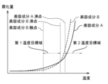
- FIG. 35 is a graph showing changes in the atomization amounts of cosmetic ingredients A and B with respect to temperature.
- a cosmetic component B is defined as a cosmetic component having a change in atomization amount with respect to temperature shown in FIG. 34 .
- the melting point of cosmetic ingredient B is higher than the melting point of cosmetic ingredient A.
- the boiling point of cosmetic ingredient A is higher than the boiling point of cosmetic ingredient B. Therefore, as shown in FIG.
- the first temperature target range for atomizing a small amount of cosmetic ingredient A and cosmetic ingredient B is set to a range above the melting point of cosmetic ingredient B and below its boiling point.
- the second temperature target range when a large amount of cosmetic ingredient A and cosmetic ingredient B are atomized is set at the boiling point of cosmetic ingredient A or higher.
- the control unit 9 controls the heating of the heater 51 based on the temperature measured by the thermocouple 53 in the first temperature target range, 39 temperature control.
- the controller 9 controls the temperature of the contactor 39 within the first temperature target range, the cosmetic ingredient A and the cosmetic ingredient B in the ingredient solid portion 33 become liquid, and the cosmetic ingredient A and the cosmetic ingredient B are atomized. Deformation of the component solid portion 33 can be minimized. In addition, the component solid portion 33 can be efficiently consumed, and the replacement frequency of the component solid portion 33 can be reduced.
- the control unit 9 sets a reference target temperature between the melting point and the boiling point of the cosmetic ingredient B, such as an intermediate temperature between the melting point and the boiling point of the cosmetic ingredient B, in the first temperature target range.
- the control unit 9 controls the temperature of the contactor 39 between the reference target temperature and the boiling point of the cosmetic ingredient B when increasing the atomization amount of the cosmetic ingredient A and the cosmetic ingredient B.
- FIG. The controller 9 adjusts the temperature of the contactor 39 between the reference target temperature and the melting point of the cosmetic ingredient B when reducing the atomization amounts of the cosmetic ingredient A and the cosmetic ingredient B.
- FIG. By setting the reference target temperature of the contactor 39 by the control unit 9 , the cosmetic component A and the cosmetic component B can be ejected from the ejection unit 13 in optimum atomization amounts.
- the control unit 9 controls heating of the heater 51 based on the temperature measured by the thermocouple 53 in the second temperature target range, Control the temperature.
- the controller 9 controls the temperature of the contactor 39 within the second temperature target range, the cosmetic component A and the cosmetic component B in the solid component portion 33 become gases, and the cosmetic component A and the cosmetic component B are gasified in the solid component portion 33. B does not drip.
- the contactor 39 has a temperature equal to or higher than the boiling point of the cosmetic component A, which is higher than the boiling point of the cosmetic component B, the cosmetic component A and the cosmetic component B can be atomized in a short time.
- control portion 9 similarly controls the first temperature target range, the reference target temperature, the second temperature A target area is set and similar control is performed.
- the component solid portion 33 when a plurality of types of cosmetic ingredients with different melting points are arranged in the component solid portion 33 as shown in FIGS. Low cosmetic ingredients are arranged on the outside.
- the cosmetic ingredient B since the cosmetic ingredient B has a higher melting point than the cosmetic ingredient A, the cosmetic ingredient B is arranged inside and the cosmetic ingredient A is arranged outside.
- the melting point of the cosmetic component C is higher than the melting points of the cosmetic component A and the cosmetic component B, and the cosmetic component C is arranged inside, and the cosmetic component B is arranged on the outside. is arranged, and the cosmetic ingredient A is arranged on the outer side thereof.
- the control section 9 operates the drive section 37 to bring the component solid section 33 and the contactor 39 into contact with each other to atomize only the cosmetic component A.
- the cosmetic component B on the center side remains. Therefore, it is possible to prevent the component solid portion 33 from becoming hollow, and to minimize the deformation of the component solid portion 33 .
- the deformation of the component solid portion 33 can be minimized because the amount of atomization of the cosmetic ingredient A is greater. can. Even in the component solid portion 33 containing three or more cosmetic components as shown in FIG. can be reduced to In the component solid portion 33 containing a plurality of types of cosmetic components, the deformation of the component solid portion 33 can be minimized by arranging the cosmetic component having a low melting point on the outside.
- the control unit 9 controls each mechanism.
- the control section 9 operates the driving portion 37 to rotate the component solid portion 33 so that the contactor 39 moves around the component solid portion 33 . Control to evenly touch the direction.
- the cosmetic component can be uniformly atomized in the circumferential direction of the component solid portion 33, and the component solid portion 33 can be consumed without waste. can.
- the replacement frequency of the component solid portion 33 can be reduced.
- the control unit 9 controls the operation of the driving unit 37, stops the rotation of the solid component part 33 at the same position, and changes the pressing force of the solid component part 33, thereby controlling the plurality of types of cosmetic ingredients. With the atomization ratio of , the atomization amount can be changed.
- the contactor 39 may be provided with a type detection section (not shown) for determining the type of cosmetic ingredient.
- the type detection unit is provided, for example, on the contact portion 49 of the contactor 39 and electrically connected to the control unit 9 .
- the kind detection unit inputs the kind of cosmetic ingredient contained in the ingredient solid portion 33 to the control unit 9 .
- the control unit 9 controls the operation of the drive unit 37 based on the type of cosmetic ingredient detected by the type detection unit, and controls the pressing force of the component solid portion 33 . Therefore, the pressing force of the component solid portion 33 can be controlled in accordance with the characteristics of the cosmetic component contained in the component solid portion 33, and different types of cosmetic components can be appropriately atomized.
- control unit 9 controls overheating of the heater 51 and controls the temperature of the contactor 39 based on the type of cosmetic ingredient detected by the type detection unit. Therefore, it is possible to control the temperature of the contactor 39 according to the melting point or boiling point (or sublimation point) of the cosmetic ingredients contained in the component solid portion 33, and appropriately atomize different types of cosmetic ingredients. can be made Note that the control unit 9 simultaneously controls the pressing force of the component solid portion 33 and the temperature of the contactor 39 based on the type of cosmetic ingredient detected by the type detection unit.
- FIG. 36 is a cross-sectional view of the cosmetic ingredient spraying device according to this embodiment when it is equipped with an atomization amount detection unit.
- the cosmetic ingredient spraying device 1 may include an atomization amount detector 57 for measuring the atomization amount of the atomized cosmetic ingredient.
- the atomization amount detection unit 57 is arranged, for example, in the vicinity of the component ejection port 17 of the ejection unit 13 .
- the atomization amount detector 57 is electrically connected to the controller 9 .
- the atomization amount detection unit 57 measures the atomization amount of the atomized cosmetic ingredients contained in the air flow ejected from the ejection unit 13 and inputs the amount to the control unit 9 .
- the control unit 9 controls the operation of the driving unit 37 to control the pressing force of the component solid portion 33, and also controls the heating of the heater 51 to achieve contact. control the temperature of the child 39;
- the control unit 9 controls the operation of the drive unit 37 and the temperature of the contactor 39 based on the atomization amount measured by the atomization amount detection unit 57 , so that the optimum amount of atomization of the cosmetic component is supplied from the ejection unit 13 . can be ejected.
- there is no need to set a predicted target atomization amount and the control unit 9 can accurately control the contactor 39 and the drive unit 37 in accordance with the atomization amount.
- Such a cosmetic ingredient spraying device 1 includes an ingredient solid portion 33 containing at least one cosmetic ingredient that is solid or quasi-solid at room temperature, and a heatable contactor 39 . Further, a driving portion 37 connected to one of the component solid portion 33 and the contactor 39 and moving the other with respect to the other, and electrically connected to the contactor 39 and the driving portion 37, and the contactor 39 and a control unit 9 for controlling the temperature of and the operation of the drive unit 37 . Then, the controller 9 raises the temperature of the contactor 39 to the melting point or sublimation point of the cosmetic ingredient or higher, operates the driving section 37, and keeps the ingredient solid portion 33 and the contactor 39 in continuous contact. The state of contact between the portion 33 and the contactor 39 is changed to atomize the cosmetic ingredients.
- the control unit 9 brings the component solid portion 33 containing the cosmetic component solid or semi-solid at room temperature into contact with the contactor 39 heated to the melting point or sublimation point of the cosmetic component to atomize the cosmetic component. . Therefore, until the cosmetic ingredient in the component solid portion 33 is completely atomized, the atomized amount of the cosmetic ingredient does not fluctuate, and the sprayed amount of the cosmetic ingredient can be stabilized.
- control unit 9 atomizes the cosmetic ingredients while keeping the component solid portion 33 and the contactor 39 in continuous contact. Therefore, the cosmetic ingredients are continuously atomized without interruption. Furthermore, the control unit 9 changes the contact state between the component solid portion 33 and the contactor 39 to atomize the cosmetic component. Therefore, by changing the contact state between the component solid portion 33 and the contactor 39, the atomization amount of the cosmetic component can be adjusted.
- the control section 9 operates the driving section 37 so as to increase the pressing force between the solid ingredient portion 33 and the contactor 39 . Further, when the amount of atomized cosmetic ingredients is to be reduced, the control section 9 operates the driving section 37 so as to reduce the pressing force between the solid component portion 33 and the contactor 39 . Therefore, by controlling the pressing force between the component solid portion 33 and the contactor 39 by the control section 9, the atomization amount of the cosmetic component can be adjusted.
- An elastic member 41 is in contact with the other of the component solid portion 33 and the contactor 39 and receives a pressing force from one of the component solid portion 33 and the contactor 39 when the component solid portion 33 and the contactor 39 come into contact with each other. there is Therefore, it is possible to suppress variation in the contact pressure between the component solid portion 33 and the contactor 39 and suppress variation in the atomization amount of the cosmetic component.
- the cosmetic ingredient spraying device 1 also includes a force detection section 55 electrically connected to the control section 9 for measuring the pressing force when the solid ingredient portion 33 and the contactor 39 come into contact with each other. Then, the control section 9 operates the driving section 37 based on the pressing force measured by the force detecting section 55 to change the contact state between the component solid section 33 and the contactor 39 . Therefore, the control unit 9 controls the operation of the driving unit 37 based on the pressing force measured by the force detection unit 55, so that an optimum pressing force can be obtained in accordance with the atomization amount.
- the control portion 9 operates the driving portion 37 so as to change the state of contact between the solid component portion 33 and the contactor 39, The temperature of the contactor 39 is changed. Therefore, a predetermined amount of cosmetic ingredients can be atomized, and the atomized amount of cosmetic ingredients can be stabilized.
- control unit 9 preheats the contactor 39 when the component solid portion 33 and the contactor 39 are separated from each other. Therefore, when the component solid portion 33 and the contactor 39 come into contact with each other, the cosmetic component is immediately atomized, and the atomization speed of the cosmetic component can be improved.
- control unit 9 sets the reference target temperature of the contactor 39 between the melting point and the boiling point of the cosmetic ingredient.
- the control unit 9 controls the temperature of the contactor 39 to be equal to or higher than the reference target temperature and equal to or lower than the boiling point of the cosmetic ingredient.
- the control unit 9 controls the temperature of the contactor 39 to be equal to or lower than the reference target temperature and equal to or higher than the melting point of the cosmetic ingredient. Therefore, by setting the reference target temperature of the contactor 39 between the melting point and the boiling point of the cosmetic ingredient by the controller 9, deformation of the ingredient solid portion 33 due to atomization of the cosmetic ingredient can be minimized. .
- the component solid portion 33 can be efficiently consumed, and the replacement frequency of the component solid portion 33 can be reduced. Furthermore, an optimum amount of cosmetic ingredients can be atomized.
- the control section 9 increases the pressing force between the component solid portion 33 and the contactor when increasing the atomization amount of the cosmetic ingredient. 37 is activated. Further, when the reference target temperature of the contactor 39 is set, the control section 9 controls the drive so as to reduce the pressing force between the component solid portion 33 and the contactor 39 when decreasing the atomization amount of the cosmetic ingredient. Activating part 37 . Therefore, by simultaneously controlling the temperature of the contactor 39 and the pressing force between the component solid portion 33 and the contactor 39, the optimum amount of the cosmetic component can be atomized.
- control unit 9 keeps the temperature of the contactor 39 above the boiling point of the cosmetic ingredient, and operates the drive section 37 so that the pressing force between the component solid portion 33 and the contactor 39 continues to act. Therefore, the atomization speed of the cosmetic component can be improved, and the atomized amount of the cosmetic component can be continuously increased. In addition, the cosmetic ingredient becomes a gas, and the cosmetic ingredient does not drip in the ingredient solid portion 33 .
- the ingredient solid portion 33 contains a plurality of types of beauty ingredients. Therefore, one ingredient solid portion 33 can atomize a plurality of types of cosmetic ingredients.
- the cosmetic ingredient spraying device 1 also includes an atomization amount detection section 57 that measures the atomization amount of the atomized beauty ingredient and is electrically connected to the control section 9 . Then, the control unit 9 controls the temperature of the contactor 39 and the operation of the driving unit 37 based on the atomization amount measured by the atomization amount detection unit 57 . Therefore, an optimum amount of cosmetic ingredients can be atomized. In addition, the control unit 9 can accurately control the temperature of the contactor 39 and the operation of the driving unit 37 in accordance with the atomization amount of the cosmetic ingredient.
- the cosmetic ingredient spraying device 1 also includes an air blower 5 electrically connected to the controller 9 for applying hot air and normal temperature air to the atomized cosmetic ingredient via the contactor 39 .
- the controller 9 blows hot air from the air blower 5 when raising the temperature of the contactor 39, and blows normal temperature air from the air blower 5 when lowering the temperature of the contactor 39. - ⁇ Therefore, the temperature change of the contactor 39 can be assisted by the air blower 5, and the response speed to the change in the atomization amount of the cosmetic component can be improved.
- the driving section is connected to the component solid section, but the present invention is not limited to this, and the driving section may be connected to the contactor.
- the present invention is not limited to this, and a cover or the like that covers the component solid portion may be arranged around the component solid portion. By covering the periphery of the component solid portion, it is possible to suppress breakage of the component solid portion at the time of dropping or the like.
- the present disclosure is applicable to a cosmetic ingredient spraying device that sprays atomized cosmetic ingredients. Specifically, the present disclosure is applicable to hair dryers, straight irons, curling irons, facial equipment, scalp care devices, nail care devices, and the like.
Landscapes
- Devices For Medical Bathing And Washing (AREA)
- Massaging Devices (AREA)
- Cosmetics (AREA)
Priority Applications (4)
| Application Number | Priority Date | Filing Date | Title |
|---|---|---|---|
| US18/725,865 US20250073738A1 (en) | 2022-02-01 | 2022-11-30 | Beauty component atomizer |
| EP22924971.9A EP4473867A4 (en) | 2022-02-01 | 2022-11-30 | Beauty component atomizer |
| CN202280089503.3A CN118574542A (zh) | 2022-02-01 | 2022-11-30 | 美容成分喷雾装置 |
| JP2023578393A JPWO2023149066A1 (https=) | 2022-02-01 | 2022-11-30 |
Applications Claiming Priority (2)
| Application Number | Priority Date | Filing Date | Title |
|---|---|---|---|
| JP2022014223 | 2022-02-01 | ||
| JP2022-014223 | 2022-02-01 |
Publications (1)
| Publication Number | Publication Date |
|---|---|
| WO2023149066A1 true WO2023149066A1 (ja) | 2023-08-10 |
Family
ID=87552166
Family Applications (1)
| Application Number | Title | Priority Date | Filing Date |
|---|---|---|---|
| PCT/JP2022/044282 Ceased WO2023149066A1 (ja) | 2022-02-01 | 2022-11-30 | 美容成分噴霧装置 |
Country Status (5)
| Country | Link |
|---|---|
| US (1) | US20250073738A1 (https=) |
| EP (1) | EP4473867A4 (https=) |
| JP (1) | JPWO2023149066A1 (https=) |
| CN (1) | CN118574542A (https=) |
| WO (1) | WO2023149066A1 (https=) |
Citations (3)
| Publication number | Priority date | Publication date | Assignee | Title |
|---|---|---|---|---|
| JP2014534028A (ja) * | 2011-11-02 | 2014-12-18 | ロレアル | 化粧製品塗布要素およびそのような要素を備える包装塗布セット |
| JP2019111158A (ja) | 2017-12-25 | 2019-07-11 | テスコム電機株式会社 | ヘアドライヤーおよびヘアドライヤーに装着されるカートリッジ |
| JP2021133262A (ja) * | 2020-02-21 | 2021-09-13 | パナソニックIpマネジメント株式会社 | 美容成分噴霧装置 |
Family Cites Families (3)
| Publication number | Priority date | Publication date | Assignee | Title |
|---|---|---|---|---|
| JP7411896B2 (ja) * | 2020-02-21 | 2024-01-12 | パナソニックIpマネジメント株式会社 | 美容成分噴霧装置 |
| US20240268539A1 (en) * | 2021-07-13 | 2024-08-15 | Panasonic Intellectual Property Management Co., Ltd. | Cosmetic material and hairdressing appliance |
| JP2023050386A (ja) * | 2021-09-30 | 2023-04-11 | パナソニックIpマネジメント株式会社 | 理美容機器 |
-
2022
- 2022-11-30 US US18/725,865 patent/US20250073738A1/en active Pending
- 2022-11-30 JP JP2023578393A patent/JPWO2023149066A1/ja active Pending
- 2022-11-30 CN CN202280089503.3A patent/CN118574542A/zh active Pending
- 2022-11-30 EP EP22924971.9A patent/EP4473867A4/en active Pending
- 2022-11-30 WO PCT/JP2022/044282 patent/WO2023149066A1/ja not_active Ceased
Patent Citations (3)
| Publication number | Priority date | Publication date | Assignee | Title |
|---|---|---|---|---|
| JP2014534028A (ja) * | 2011-11-02 | 2014-12-18 | ロレアル | 化粧製品塗布要素およびそのような要素を備える包装塗布セット |
| JP2019111158A (ja) | 2017-12-25 | 2019-07-11 | テスコム電機株式会社 | ヘアドライヤーおよびヘアドライヤーに装着されるカートリッジ |
| JP2021133262A (ja) * | 2020-02-21 | 2021-09-13 | パナソニックIpマネジメント株式会社 | 美容成分噴霧装置 |
Non-Patent Citations (1)
| Title |
|---|
| See also references of EP4473867A4 |
Also Published As
| Publication number | Publication date |
|---|---|
| EP4473867A4 (en) | 2025-05-28 |
| CN118574542A (zh) | 2024-08-30 |
| EP4473867A1 (en) | 2024-12-11 |
| US20250073738A1 (en) | 2025-03-06 |
| JPWO2023149066A1 (https=) | 2023-08-10 |
Similar Documents
| Publication | Publication Date | Title |
|---|---|---|
| US9326582B2 (en) | Heating application device for a cosmetic product | |
| US20110133001A1 (en) | Hand held skin treatment spray system | |
| AU2010325819A1 (en) | Hand held skin treatment spray system with proportional air and liquid control | |
| US20090020133A1 (en) | Kit for making up the eyelashes, including an applicator device with a heater | |
| EP3133956B1 (en) | Product application device | |
| WO2008081764A1 (en) | Electrostatic atomizer | |
| JP2019098638A (ja) | 媒体処理装置及び媒体処理装置の制御方法 | |
| JP5439368B2 (ja) | 一定の整形用空気温度を有する塗装装置、ならびに塗装方法 | |
| WO2023149066A1 (ja) | 美容成分噴霧装置 | |
| CN118512046A (zh) | 电源组件、雾化器及控制方法、电子雾化装置及存储介质 | |
| WO2023053824A1 (ja) | 理美容機器 | |
| EP4108129B1 (en) | Haircare device | |
| WO2023286467A1 (ja) | 化粧料及び理美容機器 | |
| KR200190834Y1 (ko) | 미용용 모발처리기 | |
| KR101745348B1 (ko) | 꿀 분말을 제조하기 위한 분무건조장치 | |
| US20130330285A1 (en) | Heated spray system for applying tanning solution | |
| EP4108128B1 (en) | Beauty component nebulizer | |
| EP4108125B1 (en) | Cosmetic ingredient spraying device | |
| JP2014008990A (ja) | 油性化粧料の充填ノズル | |
| JPWO2023149066A5 (https=) | ||
| JP2023012405A (ja) | 化粧料及び理美容機器 | |
| US20170050203A1 (en) | Nebulizer | |
| JPH10215751A (ja) | 殺虫剤煙霧機 | |
| CN117597101A (zh) | 化妆品和美容美发设备 | |
| CN214747076U (zh) | 一种麦芽糖粉喷雾干燥装置 |
Legal Events
| Date | Code | Title | Description |
|---|---|---|---|
| 121 | Ep: the epo has been informed by wipo that ep was designated in this application |
Ref document number: 22924971 Country of ref document: EP Kind code of ref document: A1 |
|
| WWE | Wipo information: entry into national phase |
Ref document number: 2023578393 Country of ref document: JP |
|
| WWE | Wipo information: entry into national phase |
Ref document number: 18725865 Country of ref document: US |
|
| WWE | Wipo information: entry into national phase |
Ref document number: 202280089503.3 Country of ref document: CN |
|
| WWE | Wipo information: entry into national phase |
Ref document number: 2022924971 Country of ref document: EP |
|
| NENP | Non-entry into the national phase |
Ref country code: DE |
|
| ENP | Entry into the national phase |
Ref document number: 2022924971 Country of ref document: EP Effective date: 20240902 |
|
| WWP | Wipo information: published in national office |
Ref document number: 18725865 Country of ref document: US |