WO2023145707A1 - 緩衝器 - Google Patents
緩衝器 Download PDFInfo
- Publication number
- WO2023145707A1 WO2023145707A1 PCT/JP2023/002006 JP2023002006W WO2023145707A1 WO 2023145707 A1 WO2023145707 A1 WO 2023145707A1 JP 2023002006 W JP2023002006 W JP 2023002006W WO 2023145707 A1 WO2023145707 A1 WO 2023145707A1
- Authority
- WO
- WIPO (PCT)
- Prior art keywords
- cylinder
- shock absorber
- peripheral surface
- outer peripheral
- diameter
- Prior art date
- Legal status (The legal status is an assumption and is not a legal conclusion. Google has not performed a legal analysis and makes no representation as to the accuracy of the status listed.)
- Ceased
Links
Images







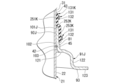
Classifications
-
- B—PERFORMING OPERATIONS; TRANSPORTING
- B60—VEHICLES IN GENERAL
- B60G—VEHICLE SUSPENSION ARRANGEMENTS
- B60G15/00—Resilient suspensions characterised by arrangement, location or type of combined spring and vibration damper, e.g. telescopic type
- B60G15/02—Resilient suspensions characterised by arrangement, location or type of combined spring and vibration damper, e.g. telescopic type having mechanical spring
- B60G15/06—Resilient suspensions characterised by arrangement, location or type of combined spring and vibration damper, e.g. telescopic type having mechanical spring and fluid damper
- B60G15/062—Resilient suspensions characterised by arrangement, location or type of combined spring and vibration damper, e.g. telescopic type having mechanical spring and fluid damper the spring being arranged around the damper
- B60G15/063—Resilient suspensions characterised by arrangement, location or type of combined spring and vibration damper, e.g. telescopic type having mechanical spring and fluid damper the spring being arranged around the damper characterised by the mounting of the spring on the damper
-
- F—MECHANICAL ENGINEERING; LIGHTING; HEATING; WEAPONS; BLASTING
- F16—ENGINEERING ELEMENTS AND UNITS; GENERAL MEASURES FOR PRODUCING AND MAINTAINING EFFECTIVE FUNCTIONING OF MACHINES OR INSTALLATIONS; THERMAL INSULATION IN GENERAL
- F16F—SPRINGS; SHOCK-ABSORBERS; MEANS FOR DAMPING VIBRATION
- F16F9/00—Springs, vibration-dampers, shock-absorbers, or similarly-constructed movement-dampers using a fluid or the equivalent as damping medium
- F16F9/32—Details
-
- F—MECHANICAL ENGINEERING; LIGHTING; HEATING; WEAPONS; BLASTING
- F16—ENGINEERING ELEMENTS AND UNITS; GENERAL MEASURES FOR PRODUCING AND MAINTAINING EFFECTIVE FUNCTIONING OF MACHINES OR INSTALLATIONS; THERMAL INSULATION IN GENERAL
- F16F—SPRINGS; SHOCK-ABSORBERS; MEANS FOR DAMPING VIBRATION
- F16F13/00—Units comprising springs of the non-fluid type as well as vibration-dampers, shock-absorbers, or fluid springs
- F16F13/005—Units comprising springs of the non-fluid type as well as vibration-dampers, shock-absorbers, or fluid springs comprising both a wound spring and a damper, e.g. a friction damper
- F16F13/007—Units comprising springs of the non-fluid type as well as vibration-dampers, shock-absorbers, or fluid springs comprising both a wound spring and a damper, e.g. a friction damper the damper being a fluid damper
-
- F—MECHANICAL ENGINEERING; LIGHTING; HEATING; WEAPONS; BLASTING
- F16—ENGINEERING ELEMENTS AND UNITS; GENERAL MEASURES FOR PRODUCING AND MAINTAINING EFFECTIVE FUNCTIONING OF MACHINES OR INSTALLATIONS; THERMAL INSULATION IN GENERAL
- F16F—SPRINGS; SHOCK-ABSORBERS; MEANS FOR DAMPING VIBRATION
- F16F9/00—Springs, vibration-dampers, shock-absorbers, or similarly-constructed movement-dampers using a fluid or the equivalent as damping medium
- F16F9/32—Details
- F16F9/3207—Constructional features
-
- F—MECHANICAL ENGINEERING; LIGHTING; HEATING; WEAPONS; BLASTING
- F16—ENGINEERING ELEMENTS AND UNITS; GENERAL MEASURES FOR PRODUCING AND MAINTAINING EFFECTIVE FUNCTIONING OF MACHINES OR INSTALLATIONS; THERMAL INSULATION IN GENERAL
- F16F—SPRINGS; SHOCK-ABSORBERS; MEANS FOR DAMPING VIBRATION
- F16F9/00—Springs, vibration-dampers, shock-absorbers, or similarly-constructed movement-dampers using a fluid or the equivalent as damping medium
- F16F9/32—Details
- F16F9/38—Covers for protection or appearance
-
- F—MECHANICAL ENGINEERING; LIGHTING; HEATING; WEAPONS; BLASTING
- F16—ENGINEERING ELEMENTS AND UNITS; GENERAL MEASURES FOR PRODUCING AND MAINTAINING EFFECTIVE FUNCTIONING OF MACHINES OR INSTALLATIONS; THERMAL INSULATION IN GENERAL
- F16F—SPRINGS; SHOCK-ABSORBERS; MEANS FOR DAMPING VIBRATION
- F16F9/00—Springs, vibration-dampers, shock-absorbers, or similarly-constructed movement-dampers using a fluid or the equivalent as damping medium
- F16F9/32—Details
- F16F9/58—Stroke limiting stops, e.g. arranged on the piston rod outside the cylinder
-
- B—PERFORMING OPERATIONS; TRANSPORTING
- B60—VEHICLES IN GENERAL
- B60G—VEHICLE SUSPENSION ARRANGEMENTS
- B60G2202/00—Indexing codes relating to the type of spring, damper or actuator
- B60G2202/30—Spring/Damper and/or actuator Units
- B60G2202/31—Spring/Damper and/or actuator Units with the spring arranged around the damper, e.g. MacPherson strut
- B60G2202/312—The spring being a wound spring
-
- B—PERFORMING OPERATIONS; TRANSPORTING
- B60—VEHICLES IN GENERAL
- B60G—VEHICLE SUSPENSION ARRANGEMENTS
- B60G2204/00—Indexing codes related to suspensions per se or to auxiliary parts
- B60G2204/10—Mounting of suspension elements
- B60G2204/12—Mounting of springs or dampers
- B60G2204/124—Mounting of coil springs
- B60G2204/1242—Mounting of coil springs on a damper, e.g. MacPerson strut
-
- B—PERFORMING OPERATIONS; TRANSPORTING
- B60—VEHICLES IN GENERAL
- B60G—VEHICLE SUSPENSION ARRANGEMENTS
- B60G2206/00—Indexing codes related to the manufacturing of suspensions: constructional features, the materials used, procedures or tools
- B60G2206/01—Constructional features of suspension elements, e.g. arms, dampers, springs
- B60G2206/40—Constructional features of dampers and/or springs
- B60G2206/41—Dampers
-
- B—PERFORMING OPERATIONS; TRANSPORTING
- B60—VEHICLES IN GENERAL
- B60G—VEHICLE SUSPENSION ARRANGEMENTS
- B60G2206/00—Indexing codes related to the manufacturing of suspensions: constructional features, the materials used, procedures or tools
- B60G2206/01—Constructional features of suspension elements, e.g. arms, dampers, springs
- B60G2206/70—Materials used in suspensions
- B60G2206/73—Rubber; Elastomers
-
- B—PERFORMING OPERATIONS; TRANSPORTING
- B60—VEHICLES IN GENERAL
- B60G—VEHICLE SUSPENSION ARRANGEMENTS
- B60G2800/00—Indexing codes relating to the type of movement or to the condition of the vehicle and to the end result to be achieved by the control action
- B60G2800/16—Running
- B60G2800/162—Reducing road induced vibrations
-
- F—MECHANICAL ENGINEERING; LIGHTING; HEATING; WEAPONS; BLASTING
- F16—ENGINEERING ELEMENTS AND UNITS; GENERAL MEASURES FOR PRODUCING AND MAINTAINING EFFECTIVE FUNCTIONING OF MACHINES OR INSTALLATIONS; THERMAL INSULATION IN GENERAL
- F16F—SPRINGS; SHOCK-ABSORBERS; MEANS FOR DAMPING VIBRATION
- F16F2224/00—Materials; Material properties
- F16F2224/02—Materials; Material properties solids
- F16F2224/025—Elastomers
-
- F—MECHANICAL ENGINEERING; LIGHTING; HEATING; WEAPONS; BLASTING
- F16—ENGINEERING ELEMENTS AND UNITS; GENERAL MEASURES FOR PRODUCING AND MAINTAINING EFFECTIVE FUNCTIONING OF MACHINES OR INSTALLATIONS; THERMAL INSULATION IN GENERAL
- F16F—SPRINGS; SHOCK-ABSORBERS; MEANS FOR DAMPING VIBRATION
- F16F2232/00—Nature of movement
- F16F2232/08—Linear
-
- F—MECHANICAL ENGINEERING; LIGHTING; HEATING; WEAPONS; BLASTING
- F16—ENGINEERING ELEMENTS AND UNITS; GENERAL MEASURES FOR PRODUCING AND MAINTAINING EFFECTIVE FUNCTIONING OF MACHINES OR INSTALLATIONS; THERMAL INSULATION IN GENERAL
- F16F—SPRINGS; SHOCK-ABSORBERS; MEANS FOR DAMPING VIBRATION
- F16F2234/00—Shape
- F16F2234/02—Shape cylindrical
Definitions
- the present invention relates to shock absorbers.
- This application claims priority based on Japanese Patent Application No. 2022-011408 filed in Japan on January 28, 2022, the content of which is incorporated herein.
- shock absorber with a structure in which an annular groove is formed in the outer circumference of the cylinder, a substantially C-shaped locking ring is fitted in the annular groove, and the spring seat is supported on the cylinder by the locking ring (see, for example, patent Reference 1).
- An object of the present invention is to provide a shock absorber capable of suppressing relative movement between a cylinder and a spring receiving member.
- a damper in order to achieve the above object, includes a cylinder, a piston slidably provided in the cylinder, and a piston rod connected to the piston.
- a first movement suppressing portion that is provided in a cylindrical portion of the cylinder and protrudes radially outward; a cylindrical cylindrical portion that covers at least a portion of the cylinder; a seating portion on which a suspension spring is seated; a spring bearing member that abuts against the first movement suppressing portion to suppress axial movement of the cylinder; and a second movement suppressing portion that suppresses relative movement with respect to the member in the circumferential direction.
- a shock absorber is a shock absorber comprising a cylinder, a piston slidably provided in the cylinder, and a piston rod connected to the piston, wherein the outer circumference of the cylinder a spring receiving member disposed on the surface side and having a cylindrical tubular portion covering at least a portion of the cylinder; and a seating portion on which a suspension spring is seated; a first movement suppressing portion that suppresses movement in the axial direction; a communication portion that is provided in the cylindrical portion and communicates between the outer peripheral surface side of the cylinder and the outer peripheral surface side of the cylindrical portion; and at least a portion of the inner peripheral surface. is in contact with the outer peripheral surface of the cylindrical portion and the outer peripheral surface of the cylinder, and includes a second movement suppressing portion having a surface facing the cylindrical portion and a surface facing the cylinder.
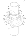
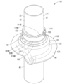
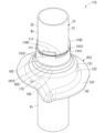
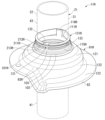
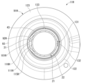
- FIG. 21 is a partial perspective view showing a part of a shock absorber of an eighth embodiment according to the present invention. It is a partial perspective view which shows the principal part of the shock absorber of 9th Embodiment which concerns on this invention. It is a sectional view showing an important section of a shock absorber of a ninth embodiment concerning the present invention.
- FIG. 20 is a partial perspective view showing the essential parts of the shock absorber of the tenth embodiment according to the present invention; FIG.
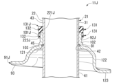
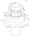
- FIG. 20 is a cross-sectional view showing the main part of the shock absorber of the tenth embodiment according to the present invention. It is a partial perspective view which shows the principal part of the shock absorber of 11th Embodiment which concerns on this invention.
- FIG. 20 is a cross-sectional view showing the essential parts of the shock absorber of the eleventh embodiment according to the present invention.
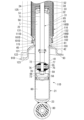
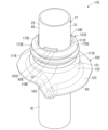
- FIG. A shock absorber 11 shown in FIG. 1 is a shock absorber used in a suspension device of a vehicle such as an automobile or a railroad vehicle.
- the shock absorber 11 is specifically a shock absorber used in an automobile suspension system.
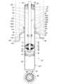
- the buffer 11 has a cylinder 21 .
- the shock absorber 11 is a monotube type shock absorber having a single cylinder 21, a so-called monotube type shock absorber.
- the cylinder 21 has a tubular shape, specifically a bottomed tubular shape.
- the cylinder 21 has a body portion 22 and a bottom portion 23 .
- the barrel 22 is cylindrical.
- the bottom portion 23 is disc-shaped and closes one axial end portion of the body portion 22 .
- the other end portion of the body portion 22 opposite to the bottom portion 23 is an opening 24 .
- the cylinder 21 is an integrally molded product made of one member made of metal.
- the trunk portion 22 includes, in the axial direction, a first cylindrical portion 31 (cylindrical portion), an intermediate locking portion 32, a second cylindrical portion 33, and an end locking portion 34 in this order from the bottom portion 23 side. have.
- the first cylindrical portion 31 has a cylindrical shape over the entire length in the axial direction. and have
- the first large-diameter portion 41 has a radially outer peripheral surface that is cylindrical, and a radially inner peripheral surface that is coaxial with the outer peripheral surface.
- the small-diameter portion 42 has a cylindrical outer peripheral surface on the radially outer side, and an inner peripheral surface on the radially inner side of the small-diameter portion 42 that is coaxial with the outer peripheral surface.
- the small diameter portion 42 has an inner diameter equal to that of the first large diameter portion 41 and an outer diameter smaller than that of the first large diameter portion 41 .
- the second large-diameter portion 43 has a radially outer peripheral surface that is cylindrical, and a radially inner peripheral surface that is coaxial with the outer peripheral surface.
- the second large diameter portion 43 has an outer diameter equal to that of the first large diameter portion 41 and an inner diameter equal to that of the first large diameter portion 41 .
- the first large-diameter portion 41 , the small-diameter portion 42 , and the second large-diameter portion 43 share a central axis, and this central axis is the central axis of the first cylindrical portion 31 .
- the first cylindrical portion 31 has a fitting groove 45 on the outer diameter side of the small diameter portion 42 between the first large diameter portion 41 and the second large diameter portion 43 in the axial direction.
- the fitting groove 45 is recessed radially inward from the outer peripheral surface of the first large diameter portion 41 and the outer peripheral surface of the second large diameter portion 43 .
- the fitting groove 45 is annular.
- the second cylindrical portion 33 has a cylindrical shape over its entire length in the axial direction.
- the second cylindrical portion 33 has a radially outer peripheral surface that is cylindrical, and a radially inner peripheral surface that is coaxial with the outer peripheral surface.
- the second cylindrical portion 33 has an outer diameter equal to the outer diameter of the first large diameter portion 41 and the second large diameter portion 43, and an inner diameter of the first large diameter portion 41 and the second large diameter portion 43. is equivalent to
- the second cylindrical portion 33 and the first cylindrical portion 31 have a common central axis.
- the intermediate locking portion 32 is recessed radially inward from the outer peripheral surface of the second cylindrical portion 33 and the outer peripheral surface of the second large diameter portion 43 .
- the intermediate locking portion 32 protrudes radially inward from the inner peripheral surface of the second cylindrical portion 33 and the inner peripheral surface of the second large diameter portion 43 .
- the intermediate locking portion 32 has an annular shape.
- the end engaging portion 34 protrudes radially inward of the second cylindrical portion 33 from the inner peripheral surface of the second cylindrical portion 33 .
- the end locking portion 34 is annular.
- the opening 24 is formed inside the end engaging portion 34 in the radial direction.
- the body portion 22 has a cylindrical shape with a constant inner diameter over the entire length in the axial direction and a constant outer diameter over the entire length in the axial direction.
- the shock absorber 11 is provided with a rod guide 51.
- the rod guide 51 has an annular shape and is fitted to the second cylindrical portion 33 of the cylinder 21 .
- the bottom portion 23 side of the rod guide 51 in the axial direction is in contact with the intermediate locking portion 32 .
- the buffer 11 has a seal member 52 .
- the seal member 52 has an annular shape and is provided closer to the opening 24 of the cylinder 21 than the rod guide 51 is.
- the seal member 52 is also fitted to the second cylindrical portion 33 of the cylinder 21 in the same manner as the rod guide 51 .
- the seal member 52 is sandwiched between the end locking portion 34 and the rod guide 51 in the axial direction of the cylinder 21 .
- the seal member 52 closes the opening 24 of the cylinder 21 .
- the damper 11 has a piston 55 and a free piston 56 . Both the piston 55 and the free piston 56 are slidably provided within the first cylindrical portion 31 of the cylinder 21 .
- the piston 55 is closer to the opening 24 than the free piston 56 in the axial direction of the cylinder 21 .
- the piston 55 defines two chambers, a first chamber 58 and a second chamber 59 within the cylinder 21 .
- the free piston 56 defines two chambers, a second chamber 59 and a gas chamber 60 within the cylinder 21 .
- the first chamber 58 is a portion between the piston 55 and the rod guide 51 inside the cylinder 21 .
- the second chamber 59 is a portion between the piston 55 and the free piston 56 inside the cylinder 21 .
- the gas chamber 60 is the portion between the free piston 56 and the bottom 23 inside the cylinder 21 .
- the first chamber 58 and the second chamber 59 are filled with oil liquid L as working fluid.
- the gas chamber 60 is filled with gas G as a working fluid.
- the shock absorber 11 includes a piston rod 65 and a nut 66.
- the piston rod 65 is inserted into the body portion 22 of the cylinder 21 and connected to the piston 55 at one end in the axial direction.
- the piston rod 65 extends from the cylinder 21 to the outside through the opening 24 on the opposite side of the piston 55 in the axial direction.
- a piston 55 is connected to the piston rod 65 by a nut 66 .
- the piston rod 65 is made of metal and has a main shaft portion 71 and a mounting shaft portion 72 .
- the main shaft portion 71 is cylindrical.
- the outer peripheral surface of the main shaft portion 71 is a cylindrical surface.
- the mounting shaft portion 72 has a cylindrical shape and an outer diameter smaller than that of the main shaft portion 71 .
- a male thread 73 is formed on the outer peripheral portion of the mounting shaft portion 72 on the side opposite to the main shaft portion 71 in the axial direction.
- the piston 55 is fitted on the mounting shaft portion 72 .
- the nut 66 is screwed onto the male screw 73 of the mounting shaft portion 72 .
- the piston rod 65 extends outside from the cylinder 21 through the rod guide 51 and the seal member 52 at the main shaft portion 71 .
- the main shaft portion 71 of the piston rod 65 is inserted into the rod guide 51 and the seal member 52 .
- the main shaft portion 71 of the piston rod 65 is in sliding contact with the rod guide 51 on the outer peripheral surface.
- the piston rod 65 is guided by the rod guide 51 and moves axially together with the piston 55 relative to the cylinder 21 .
- the main shaft portion 71 of the piston rod 65 is in sliding contact with the seal member 52 on the outer peripheral surface.
- the seal member 52 seals between the second cylindrical portion 33 of the cylinder 21 and the piston rod 65 .
- the seal member 52 prevents the oil L in the cylinder 21 from leaking to the outside.
- a passage 75 and a passage 76 are formed in the piston 55 .
- the passages 75 and 76 penetrate the piston 55 in the axial direction of the piston 55 .
- the passages 75 and 76 can communicate the first chamber 58 and the second chamber 59 .
- the buffer 11 has a disk valve 77 .
- the disc valve 77 is provided on the opposite side of the bottom portion 23 in the axial direction of the piston 55 .
- the disk valve 77 has an annular shape and closes the passage 75 by contacting the piston 55 .
- the damper 11 has a disc valve 78 .
- the disc valve 78 is provided on the bottom portion 23 side in the axial direction of the piston 55 .
- the disc valve 78 has an annular shape and closes the passage 76 by contacting the piston 55 .
- the direction in which the piston rod 65 increases the amount of entry into the cylinder 21 is the contraction side.
- the piston 55 moves in the direction to narrow the second chamber 59 .
- the disc valve 77 opens the passage 75 to allow the oil L in the second chamber 59 to flow through the passage 75 into the first chamber. It will flow to 58. At that time, the disc valve 77 generates a damping force.
- the direction in which the piston rod 65 protrudes from the cylinder 21 is the extension side.
- the piston 55 moves in the direction to narrow the first chamber 58 .
- the disk valve 78 opens the passage 76 to allow the oil L in the first chamber 58 to flow through the passage 76 into the second chamber. It will flow to 59. At that time, the disc valve 78 generates a damping force.
- a fixed orifice (not shown) is formed in at least one of the piston 55 and the disc valve 77 .
- This fixed orifice allows the first chamber 58 and the second chamber 59 to communicate with each other through the passage 75 even when the disk valve 77 closes the passage 75 to the maximum.
- At least one of the piston 55 and the disk valve 78 is formed with a fixed orifice (not shown). This fixed orifice allows communication between the first chamber 58 and the second chamber 59 through the passage 76 even when the disc valve 78 blocks the passage 76 to the maximum.
- the free piston 56 moves in the axial direction with respect to the cylinder 21 according to changes in the amount of entry of the piston rod 65 into the first chamber 58 . That is, when the piston rod 65 increases the amount of entry into the first chamber 58, the free piston 56 moves toward the bottom 23 according to its volume, and the piston rod 65 increases the amount of entry into the first chamber 58. When reduced, it moves away from the bottom 23 according to its volume.
- the shock absorber 11 has a mounting eye 80 that is fixed by welding to the outer surface of the bottom portion 23 on the side opposite to the body portion 22 in the axial direction.
- the shock absorber 11 has the piston rod 65 arranged at the upper portion thereof and is connected to the vehicle body side of the vehicle, and the mounting eye 80 is arranged at the lower portion thereof and is connected to the wheel side of the vehicle. Therefore, the damper 11 generates a damping force against the movement of the wheels with respect to the vehicle body.
- the attachment eye 80 is attached to the wheel-side attachment portion at a specified position in the circumferential direction of the cylinder 21 .
- the shock absorber 11 includes a contact ring 81 (first movement suppressing portion).
- the contact ring 81 is made of metal and is a C-shaped C ring formed by dividing a circular ring at one point in the circumferential direction.
- the contact ring 81 has a radially outer peripheral surface that is cylindrical, and a radially inner peripheral surface that is coaxial with the outer peripheral surface.
- the contact ring 81 has an axial thickness smaller than a radial width.
- the contact ring 81 is fitted into the fitting groove 45 provided in the first cylindrical portion 31 of the cylinder 21 .
- the inner diameter of the contact ring 81 before being fitted into the fitting groove 45 is slightly smaller than the outer diameter of the small-diameter portion 42 of the cylinder 21 , in other words, the bottom diameter of the fitting groove 45 . Therefore, the abutment ring 81 abuts and is pressed against the bottom surface of the fitting groove 45 on the deep side in the recess direction.
- the contact ring 81 has an outer diameter larger than the outer diameters of the first large-diameter portion 41 and the second large-diameter portion 43 when fitted into the fitting groove 45 . Therefore, the contact ring 81 is provided on the first cylindrical portion 31 of the cylinder 21 and protrudes radially outward from the first cylindrical portion 31 of the cylinder 21 .
- the movement of the cylinder 21 in the axial direction toward the bottom portion 23 causes the contact ring 81 to come into contact with the end surface of the first large diameter portion 41 on the side of the small diameter portion 42 in the axial direction. Regulated. again.
- the shock absorber 11 has a spring bearing member 91 .
- the spring receiving member 91 is an integrally molded product made of one metal member.
- the spring bearing member 91 has a tubular shape as a whole, and has a tubular tubular portion 92 and a flange-shaped seating portion 93 .
- the cylindrical portion 92 is located on one end side of the spring receiving member 91 in the axial direction, and the seating portion 93 is located on the other end side of the spring receiving member 91 in the axial direction.
- the tubular portion 92 has a small-diameter tubular portion 101 , a contact portion 102 , and a large-diameter tubular portion 103 in order from the side opposite to the seating portion 93 in the axial direction.
- the small-diameter cylindrical portion 101 has a cylindrical outer peripheral surface on the radially outer side, and an inner peripheral surface on the radially inner side of the small-diameter cylindrical portion 101 that is coaxial with the outer peripheral surface. As shown in FIG. 2, the small-diameter cylindrical portion 101 has a groove portion 111 (communication portion) at the tip portion on the side opposite to the contact portion 102 in the axial direction.
- the groove portion 111 is recessed in a notch shape toward the contact portion 102 side in the axial direction of the small-diameter cylindrical portion 101 from the tip surface of the small-diameter cylindrical portion 101 opposite to the contact portion 102 in the axial direction.
- the tip end surface of the small-diameter cylindrical portion 101 where the groove portion 111 is formed is the end surface of the cylindrical portion 92 on the side opposite to the seating portion 93 in the axial direction.
- the groove portion 111 radially penetrates the small-diameter cylindrical portion 101 from its inner peripheral surface to its outer peripheral surface.
- the groove portion 111 is formed so that at least part of the axial length of the tubular portion 92 is shortened. As shown in FIG. 3 , a plurality of grooves 111 having the same shape are formed in the small-diameter tubular portion 101 at equal intervals in the circumferential direction of the small-diameter tubular portion 101 , specifically, at three locations.
- the small-diameter cylindrical portion 101 has a base portion 115 and an extension portion 116, as shown in FIG.
- the base portion 115 is provided on the side of the contact portion 102 in the axial direction of the small-diameter cylindrical portion 101 and has a cylindrical shape over the entire length in the axial direction.
- the base portion 115 is a flat surface whose end face opposite to the contact portion 102 in the axial direction extends perpendicularly to the center axis.
- the extending portion 116 extends from the base portion 115 in the axial direction opposite to the contact portion 102 . All the groove portions 111 of the small-diameter cylindrical portion 101 are arranged such that the groove bottom surfaces on the deep side in the recess direction are on the same plane.
- a plurality of extension portions 116 having the same shape are formed on the small-diameter tubular portion 101 at equal intervals in the circumferential direction of the small-diameter tubular portion 101, specifically, at three locations.
- the groove portion 111 is longer than the extending portion 116 .
- the large-diameter cylindrical portion 103 has a cylindrical outer peripheral surface on the radially outer side, and an inner peripheral surface on the radially inner side in a cylindrical shape coaxial with the outer peripheral surface.
- the large-diameter tubular portion 103 has an inner diameter larger than the inner diameter of the small-diameter tubular portion 101 and an outer diameter larger than the outer diameter of the small-diameter tubular portion 101 .
- the abutting portion 102 spreads slightly outward in the radial direction of the small-diameter tubular portion 101 from the end edge portion on the large-diameter tubular portion 103 side in the axial direction of the small-diameter tubular portion 101 .
- the contact portion 102 has an annular shape.
- the contact portion 102 has an outer edge portion in the radial direction connected to an edge portion of the large-diameter tubular portion 103 on the side of the small-diameter tubular portion 101 in the axial direction.
- the seat portion 93 has an intermediate flange portion 121 , a tubular portion 122 , and an end flange portion 123 in order from the tubular portion 92 side in the axial direction.
- the intermediate flange portion 121 extends outward in the radial direction of the large-diameter tubular portion 103 from the edge portion of the large-diameter tubular portion 103 opposite to the small-diameter tubular portion 101 in the axial direction.
- the tubular portion 122 extends from the radially outer peripheral edge portion of the intermediate flange portion 121 toward the opposite side of the large-diameter tubular portion 103 in the axial direction of the intermediate flange portion 121 .
- the tubular portion 122 is cylindrical.
- the tubular portion 122 has an inner diameter larger than that of the large-diameter tubular portion 103 and an outer diameter larger than that of the large-diameter tubular portion 103 .
- the end flange portion 123 spreads outward in the radial direction of the tubular portion 122 from the edge portion on the opposite side of the intermediate flange portion 121 in the axial direction of the tubular portion 122 .
- the spring receiving member 91 covers the body portion 22 of the cylinder 21 from the opening 24 side in the axial direction with the end flange portion 123 at the top. Then, the spring receiving member 91 fits into the second cylindrical portion 33 of the cylinder 21 at the small diameter cylindrical portion 101 of the cylindrical portion 92 and then fits into the second large diameter portion 43 of the first cylindrical portion 31 . At the end of fitting, the spring receiving member 91 is fitted to the contact ring 81 at the large-diameter cylindrical portion 103, and is brought into contact with the end surface of the contact ring 81 on the opening 24 side in the axial direction at the contact portion 102. .
- the spring bearing member 91 restricts the contact portion 102 from moving over the contact ring 81 toward the bottom portion 23 in the axial direction of the cylinder 21 .
- the spring bearing member 91 abuts against the abutment ring 81 to restrain axial movement of the cylinder 21 .
- the contact ring 81 is provided on the outer peripheral surface of the cylinder 21 to suppress axial movement of the spring receiving member 91 .
- the spring bearing member 91 is arranged on the outer peripheral surface side of the cylinder 21 . Further, in this state, the cylindrical tubular portion 92 of the spring receiving member 91 covers at least a portion of the cylinder 21 . Specifically, the cylindrical portion 92 includes a portion of the first large-diameter portion 41 on the side of the small-diameter portion 42 in the axial direction, the small-diameter portion 42, and the second large-diameter portion. It covers a part of the portion 43 on the side of the small diameter portion 42 in the axial direction.
- the groove 111 provided in the cylindrical portion 92 of the spring receiving member 91 is positioned between the outer peripheral surface side of the second large diameter portion 43 of the cylinder 21 and the small diameter portion of the cylindrical portion 92, as shown in FIG. It communicates with the outer peripheral surface side of the cylindrical portion 101 .
- a suspension spring 125 for supporting the vehicle body is seated on the end flange portion 123 of the spring bearing member 91 on the side of the opening 24 in the axial direction of the cylinder 21 .
- the spring receiving member 91 is attached to the vehicle body so that the position in the circumferential direction of the cylinder 21 is at a specified position. Therefore, the spring receiving member 91 and the mounting eye 80 are mounted on the vehicle in a state in which relative positions in the circumferential direction of the cylinder 21 are specified.
- the shock absorber 11 includes a band member 131 (second movement suppressing portion).
- the band member 131 has a belt-like portion 132 and a fixing portion 133 .
- the band member 131 is an integrally molded product made of a synthetic resin material and formed in a string shape.
- the band member 131 is a binding band, a so-called tie wrap band.
- the band-shaped portion 132 is flexible and has a thin plate-like shape elongated in one direction.
- the belt-like portion 132 is particularly easy to bend in the thickness direction.
- the band-shaped portion 132 has a serration having a large number of teeth arranged in the longitudinal direction of the band-shaped portion 132 on one side in the thickness direction thereof.
- the fixing part 133 is provided at one end in the longitudinal direction of the belt-like part 132 .
- the fixed part 133 has a rectangular tubular shape into which the band-shaped part 132 can be inserted.
- the belt-shaped portion 132 is inserted into the fixing portion 133 from the other end in the length direction. Thereby, the band member 131 becomes annular.
- the belt-like portion 132 has the other end located outside the one end in the radial direction.
- the band-shaped portion 132 is inserted into the fixing portion 133 so that the serrations (not shown) of the band-shaped portion 132 face radially inward of the band member 131 .
- the fixed portion 133 has a claw portion formed therein that engages with the serrations of the band-shaped portion 132 .
- the claw portion allows movement of the band-shaped portion 132 with respect to the fixing portion 133 in the direction of insertion, and restricts movement of the band-shaped portion 132 with respect to the fixing portion 133 in the direction of removal.
- the spring bearing member 91 is in contact with the contact ring 81 mounted in the fitting groove 45 of the cylinder 21 at the contact portion 102 of the cylindrical portion 92 .
- the band member 131 is arranged so that the plurality of extending portions 116 and the plurality of groove portions 111 of the spring bearing member 91 overlap with the axial positions of the small-diameter cylindrical portion 101. , on the radially outer surface of the small-diameter tubular portion 101 of the plurality of extending portions 116 . Then, the band member 131 is inserted into the fixing portion 133 until the strip portion 132 reaches the limit position in the insertion direction.
- the band member 131 is tightened as shown in FIG. It is in a state of having a surface facing and a surface facing the cylinder 21 .
- the band member 131 faces the radially outer outer surface of the small-diameter cylindrical portion 101 of the plurality of extending portions 116 at a part of the serrations (not shown) on the inner peripheral surface of the belt-shaped portion 132 , and these pressed against the outer surface of the
- the belt-shaped portion 132 of the band member 131 enters into the plurality of grooves 111 of the small-diameter cylindrical portion 101, and part of the serrations (not shown) on the inner peripheral surface of the band member 131 extend to the second large-diameter portion of the cylinder 21.
- the band member 131 is pressed against the radially outer surface of the small-diameter cylindrical portion 101 of the plurality of extension portions 116 at a plurality of regions in which the band-shaped portion 132 is spaced apart in the length direction. At the same time, the band member 131 is pressed against the outer peripheral surface of the second large diameter portion 43 in a plurality of regions in which the strip portion 132 is spaced apart in the longitudinal direction.
- the band member 131, the spring bearing member 91, and the cylinder 21 are fixed by the frictional force of the band-shaped portion 132.
- the band member 131 suppresses the movement of the spring bearing member 91 to both sides in the circumferential direction of the cylinder 21 with respect to the cylinder 21 and suppresses the movement of the cylinder 21 to both sides in the axial direction of the cylinder 21 .
- the band member 131 abuts against the outer peripheral surface of the cylinder 21 and the cylindrical portion 92 to suppress relative movement in the circumferential direction and the relative movement in the axial direction between the cylinder 21 and the spring receiving member 91 .
- the contact ring 81 restricts the movement of the spring bearing member 91 toward the bottom portion 23 in the axial direction of the cylinder 21 relative to the cylinder 21 .
- shock absorbers In shock absorbers, relative displacement between the spring receiving member and the cylinder may occur during transportation before assembly to the vehicle. In such a case, it is necessary to return the relative relationship between the spring receiving member and the cylinder to the original state before assembling to the vehicle, which is time-consuming. Therefore, in the shock absorber, it is required to suppress the relative movement between the cylinder and the spring receiving member, especially before the shock absorber is assembled to the vehicle.
- the spring bearing member is placed directly on the outer peripheral surface of the cylinder on which the piston slides on the inner peripheral surface. The member cannot be fixed to the cylinder.
- Patent Document 1 there is a structure in which an annular groove is formed in the outer peripheral portion of the cylinder, a substantially C-shaped locking ring is fitted in the annular groove, and the spring seat is supported on the cylinder by the locking ring. A buffer is described.
- a rubber member is provided between the outer peripheral surface of the locking ring and the inner peripheral surface of the spring seat to suppress relative movement between the locking ring and the spring seat, thereby preventing the spring seat from moving to the cylinder. relative movement with is suppressed.
- the shock absorber of Patent Document 1 may not be able to sufficiently suppress the relative movement between the spring seat and the cylinder.
- the band member 131 abuts against the outer peripheral surface of the cylinder 21 and the cylindrical tubular portion 92 of the spring receiving member 91 that covers at least a part of the cylinder 21, so that the cylinder 21 and the spring receiving member Circumferential movement relative to 91 is suppressed.
- the friction force between the cylinder 21 and the spring receiving member 91 causes the shock absorber 11 to move in the circumferential direction. relative movement can be effectively suppressed.
- the frictional force between the cylinder 21 and the spring bearing member 91 causes an axial relative movement between the cylinder 21 and the spring bearing member 91 . Movement can also be effectively suppressed.
- the shock absorber 11 moves the spring receiving member 91 that is not restricted by the contact ring 81 .
- Axial movement of the cylinder 21 in the direction opposite to the bottom portion 23 is restrained by the band member 131 . Therefore, in the shock absorber 11, relative movement between the cylinder 21 and the spring receiving member 91 can be effectively suppressed.
- the band member 131 only needs to be in contact with the outer peripheral surface of the cylinder 21 and the cylindrical portion 92 of the spring receiving member 91, so deformation of the cylinder 21 can be suppressed.
- the shock absorber 11 does not need to expand the diameter of the range where the piston 55 of the cylinder 21 does not slide, and the shape of the spring receiving member 91 is less affected.
- the spring receiving member 91 can be arranged high, for example, near the center of the cylinder 21 in the axial direction.
- the shock absorber 11 also includes a groove portion 111 that is provided in the cylindrical portion 92 of the spring bearing member 91 and communicates the outer peripheral surface side of the cylinder 21 and the outer peripheral surface side of the cylindrical portion 92 . Therefore, the buffer 11 can easily bring the band member 131 into contact with the outer peripheral surface of the cylinder 21 and the outer peripheral surface of the tubular portion 92 .
- the groove portion 111 is formed so that at least a part of the axial length of the cylindrical portion 92 is shortened. , a configuration for the band member 131 to pass through the cylindrical portion 92 in the radial direction can be easily formed.
- the shock absorber 11 uses the band member 131 formed in a string shape, the band member 131 must be attached so as to contact the outer peripheral surface of the cylinder 21 and the cylindrical cylindrical portion 92 of the spring receiving member 91. can be easily done.
- the shock absorber 11 uses the band member 131 made of a resin material, the mounting of the band member 131 is further facilitated. In addition, the shock absorber 11 can suppress an increase in weight due to the band member 131 and an increase in component cost.
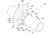
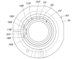
- the shock absorber 11A of the second embodiment includes a spring receiving member 91A that is partially different from the spring receiving member 91 instead of the spring receiving member 91.
- the spring bearing member 91A has a tubular portion 92A that is partially different from the tubular portion 92 instead of the tubular portion 92.
- the cylindrical portion 92A has a small-diameter cylindrical portion 101A, which is partially different from the small-diameter cylindrical portion 101, instead of the small-diameter cylindrical portion 101A.
- the small-diameter tubular portion 101A differs from the small-diameter tubular portion 101 in that a through hole 111A is formed instead of the groove portion 111. That is, the small-diameter tubular portion 101A has a through-hole 111A (communication portion) radially penetrating the small-diameter tubular portion 101A in its axially intermediate portion. In other words, the through hole 111A penetrates the small-diameter cylindrical portion 101A from its inner peripheral surface to its outer peripheral surface.
- a plurality of through holes 111A having the same shape are formed in the small diameter tubular portion 101A at equal intervals in the circumferential direction of the small diameter tubular portion 101A, specifically at three locations.
- the small-diameter cylindrical portion 101A has a base portion 115A, an extension portion 116A, and a tip portion 141A.
- the base portion 115A has substantially the same shape as the base portion 115, but differs in that the length in the axial direction is shorter.
- the extending portion 116A extends from the base portion 115A to the side opposite to the contact portion 102 in the axial direction of the small-diameter tubular portion 101A.
- the tip portion 141A is provided on the side opposite to the base portion 115A of the extension portion 116A in the axial direction of the small-diameter cylindrical portion 101A, and connects the plurality of extension portions 116A.
- the distal end portion 141A has a cylindrical shape over the entire length in the axial direction. Extending portions 116A having the same shape are formed in the small-diameter tubular portion 101A at equal intervals in the circumferential direction of the small-diameter tubular portion 101A, specifically at three locations.
- the spring receiving member 91A is fitted to the second large diameter portion 43 of the first cylindrical portion 31 at the small diameter cylindrical portion 101A of the cylindrical portion 92A. 21, and the contact portion 102 abuts on the end face of the contact ring 81 on the side of the opening 24 (see FIG. 1) in the axial direction.
- the spring receiving member 91A is such that the through hole 111A provided in the tubular portion 92A is positioned between the outer peripheral surface side of the second large diameter portion 43 of the cylinder 21 and the outer peripheral surface side of the small diameter tubular portion 101A of the tubular portion 92A. communicate.
- the spring receiving member 91A contacts the contact ring 81 (see FIG. 1) attached to the cylinder 21 at the contact portion 102 of the tubular portion 92A.
- the band member 131 is arranged such that the plurality of extending portions 116A and the plurality of through holes 111A of the spring receiving member 91A overlap with the axial positions of the small-diameter cylindrical portion 101A. 101A of the plurality of extending portions 116A. After that, the band member 131 is tightened.
- the band member 131 faces the radially outer outer surface of the small-diameter cylindrical portion 101A of the plurality of extending portions 116A at a part of the serrations (not shown) on the inner peripheral surface of the band-shaped portion 132, and these pressed against the outer surface of the
- the belt-like portion 132 of the band member 131 enters the plurality of through-holes 111A of the small-diameter cylindrical portion 101A, and part of the serrations (not shown) on the inner peripheral surface of the band member 131 extend to the second large-diameter portion of the cylinder 21. It faces the outer peripheral surface of the portion 43 and is pressed against the outer peripheral surface.
- the band member 131 is pressed against the radially outer surface of the small-diameter cylindrical portion 101A of the plurality of extending portions 116A in a plurality of regions in which the band-shaped portion 132 is spaced apart in the longitudinal direction. At the same time, the band member 131 is pressed against the outer peripheral surface of the second large diameter portion 43 in a plurality of regions in which the strip portion 132 is spaced apart in the longitudinal direction.
- the band member 131, the spring receiving member 91A and the cylinder 21 are fixed by the frictional force of the band-shaped portion 132.
- the band member 131 suppresses the movement of the spring bearing member 91A to both sides in the circumferential direction of the cylinder 21 relative to the cylinder 21, and suppresses the movement of the cylinder 21 to both sides in the axial direction of the cylinder 21.
- the band member 131 abuts against the outer peripheral surface of the cylinder 21 and the cylindrical portion 92A to suppress relative movement in the circumferential direction and relative movement in the axial direction between the cylinder 21 and the spring receiving member 91A.
- the movement of the spring bearing member 91A toward the bottom portion 23 (see FIG. 1) in the axial direction of the cylinder 21 is restricted by the contact ring 81 (see FIG. 1).
- the band member 131 abuts against the outer peripheral surface of the cylinder 21 and the cylindrical tubular portion 92A of the spring receiving member 91A that covers at least a portion of the cylinder 21. Circumferential movement relative to the spring receiving member 91A is suppressed. In this way, in the shock absorber 11A, since the band member 131 abuts against the outer peripheral surface of the cylinder 21 and the cylindrical portion 92A of the spring bearing member 91A, the frictional force causes the cylinder 21 and the spring bearing member 91A to move in the circumferential direction. relative movement can be effectively suppressed.
- the damper 11A moves the spring receiving member 91A restricted by the contact ring 81 (see FIG. 1) in the axial direction with respect to the cylinder 21 in the direction of the bottom portion 23 (see FIG. 1).
- the band member 131 restrains the axial movement of the spring bearing member 91A with respect to the cylinder 21 in the direction opposite to the bottom portion 23, which is not restricted by the band member 81.
- the shock absorber 11A can suppress the deformation of the cylinder 21 because the band member 131 only needs to contact the outer peripheral surface of the cylinder 21 and the cylindrical portion 92A of the spring receiving member 91A.
- the shock absorber 11A also has a through hole 111A that is provided in the cylindrical portion 92A of the spring receiving member 91A and communicates the outer peripheral surface side of the cylinder 21 and the outer peripheral surface side of the cylindrical portion 92A. Therefore, the buffer 11A can easily bring the band member 131 into contact with the outer peripheral surface of the cylinder 21 and the outer peripheral surface of the cylindrical portion 92A.
- the band member 131 can easily pass through the tubular portion 92A in the radial direction.
- the shock absorber 11B of the third embodiment includes a spring receiving member 91B that is partially different from the spring receiving member 91 instead of the spring receiving member 91.
- the spring receiving member 91B has a tubular portion 92B that is partially different from the tubular portion 92 instead of the tubular portion 92.
- the tubular portion 92B has a small-diameter tubular portion 101B, which is partially different from the small-diameter tubular portion 101, in place of the small-diameter tubular portion 101.
- the small-diameter tubular portion 101B differs from the small-diameter tubular portion 101 in that a notch portion 111B is formed instead of the groove portion 111. That is, the small-diameter tubular portion 101B has a cutout portion 111B formed at the tip portion on the side opposite to the contact portion 102 in the axial direction so that at least a part of the axial length of the small-diameter tubular portion 101B is shortened. (communication part) is formed. Specifically, the notch portion 111B has a shape obtained by cutting the small-diameter cylindrical portion 101B along a plane that is not perpendicular to the central axis.
- the small-diameter cylindrical portion 101B has a base portion 115B and an extension portion 116B.
- the base portion 115B is provided on the contact portion 102 side in the axial direction of the small-diameter cylindrical portion 101B, and has a cylindrical shape over the entire length in the axial direction.
- the extending portion 116B protrudes from the base portion 115B in the axial direction of the small-diameter tubular portion 101B to the side opposite to the contact portion 102. As shown in FIG. Only one extending portion 116B is formed in the small-diameter tubular portion 101B.
- the extension portion 116B has a planar end surface that is not perpendicular to the central axis of the small-diameter tubular portion 101B on the opposite side of the contact portion 102 in the axial direction of the small-diameter tubular portion 101B.
- the spring receiving member 91B is fitted to the second large diameter portion 43 of the first cylindrical portion 31 at the small diameter cylindrical portion 101B of the cylindrical portion 92B. 21, and the contact portion 102 abuts on the end face of the contact ring 81 on the side of the opening 24 (see FIG. 1) in the axial direction.
- the spring receiving member 91B is configured such that the cutout portion 111B provided in the tubular portion 92B is positioned between the outer peripheral surface side of the second large diameter portion 43 of the cylinder 21 and the outer peripheral surface side of the small diameter tubular portion 101B of the tubular portion 92B. communicate.
- the band member 131 is arranged so that the extending portion 116B and the notch portion 111B of the spring receiving member 91B overlap with the small-diameter cylindrical portion 101B in the axial direction. It is arranged and wound around the outer surface in the radial direction of the small-diameter cylindrical portion 101B of the extension portion 116B at one location. After that, the band member 131 is tightened. Then, at least part of the inner peripheral surface of the band member 131 contacts the outer peripheral surface of the cylindrical portion 92B and the outer peripheral surface of the cylinder 21, and the surface facing the cylindrical portion 92B and the surface facing the cylinder 21 are separated. It becomes a state to have.
- the band member 131 faces the outer surface in the radial direction of the small-diameter cylindrical portion 101B of the extension portion 116B at one portion of the serrations (not shown) on the inner peripheral surface of the band-shaped portion 132, It abuts and presses against this outer surface.
- the belt-like portion 132 of the band member 131 enters the space defined by the notch portion 111B of the small-diameter cylindrical portion 101B, and part of the serrations (not shown) on the inner peripheral surface of the band member 131 are pushed into the second large-diameter portion of the cylinder 21. It faces the outer peripheral surface of 43 and contacts and is pressed against this outer peripheral surface.
- the band member 131, the spring receiving member 91B, and the cylinder 21 are fixed by the frictional force of the band-shaped portion 132.
- the band member 131 suppresses the movement of the spring bearing member 91B to both sides in the circumferential direction of the cylinder 21 relative to the cylinder 21, and suppresses the movement of the cylinder 21 to both sides in the axial direction of the cylinder 21.
- the band member 131 abuts against the outer peripheral surface of the cylinder 21 and the cylindrical portion 92B to suppress relative movement in the circumferential direction and relative movement in the axial direction between the cylinder 21 and the spring receiving member 91B.
- the movement of the spring bearing member 91B toward the bottom portion 23 (see FIG. 1) in the axial direction of the cylinder 21 is restricted by the contact ring 81 (see FIG. 1).
- the band member 131 contacts the outer peripheral surface of the cylinder 21 and the cylindrical cylindrical portion 92B of the spring receiving member 91B covering at least a part of the cylinder 21, thereby Circumferential movement relative to the spring receiving member 91B is suppressed. Since the band member 131 abuts against the outer peripheral surface of the cylinder 21 and the cylindrical portion 92B of the spring receiving member 91B, the shock absorber 11B moves the cylinder 21 and the spring receiving member 91B in the circumferential direction due to the frictional force. relative movement can be effectively suppressed.
- the shock absorber 11B since the band member 131 abuts against the outer peripheral surface of the cylinder 21 and the cylindrical portion 92B of the spring receiving member 91B, the frictional force between the cylinder 21 and the spring receiving member 91B in the axial direction is reduced. Movement can also be effectively suppressed. That is, the shock absorber 11B moves axially toward the bottom portion 23 (see FIG. 1) with respect to the cylinder 21 of the spring receiving member 91B, which is restricted by the contact ring 81 (see FIG. 1), and also moves the contact ring 81 (see FIG. 1).
- the band member 131 restrains the axial movement of the spring receiving member 91B with respect to the cylinder 21 in the direction opposite to the bottom portion 23, which is not restricted by the band member 81. Therefore, in the shock absorber 11B, relative movement between the cylinder 21 and the spring receiving member 91B can be effectively suppressed. Of course, since the band member 131 of the shock absorber 11B only needs to contact the outer peripheral surface of the cylinder 21 and the cylindrical portion 92B of the spring bearing member 91B, the deformation of the cylinder 21 can be suppressed.
- the shock absorber 11B also has a notch portion 111B provided in the cylindrical portion 92B of the spring receiving member 91B and communicating between the outer peripheral surface side of the cylinder 21 and the outer peripheral surface side of the cylindrical portion 92B. Therefore, the buffer 11B can easily bring the band member 131 into contact with the outer peripheral surface of the cylinder 21 and the outer peripheral surface of the tubular portion 92B.
- the band member 131 is configured to pass through the cylindrical portion 92B in the radial direction. can be easily formed.
- the shock absorber 11C of the fourth embodiment includes a spring receiving member 91C that is partially different from the spring receiving member 91 instead of the spring receiving member 91.
- the spring receiving member 91 ⁇ /b>C has a tubular portion 92 ⁇ /b>C that is partially different from the tubular portion 92 instead of the tubular portion 92 .
- the cylindrical portion 92 ⁇ /b>C has a small-diameter cylindrical portion 101 ⁇ /b>C that is partially different from the small-diameter cylindrical portion 101 instead of the small-diameter cylindrical portion 101 .
- the small-diameter tubular portion 101C differs from the small-diameter tubular portion 101 in that it has an extension portion 116C that is partially different from the extension portion 116 instead of the extension portion 116 .
- a plurality of, specifically three, extension portions 116C having the same shape are engaged with the radially outer outer surface of the small-diameter tubular portion 101C so as to be recessed inward in the radial direction of the small-diameter tubular portion 101C.
- a groove 151C is formed.
- the extending portion 116C differs from the extending portion 116 in this point.
- 151 C of several engaging grooves have penetrated the extending part 116C in which each was provided in the circumferential direction of the small diameter cylinder part 101C. All the engagement grooves 151C of the small-diameter cylindrical portion 101C are arranged on the same circle. All of the engaging grooves 151C of the small-diameter cylindrical portion 101C have groove bottom surfaces on the inner side in the recess direction arranged on the same cylindrical surface.
- the shock absorber 11C includes a ring member 131C (second movement suppressing portion) different from the band member 131 instead of the band member 131.
- 131 C of ring members are endless, ie, are formed annularly.
- the ring member 131C is an integrally molded product made of one member made of an elastically deformable rubber material.
- the ring member 131C is specifically a square ring.
- the spring receiving member 91C is fitted to the second large diameter portion 43 of the first cylindrical portion 31 at the small diameter cylindrical portion 101C of the cylindrical portion 92C. 21, and the contact portion 102 abuts on the end face of the contact ring 81 on the side of the opening 24 (see FIG. 1) in the axial direction.
- the ring member 131C is stretched in the circumferential direction as a whole and expanded in diameter, and as shown in FIG.
- the plurality of grooves 111 and the small-diameter cylindrical portion 101C are arranged so as to overlap each other in the axial direction, and face the radially outer surface of the small-diameter cylindrical portion 101C of the plurality of extending portions 116C.
- the diameter expansion of the ring member 131C is released.
- the ring member 131C is reduced in diameter to enter and engage with the plurality of engagement grooves 151C, and at least a portion of the inner peripheral surface of the ring member 131C is a portion of the outer peripheral surface of the tubular portion 92C.
- the ring member 131C faces the groove bottom surfaces of the plurality of engagement grooves 151C, which are the radially outer outer surfaces of the small-diameter cylindrical portions 101C of the plurality of extension portions 116C. , are pressed against these groove bottoms.
- the ring member 131C enters into the plurality of grooves 111, faces the outer peripheral surface of the second large-diameter portion 43 of the cylinder 21 at a part of the inner peripheral surface, and abuts and presses the outer peripheral surface. be done.
- the ring member 131C is pressed against the groove bottom surfaces of the plurality of engagement grooves 151C in a plurality of regions spaced apart in the circumferential direction. At the same time, the ring member 131C is pressed against the outer peripheral surface of the second large-diameter portion 43 in a plurality of regions spaced apart in the circumferential direction.
- the ring member 131C, the spring receiving member 91C, and the cylinder 21 are fixed by the frictional force of the ring member 131C.
- the ring member 131C suppresses the movement of the spring bearing member 91C to both sides in the circumferential direction of the cylinder 21 relative to the cylinder 21, and suppresses the movement of the cylinder 21 to both sides in the axial direction of the cylinder 21.
- the ring member 131C abuts against the outer peripheral surface of the cylinder 21 and the cylindrical portion 92C to suppress relative movement in the circumferential direction and relative movement in the axial direction between the cylinder 21 and the spring receiving member 91C.
- the movement of the spring receiving member 91C toward the bottom portion 23 (see FIG. 1) in the axial direction of the cylinder 21 is restricted by the contact ring 81 (see FIG. 1).
- the ring member 131C abuts against the outer peripheral surface of the cylinder 21 and the cylindrical tubular portion 92C of the spring receiving member 91C that covers at least a portion of the cylinder 21. Circumferential movement relative to the spring receiving member 91C is suppressed. Since the ring member 131C abuts against the outer peripheral surface of the cylinder 21 and the cylindrical portion 92C of the spring receiving member 91C, the shock absorber 11C is configured to move the cylinder 21 and the spring receiving member 91C in the circumferential direction due to the frictional force. relative movement can be effectively suppressed.
- the ring member 131C contacts the outer peripheral surface of the cylinder 21 and the cylindrical portion 92C of the spring bearing member 91C, the frictional force between the cylinder 21 and the spring bearing member 91C in the axial direction of the shock absorber 11C is reduced. Movement can also be effectively suppressed. That is, the shock absorber 11C moves the spring receiving member 91C, which is restricted by the contact ring 81 (see FIG. 1), in the axial direction with respect to the cylinder 21 in the direction of the bottom portion 23 (see FIG. 1). The ring member 131C suppresses axial movement of the spring bearing member 91C with respect to the cylinder 21 in the direction opposite to the bottom portion 23, which is not restricted by the ring member 81.
- shock absorber 11C relative movement between the cylinder 21 and the spring receiving member 91C can be effectively suppressed.
- the shock absorber 11C can suppress the deformation of the cylinder 21 because the ring member 131C only needs to contact the outer peripheral surface of the cylinder 21 and the cylindrical portion 92C of the spring receiving member 91C.
- the shock absorber 11C uses a ring member 131C formed of a rubber material in an annular shape, the ring member 131C is mounted so as to contact the outer peripheral surface of the cylinder 21 and the cylindrical cylindrical portion 92C of the spring receiving member 91C. can be easily done. Moreover, the shock absorber 11C can suppress an increase in weight due to the ring member 131C, and can suppress an increase in component cost.
- the shock absorber 11D of the fifth embodiment includes a spring receiving member 91D that is partially different from the spring receiving member 91 instead of the spring receiving member 91.
- the spring receiving member 91 ⁇ /b>D has a tubular portion 92 ⁇ /b>D that is partially different from the tubular portion 92 instead of the tubular portion 92 .
- the tubular portion 92 ⁇ /b>D has a small-diameter tubular portion 101 ⁇ /b>D that is partially different from the small-diameter tubular portion 101 instead of the small-diameter tubular portion 101 .
- the small-diameter tubular portion 101D differs from the small-diameter tubular portion 101 in that the groove portion 111 is replaced with a groove portion 111D (communication portion) that is partially different from the groove portion 111 .
- the cylindrical portion 92D has a plurality of, specifically three, same-shaped projecting portions 161D.
- the protruding portion 161D protrudes outward from the small-diameter tubular portion 101D in the radial direction of the small-diameter tubular portion 101D.
- a plurality, specifically three, of the grooves 111D having the same shape are such that the groove bottom surface (axial end face) on the side of the contact portion 102 in the axial direction of the small-diameter cylindrical portion 101D is the projecting portion 161D in the axial direction of the small-diameter cylindrical portion 101D. has a surface opposite to the contact portion 102 .
- a protruding portion 161D that protrudes radially outward is formed on the groove bottom surface of the groove portion 111D.
- the groove portion 111D has substantially the same shape as the groove portion 111. As shown in FIG.
- the small-diameter cylindrical portion 101D has a cylindrical shape over its entire length before completion.
- the tip portion of the small-diameter cylindrical portion 101D is cut so as to form both side surfaces of the groove portion 111D.
- a groove portion 111D is formed.
- the plurality of protruding portions 161D are arranged on the same plane, and then processed appropriately so that the tip surfaces on the protruding side are arranged on the same cylindrical surface. Therefore, the spring receiving member 91D is an integrally molded product made of a single metal member including all the projecting portions 161D.
- the band member 131 fixes the spring receiving member 91 and the cylinder 21 to each other. At that time, the band-shaped portion 132 of the band member 131 enters the plurality of grooves 111D of the small-diameter cylindrical portion 101D and is pressed against the outer peripheral surface of the second large-diameter portion 43 of the cylinder 21 .
- a dust cover 165D is provided radially outwardly of the shock absorber 11D to cover at least a portion of the cylinder 21 or at least a portion of the tubular portion 92D radially outwardly.
- the dust cover 165D covers a range from the end of the second large diameter portion 43 of the first cylindrical portion 31 of the cylinder 21 on the side of the intermediate locking portion 32 to a predetermined intermediate position in the axial direction, and the intermediate locking portion 32 , the second cylindrical portion 33 and the end locking portion 34 .
- the dust cover 165D covers a range from the end opposite to the contact portion 102 in the axial direction of the small-diameter cylindrical portion 101D of the spring bearing member 91D to a predetermined position closer to the contact portion 102 than the projecting portion 161D. . Therefore, the dust cover 165D also covers the radially outer side of the band member 131 . In other words, the dust cover 165D has the band member 131 arranged within its radial inner axial range. The dust cover 165D is arranged radially between the suspension spring 125 and the shock absorber 11D.
- the dust cover 165D is made of synthetic resin and formed in a bellows tube shape, and expands and contracts in its axial direction.
- the dust cover 165D has an engaging recess 166D formed at one end in the axial direction thereof, the engaging recess 166D being recessed from the inner side to the outer side in the radial direction.
- the engaging recess 166D is annular.
- the dust cover 165D covers at least a portion of the cylinder 21 and at least a portion of the cylindrical portion 92D, and the engaging recess 166D located at the axial end on the side of the spring receiving member 91D engages the spring. It engages with a plurality of protrusions 161D of the receiving member 91D.
- the buffer 11D of the fifth embodiment has the same effects as the buffer 11 does.
- at least a portion of a dust cover 165D that covers at least a portion of the cylinder 21 or at least a portion of the cylindrical portion 92D is restrained from axially moving relative to the cylinder 21 by the projecting portion 161D of the spring receiving member 91D. be done. Therefore, the shock absorber 11D does not require a dedicated component for suppressing the axial movement of at least a portion of the dust cover 165D with respect to the cylinder 21. Therefore, the shock absorber 11D can reduce the number of parts and cost.
- the shock absorber 11E of the sixth embodiment includes a spring receiving member 91E that is partially different from the spring receiving member 91 instead of the spring receiving member 91.
- the spring bearing member 91E has a tubular portion 92E that is partially different from the tubular portion 92 instead of the tubular portion 92.
- the tubular portion 92E has a small-diameter tubular portion 101E, which is partially different from the small-diameter tubular portion 101, in place of the small-diameter tubular portion 101.
- FIG. As shown in FIG. As shown in FIG.
- the small-diameter cylindrical portion 101E has a groove portion 111E (communicating portion) that has a shape substantially similar to that of the groove portion 111 and that is deeper than the groove portion 111 in the axial direction of the small-diameter cylindrical portion 101E. are doing. Accordingly, the small-diameter tubular portion 101E has a base portion 115E having substantially the same shape as the base portion 115 and having a shorter axial length than the base portion 115 instead of the base portion 115. As shown in FIG.
- the small-diameter tubular portion 101E has a plurality of extension portions 116E that have substantially the same shape as the extension portion 116 and that are longer than the extension portion 116 in the axial direction of the small-diameter tubular portion 101E. I have it instead.
- the shock absorber 11E includes a ring member 131E (second movement suppressing portion) different from the band member 131 instead of the band member 131.
- the ring member 131E is endless, that is, formed in an annular shape.
- the ring member 131E is an integrally molded product made of one member made of an elastically deformable rubber material.
- the ring member 131E is formed with a housing groove 171E that is recessed radially inward from the outer peripheral surface in an axially intermediate portion thereof.
- the accommodation groove 171E is annular.
- the ring member 131E has an engagement flange portion 172E projecting radially outward from the bottom surface of the accommodation groove 171E on one side of the accommodation groove 171E in the axial direction.
- the other side of the groove 171E is a flange portion 173E projecting radially outward from the groove bottom surface of the housing groove 171E.
- Both the engagement flange portion 172E and the flange portion 173E are annular.
- the engaging flange portion 172E is chamfered at the outer peripheral portion of the axial end opposite to the flange portion 173E.
- the engaging flange portion 172E and the accommodation groove 171E form a stepped portion 175E formed so that a portion of the outer peripheral surface of the ring member 131E forms a stepped portion.
- the spring receiving member 91E is fitted to the second large diameter portion 43 of the first cylindrical portion 31 at the small diameter cylindrical portion 101E of the cylindrical portion 92E in the same manner as the spring receiving member 91.
- the contact ring 81 attached to the cylinder 21 is fitted in the diameter cylindrical portion 103 , and the contact portion 102 contacts the end surface of the contact ring 81 on the opening 24 side in the axial direction.
- the ring member 131E is expanded in diameter as a whole, and as shown in FIG. They are arranged so that their positions in the direction overlap each other, and face the radially outer outer surface of the small-diameter tubular portion 101E of the plurality of extension portions 116E. At this time, the ring member 131E is oriented so that the flange portion 173E is located closer to the contact portion 102 than the engaging flange portion 172E in the axial direction of the small-diameter cylindrical portion 101E. After that, the ring member 131E is released from the expanded diameter.
- the ring member 131E is reduced in diameter, and at least a part of its inner peripheral surface abuts against the outer peripheral surface of the cylindrical portion 92E and the outer peripheral surface of the cylinder 21, so that the surface facing the cylindrical portion 92E and the It is in a state of having a surface facing the cylinder 21 .
- a part of the inner peripheral surface of the ring member 131E faces the radially outer outer surfaces of the small-diameter cylindrical portions 101E of the plurality of extension portions 116E, and is pressed against these outer surfaces.
- the ring member 131E enters the plurality of grooves 111E, faces the outer peripheral surface of the second large-diameter portion 43 of the cylinder 21 at a part of the inner peripheral surface, and abuts and presses the outer peripheral surface. be done.
- the ring member 131E is pressed against the radially outer surface of the small-diameter cylindrical portion 101E of the plurality of extension portions 116E at a plurality of regions spaced apart in the circumferential direction.
- the ring member 131E is pressed against the outer peripheral surface of the second large-diameter portion 43 at a plurality of regions spaced apart in the circumferential direction.
- the ring member 131E, the spring receiving member 91E, and the cylinder 21 are fixed by the frictional force of the ring member 131E.
- the ring member 131E suppresses the movement of the spring receiving member 91E to both sides in the circumferential direction of the cylinder 21 relative to the cylinder 21, and suppresses the movement of the cylinder 21 to both sides in the axial direction of the cylinder 21.
- the ring member 131E abuts against the outer peripheral surface of the cylinder 21 and the cylindrical portion 92E to suppress relative movement in the circumferential direction and the relative movement in the axial direction between the cylinder 21 and the spring bearing member 91E.
- a dust cover 165E that covers at least part of the cylinder 21 or at least part of the cylindrical portion 92E is provided radially outwardly of the shock absorber 11E.
- the dust cover 165E covers a range from the end of the second large diameter portion 43 of the first cylindrical portion 31 of the cylinder 21 on the side of the intermediate locking portion 32 in the axial direction to a predetermined intermediate position, and the intermediate locking portion 32 , the second cylindrical portion 33 and the end locking portion 34 .
- the dust cover 165E covers a range from the end of the small-diameter cylindrical portion 101E of the spring receiving member 91E opposite to the contact portion 102 in the axial direction to a predetermined position on the end side of the groove bottom surface of the groove portion 111E. cover.
- the dust cover 165E is arranged radially between the suspension spring 125 and the shock absorber 11E.
- the dust cover 165E is made of synthetic resin and formed in a bellows tube shape, and expands and contracts in its axial direction.
- the dust cover 165E is formed with an engaging recess 166E recessed from the inner side to the outer side in the radial direction at one end in the axial direction.
- the engaging recess 166E is annular.
- the dust cover 165E covers at least a portion of the cylinder 21 and at least a portion of the cylindrical portion 92E, and the engaging recess 166E located at the axial end on the side of the spring receiving member 91E is a ring. It engages with the engagement flange portion 172E of the stepped portion 175E of the member 131E.
- the ring member 131E abuts against the outer peripheral surface of the cylinder 21 and the cylindrical tubular portion 92E of the spring receiving member 91E that covers at least a portion of the cylinder 21. Circumferential movement relative to the spring receiving member 91E is suppressed. Since the ring member 131E abuts against the outer peripheral surface of the cylinder 21 and the cylindrical portion 92E of the spring receiving member 91E, the shock absorber 11E moves the cylinder 21 and the spring receiving member 91E in the circumferential direction due to the frictional force. relative movement can be effectively suppressed.
- the buffer 11E moves the spring receiving member 91E, which is restricted by the contact ring 81, in the axial direction relative to the cylinder 21 in the direction of the bottom portion 23, and the spring receiving member 91E, which is not restricted by the contact ring 81, Axial movement of the cylinder 21 in the direction opposite to the bottom portion 23 is suppressed by the ring member 131E.
- the shock absorber 11E can effectively suppress the relative movement between the cylinder 21 and the spring receiving member 91E.
- the shock absorber 11E can suppress the deformation of the cylinder 21 because the ring member 131E only needs to contact the outer peripheral surface of the cylinder 21 and the cylindrical portion 92E of the spring receiving member 91E.
- the shock absorber 11E uses a ring member 131E formed of a rubber material in an annular shape, the ring member 131E is mounted so as to contact the outer peripheral surface of the cylinder 21 and the cylindrical cylindrical portion 92E of the spring bearing member 91E. can be easily done. Moreover, the shock absorber 11E can suppress an increase in weight due to the ring member 131E, and can suppress an increase in component cost.
- the shock absorber 11E in the shock absorber 11E, at least a portion of the dust cover 165E that covers at least a portion of the cylinder 21 or at least a portion of the cylindrical portion 92E is restrained from axially moving relative to the cylinder 21 by the stepped portion 175E of the ring member 131E. be. Therefore, the shock absorber 11E does not require a dedicated component for suppressing the axial movement of at least a part of the dust cover 165E with respect to the cylinder 21. Therefore, the shock absorber 11E can reduce the number of parts and costs.
- the shock absorber 11F of the seventh embodiment has a cylinder 21F that is partially different from the cylinder 21 instead of the cylinder 21.
- the cylinder 21 ⁇ /b>F has a body portion 22 ⁇ /b>F that is partially different from the body portion 22 instead of the body portion 22 .
- the body portion 22 ⁇ /b>F has a first cylindrical portion 31 ⁇ /b>F (cylindrical portion) that is partially different from the first cylindrical portion 31 instead of the first cylindrical portion 31 .
- the first cylindrical portion 31F includes a second large diameter portion 43F partially different from the second large diameter portion 43, a third large diameter portion 181F partially different from the second large diameter portion 43, and a second small diameter portion 182F. , instead of the second large diameter portion 43 .
- the first cylindrical portion 31F has a cylindrical shape over the entire length in the axial direction. , a second small diameter portion 182F, and a third large diameter portion 181F.
- the second large diameter portion 43 ⁇ /b>F has substantially the same shape as the second large diameter portion 43 and has a shorter axial length than the second large diameter portion 43 .
- the third large diameter portion 181 ⁇ /b>F also has substantially the same shape as the second large diameter portion 43 and has a shorter axial length than the second large diameter portion 43 .
- the second small-diameter portion 182F has a radially outer peripheral surface that is cylindrical, and a radially inner peripheral surface that is coaxial with the outer peripheral surface.
- the second small diameter portion 182F has an inner diameter equal to the inner diameters of the first large diameter portion 41, the small diameter portion 42, the second large diameter portion 43F, and the third large diameter portion 181F, and the outer diameter of the first large diameter portion.
- the diameter is smaller than the outer diameter of the second large diameter portion 43F and the third large diameter portion 181F.
- the first large-diameter portion 41, the small-diameter portion 42, the second large-diameter portion 43F, the second small-diameter portion 182F, and the third large-diameter portion 181F share a central axis.
- the first cylindrical portion 31F has a fitting groove 45 on the outer diameter side of the small diameter portion 42 between the first large diameter portion 41 and the second large diameter portion 43F in the axial direction.
- the fitting groove 45 is recessed radially inward from the outer peripheral surface of the first large diameter portion 41 and the outer peripheral surface of the second large diameter portion 43F.
- the fitting groove 45 is annular.
- the first cylindrical portion 31F is between the second large diameter portion 43F and the third large diameter portion 181F in the axial direction, and the outer diameter side of the second small diameter portion 182F forms the second fitting groove 185F.
- the second fitting groove 185F is recessed radially inward from the outer peripheral surface of the second large diameter portion 43F and the outer peripheral surface of the third large diameter portion 181F.
- the second fitting groove 185F is annular.
- the shock absorber 11F has a spring receiving member 91F that is partially different from the spring receiving member 91 instead of the spring receiving member 91.
- the spring receiving member 91 ⁇ /b>F has a tubular portion 92 ⁇ /b>F that is partially different from the tubular portion 92 instead of the tubular portion 92 .
- the tubular portion 92 ⁇ /b>F has a small-diameter tubular portion 101 ⁇ /b>F that is partially different from the small-diameter tubular portion 101 instead of the small-diameter tubular portion 101 .
- the small-diameter tubular portion 101F differs from the small-diameter tubular portion 101 in that instead of the plurality of extension portions 116, it has an axial projection portion 116F. are doing.
- the axial projecting portion 116F projects from the base portion 115 in the direction opposite to the contact portion 102 along the axial direction of the small-diameter tubular portion 101F. Only one axial projection 116F is formed on the small-diameter cylindrical portion 101F.
- the shock absorber 11F has a ring member 131F (second movement suppressing portion).
- the ring member 131F is made of metal and has a main body portion 192F and a pair of protrusions 193F.
- the main body portion 192F has a C shape formed by dividing the ring at one point in the circumferential direction.
- the main body portion 192F has a radially outer peripheral surface that is cylindrical, and a radially inner peripheral surface that is coaxial with the outer peripheral surface.
- the pair of projecting portions 193F protrude outward in the radial direction of the main body portion 192F from both ends of the main body portion 192F on the dividing side in the circumferential direction.
- the ring member 131F has a thickness in the axial direction of the main body portion 192F that is smaller than the width of the main body portion 192F in the radial direction. Engagement holes 195F are formed in the pair of protrusions 193F so as to extend through the main body 192F along the axial direction.
- the ring member 131F is a snap ring.
- the spring receiving member 91F Similar to the spring receiving member 91, the spring receiving member 91F, as shown in FIG.
- the diameter cylindrical portion 103 is fitted to the contact ring 81 mounted on the cylinder 21F, and the contact portion 102 contacts the end face of the contact ring 81 on the opening 24 side in the axial direction.
- the side surface of the second fitting groove 185F on the side of the bottom portion 23 in the axial direction of the cylinder 21F is flush with the end surface of the base portion 115 of the spring bearing member 91F on the side opposite to the contact portion 102 in the axial direction.
- the ring member 131F is fitted into the second fitting groove 185F of the cylinder 21F.
- the ring member 131F has the axial protrusion 116F of the spring receiving member 91F arranged between the pair of protrusions 193F in the circumferential direction.
- the ring member 131F has an inner diameter before being fitted into the second fitting groove 185F shown in FIG. It has a slightly smaller diameter. Therefore, the ring member 131F is abutted against and pressed against the bottom surface of the second fitting groove 185F on the deep side in the recess direction. Therefore, when the ring member 131F is fitted into the second fitting groove 185F, the frictional force prevents the ring member 131F from moving to both sides in the circumferential direction with respect to the cylinder 21F.
- the outer diameter of the main body portion 192F is larger than the outer diameters of the second large diameter portion 43F and the third large diameter portion 181F. Therefore, the ring member 131F is provided on the first cylindrical portion 31F of the cylinder 21F and protrudes radially outward from the first cylindrical portion 31F of the cylinder 21F.
- the ring member 131F When the ring member 131F is fitted into the second fitting groove 185F, the ring member 131F abuts against the axial end face of the base portion 115 of the spring receiving member 91F on the side opposite to the contact portion 102, thereby compressing the cylinder of the spring receiving member 91F. It regulates the movement of 21F to the side opposite to the bottom portion 23 in the axial direction.
- the main portion 192F of the ring member 131F is located at the circumferential split side end portion of the base portion 115 of the axial projection portion 116F of the spring receiving member 91F. , in contact with at least one of both ends in the circumferential direction to support the axial protrusion 116F.
- the ring member 131F suppresses relative movement in the circumferential direction between the spring receiving member 91F and the cylinder 21F.
- the main body portion 192F of the ring member 131F is in contact with both end surfaces in the circumferential direction of the base portion 115 of the axial projection portion 116F of the spring receiving member 91F at both end surfaces on the dividing side in the circumferential direction. The relative movement of the spring receiving member 91F and the cylinder 21F on both sides in the circumferential direction is suppressed.
- the frictional force of the ring member 131F restrains the spring bearing member 91F from moving to both sides in the circumferential direction of the cylinder 21F relative to the cylinder 21F.
- the ring member 131F restricts the movement of the spring bearing member 91F to the side opposite to the bottom portion 23 in the axial direction of the cylinder 21F relative to the cylinder 21F.
- the ring member 131F abuts against the groove bottom surface of the second fitting groove 185F forming the outer peripheral surface of the cylinder 21F and the axial protrusion 116F of the cylindrical portion 92F, thereby supporting the circumference of the cylinder 21F and the spring receiving member 91F. Restrain directional relative movement and axial relative movement.
- the movement of the spring bearing member 91F toward the bottom portion 23 in the axial direction of the cylinder 21F with respect to the cylinder 21F is restricted by the contact ring 81 as described above.
- the ring member 131F abuts against the outer peripheral surface of the cylinder 21F and the cylindrical tubular portion 92F of the spring bearing member 91F covering at least a portion of the cylinder 21F. Circumferential relative movement with the spring receiving member 91F is suppressed. Since the ring member 131F abuts against the outer peripheral surface of the cylinder 21F and the cylindrical portion 92F of the spring receiving member 91F, the shock absorber 11F can move the cylinder 21F and the spring receiving member 91F in the circumferential direction due to the frictional force. relative movement can be effectively suppressed.
- the shock absorber 11F since the ring member 131F abuts against the outer peripheral surface of the cylinder 21F and the axial protrusion 116F of the cylindrical portion 92F of the spring receiving member 91F, the axial direction of the cylinder 21 and the spring receiving member 91F is reduced. Relative movement can also be effectively suppressed. That is, the shock absorber 11F moves the spring receiving member 91F, which is not restricted by the contact ring 81, in the axial direction toward the bottom portion 23 relative to the cylinder 21. Axial movement of the cylinder 21 in the direction opposite to the bottom portion 23 is restricted by the ring member 131F.
- the shock absorber 11F only requires the ring member 131F to contact the outer peripheral surface of the cylinder 21F and the cylindrical portion 92F of the spring receiving member 91F, so that deformation of the cylinder 21F can be suppressed.
- the spring receiving member 91F has an axial protrusion 116F that protrudes in the axial direction
- the ring member 131F is fixed to the cylinder 21F
- at least one of the circumferential ends of the axial protrusion 116F is fixed to the cylinder 21F. is arranged to abut and support the Therefore, the shock absorber 11F can easily suppress the relative movement between the cylinder 21F and the spring receiving member 91F by the ring member 131F.
- the shock absorber 11G of the eighth embodiment includes a spring receiving member 91G, which is partially different from the spring receiving member 91, instead of the spring receiving member 91.
- the spring receiving member 91G has a tubular portion 92G, which is partially different from the tubular portion 92, instead of the tubular portion 92.
- the cylindrical portion 92 ⁇ /b>G has a small-diameter cylindrical portion 101 ⁇ /b>G that is partially different from the small-diameter cylindrical portion 101 instead of the small-diameter cylindrical portion 101 .
- the small-diameter tubular portion 101 ⁇ /b>G is the same as the base portion 115 of the small-diameter tubular portion 101 . Therefore, the small-diameter cylindrical portion 101G has a cylindrical shape over the entire length in the axial direction.
- the shock absorber 11G includes an abutment ring 81G (first movement suppressing portion) that is partially different from the abutment ring 81 (see FIG. 1) instead of the abutment ring 81.
- the contact ring 81G is made of metal and is a C-shaped C ring formed by dividing a circular ring at one point in the circumferential direction.
- the contact ring 81G has an outer serration portion 202G (second movement suppressing portion) in which a large number of teeth 201G are arranged in the circumferential direction on its radially outer peripheral surface.
- the contact ring 81G also has an inner serration portion (second movement suppressing portion) in which a large number of teeth are arranged in the circumferential direction on the inner peripheral surface on the radially inner side thereof. .
- the contact ring 81 ⁇ /b>G is fitted into the fitting groove 45 provided in the first cylindrical portion 31 of the cylinder 21 . As a result, the contact ring 81G is pressed against the bottom surface of the fitting groove 45 with its inner serrated portion.
- the abutment ring 81G protrudes radially outward from the first cylindrical portion 31 of the cylinder 21 and projects toward both sides in the axial direction of the cylinder 21, similarly to the abutment ring 81. Movement is restricted by the first cylindrical portion 31 .
- the spring receiving member 91G is fitted to the second large diameter portion 43 of the first cylindrical portion 31 at the small diameter cylindrical portion 101G of the cylindrical portion 92G, and abuts at the large diameter cylindrical portion 103. It fits into the ring 81G, and the contact portion 102 abuts on the end surface of the contact ring 81G on the side of the opening 24 (see FIG. 1) in the axial direction. At that time, the large-diameter tubular portion 103 is fitted to the contact ring 81G with a slight interference.
- the outer serration portion 202G abuts and presses the radially inner side of the cylindrical portion 92G, and the inner serration portion (not shown) abuts and presses the radially outer side of the cylinder 21 .
- the contact ring 81G is formed between the bottom surface of the fitting groove 45, which is the outer peripheral surface of the cylinder 21, and the cylindrical cylindrical portion of the spring bearing member 91G that covers at least a portion of the cylinder 21. It abuts against the inner peripheral surface of the large-diameter cylindrical portion 103 of 92G to suppress relative movement in the circumferential direction between the cylinder 21 and the spring receiving member 91G.
- the frictional force between the cylinder 21 and the spring bearing member 91G causes the shock absorber 11G to contact the cylinder 21 and the spring bearing member. Circumferential movement relative to 91G can be effectively suppressed.
- the frictional force between the contact ring 81G and the spring receiving member 91G causes the axial movement of the cylinder 21 and the spring receiving member 91G. Relative movement in direction can also be effectively suppressed.
- the shock absorber 11G restricts the axial movement of the spring bearing member 91G toward the bottom portion 23 (see FIG. 1) with respect to the cylinder 21 by the contact ring 81G, and the bottom portion of the spring bearing member 91G relative to the cylinder 21 23 restrains axial movement in the opposite direction. Therefore, the shock absorber 11G can effectively suppress the relative movement between the cylinder 21 and the spring receiving member 91G.
- the contact ring 81G only needs to contact the outer peripheral surface of the cylinder 21 and the inner peripheral surface of the tubular portion 92G of the spring receiving member 91G, so that deformation occurring in the cylinder 21 can be suppressed. can.
- the shock absorber 11G has an outer serration portion 202G and an inner serration portion (not shown) formed on the radially outer side and the radially inner side of the contact ring 81G. , and the inner serration portion is in contact with the radially outer side of the cylinder 21 . Therefore, the shock absorber 11G can effectively suppress the relative movement in the circumferential direction and the relative movement in the axial direction between the cylinder 21 and the spring receiving member 91G with the single contact ring 81G.
- a serration portion may be provided on the radially inner portion of the large-diameter cylindrical portion 103 of the cylindrical portion 92G that contacts the outer serrated portion 202G of the contact ring 81G.
- a serration portion may be provided on the groove bottom portion of the fitting groove 45, which is the radially outer portion of the cylinder 21 that contacts the inner serration portion (not shown) of the contact ring 81G.
- the shock absorber 11H of the ninth embodiment includes a spring receiving member 91H that is partially different from the spring receiving member 91 instead of the spring receiving member 91.
- the spring receiving member 91H has a tubular portion 92H that is partially different from the tubular portion 92 instead of the tubular portion 92 .
- the tubular portion 92 ⁇ /b>H has a small-diameter tubular portion 101 ⁇ /b>H that is partially different from the small-diameter tubular portion 101 instead of the small-diameter tubular portion 101 .
- the small-diameter cylindrical portion 101H has a notch portion 111H (communication portion) at the tip portion on the side opposite to the contact portion 102 in the axial direction.
- the notch portion 111H is recessed in a notch shape toward the contact portion 102 side in the axial direction of the small-diameter cylindrical portion 101H from the tip surface of the small-diameter cylindrical portion 101H opposite to the contact portion 102 in the axial direction.
- the end surface of the small-diameter tubular portion 101H where the notch portion 111H is formed is the end surface of the tubular portion 92H opposite to the seating portion 93 in the axial direction.
- the notch portion 111H radially penetrates the small-diameter cylindrical portion 101H from the inner peripheral surface to the outer peripheral surface thereof.
- a notch portion 111H is formed at one place in the small-diameter cylindrical portion 101H.
- the notch 111H has groove bottoms on the deep side in the recess direction arranged on the same plane.
- the cutout portion 111H is formed so that at least a portion of the axial length of the tubular portion 92H is shortened.
- the small-diameter tubular portion 101H is similar to the base portion 115 of the small-diameter tubular portion 101, and has a base portion 115H that is shorter in axial length than the base portion 115, and an extension portion 116H.
- the extending portion 116H extends from the base portion 115H to the opposite side of the contact portion 102 in the axial direction of the base portion 115H.
- An extending portion 116H is formed at one location on the small-diameter tubular portion 101H. As for the length in the circumferential direction of the small-diameter cylindrical portion 101H, the notch portion 111H is longer than the extending portion 116H.
- the shock absorber 11H of the ninth embodiment includes an anti-slip member 131H (second movement suppressing portion).
- the anti-slip member 131H has an annular shape, and has a shape in which a part is broken in the circumferential direction.
- the non-slip member 131H is an integrally molded product consisting of one member made of an elastically deformable rubber material.
- the non-slip member 131H has a higher coefficient of friction than the spring receiving member 91H and the cylinder 21 .
- the non-slip member 131H has an accommodation groove 211H that is recessed radially inward from the outer peripheral surface in its axially intermediate portion.
- the accommodation groove 211H has an annular shape, and has a shape in which a part is broken in the circumferential direction.
- one side of the accommodation groove 211H in the axial direction of the anti-slip member 131H forms a flange portion 212H that protrudes radially outward from the bottom surface of the accommodation groove 211H.
- the non-slip member 131H has a flange portion 213H that protrudes radially outward from the groove bottom surface of the accommodation groove 211H on the side opposite to the flange portion 212H of the accommodation groove 211H in the axial direction.
- Both the flange portion 212H and the flange portion 213H are annular, and have a shape in which a portion thereof is broken in the circumferential direction.
- the spring receiving member 91H is fitted to the second large diameter portion 43 of the first cylindrical portion 31 of the cylinder 21 at the small diameter cylindrical portion 101H of the cylindrical portion 92H.
- the contact ring 81 (see FIG. 1) attached to the cylinder 21 is fitted at 103, and the contact portion 102 contacts the end surface of the contact ring 81 on the side of the opening 24 (see FIG. 1) in the axial direction.
- the spring receiving member 91H is such that the cutout portion 111H provided in the tubular portion 92H is positioned between the outer peripheral surface side of the second large diameter portion 43 of the cylinder 21 and the outer peripheral surface side of the small diameter tubular portion 101H of the tubular portion 92H. communicate.
- the anti-slip member 131H is arranged so that the extending portion 116H and the notch portion 111H of the spring receiving member 91H overlap the small-diameter cylindrical portion 101H in the axial direction, thereby forming the second large-diameter portion of the cylinder 21. 43 and the extending portion 116H of the small-diameter tubular portion 101H. Then, the non-slip member 131H faces the radially outer surface of the small-diameter tubular portion 101H of the extension portion 116H and the outer peripheral surface of the second large-diameter portion 43 of the cylinder 21 . In other words, the non-slip member 131H has a surface facing the tubular portion 92H and a surface facing the cylinder 21 .
- the band member 131 is arranged so that the accommodation groove 211H of the anti-slip member 131H and the axial position of the anti-slip member 131H overlap each other, and are wound around the bottom surface of the accommodation groove 211H facing outward in the radial direction. . After that, the band member 131 is tightened. Then, the band member 131 contacts the inner peripheral surface of the band-shaped portion 132 with the groove bottom surface of the accommodation groove 211H of the anti-slip member 131H, and moves the anti-slip member 131H to the second position of the cylinder 21 as shown in FIG.
- the outer peripheral surface of the large-diameter portion 43 and the outer surface of the extension portion 116H of the spring receiving member 91H on the radially outer side of the small-diameter cylindrical portion 101H are pressed.
- the anti-slip member 131H comes into contact with the outer surface of the tubular portion 92H and the outer peripheral surface of the cylinder 21 .
- a part of the anti-slip member 131H faces the radially outer surface of the small-diameter tubular portion 101H of the extension portion 116H, and is pressed against the outer surface.
- a part of the anti-slip member 131H enters the notch 111H of the small-diameter cylindrical portion 101H, faces the outer peripheral surface of the second large-diameter portion 43 of the cylinder 21, and abuts on the outer peripheral surface. be pushed.
- the anti-slip member 131H contacts the outer surface of the cylindrical portion 92H of the spring receiving member 91H and the outer peripheral surface of the second large diameter portion 43 of the cylinder 21, and the surface facing the cylindrical portion 92H It will be in the state which has the surface which opposes the diameter part 43. As shown in FIG. In addition, the anti-slip member 131H faces the outer surface of the cylindrical portion 92H of the spring receiving member 91H and is pressed against the outer surface. At the same time, the non-slip member 131H faces the outer peripheral surface of the second large-diameter portion 43 of the cylinder 21 and comes into contact with and pressed against the outer peripheral surface.
- the band member 131 is in a state where the band-shaped portion 132 is fixed to the anti-slip member 131H by the frictional force of the anti-slip member 131H.
- the anti-slip member 131H, the spring receiving member 91H and the cylinder 21 are fixed by the frictional force of the anti-slip member 131H.
- the band member 131 and the non-slip member 131H prevent the spring receiving member 91H from moving to both sides in the circumferential direction of the cylinder 21 with respect to the cylinder 21, and also prevent the cylinder 21 from moving to both sides in the axial direction of the cylinder 21 with respect to the cylinder 21. Movement is suppressed.
- the band member 131 and the anti-slip member 131H are arranged so that the fastening force of the band member 131 causes the anti-slip member 131H to move between the outer peripheral surface of the cylinder 21 and the radially outer outer surface of the cylindrical portion 92H of the extension portion 116H. to suppress relative movement in the circumferential direction and relative movement in the axial direction between the cylinder 21 and the spring bearing member 91H.
- the band member 131 and the anti-slip member 131H contact the outer peripheral surface of the cylinder 21 and the radially outer surface of the tubular portion 92H of the extension portion 116H, and the spring support is connected to the cylinder 21. Circumferential and axial relative movement with the member 91H is suppressed.
- the band member 131 and the non-slip member 131H have a non-slip member 131H that contacts the cylinder 21 and suppresses sliding relative to the cylinder 21 .
- the movement of the spring bearing member 91H toward the bottom portion 23 (see FIG. 1) in the axial direction of the cylinder 21 is restricted by the contact ring 81 (see FIG. 1).
- the non-slip member 131H out of the band member 131 and the non-slip member 131H is a cylindrical spring bearing member 91H that covers the outer peripheral surface of the cylinder 21 and at least a part of the cylinder 21. It abuts against the cylindrical portion 92H.
- the band member 131 and the non-slip member 131H suppress relative movement in the circumferential direction between the cylinder 21 and the spring receiving member 91H. In this way, the non-slip member 131H out of the band member 131 and the non-slip member 131H abuts against the outer peripheral surface of the cylinder 21 and the cylindrical portion 92H of the spring receiving member 91H.
- the non-slip member 131H of the shock absorber 11H contacts the outer peripheral surface of the cylinder 21 and the cylindrical portion 92H of the spring receiving member 91H. 21 and the spring bearing member 91H can also be effectively restrained from moving relative to each other in the axial direction. That is, the shock absorber 11H moves axially toward the bottom portion 23 (see FIG. 1) of the spring receiving member 91H with respect to the cylinder 21, which is restricted by the contact ring 81 (see FIG. 1).
- the band member 131 and the non-slip member 131H suppress the axial movement of the spring receiving member 91H with respect to the cylinder 21 in the direction opposite to the bottom portion 23, which is not restricted by 81. Therefore, in the shock absorber 11H, relative movement between the cylinder 21 and the spring receiving member 91H can be effectively suppressed.
- the non-slip member 131H out of the band member 131 and the non-slip member 131H contacts the outer peripheral surface of the cylinder 21 and the cylindrical portion 92H of the spring bearing member 91H, and the band member 131 acts as the non-slip member. Since it is sufficient to tighten 131H, deformation occurring in the cylinder 21 can be suppressed.
- the shock absorber 11H also includes a notch portion 111H provided in the cylindrical portion 92H of the spring receiving member 91H to communicate the outer peripheral surface side of the cylinder 21 and the outer peripheral surface side of the cylindrical portion 92H. Therefore, the shock absorber 11H can easily bring the non-slip member 131H out of the band member 131 and the non-slip member 131H into contact with the outer peripheral surface of the cylinder 21 and the outer peripheral surface of the tubular portion 92H.
- the notch 111H of the shock absorber 11H is formed so that at least part of the axial length of the tubular portion 92H is shortened. It is formed in a notch shape. Therefore, the shock absorber 11H can easily form a configuration for the band member 131 and the non-slip member 131H to pass through the cylindrical portion 92H in the radial direction.
- the buffer 11H uses the band member 131 formed in a string shape, the non-slip member 131H is brought into contact with the outer peripheral surface of the cylinder 21 and the cylindrical tubular portion 92H of the spring receiving member 91H.
- the band member 131 can be easily attached.
- the anti-slip member 131H out of the band member 131 and the anti-slip member 131H abuts against the spring receiving member 91H and the cylinder 21 to suppress sliding of the spring receiving member 91H with respect to the cylinder 21. . Therefore, in the shock absorber 11H, relative movement between the cylinder 21 and the spring bearing member 91H can be suppressed more effectively.
- the shock absorber 11H since the band member 131 and the anti-slip member 131H of the anti-slip member 131H are made of a rubber material, the relative movement between the cylinder 21 and the spring bearing member 91H can be more effectively controlled. can be suppressed.
- the anti-slip member 131H of the shock absorber 11H is made of a rubber material, the anti-slip member 131H can be attached so as to contact the outer peripheral surface of the cylinder 21 and the cylindrical portion 92H of the spring receiving member 91H. Easy to do.
- the anti-slip member 131H is made of a rubber material, the shock absorber 11H can suppress an increase in weight due to the anti-slip member 131H and an increase in the cost of parts.
- the shock absorber 11J of the tenth embodiment includes a spring bearing member 91J that is partially different from the spring bearing member 91 instead of the spring bearing member 91.
- the spring receiving member 91J has a tubular portion 92J that is partially different from the tubular portion 92 instead of the tubular portion 92.
- the tubular portion 92J has a small-diameter tubular portion 101J, which is partially different from the small-diameter tubular portion 101, in place of the small-diameter tubular portion 101.
- FIG. As shown in FIG. As shown in FIG.
- the small-diameter tubular portion 101J is different from the small-diameter tubular portion 101 in that the groove portion 111 and the extending portion 116 are not provided at the distal end portion on the side opposite to the contact portion 102 in the axial direction. are different.
- the shock absorber 11J of the tenth embodiment includes an anti-slip member 131J (second movement suppressing portion).
- the non-slip member 131J is formed in an annular shape, as shown in FIG.
- the non-slip member 131J is an integrally molded product made of one member made of an elastically deformable rubber material.
- the non-slip member 131J has a higher coefficient of friction than the cylinder 21 and the spring receiving member 91J.
- the anti-slip member 131J has a substrate portion 221J and an annular portion 222J.
- the substrate portion 221J is cylindrical.
- the annular portion 222J protrudes from the outer peripheral portion of the substrate portion 221J to one side of the substrate portion 221J in the axial direction.
- the annular portion 222J has a cylindrical shape coaxial with the substrate portion 221J.
- the inner diameter of the annular portion 222J is larger than the inner diameter of the substrate portion 221J.
- the annular portion 222J has the same outer diameter as the substrate portion 221J. Therefore, the radial thickness of the annular portion 222J is smaller than the radial thickness of the substrate portion 221J.
- the spring receiving member 91J is fitted to the second large diameter portion 43 of the first cylindrical portion 31 at the small diameter cylindrical portion 101J of the cylindrical portion 92J. 21, and the contact portion 102 abuts on the end face of the contact ring 81 on the side of the opening 24 (see FIG. 1) in the axial direction.
- the anti-slip member 131J is arranged such that the annular portion 222J overlaps with the small-diameter tubular portion 101J in the axial direction of the small-diameter tubular portion 101J.
- the annular portion 222J faces the outer peripheral surface of the small-diameter tubular portion 101J.
- the anti-slip member 131J has a surface facing the spring receiving member 91J.
- the non-slip member 131J is configured so that the substrate portion 221J does not overlap the small-diameter tubular portion 101J in the axial direction of the cylinder 21 and the small-diameter tubular portion 101J and does not overlap the second large-diameter portion 43 of the cylinder 21. They are arranged so that their positions overlap. As a result, the substrate portion 221 ⁇ /b>J faces the second large diameter portion 43 of the cylinder 21 . In other words, the non-slip member 131J has a surface facing the cylinder 21 .
- the first band member 131 is arranged so that the annular portion 222J of the anti-slip member 131J overlaps the axial position of the anti-slip member 131J, and is wound around the outer peripheral surface of the annular portion 222J. After that, this band member 131 is tightened. Then, the band member 131 is such that the inner peripheral surface of the band-shaped portion 132 abuts against the outer peripheral surface of the annular portion 222J of the anti-slip member 131J, and the annular portion 222J contacts the outer peripheral surface of the small-diameter cylindrical portion 101J of the spring receiving member 91J. impose. As a result, the anti-slip member 131J faces the outer peripheral surface of the spring bearing member 91J, and is brought into contact with and pressed against the outer peripheral surface.
- the second band member 131 is arranged so that the substrate portion 221J of the non-slip member 131J and the axial position of the anti-slip member 131J overlap each other, and are wound around the outer peripheral surface of the substrate portion 221J. .
- this band member 131 is tightened.
- the band member 131 contacts the outer peripheral surface of the base plate portion 221J of the non-slip member 131J with the inner peripheral surface of the belt-shaped portion 132, and the base plate portion 221J is brought into contact with the outer peripheral surface of the second large diameter portion 43 of the cylinder 21.
- the non-slip member 131J faces the outer peripheral surface of the cylinder 21 and is pressed against the outer peripheral surface.
- the anti-slip member 131J contacts the outer peripheral surface of the tubular portion 92J of the spring bearing member 91J and the outer peripheral surface of the second large diameter portion 43 of the cylinder 21, and the surface facing the tubular portion 92J and the second It will be in the state of having the large diameter portion 43 and the facing surface.
- the anti-slip member 131J faces the outer peripheral surface of the cylindrical portion 92J of the spring receiving member 91J and is pressed against the outer peripheral surface.
- the non-slip member 131J faces the outer peripheral surface of the second large-diameter portion 43 of the cylinder 21, and is pressed against the outer peripheral surface.
- the pair of band members 131 are in a state in which the belt-like portion 132 is fixed to the anti-slip member 131J by the frictional force of the anti-slip member 131J. At the same time, the anti-slip member 131J, the spring bearing member 91J and the cylinder 21 are fixed by the frictional force of the anti-slip member 131J. In other words, the pair of band member 131 and non-slip member 131J prevents the spring receiving member 91J from moving to both sides in the circumferential direction of the cylinder 21 with respect to the cylinder 21, movement is inhibited.
- the pair of band members 131 and the anti-slip member 131J are arranged so that the anti-slip member 131J is attached to the outer peripheral surface of the cylinder 21 and the outer peripheral surface of the cylindrical portion 92J of the spring bearing member 91 by the tightening force of the pair of band members 131. It abuts to suppress relative movement in the circumferential direction and relative movement in the axial direction between the cylinder 21 and the spring receiving member 91J.
- the pair of the band member 131 and the anti-slip member 131J is arranged such that the anti-slip member 131J abuts against the outer peripheral surface of the cylinder 21 and the cylindrical portion 92J of the spring bearing member 91J, and the circumferential direction of the cylinder 21 and the spring bearing member 91J is reduced. and restrain axial relative movement.
- a pair of band member 131 and non-slip member 131J has a non-slip member 131J that contacts the cylinder 21 and suppresses sliding relative to the cylinder 21. As shown in FIG.
- the contact ring 81 restricts the movement of the spring bearing member 91J toward the bottom portion 23 (see FIG. 1) in the axial direction of the cylinder 21 relative to the cylinder 21 .
- the non-slip member 131J out of the pair of the band member 131 and the non-slip member 131J is located between the outer peripheral surface of the cylinder 21 and the cylinder of the spring receiving member 91J covering at least a part of the cylinder 21. It abuts on the cylindrical portion 92J. A pair of the band member 131 and the anti-slip member 131J restrains relative movement in the circumferential direction between the cylinder 21 and the spring receiving member 91J.
- the non-slip member 131J out of the pair of the band member 131 and the non-slip member 131J contacts the outer peripheral surface of the cylinder 21 and the cylindrical portion 92J of the spring receiving member 91J. Therefore, in the shock absorber 11J, the non-slip member 131J can effectively suppress relative movement in the circumferential direction between the cylinder 21 and the spring receiving member 91J by the frictional force thereof. Further, in the shock absorber 11J, the non-slip member 131J out of the pair of the band member 131 and the non-slip member 131J contacts the outer peripheral surface of the cylinder 21 and the cylindrical portion 92J of the spring receiving member 91J.
- the non-slip member 131J can effectively suppress relative movement in the axial direction between the cylinder 21 and the spring bearing member 91J by the frictional force thereof. That is, in addition to the axial movement of the spring receiving member 91J with respect to the cylinder 21 in the direction of the bottom portion 23 (see FIG. 1), which is restricted by the contact ring 81, the shock absorber 11J is not restricted by the contact ring 81.
- a pair of band members 131 and a non-slip member 131J restrain the axial movement of the spring receiving member 91J relative to the cylinder 21 in the direction opposite to the bottom portion 23 .
- the shock absorber 11J can effectively suppress the relative movement between the cylinder 21 and the spring receiving member 91J.
- the non-slip member 131J out of the pair of band members 131 and the non-slip member 131J contacts the outer peripheral surface of the cylinder 21 and the tubular portion 92J of the spring receiving member 91J, and the pair of band members 131 Since it is enough to tighten the anti-slip member 131J, deformation occurring in the cylinder 21 can be suppressed.
- the shock absorber 11J uses a pair of band members 131 formed in a string shape, the non-slip member 131J is brought into contact with the outer peripheral surface of the cylinder 21 and the cylindrical tubular portion 92J of the spring receiving member 91J. , the pair of band members 131 can be easily attached.
- the shock absorber 11J can more effectively suppress the relative movement between the cylinder 21 and the spring receiving member 91J.
- the shock absorber 11J since the non-slip member 131J out of the pair of the band member 131 and the non-slip member 131J is made of a rubber material, the relative movement between the spring receiving member 91J and the cylinder 21 is further effectively controlled. can be effectively suppressed.
- the anti-slip member 131J of the shock absorber 11J is made of a rubber material, the anti-slip member 131J can be attached so as to contact the outer peripheral surface of the cylinder 21 and the cylindrical portion 92J of the spring receiving member 91J. Easy to do.
- the anti-slip member 131J is made of a rubber material, the shock absorber 11J can suppress an increase in weight due to the anti-slip member 131J and an increase in the cost of parts.
- annular accommodation groove 211H recessed radially inward from the outer peripheral surface may be formed on the outer peripheral surface of each of the base plate portion 221J and the annular portion 222J.
- one band member 131 is wrapped around and tightened around the groove bottom surface of the housing groove formed in the substrate portion 221J.
- the other band member 131 is wrapped around and tightened around the groove bottom surface of the accommodation groove formed in the annular portion 222J.
- the shock absorber 11K of the eleventh embodiment includes a spring bearing member 91J similar to the shock absorber 11J.
- the shock absorber 11K of the eleventh embodiment includes an anti-slip member 131K (second movement suppressing portion) that is partially different from the anti-slip member 131J instead of the anti-slip member 131J.
- the non-slip member 131K is formed in a tubular shape.
- the non-slip member 131K is an integrally molded product composed of one member made of an elastically deformable rubber material.
- the non-slip member 131K has a higher coefficient of friction than the spring bearing member 91J and the cylinder 21 .
- the anti-slip member 131K has a small-diameter tubular portion 251K, an intermediate annular portion 252K, and a large-diameter tubular portion 253K.
- the small-diameter tubular portion 251K is cylindrical.
- the intermediate annular portion 252K is annular.
- the intermediate annular portion 252K extends radially outward from the small-diameter tubular portion 251K from one axial end of the small-diameter tubular portion 251K.
- the large-diameter tubular portion 253K is cylindrical.
- the large-diameter tubular portion 253K has an outer diameter larger than that of the small-diameter tubular portion 251K. As shown in FIG.
- the large-diameter tubular portion 253K has an inner diameter larger than that of the small-diameter tubular portion 251K.
- the large-diameter tubular portion 253K extends from the outer peripheral edge of the intermediate annular portion 252K in the axial direction opposite to the small-diameter tubular portion 251K.
- the small-diameter tubular portion 251K has one slit 261K extending linearly along the axial direction of the small-diameter tubular portion 251K.
- the slit 261K extends from the end surface of the small-diameter cylindrical portion 251K on the side opposite to the intermediate annular portion 252K in the axial direction to a position in the vicinity of the intermediate annular portion 252K in the axial direction.
- the slit 261K penetrates the small-diameter tubular portion 251K in the radial direction of the small-diameter tubular portion 251K.
- a plurality of slits 261K may be formed in the small-diameter tubular portion 251K at equal intervals in the circumferential direction of the small-diameter tubular portion 251K.
- a single slit 262K extending linearly along the axial direction of the large-diameter tubular portion 253K is formed in the large-diameter tubular portion 253K.
- the slit 262K extends from the end surface of the large-diameter tubular portion 253K on the side opposite to the intermediate annular portion 252K in the axial direction to a position in the vicinity of the intermediate annular portion 252K in the axial direction.
- the slit 262K penetrates the large-diameter tubular portion 253K in the radial direction of the large-diameter tubular portion 253K.
- a plurality of slits 262K may be formed in the large-diameter tubular portion 253K at equal intervals in the circumferential direction of the large-diameter tubular portion 253K.
- the spring receiving member 91J is fitted to the second large diameter portion 43 of the first cylindrical portion 31 at the small diameter cylindrical portion 101J of the cylindrical portion 92J in the same manner as the spring receiving member 91.
- the diameter cylindrical portion 103 is fitted to the contact ring 81 mounted on the cylinder 21 , and the contact portion 102 contacts the axial end face of the contact ring 81 on the side of the opening 24 (see FIG. 1 ).
- the anti-slip member 131K is arranged so that the large-diameter tubular portion 253K overlaps the small-diameter tubular portion 101J in the axial direction of the small-diameter tubular portion 101J of the spring receiving member 91J.
- the large-diameter tubular portion 253K faces the outer peripheral surface of the small-diameter tubular portion 101J.
- the anti-slip member 131K has a surface facing the spring receiving member 91J.
- the anti-slip member 131K prevents the small diameter tubular portion 251K from overlapping the small diameter tubular portion 101J in the axial direction of the cylinder 21 and the small diameter tubular portion 101J.
- the small-diameter cylindrical portion 251 ⁇ /b>K faces the second large-diameter portion 43 of the cylinder 21 .
- the non-slip member 131K has a surface facing the cylinder 21 .
- the first band member 131 is arranged so that the portion in which the slit 262K of the large-diameter cylindrical portion 253K of the anti-slip member 131K is formed and the axial position of the anti-slip member 131K overlap, It is wound around the radially outer peripheral surface of the large-diameter tubular portion 253K. After that, this band member 131 is tightened. Then, the inner peripheral surface of the band member 131 comes into contact with the large-diameter tubular portion 253K of the anti-slip member 131K, and presses the anti-slip member 131K against the outer peripheral surface of the small-diameter tubular portion 101J of the spring receiving member 91J. As a result, the anti-slip member 131K faces the outer peripheral surface of the spring bearing member 91J, and is brought into contact and pressed therewith.
- the second band member 131 is arranged so that the portion of the small-diameter tubular portion 251K of the anti-slip member 131K in which the slit 261K is formed overlaps the axial position of the anti-slip member 131K. , is wound around the outer peripheral surface of the small-diameter cylindrical portion 251K of the anti-slip member 131K. After that, this band member 131 is tightened. Then, the inner peripheral surface of the band member 131 comes into contact with the small-diameter cylindrical portion 251K of the non-slip member 131K, and presses the non-slip member 131K against the outer peripheral surface of the second large-diameter portion 43 of the cylinder 21 . As a result, the non-slip member 131K faces the outer peripheral surface of the cylinder 21 and is pressed against the outer peripheral surface.
- the anti-slip member 131K contacts the outer peripheral surface of the cylindrical portion 92J of the spring receiving member 91J and the outer peripheral surface of the second large diameter portion 43 of the cylinder 21, and the surface facing the cylindrical portion 92J and the cylinder 21 and a surface facing each other.
- the anti-slip member 131K faces the outer peripheral surface of the cylindrical portion 92J of the spring receiving member 91J and is pressed against the outer peripheral surface.
- the non-slip member 131K faces the outer peripheral surface of the cylinder 21 and is pressed against the outer peripheral surface.
- the pair of band members 131 are in a state in which the belt-shaped portion 132 is fixed to the anti-slip member 131K by the frictional force of the anti-slip member 131K. At the same time, the anti-slip member 131K, the spring receiving member 91J and the cylinder 21 are fixed by the frictional force of the anti-slip member 131K. In other words, the pair of band members 131 and the non-slip member 131K prevents the spring bearing member 91J from moving to both sides in the circumferential direction of the cylinder 21 with respect to the cylinder 21, movement is inhibited.
- the pair of band members 131 and the anti-slip member 131K are configured such that the anti-slip member 131K is held between the outer peripheral surface of the cylinder 21 and the outer peripheral surface of the cylindrical portion 92J of the spring receiving member 91J by the tightening force of the pair of band members 131. to suppress relative movement in the circumferential direction and relative movement in the axial direction between the cylinder 21 and the spring receiving member 91J.
- the pair of band members 131 and the anti-slip member 131K is such that the anti-slip member 131K abuts against the outer peripheral surface of the cylinder 21 and the cylindrical portion 92J, thereby preventing the cylinder 21 and the spring receiving member 91J from being relative to each other in the circumferential and axial directions. restrain movement.
- a pair of band member 131 and non-slip member 131K has a non-slip member 131K that abuts against cylinder 21 and suppresses sliding relative to cylinder 21 .
- the contact ring 81 restricts the movement of the spring receiving member 91J toward the bottom portion 23 in the axial direction of the cylinder 21 relative to the cylinder 21 .
- the non-slip member 131K out of the pair of band member 131 and the non-slip member 131K is located between the outer peripheral surface of the cylinder 21 and the cylinder of the spring receiving member 91J covering at least a part of the cylinder 21. It abuts on the cylindrical portion 92J.
- a pair of the band member 131 and the non-slip member 131K suppress relative movement in the circumferential direction between the cylinder 21 and the spring receiving member 91J.
- the shock absorber 11K in the shock absorber 11K, the non-slip member 131K out of the pair of the band member 131 and the non-slip member 131K contacts the outer peripheral surface of the cylinder 21 and the cylindrical portion 92J of the spring receiving member 91J. Therefore, the shock absorber 11K can effectively suppress relative movement in the circumferential direction between the cylinder 21 and the spring bearing member 91J by the frictional force of the pair of the band member 131 and the non-slip member 131K. Further, in the shock absorber 11K, the non-slip member 131K of the pair of the band member 131 and the non-slip member 131K contacts the outer peripheral surface of the cylinder 21 and the cylindrical portion 92J of the spring receiving member 91J.
- the shock absorber 11K can effectively suppress the axial relative movement between the cylinder 21 and the spring receiving member 91J by the frictional force of the non-slip member 131K. That is, in addition to the axial movement of the spring receiving member 91J with respect to the cylinder 21 in the direction of the bottom portion 23 (see FIG. 1), which is restricted by the contact ring 81, the shock absorber 11K is not restricted by the contact ring 81.
- a pair of band members 131 and a non-slip member 131K restrain the axial movement of the spring bearing member 91J relative to the cylinder 21 in the direction opposite to the bottom portion 23 . Therefore, the shock absorber 11K can effectively suppress the relative movement between the cylinder 21 and the spring receiving member 91J.
- the non-slip member 131K of the pair of band members 131 and the non-slip member 131K abuts against the outer peripheral surface of the cylinder 21 and the cylindrical portion 92J of the spring receiving member 91J. Since it is enough to tighten the anti-slip member 131K, deformation occurring in the cylinder 21 can be suppressed.
- the shock absorber 11K uses a pair of band members 131 formed in a string shape
- the anti-slip member 131K is arranged so as to abut on the outer peripheral surface of the cylinder 21 and the cylindrical tubular portion 92J of the spring receiving member 91J.
- the pair of band members 131 can be easily attached to the .
- the shock absorber 11K can more effectively suppress the relative movement between the cylinder 21 and the spring receiving member 91J.
- the anti-slip member 131K of the pair of the band member 131 and the anti-slip member 131K is made of a rubber material. can be effectively suppressed.
- the anti-slip member 131K of the shock absorber 11K is made of a rubber material, the anti-slip member 131K can be attached so as to contact the outer peripheral surface of the cylinder 21 and the cylindrical portion 92J of the spring receiving member 91J. Easy to do.
- the anti-slip member 131K is made of a rubber material, the shock absorber 11K can suppress an increase in weight due to the anti-slip member 131K and an increase in component cost.
- Ring member (second movement suppressing part) 131H, 131J, 131K... non-slip member (second movement suppressing portion) 161D... projecting portion, 165D, 165E... dust cover, 175E... stepped portion, 202G... outside serration portion (second movement suppressing portion).
Landscapes
- Engineering & Computer Science (AREA)
- General Engineering & Computer Science (AREA)
- Mechanical Engineering (AREA)
- Fluid-Damping Devices (AREA)
Abstract
Description
本願は、2022年01月28日に、日本国に出願された特願2022-011408号に基づき優先権を主張し、その内容をここに援用する。
本発明に係る実施形態を図面を参照して以下に説明する。
図1に示す緩衝器11は、自動車や鉄道車両等の車両のサスペンション装置に用いられる緩衝器(Shock absorber)である。緩衝器11は、具体的には自動車のサスペンション装置に用いられる緩衝器である。
シリンダ21は、筒状、具体的には有底筒状である。シリンダ21は、胴部22と底部23とを有している。
胴部22は、円筒状である。
底部23は、円板状であり、胴部22の軸方向の一端部を閉塞している。胴部22の底部23とは反対側の他端部は、開口24となっている。シリンダ21は、金属製の一部材からなる一体成形品である。
第1円筒部31は、その軸方向の全長にわたって円筒状をなしており、その軸方向において、底部23側から順に、第1大径部41と、小径部42と、第2大径部43と、を有している。
小径部42は、その径方向外側の外周面が円筒面状であり、その径方向内側の内周面が、この外周面と同軸の円筒面状である。小径部42は、その内径が第1大径部41の内径と同等であり、その外径が第1大径部41の外径よりも小径である。
第2大径部43は、その径方向外側の外周面が円筒面状であり、その径方向内側の内周面が、この外周面と同軸の円筒面状である。第2大径部43は、その外径が第1大径部41の外径と同等であり、その内径が第1大径部41の内径と同等である。
第1大径部41と小径部42と第2大径部43とは、中心軸線が共通であり、この中心軸線が第1円筒部31の中心軸線である。
第2円筒部33と第1円筒部31とは、中心軸線が共通である。
端部係止部34は、第2円筒部33の内周面から、第2円筒部33の径方向における内側に突出している。端部係止部34は、円環状である。端部係止部34の径方向における内側が開口24となっている。
ピストン55は、シリンダ21の軸方向において、フリーピストン56よりも開口24側にある。
ピストン55は、シリンダ21内に第1室58と第2室59との2室を画成している。フリーピストン56は、シリンダ21内に第2室59とガス室60との2室を画成している。
第1室58は、シリンダ21内のピストン55とロッドガイド51との間の部分である。第2室59は、シリンダ21内のピストン55とフリーピストン56との間の部分である。ガス室60は、シリンダ21内のフリーピストン56と底部23との間の部分である。
第1室58および第2室59には、作動流体としての油液Lが充填されている。ガス室60には、作動流体としてのガスGが充填されている。
緩衝器11はディスクバルブ77を備えている。ディスクバルブ77は、ピストン55の軸方向における底部23とは反対側に設けられている。ディスクバルブ77は、円環状であり、ピストン55に当接することで通路75を閉塞する。
緩衝器11は、ディスクバルブ78を有している。ディスクバルブ78は、ピストン55の軸方向における底部23側に設けられている。ディスクバルブ78は、円環状であり、ピストン55に当接することで通路76を閉塞する。
また、ピストン55およびディスクバルブ78のうちの少なくとも一方には図示略の固定オリフィスが形成されている。この固定オリフィスは、ディスクバルブ78が通路76を最も閉塞した状態でも通路76を介して第1室58と第2室59とを連通させる。
当接リング81は、嵌合溝45へ嵌合すると、シリンダ21の軸方向における底部23側への移動が、第1大径部41の軸方向の小径部42側の端面に当接することで規制される。また。当接リング81は、嵌合溝45へ嵌合すると、シリンダ21の軸方向における底部23とは反対側への移動が、第2大径部43の軸方向の小径部42側の端面に当接することで規制される。よって、当接リング81は、嵌合溝45に嵌合することによって、シリンダ21の軸方向両側への移動が規制される。
小径筒部101は、その径方向外側の外周面が円筒面状であり、その径方向内側の内周面が、この外周面と同軸の円筒面状である。
図2に示すように、小径筒部101は、その軸方向における当接部102とは反対側の先端部に溝部111(連通部)を有している。溝部111は、小径筒部101の軸方向における当接部102とは反対側の先端面から、小径筒部101の軸方向において当接部102側に切欠状に凹んで形成されている。小径筒部101の溝部111が形成された先端面は、筒部92の軸方向における着座部93とは反対側の端面である。溝部111は、小径筒部101を、その内周面から外周面まで径方向に貫通している。溝部111は、筒部92の軸方向長さの少なくとも一部が短くなるよう形成されている。小径筒部101には、同形状の溝部111が、図3に示すように、小径筒部101の周方向に等間隔で複数、具体的には三カ所形成されている。
当接部102は、小径筒部101の軸方向における大径筒部103側の端縁部から小径筒部101の径方向における外側に若干広がっている。当接部102は円環状である。当接部102は、その径方向における外側の端縁部が、大径筒部103の軸方向における小径筒部101側の端縁部に繋がっている。
中間フランジ部121は、大径筒部103の軸方向における小径筒部101とは反対側の端縁部から、大径筒部103の径方向における外側に広がっている。
端部フランジ部123は、筒状部122の軸方向における中間フランジ部121とは反対側の端縁部から、筒状部122の径方向における外側に広がっている。
この状態で、ばね受け部材91は、シリンダ21の軸方向において当接部102が当接リング81を越えて底部23側へ移動することが規制される。言い換えれば、ばね受け部材91は、当接リング81と当接してシリンダ21の軸方向の移動が抑制される。さらに言い換えれば、当接リング81は、シリンダ21の外周面に設けられてばね受け部材91の軸方向の移動を抑制する。
また、この状態で、ばね受け部材91は、円筒状の筒部92が、シリンダ21の少なくとも一部を覆う。具体的に、筒部92は、いずれも第1円筒部31の一部である、第1大径部41の軸方向における小径部42側の一部と、小径部42と、第2大径部43の軸方向における小径部42側の一部と、を覆う。
また、この状態で、ばね受け部材91は、図2に示すように、筒部92に設けられた溝部111が、シリンダ21の第2大径部43の外周面側と、筒部92の小径筒部101の外周面側とを連通させる。
ここで、ばね受け部材91は、車両の車体に対して、シリンダ21の周方向における位置が規定の位置となるように取り付けられる。よって、ばね受け部材91と取付アイ80とは、シリンダ21の周方向における相対位置が規定の状態で車両に取り付けられる。
帯状部132は、可撓性を有しており、一方向に長い薄板の帯状である。帯状部132は、特に厚さ方向に撓み容易となっている。帯状部132には、図示は略すが、その厚さ方向の一側に帯状部132の長さ方向に配列された多数の歯を有するセレーションが形成されている。
次に、第2実施形態を主に図4に基づいて第1実施形態との相違部分を中心に説明する。なお、第1実施形態と共通する部位については、同一称呼、同一の符号で表す。
この状態で、ばね受け部材91Aは、筒部92Aに設けられた貫通孔111Aが、シリンダ21の第2大径部43の外周面側と、筒部92Aの小径筒部101Aの外周面側とを連通させる。
次に、第3実施形態を主に図5に基づいて第1実施形態との相違部分を中心に説明する。なお、第1実施形態と共通する部位については、同一称呼、同一の符号で表す。
この状態で、ばね受け部材91Bは、筒部92Bに設けられた切欠部111Bが、シリンダ21の第2大径部43の外周面側と、筒部92Bの小径筒部101Bの外周面側とを連通させる。
次に、第4実施形態を主に図6に基づいて第1実施形態との相違部分を中心に説明する。なお、第1実施形態と共通する部位については、同一称呼、同一の符号で表す。
次に、第5実施形態を主に図7および図8に基づいて第1実施形態との相違部分を中心に説明する。なお、第1実施形態と共通する部位については、同一称呼、同一の符号で表す。
複数、具体的には三カ所の同形状の溝部111Dは、小径筒部101Dの軸方向における当接部102側の溝底面(軸方向端面)が、小径筒部101Dの軸方向における突出部161Dの当接部102とは反対側の面を有している。言い換えれば、溝部111Dの溝底面には、径方向外側に突出する突出部161Dが形成されている。これ以外、溝部111Dは溝部111とほぼ同様の形状である。
ダストカバー165Dは、上記のように、シリンダ21の少なくとも一部および筒部92Dの少なくとも一部を覆った状態で、軸方向のばね受け部材91D側の端部に位置する係合凹部166Dがばね受け部材91Dの複数の突出部161Dに係合する。これにより、ダストカバー165Dの少なくとも一部である係合凹部166Dが突出部161Dによってばね受け部材91Dおよびシリンダ21に対する軸方向の移動および径方向の移動が抑制される。このダストカバー165Dは、緩衝器11Dおよび懸架ばね125と共に車両に組み付けられると、係合凹部166Dのばね受け部材91Dおよびシリンダ21に対する軸方向の移動および径方向の移動が突出部161Dによって規制される。
加えて、緩衝器11Dは、シリンダ21の少なくとも一部または筒部92Dの少なくとも一部を覆うダストカバー165Dの少なくとも一部がばね受け部材91Dの突出部161Dによってシリンダ21に対する軸方向の移動が抑制される。よって、緩衝器11Dは、ダストカバー165Dの少なくとも一部のシリンダ21に対する軸方向の移動を抑制するための専用の部品が不要になる。したがって、緩衝器11Dは、部品点数およびコストを低減することができる。
次に、第6実施形態を主に図9および図10に基づいて第1実施形態との相違部分を中心に説明する。なお、第1実施形態と共通する部位については、同一称呼、同一の符号で表す。
リング部材131Eには、その軸方向の中間部分に、外周面から径方向内側に凹む収容溝171Eが形成されている。収容溝171Eは円環状である。これにより、リング部材131Eは、その軸方向における収容溝171Eよりも一側が、収容溝171Eの溝底面よりも径方向外方に突出する係合フランジ部172Eとなっており、その軸方向における収容溝171Eよりも他側が、収容溝171Eの溝底面よりも径方向外方に突出するフランジ部173Eとなっている。係合フランジ部172Eおよびフランジ部173Eは、いずれも円環状である。係合フランジ部172Eは、その軸方向のフランジ部173Eとは反対側の端部の外周部が面取りされている。係合フランジ部172Eおよび収容溝171Eが、リング部材131Eの外周面の一部が段差になるように形成された段差部175Eとなっている。
ダストカバー165Eは、上記のように、シリンダ21の少なくとも一部および筒部92Eの少なくとも一部を覆った状態で、軸方向のばね受け部材91E側の端部に位置する係合凹部166Eがリング部材131Eの段差部175Eの係合フランジ部172Eに係合する。これにより、ダストカバー165Eの少なくとも一部である係合凹部166Eが係合フランジ部172Eによってばね受け部材91Eおよびシリンダ21に対する軸方向の移動および径方向の移動が抑制される。
次に、第7実施形態を主に図11~図13に基づいて第1実施形態との相違部分を中心に説明する。なお、第1実施形態と共通する部位については、同一称呼、同一の符号で表す。
第3大径部181Fも、第2大径部43とほぼ同様の形状であって、第2大径部43よりも軸方向長さが短い。
第2小径部182Fは、その径方向外側の外周面が円筒面状であり、その径方向内側の内周面が、この外周面と同軸の円筒面状である。第2小径部182Fは、その内径が第1大径部41、小径部42、第2大径部43Fおよび第3大径部181Fの内径と同等であり、その外径が第1大径部41、第2大径部43Fおよび第3大径部181Fの外径よりも小径である。
第1大径部41と小径部42と第2大径部43Fと第2小径部182Fと第3大径部181Fとは、中心軸線が共通である。
また、第1円筒部31Fは、その軸方向における第2大径部43Fと第3大径部181Fとの間であって、第2小径部182Fの外径側が第2嵌合溝185Fとなっている。第2嵌合溝185Fは、第2大径部43Fの外周面および第3大径部181Fの外周面から、これらの径方向における内側に凹んでいる。第2嵌合溝185Fは円環状である。
している。軸方向突出部116Fは、基部115から、小径筒部101Fの軸方向に沿って、当接部102とは反対方向に向けて突出している。小径筒部101Fには、軸方向突出部116Fが一カ所のみ形成されている。
主体部192Fは、円環の一カ所を周方向に分断して形成されたC字状をなしている。主体部192Fは、その径方向外側の外周面が円筒面状であり、その径方向内側の内周面が、この外周面と同軸の円筒面状である。
一対の突起部193Fは、主体部192Fの周方向における分断側の両端部から、主体部192Fの径方向における外側に突出している。リング部材131Fは、主体部192Fの軸方向における厚さが、主体部192Fの径方向の幅よりも小さい。一対の突起部193Fには、主体部192Fの軸方向に沿って貫通する係合穴195Fがそれぞれ形成されている。リング部材131Fは、スナップリングである。
この状態で、第2嵌合溝185Fは、シリンダ21Fの軸方向における底部23側の側面が、ばね受け部材91Fの基部115の軸方向の当接部102とは反対側の端面と面一となる。この状態で、リング部材131Fが、シリンダ21Fの第2嵌合溝185Fに嵌合される。その際に、リング部材131Fは、図12および図13に示すように、その周方向における一対の突起部193Fの間に、ばね受け部材91Fの軸方向突出部116Fが配置される。
リング部材131Fは、第2嵌合溝185Fへ嵌合した状態で、その主体部192Fの外径が、第2大径部43Fおよび第3大径部181Fの外径よりも大径となる。よって、リング部材131Fは、シリンダ21Fの第1円筒部31Fに設けられて、シリンダ21Fの第1円筒部31Fよりも径方向外側に突出する。
また、この状態で、リング部材131Fは、図12および図13に示すように、その主体部192Fが、周方向の分断側の端部で、ばね受け部材91Fの軸方向突出部116Fの基部115の周方向における両端の少なくとも一方に当接して、軸方向突出部116Fを支持するように配置されることになる。これにより、リング部材131Fは、ばね受け部材91Fとシリンダ21Fとの周方向の相対移動を抑制する。具体的に、リング部材131Fは、その主体部192Fが、周方向の分断側の両端面で、ばね受け部材91Fの軸方向突出部116Fの基部115の周方向における両側の端面に当接して、ばね受け部材91Fとシリンダ21Fとの周方向両側の相対移動を抑制する。
次に、第8実施形態を主に図14に基づいて第1実施形態との相違部分を中心に説明する。なお、第1実施形態と共通する部位については、同一称呼、同一の符号で表す。
次に、第9実施形態を主に図15および図16に基づいて第1実施形態との相違部分を中心に説明する。なお、第1実施形態と共通する部位については、同一称呼、同一の符号で表す。
この状態で、ばね受け部材91Hは、筒部92Hに設けられた切欠部111Hが、シリンダ21の第2大径部43の外周面側と、筒部92Hの小径筒部101Hの外周面側とを連通させる。
次に、第10実施形態を主に図17および図18に基づいて第1実施形態との相違部分を中心に説明する。なお、第1実施形態と共通する部位については、同一称呼、同一の符号で表す。
次に、第11実施形態を主に図19および図20に基づいて第10実施形態との相違部分を中心に説明する。なお、第10実施形態と共通する部位については、同一称呼、同一の符号で表す。
小径筒状部251Kは、円筒状である。
中間環状部252Kは、円環状である。中間環状部252Kは、小径筒状部251Kの軸方向の一端から小径筒状部251Kの径方向外方に広がっている。
大径筒状部253Kは、円筒状である。大径筒状部253Kは、その外径が、小径筒状部251Kの外径よりも大径である。大径筒状部253Kは、図20に示すように、その内径が、小径筒状部251Kの内径よりも大径である。大径筒状部253Kは、中間環状部252Kの外周縁部から、軸方向において、小径筒状部251Kとは反対側に延出している。
Claims (13)
- シリンダと、
前記シリンダ内に摺動可能に設けられるピストンと、
前記ピストンに連結されたピストンロッドと、
を備える緩衝器であり、
前記シリンダの円筒部に設けられ、径方向外側に突出する第1移動抑制部と、
前記シリンダの少なくとも一部を覆う円筒状の筒部と、懸架ばねが着座する着座部と、を有し、前記第1移動抑制部と当接して前記シリンダに対する軸方向の相対移動が抑制されるばね受け部材と、
前記シリンダの外周面と前記筒部とに当接し、前記シリンダと前記ばね受け部材との周方向の相対移動を抑制する第2移動抑制部と、
を備える緩衝器。 - 請求項1に記載の緩衝器であり、
前記ばね受け部材は、前記筒部に設けられて前記シリンダの外周面と該筒部の外周面側とを連通する連通部
を備える緩衝器。 - 請求項2に記載の緩衝器であり、
前記連通部は、前記筒部の軸方向長さの少なくとも一部が短くなるよう形成されている緩衝器。 - 請求項2に記載の緩衝器であり、
前記連通部は、前記筒部の軸方向端面から切欠状に形成された溝部である緩衝器。 - 請求項2に記載の緩衝器であり、
前記連通部は、前記筒部に設けられた貫通孔である緩衝器。 - 請求項4に記載の緩衝器であり、
前記溝部の軸方向端面には、径方向外側に突出する突出部が形成され、
前記シリンダの少なくとも一部または前記筒部の少なくとも一部を覆うダストカバーの少なくとも一部が前記突出部によって軸方向の移動が抑制される緩衝器。 - 請求項4に記載の緩衝器であり、
前記第2移動抑制部は、外周面の一部が段差になるよう段差部が形成され、
前記シリンダの少なくとも一部または前記筒部の少なくとも一部を覆うダストカバーの少なくとも一部が前記段差部によって軸方向の移動が抑制される緩衝器。 - 請求項1乃至4のいずれか一項に記載の緩衝器であり、
前記第2移動抑制部は、ひも状に形成されている緩衝器。 - 請求項2乃至5のいずれか一項に記載の緩衝器であり、
前記第2移動抑制部は、樹脂材料またはゴム材料によって形成されている緩衝器。 - 請求項1に記載の緩衝器であり、
前記ばね受け部材は、軸方向に突出する軸方向突出部を有し、
前記第2移動抑制部は、前記シリンダに固定され、前記軸方向突出部の周方向両端の少なくとも一方に当接し、支持するように配置されている緩衝器。 - 請求項1に記載の緩衝器であり、
前記第2移動抑制部は、前記第1移動抑制部の径方向外側および径方向内側に設けられたセレーション部であり、
該セレーション部は、前記筒部の径方向内側および前記シリンダの径方向外側に当接している緩衝器。 - シリンダと、
前記シリンダ内に摺動可能に設けられるピストンと、
前記ピストンに連結されたピストンロッドと、
を備える緩衝器であり、
前記シリンダの外周面側に配置され、該シリンダの少なくとも一部を覆う円筒状の筒部と、懸架ばねが着座する着座部とを有するばね受け部材と、
前記シリンダの外周面に設けられ、前記ばね受け部材の軸方向の移動を抑制する第1移動抑制部と、
前記筒部に設けられ、前記シリンダの外周面側と該筒部の外周面側とを連通させる連通部と、
内周面の少なくとも一部が前記筒部の外周面と前記シリンダの外周面とに当接し、該筒部と対向する面と、該シリンダと対向する面とを有する第2移動抑制部と、
を備える緩衝器。 - 請求項1乃至3のいずれか一項に記載の緩衝器であり、
前記第2移動抑制部は、前記シリンダに当接して、前記シリンダに対する摺動を抑制する滑り止め部材
を備える緩衝器。
Priority Applications (5)
| Application Number | Priority Date | Filing Date | Title |
|---|---|---|---|
| KR1020247015899A KR20240089705A (ko) | 2022-01-28 | 2023-01-24 | 완충기 |
| JP2023576910A JP7699675B2 (ja) | 2022-01-28 | 2023-01-24 | 緩衝器 |
| US18/725,836 US20260158843A1 (en) | 2022-01-28 | 2023-01-24 | Shock absorber |
| CN202380018855.4A CN118613667A (zh) | 2022-01-28 | 2023-01-24 | 缓冲器 |
| DE112023000705.5T DE112023000705T5 (de) | 2022-01-28 | 2023-01-24 | Stoßdämpfer |
Applications Claiming Priority (2)
| Application Number | Priority Date | Filing Date | Title |
|---|---|---|---|
| JP2022-011408 | 2022-01-28 | ||
| JP2022011408 | 2022-01-28 |
Publications (1)
| Publication Number | Publication Date |
|---|---|
| WO2023145707A1 true WO2023145707A1 (ja) | 2023-08-03 |
Family
ID=87471893
Family Applications (1)
| Application Number | Title | Priority Date | Filing Date |
|---|---|---|---|
| PCT/JP2023/002006 Ceased WO2023145707A1 (ja) | 2022-01-28 | 2023-01-24 | 緩衝器 |
Country Status (6)
| Country | Link |
|---|---|
| US (1) | US20260158843A1 (ja) |
| JP (1) | JP7699675B2 (ja) |
| KR (1) | KR20240089705A (ja) |
| CN (1) | CN118613667A (ja) |
| DE (1) | DE112023000705T5 (ja) |
| WO (1) | WO2023145707A1 (ja) |
Citations (7)
| Publication number | Priority date | Publication date | Assignee | Title |
|---|---|---|---|---|
| JPH07186655A (ja) * | 1993-11-26 | 1995-07-25 | Fichtel & Sachs Ag | サスペンション |
| JP2004225890A (ja) * | 2002-11-29 | 2004-08-12 | Tokico Ltd | スプリングシート固定構造 |
| JP2004353699A (ja) * | 2003-05-27 | 2004-12-16 | Tokico Ltd | スプリングシートの固定構造 |
| DE102006016470A1 (de) * | 2006-04-07 | 2007-10-18 | Zf Friedrichshafen Ag | Federbein mit Transportsicherung |
| JP2010185572A (ja) * | 2009-01-19 | 2010-08-26 | Kayaba Ind Co Ltd | フロントフォーク |
| US20150061203A1 (en) * | 2013-08-27 | 2015-03-05 | ZF Friedrichshshafen AG | Vibration damper for a motor vehicle |
| US20170369098A1 (en) * | 2016-06-22 | 2017-12-28 | Tenneco Automotive Operating Company Inc. | Steering stabilizer for a motor vehicle |
Family Cites Families (5)
| Publication number | Priority date | Publication date | Assignee | Title |
|---|---|---|---|---|
| JP3316775B2 (ja) * | 1994-03-31 | 2002-08-19 | トキコ株式会社 | 緩衝器 |
| JP2002031181A (ja) | 2000-07-17 | 2002-01-31 | Showa Corp | 油圧緩衝器のダストカバー取付構造 |
| JP5662901B2 (ja) | 2011-08-22 | 2015-02-04 | カヤバ工業株式会社 | 油圧緩衝器 |
| JP5998162B2 (ja) | 2014-02-06 | 2016-09-28 | Kyb株式会社 | ショックアブソーバ |
| JP7528565B2 (ja) | 2020-06-30 | 2024-08-06 | セイコーエプソン株式会社 | 振動素子の製造方法、振動素子および振動デバイス |
-
2023
- 2023-01-24 WO PCT/JP2023/002006 patent/WO2023145707A1/ja not_active Ceased
- 2023-01-24 US US18/725,836 patent/US20260158843A1/en active Pending
- 2023-01-24 DE DE112023000705.5T patent/DE112023000705T5/de active Pending
- 2023-01-24 JP JP2023576910A patent/JP7699675B2/ja active Active
- 2023-01-24 CN CN202380018855.4A patent/CN118613667A/zh active Pending
- 2023-01-24 KR KR1020247015899A patent/KR20240089705A/ko active Pending
Patent Citations (7)
| Publication number | Priority date | Publication date | Assignee | Title |
|---|---|---|---|---|
| JPH07186655A (ja) * | 1993-11-26 | 1995-07-25 | Fichtel & Sachs Ag | サスペンション |
| JP2004225890A (ja) * | 2002-11-29 | 2004-08-12 | Tokico Ltd | スプリングシート固定構造 |
| JP2004353699A (ja) * | 2003-05-27 | 2004-12-16 | Tokico Ltd | スプリングシートの固定構造 |
| DE102006016470A1 (de) * | 2006-04-07 | 2007-10-18 | Zf Friedrichshafen Ag | Federbein mit Transportsicherung |
| JP2010185572A (ja) * | 2009-01-19 | 2010-08-26 | Kayaba Ind Co Ltd | フロントフォーク |
| US20150061203A1 (en) * | 2013-08-27 | 2015-03-05 | ZF Friedrichshshafen AG | Vibration damper for a motor vehicle |
| US20170369098A1 (en) * | 2016-06-22 | 2017-12-28 | Tenneco Automotive Operating Company Inc. | Steering stabilizer for a motor vehicle |
Also Published As
| Publication number | Publication date |
|---|---|
| DE112023000705T5 (de) | 2024-11-14 |
| JPWO2023145707A1 (ja) | 2023-08-03 |
| US20260158843A1 (en) | 2026-06-11 |
| CN118613667A (zh) | 2024-09-06 |
| KR20240089705A (ko) | 2024-06-20 |
| JP7699675B2 (ja) | 2025-06-27 |
Similar Documents
| Publication | Publication Date | Title |
|---|---|---|
| US20110101585A1 (en) | Shock absorber | |
| US8544621B2 (en) | Shock absorber | |
| JP2016176496A (ja) | 動力伝達軸 | |
| US8231115B2 (en) | Very high damping body mount, subframe mount or engine mount with bolt-through construction | |
| JPS5937349A (ja) | 防振支持体 | |
| KR20150024791A (ko) | 자동차용 진동 감쇠기 | |
| US20240376954A1 (en) | Shock absorber | |
| CN106460995A (zh) | 缓冲器 | |
| CN107923469B (zh) | 缓冲器的阀构造 | |
| JP7699675B2 (ja) | 緩衝器 | |
| US11608138B2 (en) | Sealing device in particular for shock-absorber stems | |
| JP2023023490A (ja) | 防振ブッシュ | |
| CN114517819B (zh) | 单管阻尼器组件和用于其的液压回弹止动组件 | |
| JP6246425B1 (ja) | 緩衝器 | |
| JP7254039B2 (ja) | 緩衝器 | |
| US6186512B1 (en) | Piston ring | |
| JP2024055361A (ja) | 緩衝器および緩衝器の製造方法 | |
| US20260097619A1 (en) | Vibration damper for a motor vehicle | |
| WO2021153378A1 (ja) | 緩衝器 | |
| WO2020261942A1 (ja) | シリンダ装置 | |
| US12241488B1 (en) | Cylinder device | |
| JP2014029175A (ja) | 流体圧緩衝器 | |
| JP4950776B2 (ja) | 捩り振動低減装置 | |
| JP7584366B2 (ja) | 溶接部材および緩衝器 | |
| JP6014459B2 (ja) | シリンダ装置 |
Legal Events
| Date | Code | Title | Description |
|---|---|---|---|
| 121 | Ep: the epo has been informed by wipo that ep was designated in this application |
Ref document number: 23746918 Country of ref document: EP Kind code of ref document: A1 |
|
| ENP | Entry into the national phase |
Ref document number: 20247015899 Country of ref document: KR Kind code of ref document: A |
|
| ENP | Entry into the national phase |
Ref document number: 2023576910 Country of ref document: JP Kind code of ref document: A |
|
| WWE | Wipo information: entry into national phase |
Ref document number: 18725836 Country of ref document: US |
|
| WWE | Wipo information: entry into national phase |
Ref document number: 202380018855.4 Country of ref document: CN |
|
| WWE | Wipo information: entry into national phase |
Ref document number: 112023000705 Country of ref document: DE |
|
| 122 | Ep: pct application non-entry in european phase |
Ref document number: 23746918 Country of ref document: EP Kind code of ref document: A1 |
|
| WWP | Wipo information: published in national office |
Ref document number: 18725836 Country of ref document: US |