WO2023145409A1 - コネクタブラケット及びワイヤハーネス - Google Patents
コネクタブラケット及びワイヤハーネス Download PDFInfo
- Publication number
- WO2023145409A1 WO2023145409A1 PCT/JP2023/000216 JP2023000216W WO2023145409A1 WO 2023145409 A1 WO2023145409 A1 WO 2023145409A1 JP 2023000216 W JP2023000216 W JP 2023000216W WO 2023145409 A1 WO2023145409 A1 WO 2023145409A1
- Authority
- WO
- WIPO (PCT)
- Prior art keywords
- connector
- holding portion
- bracket
- restricting
- rail
- Prior art date
- Legal status (The legal status is an assumption and is not a legal conclusion. Google has not performed a legal analysis and makes no representation as to the accuracy of the status listed.)
- Ceased
Links
Images






Classifications
-
- H—ELECTRICITY
- H02—GENERATION; CONVERSION OR DISTRIBUTION OF ELECTRIC POWER
- H02G—INSTALLATION OF ELECTRIC CABLES OR LINES, OR OF COMBINED OPTICAL AND ELECTRIC CABLES OR LINES
- H02G3/00—Installations of electric cables or lines or protective tubing therefor in or on buildings, equivalent structures or vehicles
- H02G3/30—Installations of cables or lines on walls, floors or ceilings
- H02G3/32—Installations of cables or lines on walls, floors or ceilings using mounting clamps
-
- B—PERFORMING OPERATIONS; TRANSPORTING
- B60—VEHICLES IN GENERAL
- B60R—VEHICLES, VEHICLE FITTINGS, OR VEHICLE PARTS, NOT OTHERWISE PROVIDED FOR
- B60R16/00—Electric or fluid circuits specially adapted for vehicles and not otherwise provided for; Arrangement of elements of electric or fluid circuits specially adapted for vehicles and not otherwise provided for
- B60R16/02—Electric or fluid circuits specially adapted for vehicles and not otherwise provided for; Arrangement of elements of electric or fluid circuits specially adapted for vehicles and not otherwise provided for electric constitutive elements
- B60R16/0207—Wire harnesses
- B60R16/0215—Protecting, fastening and routing means therefor
-
- H—ELECTRICITY
- H01—ELECTRIC ELEMENTS
- H01R—ELECTRICALLY-CONDUCTIVE CONNECTIONS; STRUCTURAL ASSOCIATIONS OF A PLURALITY OF MUTUALLY-INSULATED ELECTRICAL CONNECTING ELEMENTS; COUPLING DEVICES; CURRENT COLLECTORS
- H01R13/00—Details of coupling devices of the kinds covered by groups H01R12/70 or H01R24/00 - H01R33/00
- H01R13/73—Means for mounting coupling parts to apparatus or structures, e.g. to a wall
Definitions
- the present invention relates to connector brackets and wire harnesses.
- Patent Document 1 discloses a technique of attaching a connector to a holder by engaging rail protrusions provided on the connector with rail recesses provided on the holder.
- An object of the present disclosure is to provide a connector bracket and a wire harness that make it difficult for the connector holding portion to come off from the engaging portion.
- a connector bracket is configured to hold a connector provided at an end of an electric wire in a bracket body, and includes a band-shaped connector holding portion that surrounds the connector and holds the connector in the bracket body;
- the engaging portion that engages with the distal end of the connector holding portion closed to hold the connector and the direction in which the connector holding portion is engaged with the engaging portion are defined as the first direction
- the first direction is the first direction.
- a restricting portion that restricts movement of the connector holding portion in a second direction that intersects with the first direction.
- a wire harness includes an electric wire having a connector at its end, and a connector bracket holding the connector to a bracket body, wherein the connector bracket surrounds the connector. a strip-shaped connector holding portion held by the bracket body, an engaging portion engaging with the tip of the closed connector holding portion for holding the connector, and engaging the connector holding portion with the engaging portion. and a restricting portion that restricts movement of the connector holding portion in a second direction that intersects with the first direction, when the direction of movement is defined as a first direction.
- the present disclosure makes it difficult for the connector holding portion to come off from the engaging portion.
- FIG. 1 is a perspective view showing a mounting state of a connector bracket in a vehicle.
- FIG. 2 is a perspective view showing a band-shaped holding portion of the connector bracket.
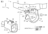
- FIG. 3 is an exploded perspective view showing a rail-shaped holding portion and a band-shaped holding portion of the connector bracket.
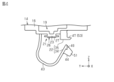
- FIG. 4 is a rear view of the connector bracket.
- FIG. 5 is a front perspective view of the connector bracket before the connector is attached.
- FIG. 6 is a rear perspective view of the connector bracket before the connector is attached.
- FIG. 7 is a side view of the connector bracket.
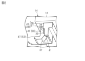
- FIG. 8 is a perspective view of a restrictor.
- FIG. 9 is a procedure diagram for attaching the connector.
- FIG. 10 is a procedure diagram for attaching the connector.
- FIG. 11 is a procedure diagram for attaching the connector.
- FIG. 12 is a procedure diagram for attaching the connector.
- a connector bracket according to the present disclosure is configured to hold a connector provided at an end of an electric wire in a bracket body, and includes a band-shaped connector holding portion that surrounds the connector and holds it in the bracket body;
- the engaging portion that engages with the distal end of the connector holding portion closed to hold the connector and the direction in which the connector holding portion is engaged with the engaging portion are defined as the first direction
- the first direction is the first direction.
- a restricting portion that restricts movement of the connector holding portion in a second direction that intersects with the first direction.
- the connector is surrounded by the connector holding portion, and the tip of the connector holding portion is engaged with the engaging portion while closing the connector holding portion from the first direction.
- the connector is held on the bracket body by the connector holding portion.
- movement of the connector holding portion in the second direction is restricted by the restricting portion. . Therefore, it is possible to make it difficult for the connector holding portion to come off from the engaging portion.
- the engaging portion has an opening on one side surface in the second direction.
- the restricting portion is formed at the edge of the opening so as to come into contact with the outer surface of the tip of the connector holding portion, thereby restricting movement of the connector holding portion in one direction in the second direction.
- 1 restricting portion, and a second restricting portion formed in the engaging portion so as to restrict movement of the connector holding portion in the other direction in the second direction.
- the movement of the connector holding portion in one direction in the second direction is restricted by the first restricting portion, and the movement of the connector holding portion in the second direction in the other direction is restricted by the second restricting portion. Therefore, the position of the connector holding portion can be held by the first restricting portion and the second restricting portion so as not to move in both directions of the second direction. Therefore, it is possible to prevent the connector holding portion from moving in the second direction and coming off the engaging portion.
- the connector holding part has, at the tip of the strip-shaped part, a knob provided so as to protrude from the strip-shaped part that supports the connector when closed.
- the opening is provided so as not to interfere with the knob when closing the connector holder.
- the first restricting portion restricts movement of the connector holding portion in one direction in the second direction by contacting the outer side surface of the knob portion.
- the second restricting portion is formed in the engaging portion and restricts movement of the connector holding portion in the other direction in the second direction by coming into contact with an inner side surface of the knob portion.
- the connector holding portion can be easily held by the finger or the like with the knob, so that workability can be improved when the connector holding portion is attached to or detached from the engaging portion. Further, since the movement of the connector holding portion can be restricted by bringing the regulating portion into contact with the knob portion having a large contact surface, it is more advantageous to prevent the connector holding portion from coming off from the engaging portion.
- the restricting portion has a third restricting portion projecting from the engaging portion so as to be positioned on the rear surface of the knob when the connector holding portion is engaged with the engaging portion. According to this configuration, the third restricting portion also restricts the disengagement of the connector holding portion from the engaging portion, so that it is possible to make the connector holding portion more difficult to come off from the engaging portion.
- the first regulating portion has a protrusion capable of regulating the movement of the connector holding portion, and a thinned portion having a smaller width than the protrusion. According to this configuration, the connector holding portion engaged with the engaging portion can be firmly supported by the protrusion of the first restricting portion, thereby further preventing the connector holding portion from coming off from the engaging portion. be advantageous. Further, by providing the first restricting portion with the thinned portion, it is possible to provide a space for arranging fingers when gripping the connector holding portion. Therefore, it is possible to improve workability when attaching and detaching the connector holding portion to and from the engaging portion.
- the restricting portion is elastically deformable by an operation load applied by an operator when attaching and detaching the connector holding portion to and from the engaging portion. According to this configuration, it is possible to attach and detach the connector holding portion to and from the engaging portion while elastically deforming the restricting portion. In this way, since the restricting portion is not too rigid, it does not interfere with attachment and detachment of the connector holding portion. Therefore, it is possible to improve workability in attaching and detaching the connector holding portion.
- At least one of the connector holding portion, the engaging portion, and the restricting portion is integrally formed with the bracket body. This configuration eliminates the need for a structure and an assembly process for assembling the connector holding portion, the engaging portion, and the restricting portion to the bracket body.
- the connector holding portion supports a portion of the connector to which a mating connector is connected. According to this configuration, the portion of the connector that is likely to be subjected to a load is held by the connector holding portion. Therefore, it is possible to make it difficult for the connector to come off from the connector bracket.
- the connector bracket has a rail-shaped holding portion that attaches and holds the connector with a rail structure. According to this configuration, the connector is held by the bracket body not only by the connector holding portion but also by the rail-shaped holding portion, so that the connector can be held by the bracket body at a plurality of positions. Therefore, it becomes possible to make it more difficult for the connector to come off from the connector bracket.
- the connector bracket when the connector is attached to the rail-shaped holding portion along the guide rail of the rail structure, a projection formed on one of the connector and the bracket body is hooked to the other. is provided with a lock mechanism for fixing the connector to the bracket body. According to this configuration, the state in which the connector is held by the rail-shaped holding portion can be maintained by the lock mechanism. Therefore, it becomes possible to make it more difficult for the connector to come off from the connector bracket.
- the rail-shaped holding part holds the connector on the first surface of the connector.
- the connector holding portion holds the connector on a second surface opposite to the first surface of the connector.
- the rail-shaped holding portion and the connector holding portion are arranged at positions near one end and near the other end of the connector in the second direction, respectively. According to this configuration, since the connector is held by the bracket body at both ends in the insertion/removal direction of the connector, it is possible to support the connector in a well-balanced manner. Therefore, it becomes possible to make it more difficult for the connector to come off from the connector bracket.
- the bracket body is attached with a second connector connected to a second electric wire different from the first electric wire.
- one connector bracket can hold a plurality of connectors.
- a wire harness includes an electric wire having a connector at its end, and a connector bracket that holds the connector in a bracket body, wherein the connector bracket surrounds the connector from the periphery. a strip-shaped connector holding portion held by the bracket body, an engaging portion engaging with the tip of the closed connector holding portion for holding the connector, and engaging the connector holding portion with the engaging portion. and a restricting portion that restricts movement of the connector holding portion in a second direction that intersects with the first direction, when the direction of movement is defined as a first direction. According to this configuration, it is possible to obtain the same effects as those of the connector bracket described above.
- the wire harness 1 is configured by connecting a plurality of electric wires 3 .
- Each electric wire 3 is electrically connected by connecting connectors 4 provided at the ends thereof.
- the wires 3 include a first wire 5 and a second wire 6 .
- the first electric wire 5 is, for example, an Ethernet (registered trademark) cable that connects devices constituting an in-vehicle network LAN (Local Area Network).
- the second electric wire 6 is, for example, a group of electric wires for electrically connecting an in-vehicle device.
- the two first wires 5 are electrically connected by fitting a first connector 10, which is the connector 4 of one of the first wires 5, and a mating connector 11, which is the connector 4 of the other first wire 5.
- the two second wires 6 are electrically connected by fitting a second connector 12, which is the connector 4 of one of the second wires 6, with a mating connector 13, which is the connector 4 of the other second wire 6.
- the number of mating connectors 13 of the second electric wire 6 is not limited to two, and may be, for example, one or three or more.
- the connector 4 is attached to the vehicle body 15 via the connector bracket 14 .
- Only one connector bracket 14 may be provided in the vehicle 2, or a plurality of connector brackets 14 may be provided.
- a vehicle body 15 to which the connector bracket 14 is attached is, for example, a vehicle body wall portion forming a driver's seat.
- a known structure is appropriately used as a fixing structure for attaching the connector bracket 14 to the vehicle body 15 .
- the connector bracket 14 has a bracket body 16 as an attachment portion to the vehicle body 15 .
- the bracket body 16 holds, for example, the second connector 12 connected to the second electric wire 6 . In this manner, the second connector 12 is attached and held to the bracket body 16 itself.
- the bracket body 16 is formed, for example, in a shape in which two opposing side portions are opened, and the second connectors 12 are accommodated side by side inside the openings.
- the connector bracket 14 has a holder portion 19 that holds the first connector 10 connected to the first electric wire 5 .
- the holder portion 19 is held on the outer surface, which may be the bottom surface of the bracket body 16, for example.
- the first connector 10 is attached and fixed to the bracket body 16 via the holder portion 19 .
- the connector bracket 14 (holder portion 19) includes a rail-shaped holding portion 21 that attaches and holds the first connector 10 by means of a rail structure, and a rail-shaped holding portion 21 that cooperates with the rail-shaped holding portion 21 to hold the first connector. and a band-like holding portion 22 for holding the 1 connector 10 .
- the rail-shaped holding portion 21 holds the first connector 10 to the bracket main body 16 by the unevenness of the rail structure.
- the band-like holding portion 22 has a band structure that holds the first connector 10 to the bracket main body 16 by band binding. In this manner, the connector bracket 14 holds the first connector 10 at two locations, the rail-shaped holding portion 21 and the band-shaped holding portion 22 .
- the rail-shaped holding portion 21 has a guide rail 23 (see FIG. 4, etc.) extending in the linear sliding direction of the first connector 10 (the X-axis direction shown in FIG. 4, etc.).
- a moving rail 24 (see FIG. 3) of the first connector 10 that moves along the guide rail 23 is inserted into the guide rail 23 .
- the guide rails 23 are arranged on the outer surface, which may be the bottom surface of the bracket body 16 .
- the guide rail 23 can be, for example, a T-shaped rail.
- the travel rail 24 is located on the outer surface, which may be the top surface of the first connector 10 .
- the moving rails 24 of the first connector 10 are inserted into the guide rails 23 of the bracket body 16, and the first connector 10 is moved in the depth direction (-X in FIG. 3). axial direction). Thereby, the first connector 10 is held by the bracket body 16 by the rail-shaped holding portion 21 . Further, when removing the first connector 10 from the rail-shaped holding portion 21, the first connector 10 is slid in the opposite depth direction (the +X-axis direction in FIG. 3, etc.).
- the connector bracket 14 (holder portion 19) holds the first connector 10 when attaching the first connector 10 to the rail-shaped holding portion 21 along the guide rail 23 of the rail structure.
- a lock mechanism 26 for fixing to the bracket body 16.
- the lock mechanism 26 fixes the first connector 10 to the bracket body 16 by, for example, hooking a projection 27 formed on one of the first connector 10 and the bracket body 16 to the other.
- the locking mechanism 26 engages a projection 27 provided on the bracket main body 16 with a latching projection 28 provided on the first connector 10 , thereby allowing the first connector 10 to slide along the guide rail 23 . lock movement.
- the protrusion 27 is arranged at the end of the guide rail 23 and formed in a shape protruding along the linear slide direction (the X-axis direction shown in FIG. 3, etc.) of the rail structure.
- the protrusion 27 has a plate-like main body 29 and a claw portion 30 arranged at the tip of the main body 29 .
- the main body 29 is provided with a concave portion 31 with which the locking projection 28 is engaged.
- the latching protrusion 28 is arranged on the upper surface of the first connector 10 .
- the lock mechanism 26 when the first connector 10 is fully inserted into the guide rail 23, the locking protrusion 28 of the first connector 10 enters the concave portion 31 of the projection 27, and the claw portion 30 engages the locking protrusion 28. Get caught. Thus, the first connector 10 attached to the guide rail 23 is locked to the bracket body 16 by the locking mechanism 26 being locked.
- the connector bracket 14 (band-shaped holding portion 22 ) has a connector holding portion 34 and an engaging portion 35 .
- the connector holding portion 34 has, for example, a strip shape, and surrounds the first connector 10 to hold it on the bracket body 16 .
- the band-shaped holding portion 22 holds the first connector 10 to the bracket body 16 with a band structure that surrounds the first connector 10 with the band-shaped connector holding portion 34 .
- the connector holding portion 34 is integrally formed with the bracket body 16 .
- the connector holding portion 34 supports a portion of the first connector 10 to which the mating connector 11 is connected, specifically, a tip portion of the first connector 10 .
- the engaging portion 35 has an insertion hole 37 at the bottom for passing the tip of the connector holding portion 34 therethrough.
- the engaging portion 35 has an opening portion 39 on a side surface 38 on the pulling side in the direction (the X-axis direction in FIG. 5 etc.) in which the first connector 10 is inserted into and removed from the rail-shaped holding portion 21 .
- the engaging portion 35 engages with the tip of the closed connector holding portion 34 to hold the first connector 10 .
- the engaging portion 35 has a claw fixing portion 41 capable of engaging a claw portion 40 (see FIG. 6 and the like) provided at the tip of the connector holding portion 34 .
- the connector holding portion 34 is in an open state when the claw portion 40 is not engaged with the claw fixing portion 41 , and is in a closed state when the claw portion 40 is engaged with the claw fixing portion 41 .
- the engaging portion 35 is formed integrally with the bracket body 16 .
- the connector holding portion 34 has a band-shaped portion 43 that supports the first connector 10 when closed, and a knob portion 44 that protrudes from the band-shaped portion 43 .
- the knob 44 is provided, for example, at the tip of the band-shaped portion 43 .
- the knob portion 44 is a portion held by the operator's fingers when attaching or detaching the connector holding portion 34 to or from the engaging portion 35 .
- the knob portion 44 is, for example, a wide projecting piece.
- the opening 39 is provided so that the knob 44 does not interfere when the connector holding portion 34 is closed.
- the direction in which the connector holding portion 34 is engaged with the engaging portion 35 is the operation direction from below (hereinafter referred to as the first direction K1).
- the first direction K1 the direction in which the connector holding portion 34 is engaged with the engaging portion 35
- the claw portion 40 at the tip of the connector holding portion 34 and the claw fixing portion 41 are fixed.
- movement is restricted.
- the connector holding portion 34 is closed from below (the first direction K1)
- the claw portion 40 at the tip is fixed to the claw fixing portion 41 of the engaging portion 35.
- the connector holding portion 34 becomes difficult to move in the vertical direction.
- the connector bracket 14 (holder portion 19) restricts movement of the connector holding portion 34 in a second direction K2 (see FIG. 7) that intersects with the first direction K1. It has a regulation part 47 .
- the restricting portion 47 is formed to be elastically deformable by an operation load applied by an operator when attaching and detaching the connector holding portion 34 to and from the engaging portion 35 .
- the restricting portion 47 is formed integrally with the bracket body 16 .
- the second direction K2 is, for example, the direction in which the first connector 10 is slid along the guide rails 23 of the rail-shaped holding portion 21 .
- the restricting portion 47 includes a first restricting portion 49 formed at the edge of the opening 39 so as to come into contact with the outer surface 48 of the tip of the connector holding portion 34, and the first restricting portion 49. includes a second restricting portion 50 that restricts movement of the connector holding portion 34 in the opposite direction.
- the first restricting portion 49 restricts the movement of the connector holding portion 34 in one of the second directions K2 (the arrow K2A direction in FIG. 7) by coming into contact with the outer surface 48 of the knob portion 44 .
- the second restricting portion 50 is formed on the engaging portion 35 and contacts the inner side surface 51 of the knob portion 44 to move the connector holding portion 34 in the other second direction K2 (the arrow K2B direction in FIG. 7). regulate the movement of
- the restricting portion 47 has a third restricting portion 53 projecting from the engaging portion 35 so as to be located on the rear surface of the knob portion 44 when the connector holding portion 34 is engaged with the engaging portion 35 .
- the third restricting portion 53 prevents the knob portion 44 from being pushed in a direction that releases the closed state of the connector holding portion 34 .
- the third restricting portion 53 is a portion formed by making a part of the engaging portion 35 thick and protruding.
- the first restricting portion 49 has a protrusion 56 capable of restricting the movement of the first connector 10 and a thinned portion 57 having a smaller width than the protrusion 56 .
- the protrusion 56 is, for example, a wall protruding so as to partially close the opening 39 .
- the cutout portion 57 provides, for example, a working space when an operator attaches and detaches the connector holding portion 34 to and from the engaging portion 35 . It should be noted that the cutout portion 57 can regulate the movement of the first connector 10 by, for example, protruding a predetermined amount from the end edge toward the opening portion 39 side.
- the rail-shaped holding portion 21 holds the first connector 10 on the first surface 60 of the first connector 10 .
- the first surface 60 is, for example, the top surface of the first connector 10 .
- the connector holding portion 34 holds the first connector 10 on the second surface 61 that is the opposite surface of the first surface 60 of the first connector 10 .
- the second surface 61 is, for example, the bottom surface of the first connector 10 .
- the rail-shaped holding portion 21 and the connector holding portion 34 are arranged at positions near one end and near the other end of the first connector 10 in the second direction K2, respectively.
- the rail-shaped holding portion 21 and the connector holding portion 34 are arranged in the bracket main body 16 in the insertion/removal direction of the first connector 10 (the X-axis direction in FIG. 7), which can be the linear sliding direction of the first connector 10 .
- the rail-shaped holding portion 21 and the connector holding portion 34 are arranged at both ends separated from each other in the inserting/removing direction of the first connector 10 (the X-axis direction in FIG. 7).
- the first connector 10 when attaching the first connector 10 to the connector bracket 14, first, the first connector 10 is inserted into the band-shaped holding portion 22 in which the connector holding portion 34 is not in the closed state. That is, the first connector 10 is inserted in the direction of arrow A in FIG.
- the first connector 10 is attached to the rail-shaped holding portion 21 of the connector bracket 14 .
- the moving rail 24 of the first connector 10 is moved forward by pulling the first connector 10 inserted into the connector holding portion 34 in the open state (in the direction of the arrow B in the figure). It is inserted into the guide rail 23 of the shape holding part 21 .
- the moving rail 24 of the first connector 10 is fully inserted into the guide rail 23 of the rail-shaped holding portion 21, and then further pushed in the direction of arrow C in the same figure with a finger or the like.
- the first connector 10 is fixed to the rail-shaped holding portion 21 by the locking mechanism 26 . That is, when the first connector 10 is fully inserted into the guide rails 23 of the connector bracket 14, the protrusions 27 of the bracket body 16 are caught by the latching protrusions 28 of the first connector 10, thereby being locked.
- the connector holding portion 34 further holds the first connector 10 .
- the claw portion 40 at the tip of the connector holding portion 34 is inserted into the insertion hole 37 of the engaging portion 35 from below (the first direction indicated by "K1"), and then the claw portion 40 is inserted into the engaging portion 35. engages with the pawl fixing portion 41 of the .
- the connector bracket 14 is packed and shipped to the market with the connector holding portion 34 engaged with the engaging portion 35 . Therefore, if a load is applied to the connector holding portion 34 in the releasing direction when the connector bracket 14 is packed or taken out of the box, the connector holding portion 34 will unintentionally come off the engaging portion 35 . there is a possibility. If the connector holding portion 34 is disengaged from the engaging portion 35, unintended deformation of the connector holding portion 34 may occur. I want to wake up
- the position of the connector holding portion 34 is regulated by the regulating portion 47, so that the connector holding portion 34 remains engaged with the engaging portion 35. easy. Therefore, it is possible to make it difficult for the connector holding portion 34 to unintentionally come off from the engaging portion 35 .
- the connector bracket 14 holds the first connector 10 provided at the end of the first electric wire 5 to the bracket body 16 .
- the connector bracket 14 includes a strip-shaped connector holding portion 34 , an engaging portion 35 and a restricting portion 47 .
- the connector holding portion 34 surrounds the first connector 10 and holds it on the bracket body 16 .
- the engaging portion 35 engages with the tip of the closed connector holding portion 34 to hold the first connector 10 .
- the restricting portion 47 prevents movement of the connector holding portion 34 in a second direction K2 that intersects with the first direction K1. regulate.
- the first connector 10 is surrounded by the connector holding portion 34, and the tip of the connector holding portion 34 is engaged with the engaging portion 35 while closing the connector holding portion 34 from the first direction K1. do.
- the first connector 10 is held on the bracket body 16 by the connector holding portion 34 .
- the connector holding portion 34 will not move in the second direction K2. It is regulated by the regulating portion 47 . Therefore, it is possible to make it difficult for the connector holding portion 34 to come off from the engaging portion 35 .
- the engaging portion 35 has an opening 39 on one side surface 38 in the second direction K2.
- the restricting portion 47 has a first restricting portion 49 and a second restricting portion 50 .
- the first restricting portion 49 is formed at the edge of the opening 39 so as to come into contact with the outer surface 48 of the tip of the connector holding portion 34, thereby restricting the movement of the connector holding portion 34 in one direction in the second direction K2. regulate.
- the second restricting portion 50 is formed in the engaging portion 35 so as to restrict movement of the connector holding portion 34 in the other second direction K2.
- the movement of the connector holding portion 34 in one direction (the arrow K2A direction in FIG. 7) in the second direction K2 is restricted by the first restricting portion 49, and the movement of the connector holding portion 34 in the second direction K2 in the other direction is restricted. Movement in the direction of arrow K2B in FIG. 7 is restricted by the second restricting portion 50 . Therefore, the connector holding portion 34 can be position-held by the first restricting portion 49 and the second restricting portion 50 so as not to move in both directions of the second direction K2. Therefore, it is possible to prevent the connector holding portion 34 from moving in the second direction K ⁇ b>2 and coming off the engaging portion 35 .
- the connector holding part 34 has a knob part 44 at the tip of the band-shaped part 43 that protrudes from the band-shaped part 43 that supports the first connector 10 when closed.
- the opening 39 is provided so that the knob 44 does not interfere when the connector holding portion 34 is closed.
- the first restricting portion 49 restricts movement of the connector holding portion 34 in one direction in the second direction K2 by coming into contact with the outer surface 48 of the knob portion 44 .
- the second restricting portion 50 is formed on the engaging portion 35 and restricts movement of the connector holding portion 34 in the other second direction K2 by coming into contact with the inner side surface 51 of the knob portion 44 .
- the connector holding portion 34 can be easily held by the finger or the like with the knob portion 44, so that workability when attaching and detaching the connector holding portion 34 to and from the engaging portion 35 can be improved.
- the restricting portion 47 has a third restricting portion 53 projecting from the engaging portion 35 so as to be positioned on the rear surface of the knob portion 44 when the connector holding portion 34 is engaged with the engaging portion 35 .
- the third restricting portion 53 also restricts the disengagement of the connector holding portion 34 from the engaging portion 35 .
- the first restricting portion 49 has a protrusion 56 capable of restricting the movement of the connector holding portion 34 and a thinning portion 57 having a smaller width than the protrusion 56 . According to this configuration, the connector holding portion 34 engaged with the engaging portion 35 can be firmly supported by the projecting portion 56 of the first restricting portion 49 . It is more advantageous for preventing 34 from coming off. Further, by providing the thinned portion 57 in the first restricting portion 49, it becomes possible to provide a space for arranging fingers when gripping the connector holding portion 34. As shown in FIG. Therefore, it is possible to improve workability when attaching and detaching the connector holding portion 34 to and from the engaging portion 35 .
- the regulating portion 47 is elastically deformable by an operation load applied by the operator when attaching and detaching the connector holding portion 34 to and from the engaging portion 35 . According to this configuration, it is possible to attach and detach the connector holding portion 34 to and from the engaging portion 35 while elastically deforming the restricting portion 47 . As described above, since the restricting portion 47 is not too rigid, it does not interfere with attachment and detachment of the connector holding portion 34 . Therefore, the workability of attaching and detaching the connector holding portion 34 can be improved.
- At least one of the connector holding portion 34, the engaging portion 35, and the restricting portion 47 is formed integrally with the bracket body 16. This configuration eliminates the need for a structure and an assembly process for assembling the connector holding portion 34, the engaging portion 35, and the restricting portion 47 to the bracket body 16.
- the connector holding portion 34 supports a portion of the first connector 10 to which the mating connector 11 is connected. According to this configuration, the portion of the first connector 10 to which a load is likely to be applied is held by the connector holding portion 34 . Therefore, the first connector 10 can be made difficult to fall off from the connector bracket 14 .
- the connector bracket 14 has a rail-shaped holding portion 21 that attaches and holds the first connector 10 with a rail structure. According to this configuration, since the first connector 10 is held on the bracket body 16 not only by the connector holding portion 34 but also by the rail-shaped holding portion 21, it is possible to hold the first connector 10 on the bracket body 16 at a plurality of positions. Become. Therefore, it is possible to make the first connector 10 more difficult to come off from the connector bracket 14 .
- the connector bracket 14 has a lock mechanism 26 .
- the lock mechanism 26 engages the protrusion 27 formed on one of the first connector 10 and the bracket body 16 with the other.
- the first connector 10 is fixed to the bracket body 16 by hooking. According to this configuration, the state in which the first connector 10 is held by the rail-shaped holding portion 21 can be maintained by the lock mechanism 26 . Therefore, it is possible to make the first connector 10 more difficult to come off from the connector bracket 14 .
- the rail-shaped holding portion 21 holds the first connector 10 on the first surface 60 of the first connector 10 .
- the connector holding portion 34 holds the first connector 10 on the second surface 61 that is the opposite surface of the first surface 60 of the first connector 10 .
- the rail-shaped holding portion 21 and the connector holding portion 34 are arranged at positions near one end and near the other end of the first connector 10 in the second direction K2, respectively. According to this configuration, since the first connector 10 is held by the bracket body 16 at both ends in the inserting/removing direction of the first connector 10, the first connector 10 can be supported in a well-balanced manner. Therefore, it is possible to make the first connector 10 more difficult to come off from the connector bracket 14 .
- a second connector 12 connected to a second electric wire 6 different from the first electric wire 5 is attached to the bracket body 16 .
- one connector bracket 14 can hold a plurality of connectors 4 .
- this embodiment can be changed and implemented as follows. This embodiment and the following modified examples can be implemented in combination with each other within a technically consistent range.
- the restricting portion 47 may be a member having a U-shaped cross section. In this case, the position is maintained by inserting the connector holding portion 34 inside the U-shape.
- the 1st control part 49 is good also as a shape which has only the protrusion 56, for example.
- the first restricting portion 49 may have a shape that covers most of the opening 39 .
- the wall which comprises the insertion hole 37 of the engaging part 35 may be sufficient as the 2nd control part 50.
- the 3rd control part 53 may be abbreviate
- the knob portion 44 may be provided at a portion other than the tip of the connector holding portion 34 instead of the tip.
- the connector holding portion 34 may have a shape in which the knob portion 44 is omitted.
- the guide rail 23 may be provided on the first connector 10 and the moving rail 24 may be provided on the connector bracket 14 .
- the rail structure of the rail-shaped holding portion 21 may be any structure as long as the first connector 10 can be attached and detached along the rail portion.
- the band-shaped holding part 22 may be placed anywhere as long as it can support the first connector 10 .
- the first surface 60 on which the rail-shaped holding portion 21 is arranged is not limited to the upper surface of the first connector 10, and may be changed to the side portion of the first connector 10, for example.
- the second surface 61 on which the band-shaped holding portion 22 is arranged is not limited to the bottom surface of the first connector 10, and may be changed to the top surface or side portion of the first connector 10, for example.
- the rail-shaped holding part 21 and the band-shaped holding part 22 may be arranged at the same end of the first connector 10 .
- the rail-shaped holding portion 21 may be omitted.
- the lock mechanism 26 may be modified into various structures as long as the first connector 10 inserted into the guide rail 23 can be fixed to the bracket body 16 .
- the portion of the connector bracket 14 that holds the second connector 12 may be omitted.
- the wire harness 1 may be an electric wire group in which a plurality of electric wires 3 are bundled.
- the wire harness 1 may be an electric wire member whose periphery is covered with a covering material.
- the wire harness 1 is not limited to in-vehicle use, and may be used in other devices and devices.
- the proximal end of the connector holding portion 34 (band-shaped portion 43 ) of the illustrated embodiment may be integrally formed on the bottom surface of the bracket body 16 .
- the engaging portion 35 is provided on the bottom surface of the bracket body 16, and is perpendicular to the first direction K1 (Z-axis direction) and the second direction K2 (X-axis direction).
- a third side wall connecting the ends of the side (in the direction of arrow K2B in FIG. 7) to each other, and the insertion hole 37 is inserted into the bottom of the engaging portion 35 by the first side wall, the second side wall and the third side wall. may be formed.
- the restricting portion 47 extends from the end of the second side wall on one side in the second direction K2 (X-axis direction) (the arrow K2A direction in FIG. 7) toward the first side wall. It may protrude along the third direction (Y-axis direction) and face the end surface (side surface 38) of the first side wall on one side in the second direction K2 in the second direction K2.
- the distance in the second direction K2 between the restricting portion 47 and the side surface 38 may be shorter than the width of the claw portion 40 in the second direction K2.
- the knob portion 44 is located at the end of the tip of the connector holding portion 34 (strip-shaped portion 43) in the second direction K2 (X-axis direction) on one side (arrow K2A direction in FIG. 7). may protrude from the portion along the third direction (Y-axis direction).
- the length of the knob 44 in the third direction may be longer than the distance in the third direction between the first side wall and the second side wall.
- the thickness of the knob portion 44 in the second direction K2 (X-axis direction) may be shorter than the distance in the second direction K2 between the side surface 38 of the first side wall and the restricting portion 47 .
- the knob portion 44 is regulated by the side surface 38 of the first side wall. It may be sandwiched between the portion 47 and the portion 47 .
Landscapes
- Engineering & Computer Science (AREA)
- Mechanical Engineering (AREA)
- Architecture (AREA)
- Civil Engineering (AREA)
- Structural Engineering (AREA)
- Details Of Connecting Devices For Male And Female Coupling (AREA)
- Connector Housings Or Holding Contact Members (AREA)
Abstract
Description
[1]本開示のコネクタブラケットは、電線の端部に設けられたコネクタをブラケット本体に保持する構成であって、前記コネクタを周囲から囲んで前記ブラケット本体に保持する帯状のコネクタ保持部と、前記コネクタを保持するために閉じた前記コネクタ保持部の先端と係合する係合部と、前記コネクタ保持部を前記係合部に係合するときの方向を第1方向とした場合、前記第1方向と交差する第2方向への前記コネクタ保持部の動きを規制する規制部とを備えている。
本開示の具体例を、以下に図面を参照しつつ説明する。なお、本発明はこれらの例示に限定されるものではなく、特許請求の範囲によって示され、特許請求の範囲と均等の意味および範囲内でのすべての変更が含まれることが意図される。各図面では、説明の便宜上、構成の一部を誇張又は簡略化して示す場合がある。また、各部分の寸法比率についても、実際とは異なる場合がある。
図1に示すように、車載用のワイヤハーネス1は、車両2に設けられた電装品同士を電気接続する。ワイヤハーネス1は、複数の電線3を繋いで構成されている。各電線3は、端部に設けられたコネクタ4同士を繋ぐことにより、電気接続される。例えば、電線3は、第1電線5及び第2電線6を含む。第1電線5は、例えば、車内ネットワークLAN(Local Area Network)を構成する機器を繋ぐイーサネット(登録商標)ケーブルである。第2電線6は、例えば、車載装置を電気接続する電線群である。
図2及び図3に示すように、コネクタブラケット14は、第1電線5に接続された第1コネクタ10を保持するホルダ部19を備えている。ホルダ部19は、例えば、ブラケット本体16の底面であり得る外面に保持されている。このように、第1コネクタ10は、ホルダ部19を介してブラケット本体16に取り付け固定される。
図3~図6に示す通り、レール状保持部21は、第1コネクタ10の直線的スライド方向(図4等に示すX軸方向)に延びる案内レール23(図4等参照)を有する。案内レール23には、案内レール23を移動する第1コネクタ10の移動レール24(図3参照)が挿し込まれる。案内レール23は、ブラケット本体16の底面であり得る外面に配置されている。案内レール23は、例えば、T状レールであり得る。移動レール24は、第1コネクタ10の上面であり得る外面に配置されている。
図3、図5及び図6に示す通り、コネクタブラケット14(ホルダ部19)は、レール構造の案内レール23に沿って第1コネクタ10をレール状保持部21に取り付けるときに、第1コネクタ10をブラケット本体16に固定するロック機構26を備えている。ロック機構26は、例えば、第1コネクタ10及びブラケット本体16の一方に形成した突起27を、これらの他方に引っ掛けることにより、第1コネクタ10をブラケット本体16に固定する。
図2等に示す通り、コネクタブラケット14(バンド状保持部22)は、コネクタ保持部34及び係合部35を有する。コネクタ保持部34は、例えば、帯状をなすとともに、第1コネクタ10を周囲から囲んでブラケット本体16に保持する。このように、バンド状保持部22は、帯状のコネクタ保持部34で第1コネクタ10を周囲から囲むバンド構造によって、第1コネクタ10をブラケット本体16に保持する。コネクタ保持部34は、ブラケット本体16に一体形成されている。コネクタ保持部34は、第1コネクタ10において相手コネクタ11が接続される部位、具体的には、第1コネクタ10の先端部位を支持する。
図2、図7及び図8に示すように、コネクタブラケット14(ホルダ部19)は、第1方向K1と交差する第2方向K2(図7参照)へのコネクタ保持部34の動きを規制する規制部47を有する。規制部47は、コネクタ保持部34を係合部35に着脱する際に作業者から付与される操作荷重によって弾性変形可能に形成されている。規制部47は、ブラケット本体16に一体形成されている。第2方向K2は、例えば、第1コネクタ10をレール状保持部21の案内レール23に沿ってスライド移動させるときの方向である。
図7に示す通り、レール状保持部21は、第1コネクタ10の第1面60で第1コネクタ10を保持する。第1面60は、例えば、第1コネクタ10の上面である。コネクタ保持部34は、第1コネクタ10において第1面60の反対側の面である第2面61で第1コネクタ10を保持する。第2面61は、例えば、第1コネクタ10の底面である。
次に、本実施形態のコネクタブラケット14(ワイヤハーネス1)の作用について説明する。
上記実施形態のコネクタブラケット14(ワイヤハーネス1)によれば、以下のような効果を得ることができる。
なお、本実施形態は、以下のように変更して実施することができる。本実施形態及び以下の変更例は、技術的に矛盾しない範囲で互いに組み合わせて実施することができる。
・第1規制部49は、例えば、突部56のみを有する形状としてもよい。
・第2規制部50は、係合部35の挿込穴37を構成する壁でもよい。
・第3規制部53は、省略されてもよい。
・コネクタ保持部34は、摘み部44が省略された形状でもよい。
・レール状保持部21のレール構造は、レール部位に沿って第1コネクタ10を着脱できる構造であればよい。
・レール状保持部21が配置される第1面60は、第1コネクタ10の上面に限らず、例えば、第1コネクタ10の側部などに変更してもよい。
・レール状保持部21及びバンド状保持部22は、第1コネクタ10の同じ端部に配置されてもよい。
・ロック機構26は、案内レール23に挿し込まれた第1コネクタ10をブラケット本体16に固定できる構造であれば、種々の構造に変更してもよい。
・ワイヤハーネス1は、複数の電線3を束ねた電線群でもよい。また、ワイヤハーネス1は、周囲が被覆材に覆われた電線部材でもよい。
・図示した実施形態のコネクタ保持部34(帯状部43)の基端が、ブラケット本体16の底面に一体形成されてよい。
3 電線
4 コネクタ
5 第1電線
6 第2電線
10 第1コネクタ
11 相手コネクタ
12 第2コネクタ
13 相手コネクタ
14 コネクタブラケット
15 車体
16 ブラケット本体
19 ホルダ部
21 レール状保持部
22 バンド状保持部
23 案内レール
24 移動レール
26 ロック機構
27 突起
28 掛止突
29 本体
30 爪部
31 凹部
34 コネクタ保持部
35 係合部
37 挿込穴
38 側面
39 開口部
40 爪部
41 爪固定部
43 帯状部
44 摘み部
47 規制部
48 外側面
49 第1規制部
50 第2規制部
51 内側面
53 第3規制部
56 突部
57 肉取り部
60 第1面
61 第2面
62 端部
63 端部
K1 第1方向
K2 第2方向
Claims (14)
- 電線の端部に設けられたコネクタをブラケット本体に保持するコネクタブラケットであって、
前記コネクタを周囲から囲んで前記ブラケット本体に保持する帯状のコネクタ保持部と、
前記コネクタを保持するために閉じた前記コネクタ保持部の先端と係合する係合部と、
前記コネクタ保持部を前記係合部に係合するときの方向を第1方向とした場合、前記第1方向と交差する第2方向への前記コネクタ保持部の動きを規制する規制部と
を備えているコネクタブラケット。 - 前記係合部は、前記第2方向の片方の側面に開口部を有し、
前記規制部は、前記コネクタ保持部の先端の外側面に接触するように前記開口部の端縁に形成されることにより、前記コネクタ保持部の前記第2方向の一方への動きを規制する第1規制部と、前記コネクタ保持部の前記第2方向の他方への動きを規制するように前記係合部に形成された第2規制部とを含む
請求項1に記載のコネクタブラケット。 - 前記コネクタ保持部は、閉じたときに前記コネクタを支える帯状部から突設するように設けられた摘み部を前記帯状部の先端に有し、
前記開口部は、前記コネクタ保持部を閉じるときに前記摘み部を干渉させないために設けられ、
前記第1規制部は、前記摘み部の前記外側面に接触することによって、前記コネクタ保持部の前記第2方向の一方への動きを規制し、
前記第2規制部は、前記係合部に形成されるとともに、前記摘み部の内側面に接触することによって、前記コネクタ保持部の前記第2方向の他方への動きを規制する
請求項2に記載のコネクタブラケット。 - 前記規制部は、前記コネクタ保持部を前記係合部に係合したときに前記摘み部の背面に位置するように前記係合部から突設された第3規制部を有する
請求項3に記載のコネクタブラケット。 - 前記第1規制部は、前記コネクタ保持部の動きを規制可能な突部と、前記突部よりも幅を小さくした肉取り部とを有する
請求項2から請求項4のいずれか一項に記載のコネクタブラケット。 - 前記規制部は、前記コネクタ保持部を前記係合部に着脱する際に作業者から付与される操作荷重によって弾性変形可能に形成されている
請求項1から請求項5のいずれか一項に記載のコネクタブラケット。 - 前記コネクタ保持部、前記係合部、及び前記規制部の少なくとも1つは、前記ブラケット本体に一体形成されている
請求項1から請求項6のいずれか一項に記載のコネクタブラケット。 - 前記コネクタ保持部は、前記コネクタにおいて相手コネクタが接続される部位を支持する
請求項1から請求項7のいずれか一項に記載のコネクタブラケット。 - 前記コネクタをレール構造によって取り付けて保持するレール状保持部を備えている
請求項1から請求項8のいずれか一項に記載のコネクタブラケット。 - 前記レール構造の案内レールに沿って前記コネクタを前記レール状保持部に取り付けるときに、前記コネクタ及び前記ブラケット本体の一方に形成した突起を、これらの他方に引っ掛けることにより、前記コネクタを前記ブラケット本体に固定するロック機構を備えている
請求項9に記載のコネクタブラケット。 - 前記レール状保持部は、前記コネクタの第1面で前記コネクタを保持し、
前記コネクタ保持部は、前記コネクタにおいて前記第1面の反対側の面である第2面で前記コネクタを保持する
請求項9又は請求項10に記載のコネクタブラケット。 - 前記レール状保持部及び前記コネクタ保持部は、前記第2方向における前記コネクタの一方の端寄りの位置と他方の端寄りの位置とにそれぞれ配置されている
請求項9から請求項11のいずれか一項に記載のコネクタブラケット。 - 前記電線を第1電線とし、前記コネクタを第1コネクタとした場合、前記ブラケット本体には、前記第1電線とは別の第2電線に接続された第2コネクタが取り付けられている請求項1から請求項12のいずれか一項に記載のコネクタブラケット。
- コネクタを端部に有する電線と、前記コネクタをブラケット本体に保持するコネクタブラケットとを備えているワイヤハーネスであって、
前記コネクタブラケットは、
前記コネクタを周囲から囲んで前記ブラケット本体に保持する帯状のコネクタ保持部と、
前記コネクタを保持するために閉じた前記コネクタ保持部の先端と係合する係合部と、
前記コネクタ保持部を前記係合部に係合するときの方向を第1方向とした場合、前記第1方向と交差する第2方向への前記コネクタ保持部の動きを規制する規制部と
を備えているワイヤハーネス。
Priority Applications (2)
| Application Number | Priority Date | Filing Date | Title |
|---|---|---|---|
| US18/729,883 US20250105563A1 (en) | 2022-01-25 | 2023-01-06 | Connector bracket and wiring harness |
| CN202380017646.8A CN118575375A (zh) | 2022-01-25 | 2023-01-06 | 连接器支架及线束 |
Applications Claiming Priority (2)
| Application Number | Priority Date | Filing Date | Title |
|---|---|---|---|
| JP2022009271A JP7711598B2 (ja) | 2022-01-25 | 2022-01-25 | コネクタブラケット及びワイヤハーネス |
| JP2022-009271 | 2022-01-25 |
Publications (1)
| Publication Number | Publication Date |
|---|---|
| WO2023145409A1 true WO2023145409A1 (ja) | 2023-08-03 |
Family
ID=87471220
Family Applications (1)
| Application Number | Title | Priority Date | Filing Date |
|---|---|---|---|
| PCT/JP2023/000216 Ceased WO2023145409A1 (ja) | 2022-01-25 | 2023-01-06 | コネクタブラケット及びワイヤハーネス |
Country Status (4)
| Country | Link |
|---|---|
| US (1) | US20250105563A1 (ja) |
| JP (2) | JP7711598B2 (ja) |
| CN (1) | CN118575375A (ja) |
| WO (1) | WO2023145409A1 (ja) |
Citations (7)
| Publication number | Priority date | Publication date | Assignee | Title |
|---|---|---|---|---|
| JPS492789U (ja) * | 1972-04-11 | 1974-01-11 | ||
| US20060046557A1 (en) * | 2004-08-26 | 2006-03-02 | Pulizzi Peter S | Connector restraint device |
| JP2010146888A (ja) * | 2008-12-19 | 2010-07-01 | Ohm Denki Kk | コネクタ用固定具 |
| JP2011229232A (ja) * | 2010-04-16 | 2011-11-10 | Sumitomo Wiring Syst Ltd | ワイヤハーネス |
| JP2014209409A (ja) * | 2013-04-16 | 2014-11-06 | 住友電装株式会社 | ワイヤハーネスおよびコネクタ部材 |
| JP2019110119A (ja) * | 2017-12-18 | 2019-07-04 | 廣達電腦股▲ふん▼有限公司 | 電子システム及びケーブルの固定用の固持装置 |
| JP2020057601A (ja) * | 2018-09-28 | 2020-04-09 | 矢崎総業株式会社 | ワイヤハーネス |
Family Cites Families (5)
| Publication number | Priority date | Publication date | Assignee | Title |
|---|---|---|---|---|
| JPS5920776Y2 (ja) * | 1981-10-28 | 1984-06-16 | 株式会社フジクラ | 固定用バンド付コネクタ |
| JP2000133389A (ja) * | 1998-10-21 | 2000-05-12 | Sumitomo Wiring Syst Ltd | コネクタ取付用のクランプ |
| JP2002335620A (ja) * | 2001-05-09 | 2002-11-22 | Kitagawa Ind Co Ltd | プラグ保持具 |
| JP5755368B2 (ja) * | 2012-04-24 | 2015-07-29 | 本田技研工業株式会社 | 車両用コンビネーションスイッチアセンブリ |
| JP6597375B2 (ja) * | 2016-02-19 | 2019-10-30 | 株式会社オートネットワーク技術研究所 | 配線構造 |
-
2022
- 2022-01-25 JP JP2022009271A patent/JP7711598B2/ja active Active
-
2023
- 2023-01-06 CN CN202380017646.8A patent/CN118575375A/zh active Pending
- 2023-01-06 WO PCT/JP2023/000216 patent/WO2023145409A1/ja not_active Ceased
- 2023-01-06 US US18/729,883 patent/US20250105563A1/en active Pending
-
2025
- 2025-06-27 JP JP2025108803A patent/JP2025126307A/ja active Pending
Patent Citations (7)
| Publication number | Priority date | Publication date | Assignee | Title |
|---|---|---|---|---|
| JPS492789U (ja) * | 1972-04-11 | 1974-01-11 | ||
| US20060046557A1 (en) * | 2004-08-26 | 2006-03-02 | Pulizzi Peter S | Connector restraint device |
| JP2010146888A (ja) * | 2008-12-19 | 2010-07-01 | Ohm Denki Kk | コネクタ用固定具 |
| JP2011229232A (ja) * | 2010-04-16 | 2011-11-10 | Sumitomo Wiring Syst Ltd | ワイヤハーネス |
| JP2014209409A (ja) * | 2013-04-16 | 2014-11-06 | 住友電装株式会社 | ワイヤハーネスおよびコネクタ部材 |
| JP2019110119A (ja) * | 2017-12-18 | 2019-07-04 | 廣達電腦股▲ふん▼有限公司 | 電子システム及びケーブルの固定用の固持装置 |
| JP2020057601A (ja) * | 2018-09-28 | 2020-04-09 | 矢崎総業株式会社 | ワイヤハーネス |
Also Published As
| Publication number | Publication date |
|---|---|
| JP2025126307A (ja) | 2025-08-28 |
| JP2023108252A (ja) | 2023-08-04 |
| CN118575375A (zh) | 2024-08-30 |
| US20250105563A1 (en) | 2025-03-27 |
| JP7711598B2 (ja) | 2025-07-23 |
Similar Documents
| Publication | Publication Date | Title |
|---|---|---|
| JP4689986B2 (ja) | バンドクランプ | |
| JP5713642B2 (ja) | コネクタユニット | |
| US6217358B1 (en) | Connector coupling structure | |
| KR20180022548A (ko) | 커넥터 어셈블리 | |
| JP2003343526A (ja) | クリップの取付構造 | |
| WO2023145409A1 (ja) | コネクタブラケット及びワイヤハーネス | |
| EP1695850A2 (en) | Bracket Connecting Structure | |
| JP5412997B2 (ja) | 電気接続箱 | |
| CN101227041A (zh) | 连接器的锁定机构 | |
| US20240136752A1 (en) | Connector bracket and wire harness | |
| JP3954369B2 (ja) | 車載用カードホルダ装置 | |
| JP2012190706A (ja) | コネクタ装置 | |
| JP7625991B2 (ja) | プロテクタ | |
| KR200465856Y1 (ko) | 커넥터의 와이어커버 결합구조 | |
| JP3901956B2 (ja) | 補器のブラケット結合構造 | |
| CN114746309A (zh) | 连接器保持体及线束 | |
| JP7722273B2 (ja) | ワイヤハーネス用固定具及びワイヤハーネス | |
| JP4653967B2 (ja) | ワイヤハーネスの保持構造及び該保持構造を備えた電気接続箱 | |
| JP3889576B2 (ja) | ブラケット結合構造 | |
| JP4205569B2 (ja) | ハーネスプロテクタの固定構造およびハーネスプロテクタ | |
| JP2006325283A (ja) | ワイヤハーネス固定用クリップ | |
| JP5085437B2 (ja) | ツーピースクリップ | |
| JP2019061744A (ja) | コネクタ、ハウジング、カバー体、及びコネクタ付ワイヤーハーネス | |
| CN119542836A (zh) | 具有附加锁件的杆锁件电连接器 | |
| JP2018017285A (ja) | 配線部材固定用部品及びプロテクタ付配線部材 |
Legal Events
| Date | Code | Title | Description |
|---|---|---|---|
| 121 | Ep: the epo has been informed by wipo that ep was designated in this application |
Ref document number: 23746626 Country of ref document: EP Kind code of ref document: A1 |
|
| WWE | Wipo information: entry into national phase |
Ref document number: 18729883 Country of ref document: US Ref document number: 202380017646.8 Country of ref document: CN |
|
| NENP | Non-entry into the national phase |
Ref country code: DE |
|
| 122 | Ep: pct application non-entry in european phase |
Ref document number: 23746626 Country of ref document: EP Kind code of ref document: A1 |
|
| WWP | Wipo information: published in national office |
Ref document number: 18729883 Country of ref document: US |