WO2023145279A1 - オートバランサ - Google Patents
オートバランサ Download PDFInfo
- Publication number
- WO2023145279A1 WO2023145279A1 PCT/JP2022/045623 JP2022045623W WO2023145279A1 WO 2023145279 A1 WO2023145279 A1 WO 2023145279A1 JP 2022045623 W JP2022045623 W JP 2022045623W WO 2023145279 A1 WO2023145279 A1 WO 2023145279A1
- Authority
- WO
- WIPO (PCT)
- Prior art keywords
- stator
- balance
- rotor
- outer peripheral
- peripheral surface
- Prior art date
Links
Images


Classifications
-
- G—PHYSICS
- G01—MEASURING; TESTING
- G01M—TESTING STATIC OR DYNAMIC BALANCE OF MACHINES OR STRUCTURES; TESTING OF STRUCTURES OR APPARATUS, NOT OTHERWISE PROVIDED FOR
- G01M1/00—Testing static or dynamic balance of machines or structures
- G01M1/30—Compensating unbalance
- G01M1/36—Compensating unbalance by adjusting position of masses built-in the body to be tested
Definitions
- the present invention relates to an autobalancer that corrects the imbalance of a rotating body.
- a grinding device that grinds a workpiece with a disk-shaped grinding wheel (rotating body) that is rotated at high speed by a spindle.
- the grinding apparatus is provided with an auto balancer capable of automatically correcting the imbalance of the grinding wheel during high-speed rotation (see Patent Document 1).
- the auto balancer has a balance head that is connected to the grinding wheel and rotates integrally with the grinding wheel, and a stator (also called a sender) that transmits the drive power and drive command for the balance head input from the controller to the balance head. , provided.
- the balance head corrects the unbalance of the grinding wheel by moving a plurality of balance weights within the balance head based on drive power and drive commands input from the stator.
- the stator described in Patent Literature 2 includes a transmitter and stator coils capable of wirelessly transmitting drive power and drive commands.
- the stator is arranged to face the front end face of the balance head, which is opposite to the rear end face of the balance head which is connected to the grinding wheel.
- a rotor is provided on the front end surface of the balance head described in Patent Document 2.
- the rotor is provided with rotor coils and a receiving circuit for receiving drive power and drive commands wirelessly transmitted from the stator.
- the driving power and the driving command can be wirelessly transmitted from the stator to the balance head without connecting the stator to the balance head.
- the balance head and stator are arranged in series along the axial direction of a rotating shaft that rotates a rotating body such as a grinding wheel.
- the balance head and the stator are arranged to face each other so as to overlap each other in series in the thickness direction.
- the length of the autobalancer in the axial direction of the rotating shaft is increased (thickness is increased), and it becomes necessary to secure an installation space for the autobalancer within the grinding apparatus.
- the present invention has been made in view of such circumstances, and it is an object of the present invention to provide an autobalancer in which the length of the rotating shaft in the axial direction is shorter than conventional ones.
- An autobalancer for achieving the object of the present invention is a balance head that rotates integrally with the rotating body about the rotation axis of the rotating body, and is an electric balance correction mechanism that corrects imbalance of the rotating body.
- a balance head having a cylindrical outer peripheral surface parallel to the rotation axis and a case for housing a balance correction mechanism;
- a stator having a shape along the circumferential direction of the outer peripheral surface, the stator being electrically connected to a controller of the balance head, and a rotor provided at a position facing the stator on the outer peripheral surface and rotating integrally with the balance head.
- a rotor portion having a shape along the circumferential direction of the outer peripheral surface and electrically connected to the balance correction mechanism; a rotor portion shaped to follow the shape of the rotor electrically connected to the balance correcting mechanism to enable wireless transmission between the stator and the rotor portion.
- the stator can be loosely fitted to the outer peripheral surface of the case of the balance head, and the rotor portion can be provided on the outer peripheral surface of the case.
- the stator is formed in a ring shape along the circumferential direction of the outer peripheral surface and loosely fitted to the outer peripheral surface.
- the rotor portion is formed in a ring shape along the circumferential direction of the outer peripheral surface. This allows wireless transmission between the stator and rotor sections.
- stator and rotor section face each other in the axial direction of the rotating shaft. This allows wireless transmission between the stator and rotor sections.
- the stator wirelessly transmits the driving power and the driving command for the balance head output from the controller to the rotor unit, the rotor receives the driving power and the driving command from the stator, A balance correction mechanism operates based on the drive power and drive command received by the rotor section. Thereby, the drive power and the drive command can be transmitted from the stator to the balance head in a non-contact manner.
- the case is provided with a detection sensor that detects contact of a contacting object with the rotating body, the rotor section wirelessly transmits a detection signal of the detection sensor to the stator, The stator inputs detection signals received from the rotor section to the controller. Thereby, the detection signal can be transmitted from the balance head to the stator in a non-contact manner.
- the present invention can shorten the length of the autobalancer in the axial direction of the rotating shaft.
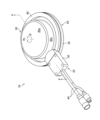
- FIG. 1 is a perspective view of a non-contact balance head and stator
- FIG. 3 is an exploded perspective view of the balance head and stator shown in FIG. 2
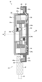
- FIG. 4 is a cross-sectional view of the balance head and stator shown in FIG. 2 taken along line 4-4
- FIG. 5 is an explanatory diagram for explaining the effect of the autobalancer of the present embodiment with respect to the autobalancer of the comparative example
- FIG. 1 is a schematic diagram showing an example in which the autobalancer 16 of the present invention is applied to a grinding device 10.
- the grinding device 10 is used, for example, for grinding a workpiece W, and includes a grinding wheel 12, a spindle 14, and an auto balancer 16.
- the grinding wheel 12 corresponds to the rotating body of the present invention and is shaped like a disc.
- the grinding wheel 12 is held by a spindle 14 so as to be rotatable about a rotating shaft 14a.
- a balance head 20 constituting an auto balancer 16 is connected to the grinding wheel 12 and rotates together with the balance head 20 .
- the spindle 14 incorporates a motor, and rotates the grinding wheel 12 at high speed around a rotating shaft 14a.
- the symbol Ax in the drawing indicates the axial direction of the rotating shaft 14a.
- the symbol ⁇ is the direction around the axis of rotation 14 a , that is, the direction of rotation of grinding wheel 12 and balance head 20 .
- the auto balancer 16 automatically corrects the imbalance of the grinding wheel 12 rotating at high speed.
- the autobalancer 16 includes a non-contact balance head 20 and stator 22 , a vibration sensor 24 and a controller 26 .
- the auto balancer 16 may be provided with a detection sensor for detecting the rotation angle of the balance head 20 (see Patent Document 2 above).
- the balance head 20 is connected to the grinding wheel 12 via an adapter flange 28. As a result, as described above, the grinding wheel 12 and the balance head 20 rotate integrally in the direction ⁇ around the axis.
- the balance head 20 operates based on drive power and drive commands that are non-contactly input from the controller 26 via the stator 22 to correct the unbalance of the grinding wheel 12 during high-speed rotation.
- FIG. 2 is a perspective view of the non-contact balance head 20 and stator 22.
- FIG. FIG. 3 is an exploded perspective view of balance head 20 and stator 22 shown in FIG.
- FIG. 4 is a cross-sectional view of balance head 20 and stator 22 shown in FIG. 2 along line 4--4.
- the balance head 20 includes a case 30, a rotor section 32, a balance correction mechanism 34, an AE sensor 36, and a control board 38.
- the case 30 is formed in a hollow columnar shape parallel to the axial direction Ax.
- the case 30 comprises a disc-shaped front end face 30a and a disc-shaped rear end face 30b which are spaced apart in the axial direction Ax and perpendicular to the axial direction Ax, and a cylindrical outer peripheral face 30c parallel to the axial direction Ax. It is
- the outer peripheral surface 30c connects the peripheral edge portion of the front end surface 30a and the peripheral edge portion of the rear end surface 30b.
- the outer peripheral surface 30c is configured to be divisible in two in the axial direction Ax.
- An electric balance correction mechanism 34 is housed in the space inside the case 30 .
- a control board 38 and an AE sensor 36 are provided in the wall portion forming the rear end face 30b.
- the balance correction mechanism 34 includes two balance weights 34a and two sets of motor drive mechanisms 34b. Each balance weight 34a is held by a different motor driving mechanism 34b so as to be displaceable in the direction ⁇ around the axis about the axial direction Ax. Each motor drive mechanism 34b is composed of, for example, a motor and a plurality of gears. Each motor drive mechanism 34b receives power supply from the control board 38 and displaces each balance weight 34a in the axial direction ⁇ independently of each other. Note that the balance correction mechanism 34 is not particularly limited to the one shown in the drawing, and various known types can be employed.
- the AE sensor 36 is an acoustic emission (AE) sensor and corresponds to the detection sensor of the present invention.
- the AE sensor 36 detects a high-frequency sound generated when the workpiece W, the dresser, or another contact object contacts the grinding wheel 12, and outputs a detection signal of this sound to the control board 38. .
- the rotor portion 32 is provided on the outer peripheral surface 30c and rotates integrally with the balance head 20 in the direction ⁇ around the axis.
- the rotor portion 32 is formed in a shape along the circumferential direction (direction ⁇ around the axis) of the outer peripheral surface 30c, more specifically, in a ring shape (flange shape).
- a rotor coil 32a which is a ring-shaped antenna coil, is provided in the rotor portion 32. As shown in FIG. Although the rotor portion 32 is formed integrally with the case 30 in this embodiment, the rotor portion 32 formed separately from the case 30 may be fixed to the case 30 .
- the rotor coil 32a is electrically connected to the control board 38, and further electrically connected to the balance correction mechanism 34 and the like through the control board 38.
- the rotor coil 32a receives driving power wirelessly transmitted (power transmission) from the stator 22, which will be described later, and a drive command for the balance correction mechanism 34 wirelessly transmitted (information transmission) from the stator 22 as well.
- the rotor coil 32 a wirelessly transmits (information transmits) the detection signal of the AE sensor 36 input from the control board 38 to the stator 22 .
- the control board 38 has a processor such as a CPU (Central Processing Unit), a power receiving circuit, a power transmission circuit, a reception demodulator, a transmission modulator, and the like, and controls the operation of each part of the balance head 20 and power supply to each part. Control. After converting the drive power (AC power) received by the rotor coil 32a into DC power, the control board 38 supplies this drive power to the balance correction mechanism 34, the AE sensor 36, and the like. The control board 38 also outputs the drive command received by the rotor coil 32 a to the balance correction mechanism 34 . Further, the control board 38 controls the energization of the rotor coil 32 a to wirelessly transmit the detection signal of the AE sensor 36 from the rotor coil 32 a to the stator 22 .
- a processor such as a CPU (Central Processing Unit), a power receiving circuit, a power transmission circuit, a reception demodulator, a transmission modulator, and the like, and controls the operation of each part of the balance head 20 and power supply
- the stator 22 is provided separately from the balance head 20.
- the stator 22 functions as a sender that wirelessly transmits the drive power and drive command for the balance head 20 that are output from the controller 26 to the rotor section 32 . It functions as a receiver that receives and outputs to the controller 26 .
- the stator 22 includes a stator ring 40 , a transmission/reception control section 42 and a signal cable 44 .
- the stator ring 40 is formed in a ring shape along the circumferential direction of the outer peripheral surface 30c. Specifically, the inner diameter of the stator ring 40 is formed to be larger than the outer diameter of the outer peripheral surface 30c, and is loosely fitted (with a gap) on the outer peripheral surface 30c. In other words, case 30 is inserted into the space surrounded by stator ring 40 .
- the stator ring 40 is attached to a fixing portion (for example, a machine guard) (not shown) of the grinding device 10 provided near the grinding wheel 12 so that the stator ring 40 faces the rotor portion 32 in the axial direction Ax. Also, it is fixed at a position close to the rotor portion 32 . This allows wireless transmission between the stator ring 40 and the rotor portion 32 .
- a stator coil 40a which is a ring-shaped antenna coil, is provided.
- the stator coil 40a performs wireless transmission of drive power, drive commands, detection signals, etc. with the rotor coil 32a under the control of the transmission/reception control unit 42, which will be described later.
- the transmission/reception control section 42 is composed of a transmission modulation section (transmitter), a reception demodulation section, and the like.
- the transmission/reception control unit 42 is electrically connected to the controller 26 via a signal cable 44, and is also electrically connected to the stator coil 40a.
- the transmission/reception control unit 42 controls the energization of the stator coil 40a based on the drive power input from the controller 26, thereby transferring the drive power to the rotor coil by a known method such as an electromagnetic dielectric method, a magnetic field resonance method, and an electric field resonance method. 32a.
- the transmission/reception control unit 42 controls energization of the stator coil 40a based on the drive command for the balance head 20 input from the controller 26, thereby wirelessly transmitting the drive command to the rotor unit 32 in a known manner. Thereby, the driving power and the driving command are transmitted from the stator 22 to the balance head 20 in a non-contact manner.
- the transmission/reception control unit 42 outputs to the controller 26 the detection signal of the AE sensor 36 that is transmitted from the rotor coil 32a to the stator coil 40a in a non-contact manner.
- the vibration sensor 24 is attached to the spindle 14. Also, the vibration sensor 24 is connected to the controller 26 via a signal cable 50 . The vibration sensor 24 detects low-frequency vibration that appears in the spindle 14 due to unbalance of the grinding wheel 12 rotated at high speed by the spindle 14 and outputs a vibration detection signal to the controller 26 .
- the controller 26 centrally controls the supply of drive power to the balance head 20, the drive of the balance head 20, and the vibration detection by the vibration sensor 24.
- the controller 26 outputs drive power for the balance head 20 to the transmission/reception control unit 42 while the spindle 14 is rotating the grinding wheel 12 . While the drive power is being input from the controller 26, the transmission/reception control unit 42 controls the energization of the stator coil 40a to wirelessly transmit the drive power from the stator coil 40a to the rotor coil 32a. The drive power received by the rotor coil 32 a is supplied to each part of the balance head 20 via the control board 38 . As a result, the balance head 20 and the AE sensor 36 are activated.
- the AE sensor 36 starts acoustic detection and continuously outputs acoustic detection signals to the control board 38 .
- the control board 38 controls the energization of the rotor coil 32a based on the sound detection signal. is wirelessly transmitted.
- the acoustic detection signal received by the stator coil 40 a is output to the controller 26 by the transmission/reception control section 42 . Thereby, the controller 26 can detect that the workpiece W or the like has come into contact with the grinding wheel 12 based on the sound detection signal.
- the controller 26 operates the vibration sensor 24 while the spindle 14 is rotating the grinding wheel 12 .
- vibration detection signals are continuously input from the vibration sensor 24 to the controller 26 .
- the controller 26 determines the placement of each balance weight 34a within the balance correction mechanism 34 capable of correcting the imbalance of the grinding wheel 12 by a known method.
- the controller 26 generates a drive command for driving the balance correction mechanism 34 and outputs this drive command to the transmission/reception control unit 42 each time the placement of each balance weight 34a is determined.
- the transmission/reception control unit 42 controls energization of the stator coil 40a to wirelessly transmit the drive command from the stator coil 40a to the rotor coil 32a.
- the drive command received by the rotor coil 32 a is input to the balance correction mechanism 34 via the control board 38 .
- the imbalance of the grinding wheel 12 during high-speed rotation is corrected by driving the balance correction mechanism 34 according to the drive command.
- FIG. 5 is an explanatory diagram for explaining the effect of the autobalancer 16 of this embodiment on the autobalancer 100 of the comparative example.
- the autobalancer 100 of the comparative example includes a balance head 102 and a stator 104, and a rotor 106 is provided on the front end surface of the balance head 102 via an adapter 102a. Furthermore, a stator 104 is arranged at a position facing this rotor 106 .
- the balance head 102, the adapter 102a, the rotor 106, and the stator 104 are arranged in series along the axial direction Ax, the length LA of the autobalancer 100 becomes long.
- the stator 22 is provided with a ring-shaped stator ring 40, and the stator ring 40 is loosely fitted on the outer peripheral surface 30c of the balance head 20, so that the rotor portion 32 is It can be formed on the outer peripheral surface 30c and further eliminates the need for the adapter 102a of the comparative example.
- the length LB in the axial direction Ax of the entire autobalancer 16 becomes equal to the length in the axial direction Ax of only the balance head 20, and the length in the axial direction Ax can be significantly shortened compared to the comparative example. .
- the installation space of the auto balancer 16 in the grinding apparatus 10 can be saved. Further, since the auto balancer 16 is installed in the grinding device 10, the case for housing the grinding wheel 12 does not need to be improved.
- the outer peripheral surface 30c of the case 30 is formed in a cylindrical shape. It may be formed in a cylindrical shape other than the above.
- the rotor portion 32 (rotor coil 32a) and the stator ring 40 (stator coil 40a) are each formed in a ring shape. If possible, it may be formed in a shape other than a ring shape such as a quadrangular ring (polygonal ring).
- the rotor portion 32 and the stator ring 40 are each formed in a ring shape. Instead, it may be formed, for example, in the shape of an arc or in the shape of a half ring. In order to always enable wireless transmission of driving power and the like between the rotor portion 32 and the stator ring 40, either one of the rotor portion 32 and the stator ring 40 may be formed in a ring shape. desirable.
- the rotor portion 32 is provided on the outer peripheral surface 30c and at a position facing the stator ring 40 in the axial direction Ax. , that is, the region surrounded by the stator ring 40 in the outer peripheral surface 30c.
- the auto balancer 16 that corrects the unbalance of the grinding wheel 12 of the grinding device 10 was described as an example.
- the present invention can also be applied to an autobalancer used for correction.
- the present invention can also be applied to correct imbalance of various rotating bodies in fields other than semiconductor manufacturing equipment.
Abstract
従来よりも回転軸の軸方向における長さが短くなるオートバランサを提供する。オートバランサは、回転体の回転軸を中心として回転体と一体に回転するバランスヘッドであって、回転体のアンバランスを修正する電動型のバランス修正機構と、回転軸に平行な筒状の外周面を有し且つバランス修正機構を収納するケースと、を有するバランスヘッドと、バランスヘッドとは別体に設けられ、外周面に対して隙間をあけた状態で外周面の周方向に沿う形状を有するステータであって、バランスヘッドのコントローラに電気的に接続されたステータと、外周面上においてステータに対向する位置に設けられ、バランスヘッドと一体に回転するロータ部であって、外周面の周方向に沿う形状を有し且つバランス修正機構に電気的に接続されたロータ部と、を備え、ステータとロータとの間で無線伝送が可能である。
Description
本発明は、回転体のアンバランスを修正するオートバランサに関する。
スピンドルによって高速回転される円盤状の研削砥石(回転体)によって被加工物を研削加工する研削装置が知られている。研削装置には、高速回転中の研削砥石のアンバランスを自動で修正可能なオートバランサが設けられている(特許文献1参照)。オートバランサは、研削砥石に連結され且つこの研削砥石と一体に回転するバランスヘッドと、コントローラから入力されたバランスヘッドの駆動電力及び駆動指令をバランスヘッドに対して伝送するステータ(センダーともいう)と、を備える。バランスヘッドは、ステータから入力された駆動電力及び駆動指令に基づき、バランスヘッド内の複数のバランスウェイトを移動させることで、研削砥石のアンバランスを修正する。
このようなオートバランサとして、非接触式のバランスヘッド及びステータを備えるものが知られている(特許文献2参照)。特許文献2に記載のステータは、駆動電力及び駆動指令を無線伝送可能なトランスミッタ及びステータコイルを備える。このステータは、バランスヘッドの研削砥石に連結される側の後端面とは反対側の前端面に対して対向配置される。また、特許文献2に記載のバランスヘッドの前端面にはロータが設けられている。ロータには、ステータから無線伝送された駆動電力及び駆動指令を受信するためのロータコイル及び受信回路が設けられている。これにより、バランスヘッドに対してステータを連結させることなく、ステータからバランスヘッドに対して駆動電力及び駆動指令を無線伝送することができる。
しかしながら、従来のオートバランサにおいて非接触式のバランスヘッド及びステータを備えたものでは、研削砥石などの回転体を回転させる回転軸の軸方向に沿って、バランスヘッドとステータとが直列配置される構成が採用されている。すなわち、バランスヘッドとステータとが互いの厚み方向に直列的に重なり合うように対向配置される。その結果、回転軸の軸方向におけるオートバランサの長さが長く(厚みが厚く)なるため、研削装置内でのオートバランサの設置スペースを確保する必要が生じる。また、研削装置内にオートバランサを設置するために、研削砥石などの回転体を収納するケースの改良が必要となる。
本発明はこのような事情に鑑みてなされたものであり、従来よりも回転軸の軸方向における長さが短くなるオートバランサを提供することを目的とする。
本発明の目的を達成するためのオートバランサは、回転体の回転軸を中心として回転体と一体に回転するバランスヘッドであって、回転体のアンバランスを修正する電動型のバランス修正機構と、回転軸に平行な筒状の外周面を有し且つバランス修正機構を収納するケースと、を有するバランスヘッドと、バランスヘッドとは別体に設けられ、外周面に対して隙間をあけた状態で外周面の周方向に沿う形状を有するステータであって、バランスヘッドのコントローラに電気的に接続されたステータと、外周面上においてステータに対向する位置に設けられ、バランスヘッドと一体に回転するロータ部であって、外周面の周方向に沿う形状を有し且つバランス修正機構に電気的に接続されたロータ部と、外周面上においてステータに対向する位置に設けられ、且つ外周面の周方向に沿う形状のロータ部であって、バランス修正機構に電気的に接続されたロータと、を備え、ステータとロータ部との間で無線伝送が可能である。
このオートバランサによれば、バランスヘッドのケースの外周面に対してステータを遊嵌させることができ、さらに、ロータ部をケースの外周面上に設けることができる。
本発明の他の態様に係るオートバランサにおいて、ステータが、外周面の周方向に沿ってリング状に形成されており、外周面に対して遊嵌されている。これにより、回転軸の軸方向におけるオートバランサの長さを短くすることができる。
本発明の他の態様に係るオートバランサにおいて、ロータ部が、外周面の周方向に沿ってリング状に形成されている。これにより、ステータとロータ部との間での無線伝送が可能になる。
本発明の他の態様に係るオートバランサにおいて、ステータ及びロータ部が、回転軸の軸方向において互いに対向している。これにより、ステータとロータ部との間での無線伝送が可能になる。
本発明の他の態様に係るオートバランサにおいて、ステータが、コントローラから出力されたバランスヘッドの駆動電力及び駆動指令をロータ部へ無線伝送し、ロータが、ステータから駆動電力及び駆動指令を受信し、バランス修正機構が、ロータ部が受信した駆動電力及び駆動指令に基づき作動する。これにより、ステータからバランスヘッドに対して非接触で駆動電力及び駆動指令を伝送することができる。
本発明の他の態様に係るオートバランサにおいて、ケースに設けられ、回転体への被接触物の接触を検知する検知センサを備え、ロータ部が、検知センサの検出信号をステータへ無線伝送し、ステータが、ロータ部から受信した検出信号をコントローラに入力する。これにより、バランスヘッドからステータに対して非接触で検出信号を伝送することができる。
本発明は、回転軸の軸方向におけるオートバランサの長さを短くすることができる。
図1は、本発明のオートバランサ16を研削装置10に適用させた例を示す概要図である。なお、研削装置10についてはその要部のみを示す。
図1に示すように、研削装置10は、例えば、被加工物Wの研削加工に用いられるものであり、研削砥石12と、スピンドル14と、オートバランサ16と、を備える。
研削砥石12は、本発明の回転体に相当するものであり、円盤状に形成されている。この研削砥石12は、回転軸14aを中心として回転自在にスピンドル14に保持されている。また、研削砥石12には、オートバランサ16を構成するバランスヘッド20が連結されており、このバランスヘッド20と一体に回転する。
スピンドル14は、モータを内蔵しており、回転軸14aを中心として研削砥石12を高速回転させる。なお、図中の符号Axは回転軸14aの軸方向である。また、符号θは回転軸14aの軸周り方向、すなわち研削砥石12及びバランスヘッド20の回転方向である。
オートバランサ16は、高速回転する研削砥石12のアンバランスを自動修正する。このオートバランサ16は、非接触型のバランスヘッド20及びステータ22と、振動センサ24と、コントローラ26と、を備える。なお、図示は省略するが、オートバランサ16に、バランスヘッド20の回転角度(上記特許文献2参照)を検出する検出センサが設けられていてもよい。
バランスヘッド20は、アダプターフランジ28を介して研削砥石12に連結されている。これにより、既述の通り、研削砥石12及びバランスヘッド20が一体に軸周り方向θに回転する。バランスヘッド20は、コントローラ26からステータ22を介して非接触で入力された駆動電力及び駆動指令に基づき作動して、高速回転中の研削砥石12のアンバランスを修正する。
図2は、非接触型のバランスヘッド20及びステータ22の斜視図である。図3は、図2に示したバランスヘッド20及びステータ22の分解斜視図である。図4は、図2に示したバランスヘッド20及びステータ22の4-4線に沿う断面図である。
図2から図4に示すように、バランスヘッド20は、ケース30と、ロータ部32と、バランス修正機構34と、AEセンサ36と、制御基板38と、を備える。
ケース30は、軸方向Axに平行な中空円柱状に形成されている。このケース30は、軸方向Axに間隔をあけて設けられ且つ軸方向Axに垂直な円盤状の前端面30a及び後端面30bと、軸方向Axに平行な円筒状の外周面30cと、により構成されている。外周面30cは、前端面30aの周縁部と後端面30bの周縁部とを接続している。また、外周面30cは軸方向Axにおいて2分割可能に構成されている。
ケース30の内側の空間には、電動型のバランス修正機構34が収納されている。また、後端面30bを形成する壁部内には、制御基板38及びAEセンサ36が設けられている。
バランス修正機構34は、2個のバランスウェイト34aと、2組のモータ駆動機構34bと、を備える。各バランスウェイト34aは、それぞれ異なるモータ駆動機構34bによって、軸方向Axを中心として軸周り方向θに変位自在に保持されている。各モータ駆動機構34bは、例えばモータと複数のギヤとにより構成されている。各モータ駆動機構34bは、制御基板38からの電力供給を受けて、各バランスウェイト34aを互いに独立して軸周り方向θに変位させる。なお、バランス修正機構34は、図中に示したものに特に限定はされず、公知の各種タイプを採用可能である。
AEセンサ36は、アコースティックエミッション(Acoustic Emission:AE)センサであり、本発明の検知センサに相当する。AEセンサ36は、研削砥石12に対して被加工物W、ドレッサ、或いは他の被接触物が接触した場合に生じる高周波域の音響を検出し、この音響の検出信号を制御基板38へ出力する。
ロータ部32は、外周面30c上に設けられており、バランスヘッド20と一体に軸周り方向θに回転する。ロータ部32は、外周面30cの周方向(軸周り方向θ)に沿う形状、より具体的にはリング状(フランジ状)に形成されている。このロータ部32内には、リング状のアンテナコイルであるロータコイル32aが設けられている。なお、本実施形態では、ロータ部32がケース30に一体形成されているが、ケース30とは別体に形成されたロータ部32をケース30に固定してもよい。
ロータコイル32aは、制御基板38に電気的に接続されており、さらにこの制御基板38を介してバランス修正機構34等に電気的に接続されている。ロータコイル32aは、後述のステータ22から無線伝送(電力伝送)された駆動電力と、同じくステータ22から無線伝送(情報伝送)されたバランス修正機構34の駆動指令と、を受信する。また逆に、ロータコイル32aは、制御基板38から入力されたAEセンサ36の検出信号をステータ22へ無線伝送(情報伝送)する。
制御基板38は、CPU(Central Processing Unit)などのプロセッサー、受電回路、送電回路、受信復調部、及び送信変調部などを有しており、バランスヘッド20の各部の動作及び各部への電力供給を制御する。制御基板38は、ロータコイル32aが受信した駆動電力(交流電力)を直流電力に変換した後、この駆動電力をバランス修正機構34及びAEセンサ36等に供給する。また、制御基板38は、ロータコイル32aが受信した駆動指令をバランス修正機構34に出力する。さらに、制御基板38は、ロータコイル32aに対する通電を制御して、AEセンサ36の検出信号をロータコイル32aからステータ22に対して無線伝送させる。
ステータ22は、バランスヘッド20とは別体に設けられている。ステータ22は、コントローラ26から出力されたバランスヘッド20の駆動電力及び駆動指令をロータ部32に無線伝送するセンダーとして機能すると共に、逆にロータ部32から無線伝送されたAEセンサ36の検出信号を受信してコントローラ26に出力するレシーバーとして機能する。このステータ22は、ステータリング40と、送受信制御部42と、信号ケーブル44と、を備える。
ステータリング40は、外周面30cの周方向に沿ったリング状に形成されている。具体的にはステータリング40は、その内径が外周面30cの外径よりも大径に形成されており、外周面30cに対して遊嵌(隙間をあけた状態で外嵌)されている。換言すると、ケース30が、ステータリング40により囲まれる空間内に挿通されている。そして、ステータリング40は、研削砥石12の近傍に設けられた研削装置10の不図示の固定部(例えば機械ガード)に取り付けられることにより、軸方向Axにおいてロータ部32に対向する位置であって且つこのロータ部32に近接する位置に固定されている。これにより、ステータリング40とロータ部32との間で無線伝送が可能になる。このステータリング40内には、リング状のアンテナコイルであるステータコイル40aが設けられている。
ステータコイル40aは、後述の送受信制御部42の制御の下、ロータコイル32aとの間での駆動電力、駆動指令、及び検出信号等の無線伝送を行う。
送受信制御部42は、送信変調部(トランスミッタ)及び受信復調部などより構成されている。送受信制御部42は、信号ケーブル44を介してコントローラ26に電気的に接続され、且つステータコイル40aに対しても電気的に接続されている。
送受信制御部42は、コントローラ26から入力された駆動電力に基づきステータコイル40aの通電を制御することで、電磁誘電方式、磁界共鳴方式、及び電界共鳴方式等の公知の方式で駆動電力をロータコイル32aへ無線伝送する。また、送受信制御部42は、コントローラ26から入力されたバランスヘッド20の駆動指令に基づきステータコイル40aの通電を制御することで、公知の方式で駆動指令をロータ部32へ無線伝送する。これにより、ステータ22からバランスヘッド20に対して非接触で駆動電力及び駆動指令が伝送される。
さらに、送受信制御部42は、ロータコイル32aからステータコイル40aに対して非接触で伝送されたAEセンサ36の検出信号をコントローラ26へ出力する。
図1に戻って、振動センサ24は、スピンドル14に取り付けられている。また、振動センサ24は、信号ケーブル50を介してコントローラ26に接続されている。振動センサ24は、スピンドル14により高速回転される研削砥石12のアンバランスに起因してこのスピンドル14に現れる低周波域の振動を検出して、振動検出信号をコントローラ26へ出力する。
コントローラ26は、バランスヘッド20への駆動電力の供給と、バランスヘッド20の駆動と、振動センサ24による振動検出と、を統括制御する。
コントローラ26は、スピンドル14による研削砥石12の回転駆動が行われている間、バランスヘッド20の駆動電力を送受信制御部42へ出力する。そして、送受信制御部42は、コントローラ26から駆動電力が入力されている間、ステータコイル40aの通電を制御して、ステータコイル40aからロータコイル32aに対する駆動電力の無線伝送を実行する。ロータコイル32aが受信した駆動電力は、制御基板38を経てバランスヘッド20の各部に供給される。その結果、バランスヘッド20及びAEセンサ36が作動状態になる。
次いで、AEセンサ36が、音響検出を開始して音響検出信号を制御基板38へ連続的に出力する。そして、制御基板38が、AEセンサ36から音響検出信号が入力されている間、音響検出信号に基づきロータコイル32aの通電を制御することで、ロータコイル32aからステータコイル40aに対して音響検出信号が無線伝送される。ステータコイル40aにより受信された音響検出信号は、送受信制御部42によってコントローラ26へ出力される。これにより、コントローラ26は、音響検出信号に基づき研削砥石12に被加工物W等が接触したことを検知できる。
また、コントローラ26は、スピンドル14による研削砥石12の回転駆動が行われている間、振動センサ24を作動させる。これにより、振動センサ24からコントローラ26に対して振動検出信号が連続的に入力される。コントローラ26は、振動センサ24から振動検出信号が入力されるごとに、公知の方法で研削砥石12のアンバランスを修正可能なバランス修正機構34内の各バランスウェイト34aの配置を決定する。
次いで、コントローラ26は、各バランスウェイト34aの配置を決定するごとに、バランス修正機構34の駆動用の駆動指令を生成し、この駆動指令を送受信制御部42へ出力する。そして、送受信制御部42は、コントローラ26から駆動指令が入力されるごとに、ステータコイル40aの通電を制御して、ステータコイル40aからロータコイル32aに対する駆動指令の無線伝送を実行する。ロータコイル32aが受信した駆動指令は、制御基板38を経てバランス修正機構34に入力される。その結果、バランス修正機構34が駆動指令に従って駆動することで、高速回転中の研削砥石12のアンバランスが補正される。
図5は、比較例のオートバランサ100に対する本実施形態のオートバランサ16の効果を説明するための説明図である。図5に示すように、比較例のオートバランサ100は、バランスヘッド102とステータ104とを備えており、バランスヘッド102の前端面にはアダプタ102aを介してロータ106が設けられる。さらに、このロータ106に対向する位置にステータ104が配置される。その結果、軸方向Axに沿ってバランスヘッド102、アダプタ102a、ロータ106、及びステータ104が直列的に配置されるので、オートバランサ100の長さLAが長くなってしまう。
これに対して本実施形態のオートバランサ16は、ステータ22にリング状のステータリング40を設け、このステータリング40をバランスヘッド20の外周面30cに対して遊嵌させることで、ロータ部32を外周面30c上に形成することができ、さらに比較例のアダプタ102aが不要になる。その結果、オートバランサ16の全体の軸方向Axの長さLBは、バランスヘッド20のみの軸方向Axの長さと等しくなり、比較例よりも軸方向Axの長さを大幅に短くすることができる。これにより、研削装置10内のオートバランサ16の設置スペースを省スペース化できる。また、研削装置10内にオートバランサ16を設置するために、研削砥石12を収納するケースの改良が不要になる。
上記実施形態では、ケース30の外周面30cが円筒状に形成されているが、ステータリング40により囲まれる空間内でケース30が軸周り方向θに回転可能であれば、外周面30cが円筒状以外の筒状に形成されていてもよい。また、上記実施形態では、ロータ部32(ロータコイル32a)とステータリング40(ステータコイル40a)とがそれぞれリング状に形成されているが、ロータコイル32aとステータコイル40aとの間での無線伝送が可能であれば、四角環状(多角環状)などのリング状以外の形状に形成されていてもよい。
上記実施形態では、ロータ部32及びステータリング40がそれぞれリング状に形成されているが、外周面30cの周方向(軸周り方向θ)に沿う形状であれば、リング状に限定されるものではなく、例えば円弧状或いは半リング状に形成されていてもよい。なお、ロータ部32とステータリング40との間での駆動電力等の無線伝送を常時可能にするためには、ロータ部32及びステータリング40のいずれか一方がリング状に形成されていることが望ましい。
上記実施形態では、ロータ部32が外周面30c上で且つステータリング40に対して軸方向Axに対向する位置に設けられているが、例えば、ロータ部32を外周面30c上で且つステータリング40の内周面に対向する位置、すなわち外周面30cの中でステータリング40に囲まれる領域に形成してもよい。
上記実施形態では、研削装置10の研削砥石12のアンバランスを修正するオートバランサ16を例に挙げて説明したが、研削装置10以外の半導体製造装置に設けられている各種回転体のアンバランスの修正に用いられるオートバランサに対しても本発明を適用可能である。さらに、半導体製造装置以外の分野において各種回転体のアンバランスを修正する場合においても本発明を適用可能である。
10 研削装置
12 研削砥石
14 スピンドル
14a 回転軸
16 オートバランサ
20 バランスヘッド
22 ステータ
24 振動センサ
26 コントローラ
28 アダプターフランジ
30 ケース
30a 前端面
30b 後端面
30c 外周面
32 ロータ部
32a ロータコイル
34 バランス修正機構
34a バランスウェイト
34b モータ駆動機構
36 AEセンサ
38 制御基板
40 ステータリング
40a ステータコイル
42 送受信制御部
44,50 信号ケーブル
100 オートバランサ
102 バランスヘッド
102a アダプタ
104 ステータ
106 ロータ
Ax 軸方向
θ 軸周り方向
W 被加工物
Claims (6)
- 回転体の回転軸を中心として前記回転体と一体に回転するバランスヘッドであって、前記回転体のアンバランスを修正する電動型のバランス修正機構と、前記回転軸に平行な筒状の外周面を有し且つ前記バランス修正機構を収納するケースと、を有するバランスヘッドと、
前記バランスヘッドとは別体に設けられ、前記外周面に対して隙間をあけた状態で前記外周面の周方向に沿う形状を有するステータであって、前記バランスヘッドのコントローラに電気的に接続されたステータと、
前記外周面上において前記ステータに対向する位置に設けられ、前記バランスヘッドと一体に回転するロータ部であって、前記外周面の周方向に沿う形状を有し且つ前記バランス修正機構に電気的に接続されたロータ部と、
を備え、
前記ステータと前記ロータ部との間で無線伝送が可能であるオートバランサ。 - 前記ステータが、前記外周面の周方向に沿ってリング状に形成されており、前記外周面に対して遊嵌されている請求項1に記載のオートバランサ。
- 前記ロータ部が、前記外周面の周方向に沿ってリング状に形成されている請求項1または2に記載のオートバランサ。
- 前記ステータ及び前記ロータ部が、前記回転軸の軸方向において互いに対向している請求項1から3のいずれか1項に記載のオートバランサ。
- 前記ステータが、前記コントローラから出力された前記バランスヘッドの駆動電力及び駆動指令を前記ロータ部へ無線伝送し、
前記ロータ部が、前記ステータから前記駆動電力及び前記駆動指令を受信し、
前記バランス修正機構が、前記ロータ部が受信した前記駆動電力及び前記駆動指令に基づき作動する請求項1から4のいずれか1項に記載のオートバランサ。 - 前記ケースに設けられ、前記回転体への被接触物の接触を検知する検知センサを備え、
前記ロータ部が、前記検知センサの検出信号を前記ステータへ無線伝送し、
前記ステータが、前記ロータ部から受信した前記検出信号を前記コントローラに入力する請求項1から5のいずれか1項に記載のオートバランサ。
Applications Claiming Priority (2)
| Application Number | Priority Date | Filing Date | Title |
|---|---|---|---|
| US202263304971P | 2022-01-31 | 2022-01-31 | |
| US63/304,971 | 2022-01-31 |
Publications (1)
| Publication Number | Publication Date |
|---|---|
| WO2023145279A1 true WO2023145279A1 (ja) | 2023-08-03 |
Family
ID=87471567
Family Applications (1)
| Application Number | Title | Priority Date | Filing Date |
|---|---|---|---|
| PCT/JP2022/045623 WO2023145279A1 (ja) | 2022-01-31 | 2022-12-12 | オートバランサ |
Country Status (2)
| Country | Link |
|---|---|
| TW (1) | TW202404740A (ja) |
| WO (1) | WO2023145279A1 (ja) |
Citations (8)
| Publication number | Priority date | Publication date | Assignee | Title |
|---|---|---|---|---|
| JPH0319766A (ja) * | 1989-06-16 | 1991-01-28 | Hitachi Seiko Ltd | 回転体の動的バランサ |
| WO1996017294A1 (en) * | 1994-11-29 | 1996-06-06 | Balance Dynamics Corporation | Electromagnetically actuated rotating machine unbalance compensator |
| JPH08508096A (ja) * | 1993-03-22 | 1996-08-27 | マーポス、ソチエタ、ペル、アツィオーニ | 回転体の動的平衡化装置 |
| US20060005623A1 (en) * | 2004-07-12 | 2006-01-12 | Lord Corporation | Rotating machine active balancer and method of dynamically balancing a rotating machine shaft with torsional vibrations |
| JP2015200650A (ja) * | 2014-04-09 | 2015-11-12 | バランス システムズ エス.アール.エル. | 回転体の動的なバランスプロセス及び装置 |
| EP3869174A1 (en) * | 2020-02-20 | 2021-08-25 | Balance Systems S.r.L. | Balancing device for rotating parts |
| EP3869173A1 (en) * | 2020-02-20 | 2021-08-25 | Balance Systems S.r.L. | Balancing device for rotating parts |
| US20210379728A1 (en) * | 2020-06-03 | 2021-12-09 | Balance Systems S.R.L. | Balancing device for rotating pieces |
-
2022
- 2022-12-12 WO PCT/JP2022/045623 patent/WO2023145279A1/ja unknown
-
2023
- 2023-01-09 TW TW112100824A patent/TW202404740A/zh unknown
Patent Citations (8)
| Publication number | Priority date | Publication date | Assignee | Title |
|---|---|---|---|---|
| JPH0319766A (ja) * | 1989-06-16 | 1991-01-28 | Hitachi Seiko Ltd | 回転体の動的バランサ |
| JPH08508096A (ja) * | 1993-03-22 | 1996-08-27 | マーポス、ソチエタ、ペル、アツィオーニ | 回転体の動的平衡化装置 |
| WO1996017294A1 (en) * | 1994-11-29 | 1996-06-06 | Balance Dynamics Corporation | Electromagnetically actuated rotating machine unbalance compensator |
| US20060005623A1 (en) * | 2004-07-12 | 2006-01-12 | Lord Corporation | Rotating machine active balancer and method of dynamically balancing a rotating machine shaft with torsional vibrations |
| JP2015200650A (ja) * | 2014-04-09 | 2015-11-12 | バランス システムズ エス.アール.エル. | 回転体の動的なバランスプロセス及び装置 |
| EP3869174A1 (en) * | 2020-02-20 | 2021-08-25 | Balance Systems S.r.L. | Balancing device for rotating parts |
| EP3869173A1 (en) * | 2020-02-20 | 2021-08-25 | Balance Systems S.r.L. | Balancing device for rotating parts |
| US20210379728A1 (en) * | 2020-06-03 | 2021-12-09 | Balance Systems S.R.L. | Balancing device for rotating pieces |
Also Published As
| Publication number | Publication date |
|---|---|
| TW202404740A (zh) | 2024-02-01 |
Similar Documents
| Publication | Publication Date | Title |
|---|---|---|
| EP0690979B1 (en) | Apparatus for the dynamic balancing of a rotating body | |
| JP5551408B2 (ja) | 回転角度検出装置 | |
| US20100158307A1 (en) | Ultrasonic spindle system | |
| CN105501287B (zh) | 驱动装置和电动转向设备 | |
| TWI689375B (zh) | 收發交替光信號之裝置及方法 | |
| KR100809217B1 (ko) | 검출 신호 전송 장치 | |
| JPWO2009001399A1 (ja) | モータの回転位置検出装置 | |
| WO2023145279A1 (ja) | オートバランサ | |
| US5462470A (en) | Grinding wheel spindle assembly | |
| US20210088134A1 (en) | Inhibitor integrated actuator shift control device | |
| JP2003097582A (ja) | センサ付軸受装置 | |
| JP2022526558A (ja) | 工作機械の回転スピンドルのバランス調整システムおよび関連する制御方法 | |
| WO2007015486A1 (ja) | 検出信号伝送装置 | |
| JP2021189186A (ja) | 回転子用均衡装置 | |
| JP6850304B2 (ja) | 回転位置検出装置 | |
| KR102482384B1 (ko) | 모터 내장형 초음파 진동 스핀들 장치 | |
| CN211958894U (zh) | 激光雷达及其旋转驱动组件 | |
| JP2011095163A (ja) | オートバランサ | |
| JP2011182569A (ja) | インナーロータ型モータ | |
| JP2011161520A (ja) | センタレス研削盤 | |
| EP3772390B1 (en) | Grinding machine tool with random eccentric orbital motion speed detection | |
| JP2007168051A (ja) | 内面研削盤 | |
| US11839946B2 (en) | Grinding machine tool with random eccentric orbital motion speed detection | |
| JP2012055992A (ja) | 電動工具 | |
| CN113555987A (zh) | 激光雷达及其旋转驱动组件 |
Legal Events
| Date | Code | Title | Description |
|---|---|---|---|
| 121 | Ep: the epo has been informed by wipo that ep was designated in this application |
Ref document number: 22924130 Country of ref document: EP Kind code of ref document: A1 |