WO2023145279A1 - Auto balancer - Google Patents
Auto balancer Download PDFInfo
- Publication number
- WO2023145279A1 WO2023145279A1 PCT/JP2022/045623 JP2022045623W WO2023145279A1 WO 2023145279 A1 WO2023145279 A1 WO 2023145279A1 JP 2022045623 W JP2022045623 W JP 2022045623W WO 2023145279 A1 WO2023145279 A1 WO 2023145279A1
- Authority
- WO
- WIPO (PCT)
- Prior art keywords
- stator
- balance
- rotor
- outer peripheral
- peripheral surface
- Prior art date
Links
- 230000007246 mechanism Effects 0.000 claims abstract description 30
- 230000005540 biological transmission Effects 0.000 claims abstract description 26
- 230000002093 peripheral effect Effects 0.000 claims description 33
- 238000001514 detection method Methods 0.000 claims description 26
- 230000000052 comparative effect Effects 0.000 description 5
- 238000010586 diagram Methods 0.000 description 4
- 238000000034 method Methods 0.000 description 3
- 230000000694 effects Effects 0.000 description 2
- 238000009434 installation Methods 0.000 description 2
- 238000009774 resonance method Methods 0.000 description 2
- 230000005684 electric field Effects 0.000 description 1
- 238000004519 manufacturing process Methods 0.000 description 1
- 239000004065 semiconductor Substances 0.000 description 1
Images


Classifications
-
- G—PHYSICS
- G01—MEASURING; TESTING
- G01M—TESTING STATIC OR DYNAMIC BALANCE OF MACHINES OR STRUCTURES; TESTING OF STRUCTURES OR APPARATUS, NOT OTHERWISE PROVIDED FOR
- G01M1/00—Testing static or dynamic balance of machines or structures
- G01M1/30—Compensating imbalance
- G01M1/36—Compensating imbalance by adjusting position of masses built-in the body to be tested
-
- G—PHYSICS
- G01—MEASURING; TESTING
- G01M—TESTING STATIC OR DYNAMIC BALANCE OF MACHINES OR STRUCTURES; TESTING OF STRUCTURES OR APPARATUS, NOT OTHERWISE PROVIDED FOR
- G01M1/00—Testing static or dynamic balance of machines or structures
- G01M1/02—Details of balancing machines or devices
-
- G—PHYSICS
- G01—MEASURING; TESTING
- G01M—TESTING STATIC OR DYNAMIC BALANCE OF MACHINES OR STRUCTURES; TESTING OF STRUCTURES OR APPARATUS, NOT OTHERWISE PROVIDED FOR
- G01M1/00—Testing static or dynamic balance of machines or structures
- G01M1/14—Determining imbalance
Definitions
- the present invention relates to an autobalancer that corrects the imbalance of a rotating body.
- a grinding device that grinds a workpiece with a disk-shaped grinding wheel (rotating body) that is rotated at high speed by a spindle.
- the grinding apparatus is provided with an auto balancer capable of automatically correcting the imbalance of the grinding wheel during high-speed rotation (see Patent Document 1).
- the auto balancer has a balance head that is connected to the grinding wheel and rotates integrally with the grinding wheel, and a stator (also called a sender) that transmits the drive power and drive command for the balance head input from the controller to the balance head. , provided.
- the balance head corrects the unbalance of the grinding wheel by moving a plurality of balance weights within the balance head based on drive power and drive commands input from the stator.
- the stator described in Patent Literature 2 includes a transmitter and stator coils capable of wirelessly transmitting drive power and drive commands.
- the stator is arranged to face the front end face of the balance head, which is opposite to the rear end face of the balance head which is connected to the grinding wheel.
- a rotor is provided on the front end surface of the balance head described in Patent Document 2.
- the rotor is provided with rotor coils and a receiving circuit for receiving drive power and drive commands wirelessly transmitted from the stator.
- the driving power and the driving command can be wirelessly transmitted from the stator to the balance head without connecting the stator to the balance head.
- the balance head and stator are arranged in series along the axial direction of a rotating shaft that rotates a rotating body such as a grinding wheel.
- the balance head and the stator are arranged to face each other so as to overlap each other in series in the thickness direction.
- the length of the autobalancer in the axial direction of the rotating shaft is increased (thickness is increased), and it becomes necessary to secure an installation space for the autobalancer within the grinding apparatus.
- the present invention has been made in view of such circumstances, and it is an object of the present invention to provide an autobalancer in which the length of the rotating shaft in the axial direction is shorter than conventional ones.
- An autobalancer for achieving the object of the present invention is a balance head that rotates integrally with the rotating body about the rotation axis of the rotating body, and is an electric balance correction mechanism that corrects imbalance of the rotating body.
- a balance head having a cylindrical outer peripheral surface parallel to the rotation axis and a case for housing a balance correction mechanism;
- a stator having a shape along the circumferential direction of the outer peripheral surface, the stator being electrically connected to a controller of the balance head, and a rotor provided at a position facing the stator on the outer peripheral surface and rotating integrally with the balance head.
- a rotor portion having a shape along the circumferential direction of the outer peripheral surface and electrically connected to the balance correction mechanism; a rotor portion shaped to follow the shape of the rotor electrically connected to the balance correcting mechanism to enable wireless transmission between the stator and the rotor portion.
- the stator can be loosely fitted to the outer peripheral surface of the case of the balance head, and the rotor portion can be provided on the outer peripheral surface of the case.
- the stator is formed in a ring shape along the circumferential direction of the outer peripheral surface and loosely fitted to the outer peripheral surface.
- the rotor portion is formed in a ring shape along the circumferential direction of the outer peripheral surface. This allows wireless transmission between the stator and rotor sections.
- stator and rotor section face each other in the axial direction of the rotating shaft. This allows wireless transmission between the stator and rotor sections.
- the stator wirelessly transmits the driving power and the driving command for the balance head output from the controller to the rotor unit, the rotor receives the driving power and the driving command from the stator, A balance correction mechanism operates based on the drive power and drive command received by the rotor section. Thereby, the drive power and the drive command can be transmitted from the stator to the balance head in a non-contact manner.
- the case is provided with a detection sensor that detects contact of a contacting object with the rotating body, the rotor section wirelessly transmits a detection signal of the detection sensor to the stator, The stator inputs detection signals received from the rotor section to the controller. Thereby, the detection signal can be transmitted from the balance head to the stator in a non-contact manner.
- the present invention can shorten the length of the autobalancer in the axial direction of the rotating shaft.
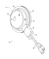
- FIG. 1 is a perspective view of a non-contact balance head and stator
- FIG. 3 is an exploded perspective view of the balance head and stator shown in FIG. 2
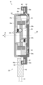
- FIG. 4 is a cross-sectional view of the balance head and stator shown in FIG. 2 taken along line 4-4
- FIG. 5 is an explanatory diagram for explaining the effect of the autobalancer of the present embodiment with respect to the autobalancer of the comparative example
- FIG. 1 is a schematic diagram showing an example in which the autobalancer 16 of the present invention is applied to a grinding device 10.
- the grinding device 10 is used, for example, for grinding a workpiece W, and includes a grinding wheel 12, a spindle 14, and an auto balancer 16.
- the grinding wheel 12 corresponds to the rotating body of the present invention and is shaped like a disc.
- the grinding wheel 12 is held by a spindle 14 so as to be rotatable about a rotating shaft 14a.
- a balance head 20 constituting an auto balancer 16 is connected to the grinding wheel 12 and rotates together with the balance head 20 .
- the spindle 14 incorporates a motor, and rotates the grinding wheel 12 at high speed around a rotating shaft 14a.
- the symbol Ax in the drawing indicates the axial direction of the rotating shaft 14a.
- the symbol ⁇ is the direction around the axis of rotation 14 a , that is, the direction of rotation of grinding wheel 12 and balance head 20 .
- the auto balancer 16 automatically corrects the imbalance of the grinding wheel 12 rotating at high speed.
- the autobalancer 16 includes a non-contact balance head 20 and stator 22 , a vibration sensor 24 and a controller 26 .
- the auto balancer 16 may be provided with a detection sensor for detecting the rotation angle of the balance head 20 (see Patent Document 2 above).
- the balance head 20 is connected to the grinding wheel 12 via an adapter flange 28. As a result, as described above, the grinding wheel 12 and the balance head 20 rotate integrally in the direction ⁇ around the axis.
- the balance head 20 operates based on drive power and drive commands that are non-contactly input from the controller 26 via the stator 22 to correct the unbalance of the grinding wheel 12 during high-speed rotation.
- FIG. 2 is a perspective view of the non-contact balance head 20 and stator 22.
- FIG. FIG. 3 is an exploded perspective view of balance head 20 and stator 22 shown in FIG.
- FIG. 4 is a cross-sectional view of balance head 20 and stator 22 shown in FIG. 2 along line 4--4.
- the balance head 20 includes a case 30, a rotor section 32, a balance correction mechanism 34, an AE sensor 36, and a control board 38.
- the case 30 is formed in a hollow columnar shape parallel to the axial direction Ax.
- the case 30 comprises a disc-shaped front end face 30a and a disc-shaped rear end face 30b which are spaced apart in the axial direction Ax and perpendicular to the axial direction Ax, and a cylindrical outer peripheral face 30c parallel to the axial direction Ax. It is
- the outer peripheral surface 30c connects the peripheral edge portion of the front end surface 30a and the peripheral edge portion of the rear end surface 30b.
- the outer peripheral surface 30c is configured to be divisible in two in the axial direction Ax.
- An electric balance correction mechanism 34 is housed in the space inside the case 30 .
- a control board 38 and an AE sensor 36 are provided in the wall portion forming the rear end face 30b.
- the balance correction mechanism 34 includes two balance weights 34a and two sets of motor drive mechanisms 34b. Each balance weight 34a is held by a different motor driving mechanism 34b so as to be displaceable in the direction ⁇ around the axis about the axial direction Ax. Each motor drive mechanism 34b is composed of, for example, a motor and a plurality of gears. Each motor drive mechanism 34b receives power supply from the control board 38 and displaces each balance weight 34a in the axial direction ⁇ independently of each other. Note that the balance correction mechanism 34 is not particularly limited to the one shown in the drawing, and various known types can be employed.
- the AE sensor 36 is an acoustic emission (AE) sensor and corresponds to the detection sensor of the present invention.
- the AE sensor 36 detects a high-frequency sound generated when the workpiece W, the dresser, or another contact object contacts the grinding wheel 12, and outputs a detection signal of this sound to the control board 38. .
- the rotor portion 32 is provided on the outer peripheral surface 30c and rotates integrally with the balance head 20 in the direction ⁇ around the axis.
- the rotor portion 32 is formed in a shape along the circumferential direction (direction ⁇ around the axis) of the outer peripheral surface 30c, more specifically, in a ring shape (flange shape).
- a rotor coil 32a which is a ring-shaped antenna coil, is provided in the rotor portion 32. As shown in FIG. Although the rotor portion 32 is formed integrally with the case 30 in this embodiment, the rotor portion 32 formed separately from the case 30 may be fixed to the case 30 .
- the rotor coil 32a is electrically connected to the control board 38, and further electrically connected to the balance correction mechanism 34 and the like through the control board 38.
- the rotor coil 32a receives driving power wirelessly transmitted (power transmission) from the stator 22, which will be described later, and a drive command for the balance correction mechanism 34 wirelessly transmitted (information transmission) from the stator 22 as well.
- the rotor coil 32 a wirelessly transmits (information transmits) the detection signal of the AE sensor 36 input from the control board 38 to the stator 22 .
- the control board 38 has a processor such as a CPU (Central Processing Unit), a power receiving circuit, a power transmission circuit, a reception demodulator, a transmission modulator, and the like, and controls the operation of each part of the balance head 20 and power supply to each part. Control. After converting the drive power (AC power) received by the rotor coil 32a into DC power, the control board 38 supplies this drive power to the balance correction mechanism 34, the AE sensor 36, and the like. The control board 38 also outputs the drive command received by the rotor coil 32 a to the balance correction mechanism 34 . Further, the control board 38 controls the energization of the rotor coil 32 a to wirelessly transmit the detection signal of the AE sensor 36 from the rotor coil 32 a to the stator 22 .
- a processor such as a CPU (Central Processing Unit), a power receiving circuit, a power transmission circuit, a reception demodulator, a transmission modulator, and the like, and controls the operation of each part of the balance head 20 and power supply
- the stator 22 is provided separately from the balance head 20.
- the stator 22 functions as a sender that wirelessly transmits the drive power and drive command for the balance head 20 that are output from the controller 26 to the rotor section 32 . It functions as a receiver that receives and outputs to the controller 26 .
- the stator 22 includes a stator ring 40 , a transmission/reception control section 42 and a signal cable 44 .
- the stator ring 40 is formed in a ring shape along the circumferential direction of the outer peripheral surface 30c. Specifically, the inner diameter of the stator ring 40 is formed to be larger than the outer diameter of the outer peripheral surface 30c, and is loosely fitted (with a gap) on the outer peripheral surface 30c. In other words, case 30 is inserted into the space surrounded by stator ring 40 .
- the stator ring 40 is attached to a fixing portion (for example, a machine guard) (not shown) of the grinding device 10 provided near the grinding wheel 12 so that the stator ring 40 faces the rotor portion 32 in the axial direction Ax. Also, it is fixed at a position close to the rotor portion 32 . This allows wireless transmission between the stator ring 40 and the rotor portion 32 .
- a stator coil 40a which is a ring-shaped antenna coil, is provided.
- the stator coil 40a performs wireless transmission of drive power, drive commands, detection signals, etc. with the rotor coil 32a under the control of the transmission/reception control unit 42, which will be described later.
- the transmission/reception control section 42 is composed of a transmission modulation section (transmitter), a reception demodulation section, and the like.
- the transmission/reception control unit 42 is electrically connected to the controller 26 via a signal cable 44, and is also electrically connected to the stator coil 40a.
- the transmission/reception control unit 42 controls the energization of the stator coil 40a based on the drive power input from the controller 26, thereby transferring the drive power to the rotor coil by a known method such as an electromagnetic dielectric method, a magnetic field resonance method, and an electric field resonance method. 32a.
- the transmission/reception control unit 42 controls energization of the stator coil 40a based on the drive command for the balance head 20 input from the controller 26, thereby wirelessly transmitting the drive command to the rotor unit 32 in a known manner. Thereby, the driving power and the driving command are transmitted from the stator 22 to the balance head 20 in a non-contact manner.
- the transmission/reception control unit 42 outputs to the controller 26 the detection signal of the AE sensor 36 that is transmitted from the rotor coil 32a to the stator coil 40a in a non-contact manner.
- the vibration sensor 24 is attached to the spindle 14. Also, the vibration sensor 24 is connected to the controller 26 via a signal cable 50 . The vibration sensor 24 detects low-frequency vibration that appears in the spindle 14 due to unbalance of the grinding wheel 12 rotated at high speed by the spindle 14 and outputs a vibration detection signal to the controller 26 .
- the controller 26 centrally controls the supply of drive power to the balance head 20, the drive of the balance head 20, and the vibration detection by the vibration sensor 24.
- the controller 26 outputs drive power for the balance head 20 to the transmission/reception control unit 42 while the spindle 14 is rotating the grinding wheel 12 . While the drive power is being input from the controller 26, the transmission/reception control unit 42 controls the energization of the stator coil 40a to wirelessly transmit the drive power from the stator coil 40a to the rotor coil 32a. The drive power received by the rotor coil 32 a is supplied to each part of the balance head 20 via the control board 38 . As a result, the balance head 20 and the AE sensor 36 are activated.
- the AE sensor 36 starts acoustic detection and continuously outputs acoustic detection signals to the control board 38 .
- the control board 38 controls the energization of the rotor coil 32a based on the sound detection signal. is wirelessly transmitted.
- the acoustic detection signal received by the stator coil 40 a is output to the controller 26 by the transmission/reception control section 42 . Thereby, the controller 26 can detect that the workpiece W or the like has come into contact with the grinding wheel 12 based on the sound detection signal.
- the controller 26 operates the vibration sensor 24 while the spindle 14 is rotating the grinding wheel 12 .
- vibration detection signals are continuously input from the vibration sensor 24 to the controller 26 .
- the controller 26 determines the placement of each balance weight 34a within the balance correction mechanism 34 capable of correcting the imbalance of the grinding wheel 12 by a known method.
- the controller 26 generates a drive command for driving the balance correction mechanism 34 and outputs this drive command to the transmission/reception control unit 42 each time the placement of each balance weight 34a is determined.
- the transmission/reception control unit 42 controls energization of the stator coil 40a to wirelessly transmit the drive command from the stator coil 40a to the rotor coil 32a.
- the drive command received by the rotor coil 32 a is input to the balance correction mechanism 34 via the control board 38 .
- the imbalance of the grinding wheel 12 during high-speed rotation is corrected by driving the balance correction mechanism 34 according to the drive command.
- FIG. 5 is an explanatory diagram for explaining the effect of the autobalancer 16 of this embodiment on the autobalancer 100 of the comparative example.
- the autobalancer 100 of the comparative example includes a balance head 102 and a stator 104, and a rotor 106 is provided on the front end surface of the balance head 102 via an adapter 102a. Furthermore, a stator 104 is arranged at a position facing this rotor 106 .
- the balance head 102, the adapter 102a, the rotor 106, and the stator 104 are arranged in series along the axial direction Ax, the length LA of the autobalancer 100 becomes long.
- the stator 22 is provided with a ring-shaped stator ring 40, and the stator ring 40 is loosely fitted on the outer peripheral surface 30c of the balance head 20, so that the rotor portion 32 is It can be formed on the outer peripheral surface 30c and further eliminates the need for the adapter 102a of the comparative example.
- the length LB in the axial direction Ax of the entire autobalancer 16 becomes equal to the length in the axial direction Ax of only the balance head 20, and the length in the axial direction Ax can be significantly shortened compared to the comparative example. .
- the installation space of the auto balancer 16 in the grinding apparatus 10 can be saved. Further, since the auto balancer 16 is installed in the grinding device 10, the case for housing the grinding wheel 12 does not need to be improved.
- the outer peripheral surface 30c of the case 30 is formed in a cylindrical shape. It may be formed in a cylindrical shape other than the above.
- the rotor portion 32 (rotor coil 32a) and the stator ring 40 (stator coil 40a) are each formed in a ring shape. If possible, it may be formed in a shape other than a ring shape such as a quadrangular ring (polygonal ring).
- the rotor portion 32 and the stator ring 40 are each formed in a ring shape. Instead, it may be formed, for example, in the shape of an arc or in the shape of a half ring. In order to always enable wireless transmission of driving power and the like between the rotor portion 32 and the stator ring 40, either one of the rotor portion 32 and the stator ring 40 may be formed in a ring shape. desirable.
- the rotor portion 32 is provided on the outer peripheral surface 30c and at a position facing the stator ring 40 in the axial direction Ax. , that is, the region surrounded by the stator ring 40 in the outer peripheral surface 30c.
- the auto balancer 16 that corrects the unbalance of the grinding wheel 12 of the grinding device 10 was described as an example.
- the present invention can also be applied to an autobalancer used for correction.
- the present invention can also be applied to correct imbalance of various rotating bodies in fields other than semiconductor manufacturing equipment.
Landscapes
- Physics & Mathematics (AREA)
- General Physics & Mathematics (AREA)
- Testing Of Balance (AREA)
- Manufacture Of Motors, Generators (AREA)
Abstract
Description
12 研削砥石
14 スピンドル
14a 回転軸
16 オートバランサ
20 バランスヘッド
22 ステータ
24 振動センサ
26 コントローラ
28 アダプターフランジ
30 ケース
30a 前端面
30b 後端面
30c 外周面
32 ロータ部
32a ロータコイル
34 バランス修正機構
34a バランスウェイト
34b モータ駆動機構
36 AEセンサ
38 制御基板
40 ステータリング
40a ステータコイル
42 送受信制御部
44,50 信号ケーブル
100 オートバランサ
102 バランスヘッド
102a アダプタ
104 ステータ
106 ロータ
Ax 軸方向
θ 軸周り方向
W 被加工物 10
Claims (6)
- 回転体の回転軸を中心として前記回転体と一体に回転するバランスヘッドであって、前記回転体のアンバランスを修正する電動型のバランス修正機構と、前記回転軸に平行な筒状の外周面を有し且つ前記バランス修正機構を収納するケースと、を有するバランスヘッドと、
前記バランスヘッドとは別体に設けられ、前記外周面に対して隙間をあけた状態で前記外周面の周方向に沿う形状を有するステータであって、前記バランスヘッドのコントローラに電気的に接続されたステータと、
前記外周面上において前記ステータに対向する位置に設けられ、前記バランスヘッドと一体に回転するロータ部であって、前記外周面の周方向に沿う形状を有し且つ前記バランス修正機構に電気的に接続されたロータ部と、
を備え、
前記ステータと前記ロータ部との間で無線伝送が可能であるオートバランサ。 A balance head that rotates integrally with the rotating body about the rotation axis of the rotating body, and includes an electric balance correction mechanism that corrects imbalance of the rotating body, and a cylindrical outer peripheral surface that is parallel to the rotating shaft. and a case housing the balance correction mechanism;
A stator that is provided separately from the balance head and has a shape along the circumferential direction of the outer peripheral surface with a gap from the outer peripheral surface, and is electrically connected to a controller of the balance head. a stator and
A rotor portion provided on the outer peripheral surface at a position facing the stator and rotating integrally with the balance head, having a shape along the circumferential direction of the outer peripheral surface and electrically connected to the balance correction mechanism. a connected rotor portion;
with
An autobalancer capable of wireless transmission between the stator and the rotor section. - 前記ステータが、前記外周面の周方向に沿ってリング状に形成されており、前記外周面に対して遊嵌されている請求項1に記載のオートバランサ。 The auto balancer according to claim 1, wherein the stator is formed in a ring shape along the circumferential direction of the outer peripheral surface and loosely fitted to the outer peripheral surface.
- 前記ロータ部が、前記外周面の周方向に沿ってリング状に形成されている請求項1または2に記載のオートバランサ。 The auto balancer according to claim 1 or 2, wherein the rotor portion is formed in a ring shape along the circumferential direction of the outer peripheral surface.
- 前記ステータ及び前記ロータ部が、前記回転軸の軸方向において互いに対向している請求項1から3のいずれか1項に記載のオートバランサ。 The auto balancer according to any one of claims 1 to 3, wherein the stator and the rotor section face each other in the axial direction of the rotating shaft.
- 前記ステータが、前記コントローラから出力された前記バランスヘッドの駆動電力及び駆動指令を前記ロータ部へ無線伝送し、
前記ロータ部が、前記ステータから前記駆動電力及び前記駆動指令を受信し、
前記バランス修正機構が、前記ロータ部が受信した前記駆動電力及び前記駆動指令に基づき作動する請求項1から4のいずれか1項に記載のオートバランサ。 the stator wirelessly transmits the drive power and the drive command for the balance head output from the controller to the rotor unit;
the rotor unit receives the drive power and the drive command from the stator;
The autobalancer according to any one of claims 1 to 4, wherein the balance correction mechanism operates based on the drive power and the drive command received by the rotor section. - 前記ケースに設けられ、前記回転体への被接触物の接触を検知する検知センサを備え、
前記ロータ部が、前記検知センサの検出信号を前記ステータへ無線伝送し、
前記ステータが、前記ロータ部から受信した前記検出信号を前記コントローラに入力する請求項1から5のいずれか1項に記載のオートバランサ。 A detection sensor that is provided in the case and detects contact of a contacting object with the rotating body,
The rotor section wirelessly transmits a detection signal of the detection sensor to the stator,
The autobalancer according to any one of claims 1 to 5, wherein the stator inputs the detection signal received from the rotor portion to the controller.
Priority Applications (3)
| Application Number | Priority Date | Filing Date | Title |
|---|---|---|---|
| KR1020247025378A KR20240123391A (en) | 2022-01-31 | 2022-12-12 | Auto balancer |
| CN202280090424.4A CN118633017A (en) | 2022-01-31 | 2022-12-12 | Automatic balancer |
| JP2023576679A JPWO2023145279A1 (en) | 2022-01-31 | 2022-12-12 |
Applications Claiming Priority (2)
| Application Number | Priority Date | Filing Date | Title |
|---|---|---|---|
| US202263304971P | 2022-01-31 | 2022-01-31 | |
| US63/304,971 | 2022-01-31 |
Publications (1)
| Publication Number | Publication Date |
|---|---|
| WO2023145279A1 true WO2023145279A1 (en) | 2023-08-03 |
Family
ID=87471567
Family Applications (1)
| Application Number | Title | Priority Date | Filing Date |
|---|---|---|---|
| PCT/JP2022/045623 WO2023145279A1 (en) | 2022-01-31 | 2022-12-12 | Auto balancer |
Country Status (5)
| Country | Link |
|---|---|
| JP (1) | JPWO2023145279A1 (en) |
| KR (1) | KR20240123391A (en) |
| CN (1) | CN118633017A (en) |
| TW (1) | TW202404740A (en) |
| WO (1) | WO2023145279A1 (en) |
Citations (10)
| Publication number | Priority date | Publication date | Assignee | Title |
|---|---|---|---|---|
| JPH0319766A (en) * | 1989-06-16 | 1991-01-28 | Hitachi Seiko Ltd | Dynamic balancer for rotary unit |
| WO1996017294A1 (en) * | 1994-11-29 | 1996-06-06 | Balance Dynamics Corporation | Electromagnetically actuated rotating machine unbalance compensator |
| JPH08508096A (en) * | 1993-03-22 | 1996-08-27 | マーポス、ソチエタ、ペル、アツィオーニ | Rotating body dynamic balancing device |
| JP2001232563A (en) | 2000-02-18 | 2001-08-28 | Okamoto Machine Tool Works Ltd | Grinding device, and balancing method for grinding wheel of grinding device |
| US20060005623A1 (en) * | 2004-07-12 | 2006-01-12 | Lord Corporation | Rotating machine active balancer and method of dynamically balancing a rotating machine shaft with torsional vibrations |
| JP2011095163A (en) | 2009-10-30 | 2011-05-12 | Tokyo Seimitsu Co Ltd | Auto balancer |
| JP2015200650A (en) * | 2014-04-09 | 2015-11-12 | バランス システムズ エス.アール.エル. | Dynamic balance process of rotor, and device |
| EP3869174A1 (en) * | 2020-02-20 | 2021-08-25 | Balance Systems S.r.L. | Balancing device for rotating parts |
| EP3869173A1 (en) * | 2020-02-20 | 2021-08-25 | Balance Systems S.r.L. | Balancing device for rotating parts |
| US20210379728A1 (en) * | 2020-06-03 | 2021-12-09 | Balance Systems S.R.L. | Balancing device for rotating pieces |
-
2022
- 2022-12-12 JP JP2023576679A patent/JPWO2023145279A1/ja active Pending
- 2022-12-12 KR KR1020247025378A patent/KR20240123391A/en active Search and Examination
- 2022-12-12 CN CN202280090424.4A patent/CN118633017A/en active Pending
- 2022-12-12 WO PCT/JP2022/045623 patent/WO2023145279A1/en active Application Filing
-
2023
- 2023-01-09 TW TW112100824A patent/TW202404740A/en unknown
Patent Citations (10)
| Publication number | Priority date | Publication date | Assignee | Title |
|---|---|---|---|---|
| JPH0319766A (en) * | 1989-06-16 | 1991-01-28 | Hitachi Seiko Ltd | Dynamic balancer for rotary unit |
| JPH08508096A (en) * | 1993-03-22 | 1996-08-27 | マーポス、ソチエタ、ペル、アツィオーニ | Rotating body dynamic balancing device |
| WO1996017294A1 (en) * | 1994-11-29 | 1996-06-06 | Balance Dynamics Corporation | Electromagnetically actuated rotating machine unbalance compensator |
| JP2001232563A (en) | 2000-02-18 | 2001-08-28 | Okamoto Machine Tool Works Ltd | Grinding device, and balancing method for grinding wheel of grinding device |
| US20060005623A1 (en) * | 2004-07-12 | 2006-01-12 | Lord Corporation | Rotating machine active balancer and method of dynamically balancing a rotating machine shaft with torsional vibrations |
| JP2011095163A (en) | 2009-10-30 | 2011-05-12 | Tokyo Seimitsu Co Ltd | Auto balancer |
| JP2015200650A (en) * | 2014-04-09 | 2015-11-12 | バランス システムズ エス.アール.エル. | Dynamic balance process of rotor, and device |
| EP3869174A1 (en) * | 2020-02-20 | 2021-08-25 | Balance Systems S.r.L. | Balancing device for rotating parts |
| EP3869173A1 (en) * | 2020-02-20 | 2021-08-25 | Balance Systems S.r.L. | Balancing device for rotating parts |
| US20210379728A1 (en) * | 2020-06-03 | 2021-12-09 | Balance Systems S.R.L. | Balancing device for rotating pieces |
Also Published As
| Publication number | Publication date |
|---|---|
| KR20240123391A (en) | 2024-08-13 |
| TW202404740A (en) | 2024-02-01 |
| CN118633017A (en) | 2024-09-10 |
| JPWO2023145279A1 (en) | 2023-08-03 |
Similar Documents
| Publication | Publication Date | Title |
|---|---|---|
| EP0690979B1 (en) | Apparatus for the dynamic balancing of a rotating body | |
| JP5551408B2 (en) | Rotation angle detector | |
| CN105501287B (en) | Driving device and electric power steering apparatus | |
| TWI689375B (en) | Device and method for transceiving alternating optical signals | |
| KR100809217B1 (en) | Detection signal transmitting apparatus | |
| JPWO2009001399A1 (en) | Motor rotation position detection device | |
| WO2023145279A1 (en) | Auto balancer | |
| JP2021189186A (en) | Balancing device for rotor | |
| JP2003097582A (en) | Bearing device with sensor | |
| JP6850304B2 (en) | Rotation position detector | |
| US20080317398A1 (en) | Magnetic bearing device and machine tool provided with the same | |
| JP2022526558A (en) | Machine tool rotary spindle balancing system and related control methods | |
| WO2007015486A1 (en) | Detection signal transmitter | |
| JP2011095163A (en) | Auto balancer | |
| KR102482384B1 (en) | Built-in motor ultrasonic vibration spindle apparatus | |
| CN211958894U (en) | Laser radar and rotary driving assembly thereof | |
| JP2011182569A (en) | Inner rotor type motor | |
| JP2011161520A (en) | Centerless grinding machine | |
| CN111987863A (en) | Motor control device, motor control method, and rotating electric machine | |
| EP3772390B1 (en) | Grinding machine tool with random eccentric orbital motion speed detection | |
| JP2007168051A (en) | Inner surface grinding machine | |
| US20240178728A1 (en) | Robot wheel driving apparatus | |
| US11839946B2 (en) | Grinding machine tool with random eccentric orbital motion speed detection | |
| JP2012055992A (en) | Power tool | |
| JP3128765B2 (en) | Brushless position confirmation device in rotating body |
Legal Events
| Date | Code | Title | Description |
|---|---|---|---|
| 121 | Ep: the epo has been informed by wipo that ep was designated in this application |
Ref document number: 22924130 Country of ref document: EP Kind code of ref document: A1 |
|
| ENP | Entry into the national phase |
Ref document number: 2023576679 Country of ref document: JP Kind code of ref document: A |
|
| ENP | Entry into the national phase |
Ref document number: 20247025378 Country of ref document: KR Kind code of ref document: A |
|
| ENP | Entry into the national phase |
Ref document number: 2022924130 Country of ref document: EP Effective date: 20240726 |
|
| WWE | Wipo information: entry into national phase |
Ref document number: 202447064921 Country of ref document: IN |