WO2023136355A1 - ギヤハウジングおよび電動アシスト装置 - Google Patents
ギヤハウジングおよび電動アシスト装置 Download PDFInfo
- Publication number
- WO2023136355A1 WO2023136355A1 PCT/JP2023/001063 JP2023001063W WO2023136355A1 WO 2023136355 A1 WO2023136355 A1 WO 2023136355A1 JP 2023001063 W JP2023001063 W JP 2023001063W WO 2023136355 A1 WO2023136355 A1 WO 2023136355A1
- Authority
- WO
- WIPO (PCT)
- Prior art keywords
- wheel
- housing
- worm
- straight line
- gear housing
- Prior art date
- Legal status (The legal status is an assumption and is not a legal conclusion. Google has not performed a legal analysis and makes no representation as to the accuracy of the status listed.)
- Ceased
Links
Images











Classifications
-
- B—PERFORMING OPERATIONS; TRANSPORTING
- B62—LAND VEHICLES FOR TRAVELLING OTHERWISE THAN ON RAILS
- B62D—MOTOR VEHICLES; TRAILERS
- B62D5/00—Power-assisted or power-driven steering
- B62D5/04—Power-assisted or power-driven steering electrical, e.g. using an electric servo-motor connected to, or forming part of, the steering gear
-
- F—MECHANICAL ENGINEERING; LIGHTING; HEATING; WEAPONS; BLASTING
- F16—ENGINEERING ELEMENTS AND UNITS; GENERAL MEASURES FOR PRODUCING AND MAINTAINING EFFECTIVE FUNCTIONING OF MACHINES OR INSTALLATIONS; THERMAL INSULATION IN GENERAL
- F16H—GEARING
- F16H1/00—Toothed gearings for conveying rotary motion
- F16H1/02—Toothed gearings for conveying rotary motion without gears having orbital motion
- F16H1/04—Toothed gearings for conveying rotary motion without gears having orbital motion involving only two intermeshing members
- F16H1/12—Toothed gearings for conveying rotary motion without gears having orbital motion involving only two intermeshing members with non-parallel axes
- F16H1/16—Toothed gearings for conveying rotary motion without gears having orbital motion involving only two intermeshing members with non-parallel axes comprising worm and worm-wheel
Definitions
- the present invention relates to an electric assist device and a gear housing that constitutes the electric assist device.
- Patent Document 1 International Publication No. 2019/087945
- the electric power steering device 100 includes an electric assist device 101.
- the electric assist device 101 has an output shaft 105 connected to the front end of the steering shaft 102 via a torsion bar 104, and applies assist driving force to the output shaft 105.
- the electric assist device 101 further includes a gear housing 106, a worm reduction gear 107, an electric motor 108, and a rear housing 109.
- the gear housing 106 is attached to the front end of the steering column 103 via a rear housing 109 .
- the gear housing 106 integrally includes a wheel housing portion 110 , a worm housing portion 111 and a hinge portion 112 .
- the wheel housing portion 110 is a portion that houses the worm wheel 113 of the worm reduction gear 107 inside.
- the wheel housing portion 110 includes a cylindrical wheel tube portion 114 arranged around the worm wheel 113 and an annular wheel bottom portion extending radially inward from the front end of the wheel tube portion 114 .
- the worm housing portion 111 is a portion that houses the worm 117 of the worm reduction gear 107 inside.
- the worm housing portion 111 has a bottomed tubular shape with one end in the axial direction (the upper side in FIG. 21) being open and the end on the other side in the axial direction (the lower side in FIG. 21) being closed. is configured to
- the worm housing portion 111 is connected to a portion of the radially outer end portion of the wheel housing portion 110 in the circumferential direction.
- the central axis of the worm housing portion 111 is arranged at a twisted position with respect to the central axis of the wheel housing portion 110 .
- the internal space of the worm housing portion 111 communicates with the internal space of the wheel housing portion 110 .
- the hinge portion 112 is connected to a portion of the wheel housing portion 110 that is separated from the worm housing portion 111 in the circumferential direction, and protrudes forward from the portion.
- the hinge portion 112 has an insertion hole 119 through which a tilt shaft 120 extending in the left-right direction and attached to the vehicle body is inserted.
- the electric assist device 101, the steering column 103, and the steering shaft 102 are supported so as to be able to swing around the tilt shaft 120 with respect to the vehicle body. This rocking motion enables adjustment of the vertical position of the steering wheel.
- the gear housing 106 further includes reinforcing ribs 121 a and 121 b spanning between the wheel housing portion 110 and the worm housing portion 111 .
- the worm 117 has worm teeth 122 on the outer peripheral surface of the axially intermediate portion.
- the worm 117 is rotatably supported inside the worm housing portion 111 by ball bearings 123a and 123b.
- the worm wheel 113 has wheel teeth 124 that mesh with the worm teeth 122 on its outer peripheral surface.
- the worm wheel 113 is externally fitted and fixed to the axial intermediate portion of the output shaft 105 .
- the output shaft 105 is rotatably supported inside the gear housing 106 and the rear housing 109 by ball bearings 125a and 125b.
- the electric motor 108 is fixed to one end of the worm housing portion 111 on the other side in the axial direction.
- a motor output shaft 118 of the electric motor 108 is connected to the base end of the worm 117 so as to transmit torque.
- the electric motor 108 applies assist driving force to the output shaft 105 via the worm speed reducer 107 .
- the gear housing 106 receives a force in the direction of separating the worm housing portion 111 and the wheel housing portion 110 from each other and a force in the direction of twisting each other.
- the gear housing 106 is subjected to such a complicated form of force, particularly in the wheel housing portion 110, a portion near the worm housing portion 111 is required to have a higher strength (rigidity) than other portions.
- the strength required for the wheel housing portion 110 varies depending on the location.
- the thickness of the wheel bottom portion 115 (excluding the reinforcing ribs 121a and 121b) that constitutes the wheel housing portion 110 is uniform throughout. There is room for
- An object of the present invention is to provide a gear housing that can easily achieve weight reduction while ensuring necessary strength, and an electric power assist device that includes the gear housing.
- a gear housing includes a wheel accommodating portion that accommodates a worm wheel inside, and a worm accommodating portion that accommodates a worm inside.
- the wheel housing portion includes a wheel tubular portion disposed around the worm wheel, and an annular wheel bottom portion extending radially inward from one axial end of the wheel tubular portion.
- the worm housing portion is formed in a tubular shape with an open end on one axial side to which the electric motor is fixed, and is arranged such that its central axis is twisted with respect to the central axis of the wheel housing portion. and is connected to a portion of the radially outer end of the wheel accommodating portion in the circumferential direction.
- a first imaginary straight line starting from the center portion of the wheel housing portion and perpendicular to the central axis of the worm housing portion and the center portion of the wheel housing portion are: Considering a reference imaginary straight line that passes through and has an opening angle of 75° or less including 0° with respect to the first imaginary straight line (within the range of 0° to 75°), the wheel The thickness of at least a portion of the bottom portion decreases from the side closer to the worm accommodating portion toward the farther side with respect to the direction of the virtual reference straight line.
- the opening angle between the first imaginary straight line and the reference imaginary straight line is preferably 60° or less, more preferably 30° or less, and even more preferably 15° or less.
- a gear housing includes a hinge portion having an insertion hole for inserting a tilt shaft.
- the hinge portion is connected to a portion of the wheel housing portion in the circumferential direction, and protrudes from the portion of the circumferential direction toward the front side in the axial direction of the wheel housing portion.
- the center portion of the wheel housing portion when viewed from one side in the axial direction of the wheel housing portion, the center portion of the wheel housing portion is a starting point, and the second gear is orthogonal to the center axis of the insertion hole of the hinge portion.
- the opening angle between the first virtual straight line and the second virtual straight line is 135 degrees or less including 0 degrees (within the range of 0 degrees to 135 degrees).
- the opening angle between the first virtual straight line and the second virtual straight line is preferably 90 degrees or less, more preferably 60 degrees or less, and even more preferably 30 degrees or less.
- the reference virtual straight line is a circumferential range sandwiched between the first virtual straight line and the second virtual straight line (on the first virtual straight line and/or on the (including on the second imaginary straight line).
- the side surface on one side in the axial direction or the side surface on the other side in the axial direction of the at least one portion of the wheel bottom portion is far from the side closer to the worm housing portion with respect to the direction of the reference imaginary straight line. It is composed of a flat surface or a curved surface inclined in a direction in which the thickness of the at least one portion decreases toward the side.
- At least a portion of a first connection portion that is a connection portion of the worm housing portion to the wheel housing portion, and a second connection portion that is a connection portion of the hinge portion to the wheel housing portion. are arranged at the same position with respect to the circumferential direction of the wheel housing portion, and when viewed from one side of the wheel housing portion in the axial direction, the reference imaginary straight line is aligned with the first connecting portion and the first 2 junctions.
- the wall thickness of the wheel tubular portion at the end farther from the worm accommodating portion with respect to the direction of the reference imaginary straight line is reduced in the axial direction. It becomes smaller as it goes to the axial direction other side from the side.
- An electric power assist device includes a worm wheel having wheel teeth on its outer peripheral surface, a worm having worm teeth on its outer peripheral surface that mesh with the wheel teeth, and a gear housing the worm wheel and the worm inside. and an electric motor that is supported by the gear housing and rotationally drives the worm, and the gear housing is configured by the gear housing according to one aspect of the present invention.
- FIG. 1 is a partially cutaway side view of an electric power steering apparatus according to a first embodiment of the present invention.
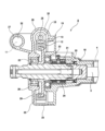
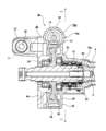
- FIG. 2 is a cross-sectional view of part A in FIG.
- FIG. 3 is a cross-sectional view along BB in FIG.
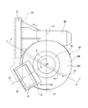
- FIG. 4 is a diagram of the gear housing of the first example viewed from the front side in the axial direction.
- FIG. 5 is a cross-sectional view taken along the line CC of FIG. 4, partly omitted.
- FIG. 6 is a cross-sectional view taken along line DD of FIG. 4, partly omitted.
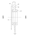
- FIG. 7 is a schematic diagram showing the wheel bottom portion and the wheel fitting tubular portion extracted from FIG. 5 .
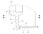
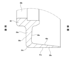
- FIG. 8 is a schematic diagram showing the lower end of FIG. 5 extracted.
- FIG. 9 is a schematic diagram for explaining a mold for molding the portion shown in FIG.
- FIG. 10 is a diagram corresponding to FIG. 8 regarding the second example of the embodiment of the present invention.
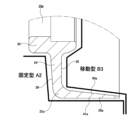
- FIG. 11 is a diagram corresponding to FIG. 9 regarding the second example.
- FIG. 12 is a diagram corresponding to FIG. 8 regarding the third example of the embodiment of the present invention.
- FIG. 13 is a diagram corresponding to FIG. 8 regarding the fourth example of the embodiment of the present invention.
- FIG. 14 is a diagram corresponding to FIG. 8 regarding a fifth example of the embodiment of the present invention.
- FIG. 15 is a diagram corresponding to FIG. 8 regarding the sixth example of the embodiment of the present invention.
- FIG. 16 is a diagram corresponding to FIG. 4, showing a seventh example of the embodiment of the present invention.
- FIG. 17 is a cross-sectional view taken along line EE of FIG.
- FIG. 18 is a diagram corresponding to FIG. 2, showing an eighth embodiment of the present invention.
- FIG. 19 is a cross-sectional view taken along the line FF of FIG. 18, partly omitted.
- FIG. 20 is a cross-sectional view showing an example of a conventional structure of an electric power steering device.
- 21 is a cross-sectional view taken along line GG of FIG. 20.
- FIG. FIG. 22 is a perspective view of a gear housing constituting one example of conventional structure.
- FIG. 1 A first example of an embodiment of the present invention will be described with reference to FIGS. 1 to 9.
- FIG. 1 A first example of an embodiment of the present invention will be described with reference to FIGS. 1 to 9.
- the electric power steering apparatus 1 of this example includes a steering wheel 2, a steering shaft 3, a steering column 4, a pair of universal joints 5a and 5b, an intermediate shaft 6, and a steering gear unit. 7 and an electric assist device 8 .
- the front-rear direction means the front-rear direction of the vehicle
- the left-right direction means the width direction of the vehicle
- the up-down direction means the up-down direction of the vehicle.
- the steering wheel 2 is supported and fixed to the rear end of the steering shaft 3 .
- the steering shaft 3 is rotatably supported inside a steering column 4 supported by the vehicle body.
- the front end of the steering shaft 3 is connected to a pinion shaft 9 of a steering gear unit 7 via a rear universal joint 5a, an intermediate shaft 6, and a front universal joint 5b. Therefore, when the driver rotates the steering wheel 2 , the rotation of the steering wheel 2 is transmitted to the pinion shaft 9 via the steering shaft 3 , the pair of universal joints 5 a and 5 b and the intermediate shaft 6 .
- the rotation of the pinion shaft 9 is converted into linear motion of a rack shaft (not shown) of the steering gear unit 7 meshed with the pinion shaft 9 .
- the pair of tie rods 10 is pushed and pulled, so that the left and right steered wheels are given a rudder angle corresponding to the amount of rotational operation of the steering wheel 2 .
- the electric power steering device 1 of this example includes a tilt mechanism for adjusting the vertical position of the steering wheel 2 according to the physique and driving posture of the driver. For this reason, the electric assist device 8 fixed to the front end portion of the steering column 4 is supported by the vehicle body so as to be swingable about a tilt shaft 11 extending in the left-right direction. The vertical position of the steering wheel 2 is adjusted by vertically swinging the steering shaft 3, the steering column 4, and the electric assist device 8 about the tilt shaft 11. As shown in FIG.
- the electric assist device 8 includes a worm wheel 12 having wheel teeth 13 on its outer peripheral surface, a worm 14 having worm teeth 15 meshing with the wheel teeth 13 on its outer peripheral surface, and a worm wheel 12. , and an electric motor 17 supported by the gear housing 16 and driving the worm 14 to rotate.
- the worm wheel 12 and the worm 14 are combined to form a worm speed reducer.
- the electric assist device 8 of this example further includes a sensor housing 18 fixed to the front end of the steering column 4, as shown in FIG.
- a housing 19 is configured by combining a gear housing 16 arranged on the front side and a sensor housing 18 arranged on the rear side.
- the electric assist device 8 of this example further includes a torsion bar 20 and an output shaft 21.
- the front end of the steering shaft 3 is inserted inside the housing 19 and connected to the output shaft 21 via the torsion bar 20 .
- a front end portion of the output shaft 21 protrudes forward from the inside of the housing 19 and is connected to the intermediate shaft 6 via a rear universal joint 5a (see FIG. 1).
- the output shaft 21 is rotatably supported on the housing 19 by ball bearings 22 and 23 at two axially separated locations.
- the electric assist device 8 of this example further includes a torque sensor 24 housed inside the sensor housing 18 and arranged around the output shaft 21 .
- Torque sensor 24 detects the direction and magnitude of torque applied from steering wheel 2 to steering shaft 3 .
- the electric motor 17 rotates the worm 14 based on the detection signal of the torque sensor 24 and the vehicle speed signal output from the vehicle speed sensor incorporated in the transmission, thereby assisting the output shaft 21 through the worm wheel 12. Provides driving force. As a result, the force required for the driver to rotate the steering wheel 2 is reduced.
- the gear housing 16, worm 14, worm wheel 12, and electric motor 17 are further described below.
- the gear housing 16 includes a wheel housing portion 25, a worm housing portion 26, and a hinge portion 27, as shown in FIGS.
- the gear housing 16 is integrally made of a light alloy such as an aluminum alloy or a thermoplastic resin. That is, in the following description, the connection between the respective parts constituting the gear housing 16 of this example means an integral connection.
- the gear housing 16 can be made, for example, by die-casting a light alloy such as an aluminum alloy, or by injection-molding a thermoplastic resin.
- the wheel housing portion 25 is a portion that houses the worm wheel 12 inside.
- the axial front side (left side in FIGS. 2 and 5) corresponds to one axial side
- the axial rear side (right side in FIGS. 2 and 5) corresponds to the other axial side. equivalent to the side.
- the wheel housing portion 25 includes a cylindrical wheel tube portion 28 arranged around the worm wheel 12 and extending radially inward from the axially front end of the wheel tube portion 28 . It has an annular wheel bottom portion 29 and a substantially cylindrical wheel fitting tube portion 30 connected to the radially inner end portion of the wheel bottom portion 29 .
- the radially inner end portion of the wheel bottom portion 29 is connected to the axially intermediate portion of the wheel fitting tubular portion 30 .
- the gear housing 16 and the sensor housing 18 are combined to form the housing 19, and the front end of the sensor housing 18 is fitted into the rear end of the wheel tubular portion 28, and , the front end face of the sensor housing 18 contacts the rear end face of the wheel cylinder portion 28 .
- the worm housing portion 26 is a portion that houses the worm 14 inside.
- the worm housing portion 26 has an open end on one axial side (left side in FIGS. 3 and 4) and a closed end on the other axial side (right side in FIGS. 3 and 4). It is configured in a loose, bottomed cylindrical shape.
- the worm housing portion is configured in a cylindrical shape with one end in the axial direction and the other end in the axial direction open, and the other end in the axial direction is open. can also be closed with a lid.
- the worm housing portion 26 is connected to a portion of the radially outer end portion of the wheel housing portion 25 in the circumferential direction.
- the worm housing portion 26 is connected to the upper end portion of the wheel housing portion 25 .
- the central axis of the worm housing portion 26 is arranged at a twisted position with respect to the central axis of the wheel housing portion 25 .
- the central axis of the worm housing portion 26 is arranged in the left-right direction.
- the internal space of the worm housing portion 26 communicates with the internal space of the wheel housing portion 25 .
- the worm housing portion 26 has a motor mounting flange 31 extending radially outward at one end in the axial direction.
- the motor mounting flange 31 is a portion for mounting the electric motor 17 and has a function of increasing the rigidity of the peripheral portion of the electric motor 17 in the gear housing 16 .
- the hinge portion 27 has an insertion hole 32 for inserting the tilt shaft 11 (see FIG. 1).
- the hinge portion 27 is connected to a portion of the wheel housing portion 25 in the circumferential direction, and protrudes from the portion of the circumferential direction toward the front side of the wheel housing portion 25 in the axial direction.
- the worm housing portion 26 and the hinge portion 27 of the wheel bottom portion 29 of the wheel housing portion 25 are It is preferable to employ a configuration in which the thickness of the portion near the worm housing portion 26 and the portion far from the hinge portion 27 is made thicker and the thickness of the portion farther from the worm housing portion 26 and the hinge portion 27 is made smaller, from the viewpoint of reducing weight while ensuring necessary strength. . Further, when adopting such a configuration, it is preferable that the positions of the worm housing portion 26 and the hinge portion 27 are not greatly separated from each other in the circumferential direction of the wheel housing portion 25 . Specifically, as shown in FIG.
- the center O of the wheel housing portion 25 is the starting point when viewed from the front side in the axial direction of the wheel housing portion 25
- the first center axis of the worm housing portion 26 is perpendicular to the central axis of the worm housing portion 26 .
- the first virtual straight line L1 and the second virtual straight line L2 it is preferable that the opening angle with the imaginary straight line L2 is 135° or less including 0° (within the range of 0° to 135°).
- the opening angle is preferably 90° or less, more preferably 60° or less, and even more preferably 30° or less.
- the opening angle is 0°
- the first imaginary straight line L1 and the second imaginary straight line L2 overlap each other.
- the hinge portion 27 is connected to the upper end portion of the wheel bottom portion 29 and the front side portion of the axially intermediate portion of the worm housing portion 26, and the axis of the wheel housing portion 25 extends from these portions. It protrudes toward the front side.
- the center axis of the insertion hole 32 of the hinge portion 27 is arranged in the left-right direction.
- the opening angle between the center portion O of the wheel housing portion 25 and the first imaginary straight line L1 is 0.
- the reference imaginary straight line Lb which is 75° or less (within the range of 0° to 75°) including °
- the thickness of at least a part of the wheel bottom part 29 is It becomes smaller from the side closer to the worm housing portion 26 toward the side farther from it. This point will be specifically described below.
- the opening angle between the first imaginary straight line L1 and the reference imaginary straight line Lb is preferably 60° or less, more preferably 30° or less, and even more preferably 15° or less. In this example, the opening angle is 0°. That is, the reference imaginary straight line Lb overlaps the first imaginary straight line L1 and the second imaginary straight line L2, and extends vertically. In this example, as shown in FIG.
- the reference imaginary straight line Lb passes through both the first connection portion J1 and the second connection portion J2.
- the overall thickness of the wheel bottom portion 29 increases in the direction indicated by the arrow S1 in FIGS. It gets smaller as you go.
- the overall thickness of the wheel bottom portion 29 decreases in the direction away from the central axis of the worm housing portion 26.
- the thickness decreases from the upper side to the lower side in FIGS. 4, 5 and 7 . 4, 5, and 7 are the upper side and the lower side in the vertical direction of the vehicle. For this reason, in this example, as shown in an exaggerated manner in FIG.
- the front side surface 39 of the wheel bottom portion 29 is formed of a flat surface, and the front side surface 39 of the wheel bottom portion 29 is formed of a plane inclined in a direction in which the thickness of the wheel bottom portion 29 decreases toward the direction indicated by the arrow S1, that is, in a rearward direction. are doing.
- the thickness of the wheel bottom portion 29 does not change in the direction perpendicular to both the center axis of the wheel housing portion 25 and the reference imaginary straight line Lb (horizontal direction in FIGS. 4 and 6).
- the thickness t1 of the upper end portion, which is the thickest portion of the wheel bottom portion 29, and the lower end portion, which is the thinnest portion of the wheel bottom portion 29, The difference from the thickness t2 can be set arbitrarily.
- the thickness t2 is preferably 90% or less of the thickness t1, more preferably 80% or less of the thickness t1.
- the thickness of the thinnest portion of the gear housing 16 is 0.8 mm or more, and 1 mm or more. It is more preferable to ensure
- the thickness of the wheel tubular portion 28 does not change in the axial direction.
- the thickness of the wheel tube portion 28 can be decreased or increased from the rear side toward the front side.
- the thickness of the wheel tube portion 28 decreases from the front side to the rear side.
- the inner peripheral surface 40 of the wheel cylinder portion 28 is configured by a cylindrical surface whose diameter does not change in the axial direction, and the wheel cylinder portion
- An outer peripheral surface 41 of 28 is formed of a tapered cylindrical surface whose diameter decreases from the front side to the rear side.
- the portion where the wall thickness of the wheel tubular portion decreases from the front side to the rear side may be only the lower end portion of the wheel tubular portion.
- the lower end of the wheel cylinder is, for example, a position where the height from the lower edge of the wheel cylinder is about 10% to 30% of the outer diameter of the wheel cylinder. can also be an underlying portion.
- the thickness t4 is preferably 80% or less of the thickness t3.
- the thickness t4 corresponds to the thickness of the thinnest portion of the gear housing 16, it is preferable to ensure the thickness t4 to be 0.8 mm or more.
- the thickness t2 and the wall thickness t3 are appropriately defined.
- the wall thickness of the wheel tubular portion 28 may be constant in the axial direction, or may be increased from the front side to the rear side. can also In this example, the thickness t3 is made smaller than the thickness t2 (t3 ⁇ t2).
- the gear housing may be provided with protrusions such as ribs and bosses that protrude from the axial side surface of the wheel bottom portion, ribs that protrude from the peripheral surface of the wheel cylinder portion, A configuration with protrusions such as flanges can also be employed.
- these projections are parts separate from the wheel bottom part and the wheel tube part. That is, the height dimension of these protrusions is a dimension that is irrelevant to the thickness of the wheel bottom portion and the wheel tube portion.
- the cylindrical wheel fitting tube portion 30 is connected to the radial inner end portion of the wheel bottom portion 29 , but the wheel fitting tube portion 30 is also separate from the wheel bottom portion 29 . is the part of That is, the axial dimension of the wheel fitting tubular portion 30 is a dimension that is irrelevant to the thickness of the wheel bottom portion.
- the worm 14 has, as shown in FIG. , with female splines 33 .
- the worm 14 is rotatably supported inside the worm housing portion 26 by ball bearings 34 and 35 .
- the worm wheel 12 has wheel teeth 13 on its outer peripheral surface, and is rotatably supported inside the wheel housing portion 25 .
- the worm wheel 12 is externally fitted and fixed to a portion of the output shaft 21 located between the two ball bearings 22 and 23 .
- a ball bearing 22, which is a wheel bearing, is fitted inside a wheel fitting tubular portion 30 of the wheel housing portion 25, and is fitted outside a portion of the output shaft 21 adjacent to the front side of the worm wheel 12.
- the ball bearing 23 is fitted internally to the front end of the sensor housing 18 and externally fitted to a portion of the output shaft 21 adjacent to the rear side of the worm wheel 12 .
- the electric motor 17 is fixed to the motor mounting flange 31 of the worm housing 26, as shown in FIG.
- the electric motor 17 has a male spline 37 on the outer peripheral surface of the tip portion of the motor output shaft 36 .
- the motor output shaft 36 and the worm 14 are connected so that torque can be transmitted.
- the method of connecting the motor output shaft and the worm so that torque can be transmitted is not particularly limited. It is also possible to connect so that torque can be transmitted via such a coupling.
- the gate of the mold which serves as a supply port for the molten material, is placed in the worm housing portion of the cavity for molding the gear housing 16. It is arranged at one or a plurality of locations in the upper end portion (the portion corresponding to the portion X1 in FIG. 4) of the worm housing portion molding space for molding the worm 26 . That is, the gate is arranged so that the worm housing portion molding space is on the upstream side. As a result, the material that has passed through the worm housing portion molding space is transferred to the hinge portion molding space for molding the hinge portion 27 of the cavity and the wheel housing portion molding space for molding the wheel housing portion 25 of the cavity. It is made to flow to the side.
- the gear housing 16 when the gear housing 16 is manufactured by die casting or injection molding, as shown in FIG. A stationary mold A1 for molding the side surface 39, a movable mold B1 for molding the rear side surface 38 of the wheel bottom portion 29 and the inner peripheral surface 40 of the wheel tubular portion 28, and a moving mold for molding the outer peripheral surface 41 of the wheel tubular portion 28.
- Type B2 is used.
- the movable molds B1 and B2 are capable of moving farther and nearer in the axial direction (horizontal direction in FIG. 9) with respect to the fixed mold A1.
- the gear housing 16 when the gear housing 16 is removed from the cavity after the material poured into the cavity has solidified, the inclination of the outer peripheral surface 41 of the wheel cylinder portion 28 is used as a draft angle with respect to the movable die B2.
- a meshing reaction force is applied to the worm 14 and the worm wheel 12 from the meshing portion between the worm tooth 15 and the wheel tooth 13 . Furthermore, these meshing reaction forces are transmitted from the worm 14 to the worm housing portion 26 via the ball bearings 34 and 35 and from the worm wheel 12 to the wheel housing portion 25 via the ball bearings 22 . As a result, as shown in FIG. 4, the gear housing 16 is subjected to a force F1 in the direction of separating the worm housing portion 26 and the wheel housing portion 25 and a force F2 in the direction of twisting each other.
- the worm teeth 15 and the wheel teeth 13 have a lead angle. Also, the directions of the forces F2 in the twisting directions are reversed according to the rotation direction of the worm 14 .
- the wheel housing portion 25 constituting the gear housing 16 since the gear housing 16 is subjected to the forces F1 and F2 in such a complicated manner, the wheel housing portion 25 constituting the gear housing 16 in particular bears the force F2 in the torsional direction at a portion near the worm housing portion 26 and at the wheel housing portion 25 that constitutes the gear housing 16. Higher strength (rigidity) is required at a location near the hinge portion 27 than at other locations. Therefore, in this example, it is desirable that the thickness of the upper half of the wheel accommodating portion 25 be increased in order to secure strength (rigidity) against the forces F1 and F2. On the other hand, since the lower half of the wheel accommodating portion 25 is not much affected by the forces F1 and F2, it is desirable to reduce its thickness from the viewpoint of weight reduction.
- the thickness of the entire wheel bottom portion 29 varies from the side closer to the worm housing portion 26 to the farther side in the direction of the reference imaginary straight line Lb. It gets smaller as you go. More specifically, in this example, the opening angle is 0°, and the reference imaginary straight line Lb extends vertically through both the first connection portion J1 and the second connection portion J2. there is As a result, the overall thickness of the wheel bottom portion 29 decreases from the top to the bottom. That is, the thickness of the upper half portion of the wheel housing portion 25 is large, and the thickness of the lower half portion of the wheel housing portion 25 is small. Therefore, it is easy to ensure the strength of the upper half of the wheel housing portion 25 and reduce the weight of the gear housing 16 . That is, in this example, the weight of the gear housing 16 can be easily reduced while ensuring the required strength.
- the thickness of the wheel tubular portion 28 decreases from the front side to the rear side. Therefore, also from this point, it is possible to contribute to the weight reduction of the gear housing 16 .
- gear housing 16 that constitutes the electric assist device 8 of this example it is easy to ensure moldability during manufacturing.
- the thickness of the entire wheel bottom portion 29 that constitutes the gear housing 16 is It becomes smaller from the side closer to the worm housing portion 26 toward the side farther from it. Therefore, when the gear housing 16 is manufactured by die-cast molding or injection molding, the material that has flowed from the worm housing molding space to the wheel housing molding space is spread in the wheel housing molding space with respect to the direction of the reference imaginary straight line Lb. The worm can be efficiently flowed from the side closer to the molding space of the worm housing portion toward the far side. Therefore, from this, it is easy to ensure moldability when manufacturing the gear housing 16 .
- the front side surface 39 of the wheel bottom portion 29 is formed of a flat surface that is inclined rearward in the direction indicated by the arrow S1, that is, a tapered surface.
- the material that has flowed from the worm housing portion molding space to the wheel housing portion molding space is transferred to the front side surface of the wheel bottom portion 29 .
- 39 can be made to flow smoothly. Accordingly, this also makes it easier to ensure moldability during manufacturing of the gear housing 16 .
- the thickness of the wheel tubular portion 28 decreases from the front side to the rear side. Therefore, when the gear housing 16 is manufactured by die casting or injection molding, the wheel cylinder portion 28 is molded from the space for molding the wheel bottom portion 29 in the space for molding the lower half portion of the wheel cylinder portion 28 .
- the material that has flowed into the space can be efficiently flowed from the front side to the rear side. Accordingly, this also makes it easier to ensure moldability during manufacturing of the gear housing 16 .
- FIG. 10 A second example of the embodiment of the invention will be described with reference to FIGS. 10 and 11.
- FIG. 10 A second example of the embodiment of the invention will be described with reference to FIGS. 10 and 11.
- the thickness of the wheel tubular portion 28a in the lower half portion of the wheel accommodating portion 25a constituting the gear housing 16a increases from the front side to the rear side. It gets smaller as you go.
- the outer peripheral surface 41a of the wheel tube portion 28a is configured by a cylindrical surface whose diameter does not change in the axial direction, and the wheel tube portion 28a is configured with a cylindrical surface whose diameter does not change in the axial direction.
- the inner peripheral surface 40a of is composed of a tapered cylindrical surface whose diameter increases from the front side to the rear side.
- the gear housing 16a is manufactured by die casting or injection molding
- a mold for molding the lower half of the wheel housing portion 25a as shown in FIG.
- a fixed die A2 for forming the side surface 39 and the outer peripheral surface 41a of the wheel tubular portion 28a and a movable die B3 for forming the rear side surface 38 of the wheel bottom portion 29 and the inner peripheral surface 40a of the wheel tubular portion 28a are used as a mold for molding the lower half of the wheel housing portion 25a, as shown in FIG.
- a fixed die A2 for forming the side surface 39 and the outer peripheral surface 41a of the wheel tubular portion 28a and a movable die B3 for forming the rear side surface 38 of the wheel bottom portion 29 and the inner peripheral surface 40a of the wheel tubular portion 28a are used.
- the movable mold B3 is capable of moving farther and nearer in the axial direction (horizontal direction in FIG. 11) with respect to the fixed mold A2.
- the overall thickness of the wheel bottom portion 29a of the wheel housing portion 25b that constitutes the gear housing 16b decreases from the top to the bottom.
- the front side surface 39a of the wheel bottom portion 29a is configured by a plane orthogonal to the central axis of the wheel housing portion 25a, and the rear surface of the wheel bottom portion 29a is
- the side surface 38a is formed of a flat surface that is inclined forward from the upper side to the lower side.
- the wheel cylindrical portion 28a has the same structure as in the second example, and the wheel bottom portion 29a has the same structure as in the third example.
- Other configurations and effects are the same as those of the second example.
- the front side surface 39b of the wheel bottom portion 29b of the wheel housing portion 25d that constitutes the gear housing 16d is formed of a concave curved surface that is inclined rearward from the upper side toward the lower side.
- Other configurations and effects are the same as those of the second example.
- the front side surface 39c of the wheel bottom portion 29c of the wheel housing portion 25e that constitutes the gear housing 16e has an inclined surface portion 42 that is inclined rearward from the upper side toward the lower side. have.
- a portion above the inclined surface portion 42 and a portion below the inclined surface portion 42 are formed of planes perpendicular to the central axis of the wheel accommodating portion 25e.
- Other configurations and effects are the same as those of the second example.
- the inclined surface portion is provided only on a part of the side surface of the wheel bottom portion as in the sixth example, the position and range of the inclined surface portion with respect to the direction of the reference imaginary straight line can be set arbitrarily. can be done.
- FIG. 16 A seventh example of the embodiment of the present invention will be described with reference to FIGS. 16 and 17.
- FIG. 16 A seventh example of the embodiment of the present invention will be described with reference to FIGS. 16 and 17.
- the starting point is the center O of the wheel housing portion 25f and is perpendicular to the central axis of the worm housing portion 26.
- a second imaginary straight line L2 starting from the center O of the wheel accommodating portion 25f and perpendicular to the central axis of the insertion hole 32 of the hinge portion 27, the first imaginary straight line
- the opening angle ⁇ between L1 and the second imaginary straight line L2 is about 120°.
- a first connection portion J1 that is a connection portion of the worm housing portion 26 to the wheel housing portion 25f of the gear housing 16f, and a second connection portion J2 that is a connection portion of the hinge portion 27 to the wheel housing portion 25f. are arranged at different positions in the circumferential direction of the wheel accommodating portion 25f.
- the hinge portion 27 interposes a third imaginary straight line L3 that passes through the center O of the wheel accommodating portion 25f and overlaps the first imaginary straight line L1 when viewed from the front side in the axial direction of the wheel accommodating portion 25f.
- the worm housing portion 26 is arranged in the area a1 where one axial end portion of the worm housing portion 26 exists.
- the reference imaginary straight line can also be a straight line that is inclined within a range of about ⁇ 15° with respect to the reference imaginary straight line Lb of this example.
- the overall thickness of the wheel bottom portion 29d is directed in the direction indicated by the arrow S1 in FIGS. becomes smaller according to Also in this example, the thickness of the wheel tube portion 28b changes in the axial direction in the half of the wheel tube portion 28b that is closer to the worm housing portion 26 with respect to the direction of the reference imaginary straight line Lb. not On the other hand, in the half portion of the wheel tube portion 28b that is farther from the worm housing portion 26 with respect to the direction of the reference imaginary straight line Lb, the wall thickness of the wheel tube portion 28b decreases from the front side toward the rear side. It's becoming
- the gate of the mold which serves as a supply port for the molten material, is placed in the worm housing portion of the cavity for molding the gear housing 16f.
- one end of worm accommodating portion 26 and hinge portion 27 are arranged at one or more locations in the space portion (portion corresponding to X2 in FIG. 16) to be molded.
- Other configurations and effects are the same as those of the first example.
- a gear housing 16g is integrally connected to the front end of a substantially cylindrical sensor housing 18a fixed to the front end of the steering column 4.
- the sensor housing 18a and the gear housing 16g are made of a light alloy such as an aluminum alloy or a thermoplastic resin as a single component.
- the gear housing 16g has a wheel housing portion 25 and a worm housing portion 26, but does not have a hinge portion.
- the wheel accommodating portion 25 and the worm accommodating portion 26 have the same configuration as in the first example, and are oriented in the front-rear direction opposite to that in the first example. Therefore, in this example, with respect to the wheel accommodating portion 25, the axial rear side (right side in FIG. 18) corresponds to one axial side, and the axial front side (left side in FIG. 18) corresponds to the other axial side.
- a front end portion of the sensor housing 18 a is connected to a rear end portion of a wheel fitting tubular portion 30 that constitutes the wheel housing portion 25 .
- the housing 19a of this example is formed by combining the sensor housing 18a and the gear housing 16g, which are configured as one part, and the lid body 43.
- the lid body 43 includes a main body portion 44 having a substantially annular shape as a whole, and a hinge portion 27 projecting axially forward from the upper end portion of the main body portion 44 . With the housing 19a constructed, the rear end of the main body 44 is fitted into the front end of the wheel tubular portion 28. As shown in FIG.
- the front ball bearing 22 is fitted inside the body portion 44 of the lid 43, and the rear ball bearing 23 is fitted inside the wheel fitting tube portion 30 of the gear housing 16g.
- Other configurations and effects are the same as those of the first example.
- the present invention can be implemented by appropriately combining the structures of the above-described embodiments as long as there is no contradiction.
Landscapes
- Engineering & Computer Science (AREA)
- General Engineering & Computer Science (AREA)
- Mechanical Engineering (AREA)
- Chemical & Material Sciences (AREA)
- Combustion & Propulsion (AREA)
- Transportation (AREA)
- Power Steering Mechanism (AREA)
- Gear Transmission (AREA)
Abstract
ギヤハウジング(16)のホイール収容部(25)は、ホイール用筒部(28)と、円輪状のホイール用底部(29)とを有する。ホイール収容部(25)の軸方向一方側から見て、ホイール収容部(25)の中心部を始点とし、かつ、ウォーム収容部(26)の中心軸に直交する第1仮想直線(L1)と、ホイール収容部(25)の中心部を通過し、かつ、第1仮想直線(L1)との間の開き角度が0゜を含み60゜以下である基準仮想直線(Lb)とを考えたとき、ホイール用底部(29)の少なくとも一部分の肉厚が、基準仮想直線(Lb)の方向に関してウォーム収容部(26)に近い側から遠い側に向かうにしたがって小さくなっている。
Description
本発明は、電動アシスト装置、および、電動アシスト装置を構成するギヤハウジングに関する。
ステアリング装置の分野では、ステアリングホイールの回転操作に要する力を軽減するため、操舵力伝達経路にアシスト駆動力を付与する電動アシスト装置を備えた、電動パワーステアリング装置が普及している。
図20~図22は、電動パワーステアリング装置の従来構造の1例として、国際公開第2019/087945号(特許文献1)に記載された構造を示している。
電動パワーステアリング装置100は、電動アシスト装置101を備える。
電動アシスト装置101は、ステアリングシャフト102の前端部にトーションバー104を介して接続された出力シャフト105を備え、該出力シャフト105にアシスト駆動力を付与する。
電動アシスト装置101は、ギヤハウジング106と、ウォーム減速機107と、電動モータ108と、後側ハウジング109とを、さらに備える。
ギヤハウジング106は、ステアリングコラム103の前端部に、後側ハウジング109を介して取り付けられている。ギヤハウジング106は、ホイール収容部110と、ウォーム収容部111と、ヒンジ部112とを一体的に備える。
ホイール収容部110は、内側に、ウォーム減速機107のウォームホイール113を収容する部分である。ホイール収容部110は、ウォームホイール113の周囲に配置される円筒状のホイール用筒部114と、ホイール用筒部114の前側の端部から径方向内側に向けて伸長した円輪状のホイール用底部115と、ホイール用底部115の径方向内側の端部に接続された略円筒状のホイール用嵌合筒部116とを有する。
ウォーム収容部111は、内側に、ウォーム減速機107のウォーム117を収容する部分である。ウォーム収容部111は、軸方向一方側(図21における上側)の端部が開口し、かつ、軸方向他方側(図21における下側)の端部が塞がれた、有底の筒状に構成されている。ウォーム収容部111は、ホイール収容部110の径方向外側の端部の周方向一部分に接続されている。ウォーム収容部111の中心軸は、ホイール収容部110の中心軸に対し、ねじれの位置に配置されている。ウォーム収容部111の内部空間は、ホイール収容部110の内部空間に連通している。
ヒンジ部112は、ホイール収容部110のうち、周方向に関してウォーム収容部111から外れた部分に接続され、該部分から前側に向けて突出している。ヒンジ部112は、挿通孔119を有し、該挿通孔119に、車体に取り付けられた左右方向に伸長するチルト軸120を挿通している。電動アシスト装置101、ステアリングコラム103、およびステアリングシャフト102は、車体に対し、チルト軸120を中心とする揺動を可能に支持されている。該揺動により、ステアリングホイールの上下位置の調節が可能とされている。図示の例では、ギヤハウジング106は、ホイール収容部110とウォーム収容部111との間に掛け渡された補強リブ121a、121bを、さらに備える。
ウォーム117は、軸方向中間部外周面にウォーム歯122を有する。ウォーム117は、ウォーム収容部111の内側に、玉軸受123a、123bにより回転自在に支持されている。
ウォームホイール113は、外周面にウォーム歯122と噛合するホイール歯124を有する。ウォームホイール113は、出力シャフト105の軸方向中間部に外嵌固定されている。出力シャフト105は、ギヤハウジング106および後側ハウジング109の内側に、玉軸受125a、125bにより回転自在に支持されている。
電動モータ108は、ウォーム収容部111の軸方向一方他側の端部に固定されている。電動モータ108のモータ出力軸118は、ウォーム117の基端部に、トルク伝達可能に接続されている。電動モータ108は、ウォーム減速機107を介して、出力シャフト105にアシスト駆動力を付与する。
従来の電動アシスト装置101において、アシスト駆動力の発生時には、ウォーム歯122とホイール歯124との噛合部から、ウォーム117およびウォームホイール113に噛み合い反力が加わる。さらに、これらの噛み合い反力は、ウォーム117から玉軸受123a、123bを介してウォーム収容部111に伝わり、かつ、ウォームホイール113から玉軸受125aを介してホイール収容部110に伝わる。その結果、ギヤハウジング106には、ウォーム収容部111とホイール収容部110とを、互いに離反する方向の力、および、互いにねじる方向の力が加わる。
ギヤハウジング106には、このような複雑な態様の力が加わるため、特にホイール収容部110では、ウォーム収容部111に近い箇所で、他の箇所に比べて、高い強度(剛性)が求められる。すなわち、ホイール収容部110には、それぞれの箇所によって、求められる強度が異なるという事情がある。しかしながら、従来構造では、ホイール収容部110を構成するホイール用底部115(補強リブ121a、121bを除く)の肉厚が全体的に均一であるため、ギヤハウジング106の軽量化を図る観点から、改良の余地がある。
本発明は、必要な強度を確保しつつ軽量化を図りやすいギヤハウジング、および、該ギヤハウジングを備えた電動アシスト装置を提供することを目的とする。
本発明の一態様のギヤハウジングは、内側にウォームホイールを収容するホイール収容部と、内側にウォームを収容するウォーム収容部とを備える。
前記ホイール収容部は、前記ウォームホイールの周囲に配置されるホイール用筒部と、前記ホイール用筒部の軸方向一方側の端部から径方向内側に向けて伸長した円輪状のホイール用底部とを有する。
前記ウォーム収容部は、電動モータが固定される軸方向一方側の端部が開口した筒状に構成され、かつ、自身の中心軸が前記ホイール収容部の中心軸に対しねじれの位置に配置され、かつ、前記ホイール収容部の径方向外側の端部の周方向一部分に接続されている。
前記ホイール収容部の軸方向一方側から見て、前記ホイール収容部の中心部を始点とし、かつ、前記ウォーム収容部の中心軸に直交する第1仮想直線と、前記ホイール収容部の中心部を通過し、かつ、前記第1仮想直線との間の開き角度が0゜を含み75゜以下である(0゜~75゜の範囲に収まっている)基準仮想直線とを考えたとき、前記ホイール用底部の少なくとも一部分の肉厚が、前記基準仮想直線の方向に関して前記ウォーム収容部に近い側から遠い側に向かうにしたがって小さくなっている。前記第1仮想直線と前記基準仮想直線との間の開き角度は、60゜以下が好ましく、30゜以下がより好ましく、15゜以下がさらに好ましい。
本発明の一態様のギヤハウジングは、チルト軸を挿通するための挿通孔を有するヒンジ部を備える。前記ヒンジ部は、前記ホイール収容部の周方向一部分に接続され、かつ、該周方向一部分から前記ホイール収容部の軸方向前側に向けて突出している。
本発明の一態様のギヤハウジングでは、前記ホイール収容部の軸方向一方側から見て、前記ホイール収容部の中心部を始点とし、かつ、前記ヒンジ部の前記挿通孔の中心軸と直交する第2仮想直線を考えたとき、前記第1仮想直線と前記第2仮想直線との間の開き角度が0゜を含み135゜以下である(0゜~135゜の範囲に収まっている)。前記第1仮想直線と前記第2仮想直線との間の開き角度は、90゜以下が好ましく、60゜以下がより好ましく、30゜以下がさらに好ましい。
本発明の一態様のギヤハウジングでは、前記基準仮想直線が、前記第1仮想直線と前記第2仮想直線との間に挟まれた周方向範囲(前記第1仮想直線上、および/または、前記第2仮想直線上を含む)を通過する。
本発明の一態様のギヤハウジングでは、前記ホイール用底部の前記少なくとも一部分の軸方向一方側の側面または軸方向他方側の側面が、前記基準仮想直線の方向に関して前記ウォーム収容部に近い側から遠い側に向かうにしたがって、該少なくとも一部分の肉厚が小さくなる方向に傾斜した平面または曲面により構成されている。
本発明の一態様のギヤハウジングでは、前記ホイール収容部に対する前記ウォーム収容部の接続部である第1接続部の少なくとも一部分と、前記ホイール収容部に対する前記ヒンジ部の接続部である第2接続部の少なくとも一部分とが、前記ホイール収容部の周方向に関して互いに同じ位置に配置されており、前記ホイール収容部の軸方向一方側から見て、前記基準仮想直線が、前記第1接続部と前記第2接続部との両方を通過する。
本発明の一態様のギヤハウジングでは、前記ホイール用筒部のうち、前記基準仮想直線の方向に関して前記ウォーム収容部から遠い側の端部において、該ホイール用筒部の肉厚が、軸方向一方側から軸方向他方側に向かうにしたがって小さくなっている。
本発明の一態様の電動アシスト装置は、外周面にホイール歯を有するウォームホイールと、外周面に前記ホイール歯と噛合するウォーム歯を有するウォームと、前記ウォームホイールおよび前記ウォームを内側に収容するギヤハウジングと、前記ギヤハウジングに支持され、前記ウォームを回転駆動する電動モータとを備え、前記ギヤハウジングが、本発明の一態様のギヤハウジングにより構成される。
本発明の一態様によれば、必要な強度を確保しつつ軽量化を図りやすいギヤハウジング、および、該ギヤハウジングを備えた電動アシスト装置を提供することができる。
[第1例]
本発明の実施の形態の第1例について、図1~図9を用いて説明する。
本発明の実施の形態の第1例について、図1~図9を用いて説明する。
本例の電動パワーステアリング装置1は、図1に示すように、ステアリングホイール2と、ステアリングシャフト3と、ステアリングコラム4と、1対の自在継手5a、5bと、中間シャフト6と、ステアリングギヤユニット7と、電動アシスト装置8とを備える。
電動パワーステアリング装置1に関する以下の説明中、前後方向は、車両の前後方向を意味し、左右方向は、車両の幅方向を意味し、上下方向は、車両の上下方向を意味する。
ステアリングホイール2は、ステアリングシャフト3の後端部に支持固定されている。ステアリングシャフト3は、車体に支持されたステアリングコラム4の内側に、回転自在に支持されている。ステアリングシャフト3の前端部は、後側の自在継手5aと、中間シャフト6と、前側の自在継手5bとを介して、ステアリングギヤユニット7のピニオン軸9に接続されている。このため、運転者がステアリングホイール2を回転させると、ステアリングホイール2の回転は、ステアリングシャフト3と1対の自在継手5a、5bと中間シャフト6とを介して、ピニオン軸9に伝達される。ピニオン軸9の回転は、ピニオン軸9と噛合した、ステアリングギヤユニット7の不図示のラック軸の直線運動に変換される。この結果、1対のタイロッド10が押し引きされることで、左右の操舵輪にステアリングホイール2の回転操作量に応じた舵角が付与される。
本例の電動パワーステアリング装置1は、運転者の体格や運転姿勢に応じて、ステアリングホイール2の上下位置を調節するためのチルト機構を備える。このために、ステアリングコラム4の前端部に固定された電動アシスト装置8が、車体に対し、左右方向のチルト軸11を中心とする揺動変位を可能に支持されている。ステアリングホイール2の上下位置の調節は、ステアリングシャフト3、ステアリングコラム4、および電動アシスト装置8を、チルト軸11を中心として上下方向に揺動させることで行う。
電動アシスト装置8は、図2および図3に示すように、外周面にホイール歯13を有するウォームホイール12と、外周面にホイール歯13と噛合するウォーム歯15を有するウォーム14と、ウォームホイール12およびウォーム14を内側に収容するギヤハウジング16と、ギヤハウジング16に支持され、ウォーム14を回転駆動する電動モータ17とを備える。ウォームホイール12およびウォーム14は、互いに組み合わされることでウォーム減速機を構成する。
本例の電動アシスト装置8は、図2に示すように、ステアリングコラム4の前端部に固定されるセンサハウジング18をさらに備える。本例では、前側に配置されたギヤハウジング16と、後側に配置されたセンサハウジング18とを、互いに組み合わせることで、ハウジング19が構成されている。
本例の電動アシスト装置8は、トーションバー20および出力シャフト21をさらに備える。本例では、ステアリングシャフト3の前端部は、ハウジング19の内側に挿入され、かつ、トーションバー20を介して、出力シャフト21に連結されている。出力シャフト21の前端部は、ハウジング19の内側から前側に突出し、かつ、後側の自在継手5aを介して、中間シャフト6に連結されている(図1参照)。出力シャフト21は、軸方向に離隔した2箇所を、ハウジング19に対し、玉軸受22、23により回転自在に支持されている。
本例の電動アシスト装置8は、センサハウジング18の内側に収容され、かつ、出力シャフト21の周囲に配置されたトルクセンサ24をさらに備える。トルクセンサ24は、ステアリングホイール2からステアリングシャフト3に加えられたトルクの方向および大きさを検出する。電動モータ17は、トルクセンサ24の検出信号、トランスミッションに組み込まれた車速センサから出力される車速信号などに基づいて、ウォーム14を回転駆動することにより、ウォームホイール12を介して出力シャフト21にアシスト駆動力を付与する。この結果、運転者がステアリングホイール2を回転操作するのに要する力が軽減される。
以下、ギヤハウジング16、ウォーム14、ウォームホイール12、および電動モータ17について、さらに説明する。
本例では、ギヤハウジング16は、図2~図6に示すように、ホイール収容部25と、ウォーム収容部26と、ヒンジ部27とを備える。本例では、ギヤハウジング16は、アルミニウム合金などの軽合金、または、熱可塑性樹脂により、全体を一体的に構成されている。すなわち、以下に説明において、本例のギヤハウジング16を構成する各部分同士の接続は、一体的な接続を意味する。ギヤハウジング16は、たとえば、アルミニウム合金などの軽合金のダイキャスト成形、または、熱可塑性樹脂の射出成形により造ることができる。
ホイール収容部25は、内側にウォームホイール12を収容する部分である。なお、本例では、ホイール収容部25に関して、軸方向前側(図2および図5の左側)が軸方向一方側に相当し、軸方向後側(図2および図5の右側)が軸方向他方側に相当する。本例では、ホイール収容部25は、ウォームホイール12の周囲に配置される円筒状のホイール用筒部28と、ホイール用筒部28の軸方向前側の端部から径方向内側に向けて伸長した円輪状のホイール用底部29と、ホイール用底部29の径方向内側の端部に接続された略円筒状のホイール用嵌合筒部30とを有する。本例では、ホイール用底部29の径方向内側の端部は、ホイール用嵌合筒部30の軸方向中間部に接続されている。本例では、ギヤハウジング16とセンサハウジング18とを組み合わせてハウジング19を構成した状態で、ホイール用筒部28の後側の端部に、センサハウジング18の前側の端部が内嵌され、かつ、ホイール用筒部28の後側の端面に、センサハウジング18の前側の端面が当接する。
ウォーム収容部26は、内側にウォーム14を収容する部分である。本例では、ウォーム収容部26は、軸方向一方側(図3および図4における左側)の端部が開口し、かつ、軸方向他方側(図3および図4における右側)の端部が塞がれた、有底の筒状に構成されている。ただし、本発明を実施する場合には、ウォーム収容部を、軸方向一方側の端部と軸方向他方側の端部とのそれぞれが開口した筒状に構成し、軸方向他方側の端部の開口を蓋体で塞ぐこともできる。ウォーム収容部26は、ホイール収容部25の径方向外側の端部の周方向一部分に接続されている。本例では、ウォーム収容部26は、ホイール収容部25の上端部に接続されている。ウォーム収容部26の中心軸は、ホイール収容部25の中心軸に対し、ねじれの位置に配置されている。本例では、ウォーム収容部26の中心軸は、左右方向に配置されている。ウォーム収容部26の内部空間は、ホイール収容部25の内部空間に連通している。
本例では、ウォーム収容部26は、軸方向一方側の端部に、径方向外側に向けて伸長したモータ取付フランジ31を有する。モータ取付フランジ31は、電動モータ17を取り付ける部分であり、ギヤハウジング16のうち、電動モータ17の周辺部の剛性を高める機能を有する。
ヒンジ部27は、チルト軸11(図1参照)を挿通するための挿通孔32を有する。ヒンジ部27は、ホイール収容部25の周方向一部分に接続され、かつ、該周方向一部分からホイール収容部25の軸方向前側に向けて突出している。
本発明を実施する場合で、本例のように、ギヤハウジング16がヒンジ部27を備えている場合には、ホイール収容部25のホイール用底部29のうち、ウォーム収容部26およびヒンジ部27に近い部分の肉厚を大きくし、かつ、ウォーム収容部26およびヒンジ部27から遠い部分の肉厚を小さくする構成を採用することが、必要な強度を確保しつつ、軽量化を図る観点から好ましい。また、このような構成を採用する場合には、ホイール収容部25の周方向に関して、ウォーム収容部26とヒンジ部27との位置が互いに大きく離れていないことが好ましい。具体的には、図4に示すように、ホイール収容部25の軸方向前側から見て、ホイール収容部25の中心部Oを始点とし、かつ、ウォーム収容部
26の中心軸に直交する第1仮想直線L1と、ホイール収容部25の中心部Oを始点とし、かつ、ヒンジ部27の挿通孔32の中心軸と直交する第2仮想直線L2を考えたとき、第1仮想直線L1と第2仮想直線L2との間の開き角度が0゜を含み135゜以下である(0゜~135゜の範囲に収まっている)ことが好ましい。より具体的には、該開き角度は、90゜以下が好ましく、60゜以下がより好ましく、30゜以下がさらに好ましい。本例では、該開き角度が0゜であり、第1仮想直線L1と第2仮想直線L2とが互いに重なっている。具体的には、本例では、ヒンジ部27は、ホイール用底部29の上端部およびウォーム収容部26の軸方向中間部の前側部に接続され、かつ、これらの部分からホイール収容部25の軸方向前側に向けて突出している。本例では、ヒンジ部27の挿通孔32の中心軸は、左右方向に配置されている。
26の中心軸に直交する第1仮想直線L1と、ホイール収容部25の中心部Oを始点とし、かつ、ヒンジ部27の挿通孔32の中心軸と直交する第2仮想直線L2を考えたとき、第1仮想直線L1と第2仮想直線L2との間の開き角度が0゜を含み135゜以下である(0゜~135゜の範囲に収まっている)ことが好ましい。より具体的には、該開き角度は、90゜以下が好ましく、60゜以下がより好ましく、30゜以下がさらに好ましい。本例では、該開き角度が0゜であり、第1仮想直線L1と第2仮想直線L2とが互いに重なっている。具体的には、本例では、ヒンジ部27は、ホイール用底部29の上端部およびウォーム収容部26の軸方向中間部の前側部に接続され、かつ、これらの部分からホイール収容部25の軸方向前側に向けて突出している。本例では、ヒンジ部27の挿通孔32の中心軸は、左右方向に配置されている。
本例では、図4に示すように、ホイール収容部25の軸方向前側から見て、ホイール収容部25の中心部Oを通過し、かつ、第1仮想直線L1との間の開き角度が0゜を含み75゜以下である(0゜~75゜の範囲に収まっている)基準仮想直線Lbとを考えたとき、ホイール用底部29の少なくとも一部分の肉厚が、基準仮想直線Lbの方向に関してウォーム収容部26に近い側から遠い側に向かうにしたがって小さくなっている。この点について、以下、具体的に説明する。
本発明を実施する場合、第1仮想直線L1と基準仮想直線Lbとの間の開き角度は、60゜以下が好ましく、30゜以下がより好ましく、15゜以下がさらに好ましい。本例では、該開き角度が0゜である。すなわち、基準仮想直線Lbは、第1仮想直線L1および第2仮想直線L2に重なっており、上下方向に伸長している。本例では、図4に示すように、ホイール収容部25に対するウォーム収容部26の接続部である第1接続部J1(=開き角度α1の範囲に存在する部分)の一部と、ホイール収容部25に対するヒンジ部27の接続部である第2接続部J2(=開き角度α2の範囲に存在する部分)の全体とが、ホイール収容部25の周方向に関して互いに同じ位置に配置されている。本例では、基準仮想直線Lbが、第1接続部J1と第2接続部J2との両方を通過している。
本例では、ホイール用底部29の全体の肉厚が、図4、図5、および図7に矢印S1で示す向き、すなわち基準仮想直線Lbの方向に関してウォーム収容部26に近い側から遠い側に向かうにしたがって小さくなっている。換言すれば、本例では、ホイール用底部29の全体の肉厚が、ウォーム収容部26の中心軸から離れる方向に向かうにしたがって小さくなっており、さらに換言すれば、ホイール用底部29の全体の肉厚が、図4、図5、および図7における上側から下側に向かうにしたがって小さくなっている。なお、図4、図5、および図7における上側および下側は、車両の上下方向における上側および下側である。このために、本例では、図7に誇張して示すように、ホイール用底部29の後側面38を、ホイール収容部25の中心軸(=ホイール用底部29の中心軸)に対して直交する平面により構成し、かつ、ホイール用底部29の前側面39を、矢印S1で示す向きに向かうにしたがってホイール用底部29の肉厚が小さくなる方向、すなわち後側に向かう方向に傾斜した平面により構成している。
本例では、ホイール用底部29の肉厚は、ホイール収容部25の中心軸と基準仮想直線Lbとのいずれにも直交する方向(図4および図6における左右方向)に関して変化していない。
本例の構造を実施する場合には、ホイール用底部29のうち最も肉厚が大きい部分である上端部の肉厚t1と、ホイール用底部29のうち最も肉厚が小さい部分である下端部の肉厚t2との差は、任意に設定することができる。ただし、肉厚t2は、肉厚t1の90%以下とすることが好ましく、肉厚t1の80%以下とすることがより好ましい。ただし、本例の構造を実施する場合、ギヤハウジング16の強度を確保する観点から、ギヤハウジング16のうち、最も肉厚が小さい部分の肉厚を0.8mm以上確保することが好ましく、1mm以上確保することがより好ましい。
本例では、ホイール用筒部28の上半部、すなわち、ホイール用筒部28のうち、ホイール収容部25の中心軸(=ホイール用筒部28の中心軸)よりも上側の半部において、ホイール用筒部28の肉厚は、軸方向に関して変化していない。ただし、本発明を実施する場合、ホイール用筒部28の上半部において、ホイール用筒部28の肉厚を、後側から前側に向かうにしたがって小さく、または、大きくすることもできる。
本例では、ホイール用筒部28の下端部を含む、ホイール用筒部28の下半部、すなわち、ホイール用筒部28のうち、ホイール収容部25の中心軸よりも下側の半部において、ホイール用筒部28の肉厚は、前側から後側に向かうにしたがって小さくなっている。このために、本例では、ホイール用筒部28の下半部において、ホイール用筒部28の内周面40を、軸方向に関して直径が変化しない円筒面により構成し、かつ、ホイール用筒部28の外周面41を、前側から後側に向かうにしたがって直径が小さくなるテーパ筒面により構成している。本発明を実施する場合、ホイール用筒部の肉厚が前側から後側に向かうにしたがって小さくなる部分は、ホイール用筒部の下端部のみとすることもできる。ここでのホイール用筒部の下端部は、たとえば、ホイール用筒部のうち、ホイール用筒部の下端縁からの高さがホイール用筒部の外径の10%~30%程度の位置よりも、下側に位置する部分とすることができる。
本例の構造を実施する場合には、図8に示すように、ホイール用筒部28の下半部において、ホイール用筒部28のうち最も肉厚が大きい部分である前側の端部の肉厚t3と、ホイール用筒部28のうち最も肉厚が小さい部分である後側の端部の肉厚t4との差は、任意に設定することができる。ただし、肉厚t4は、肉厚t3の80%以下とすることが好ましい。なお、上述したとおり、肉厚t4が、ギヤハウジング16のうち、最も肉厚が小さい部分の肉厚に相当する場合、肉厚t4を0.8mm以上確保することが好ましく、これに伴い、肉厚t2、肉厚t3が適切に規定される。また、本発明を実施する場合には、ホイール用筒部28の下半部において、ホイール用筒部28の肉厚を、軸方向に関して一定、または、前側から後側に向かうにしたがって大きくすることもできる。本例では、肉厚t3を肉厚t2よりも小さくしている(t3<t2)。
なお、本発明を実施する場合には、ギヤハウジングが、ホイール用底部の軸方向側面から突出するリブ、ボスなどの突出部を備えた構成や、ホイール用筒部の周面から突出するリブ、フランジなどの突出部を備えた構成を採用することもできる。ただし、これらの突出部は、ホイール用底部およびホイール用筒部とは別個の部位である。つまり、これらの突出部の高さ寸法は、ホイール用底部およびホイール用筒部の肉厚とは無関係な寸法である。また、本例では、ホイール用底部29の径方向内側の端部に円筒状のホイール用嵌合筒部30が接続されているが、ホイール用嵌合筒部30もホイール用底部29とは別個の部位である。つまり、ホイール用嵌合筒部30の軸方向寸法は、ホイール用底部の肉厚とは無関係な寸法である。
本例では、ウォーム14は、図3に示すように、軸方向中間部外周面に、ホイール歯13と噛合するウォーム歯15を有し、かつ、軸方向一方側の端部の内周面に、雌スプライン33を有する。ウォーム14は、ウォーム収容部26の内側に、玉軸受34、35により、回転自在に支持されている。
ウォームホイール12は、図2および図3に示すように、外周面にホイール歯13を有し、かつ、ホイール収容部25の内側に回転自在に支持されている。このために、本例では、ウォームホイール12は、出力シャフト21のうち、2つの玉軸受22、23の間に位置する部分に外嵌固定されている。ホイール用軸受である玉軸受22は、ホイール収容部25のホイール用嵌合筒部30に内嵌され、かつ、出力シャフト21のうち、ウォームホイール12の前側に隣接する部分に外嵌されている。玉軸受23は、センサハウジング18の前側の端部に内嵌され、かつ、出力シャフト21のうち、ウォームホイール12の後側に隣接する部分に外嵌されている。
本例では、電動モータ17は、図3に示すように、ウォーム収容部26のモータ取付フランジ31に固定されている。本例では、電動モータ17は、モータ出力軸36の先端部外周面に、雄スプライン37を有する。雄スプライン37をウォーム14の雌スプライン33に係合させることにより、モータ出力軸36とウォーム14とをトルク伝達可能に接続している。本発明を実施する場合には、モータ出力軸とウォームとをトルク伝達可能に接続する方法は特に限定されず、たとえば、モータ出力軸とウォームとを、互いの軸芯ずれを吸収(許容)できるようなカップリングを介してトルク伝達可能に接続することもできる。
本例では、ギヤハウジング16を、ダイキャスト成形または射出成形により造る際には、溶融した材料の供給口となる金型のゲートを、ギヤハウジング16を成形するためのキャビティのうち、ウォーム収容部26を成形するためのウォーム収容部成形空間の上端部(図4のX1部に対応する部分)における1箇所または複数箇所に配置する。つまり、ゲートを、ウォーム収容部成形空間が上流側となるように配置する。これにより、ウォーム収容部成形空間を通過した材料が、キャビティのうちヒンジ部27を成形するためのヒンジ部成形用空間、および、キャビティのうちホイール収容部25を成形するためのホイール収容部成形空間側に流動するようにしている。
本例では、ギヤハウジング16を、ダイキャスト成形または射出成形により造る際に、ホイール収容部25の下半部を成形するための金型として、図9に示すように、ホイール用底部29の前側面39を成形する固定型A1と、ホイール用底部29の後側面38およびホイール用筒部28の内周面40を成形する移動型B1と、ホイール用筒部28の外周面41を成形する移動型B2とを用いる。移動型B1、B2は、固定型A1に対する軸方向(図9における左右方向)の遠近動が可能である。本例では、キャビティに流し込んだ材料が固化した後、キャビティからギヤハウジング16を取り出す際に、ホイール用筒部28の外周面41の傾斜が、移動型B2に対する抜き勾配として利用される。
本例の電動アシスト装置8では、アシスト駆動力の発生時に、ウォーム歯15とホイール歯13との噛合部から、ウォーム14およびウォームホイール12に噛み合い反力が加わる。さらに、これらの噛み合い反力は、ウォーム14から玉軸受34、35を介してウォーム収容部26に伝わり、かつ、ウォームホイール12から玉軸受22を介してホイール収容部25に伝わる。その結果、ギヤハウジング16には、図4に示すように、ウォーム収容部26とホイール収容部25とを、互いに離反する方向の力F1、および、互いにねじる方向の力F2が加わる。なお、互いにねじる方向の力F2は、ウォーム歯15およびホイール歯13のうち、少なくともウォーム歯15がリード角を有することに基づいて発生する。また、互いにねじる方向の力F2の向きは、ウォーム14の回転方向に応じて反転する。
ギヤハウジング16には、このような複雑な態様の力F1、F2が加わるため、特にギヤハウジング16を構成するホイール収容部25では、ウォーム収容部26に近い箇所や、ねじる方向の力F2を支承するヒンジ部27に近い箇所で、他の箇所に比べて、高い強度(剛性)が求められる。したがって、本例では、ホイール収容部25の上半部は、力F1、F2に対する強度(剛性)を確保するために、その肉厚を大きくすることが望ましい。一方、ホイール収容部25の下半部は、力F1、F2の影響を余り受けないため、軽量化の観点から、その肉厚を小さくすることが望ましい。
この点に関して、本例では、図4に示すように、ホイール収容部25の軸方向前側から見て、ホイール収容部25の中心部Oを通過し、かつ、第1仮想直線L1との間の開き角度が0゜を含み60゜以下である基準仮想直線Lbを考えたとき、ホイール用底部29の全体の肉厚が、基準仮想直線Lbの方向に関してウォーム収容部26に近い側から遠い側に向かうにしたがって小さくなっている。より具体的には、本例では、該開き角度が0゜であり、基準仮想直線Lbが、第1接続部J1と第2接続部J2との両方を通過して、上下方向に伸長している。その結果、ホイール用底部29の全体の肉厚が、上側から下側に向かうにしたがって小さくなっている。すなわち、ホイール収容部25の上半部の肉厚が大きくなっており、ホイール収容部25の下半部の肉厚が小さくなっている。このため、ホイール収容部25の上半部の強度の確保と、ギヤハウジング16の軽量化とを両立しやすい。つまり、本例では、ギヤハウジング16について、必要な強度を確保しつつ、軽量化を図りやすい。
本例では、ホイール用筒部28の下半部において、ホイール用筒部28の肉厚が、前側から後側に向かうにしたがって小さくなっている。したがって、この点からも、ギヤハウジング16の軽量化に寄与することができる。
さらに、本例の電動アシスト装置8を構成するギヤハウジング16によれば、製造時の成形性を確保しやすい。
すなわち、ダイキャスト成形または射出成形により製品を造る場合、キャビティ内において、材料の流路面積が下流側に向かうにしたがって小さくなっていると、材料の流速が徐々に増加し、製品の成形性が良くなる。この点に関して、本例では、ギヤハウジング16を構成するホイール用底部29の全体の肉厚が、図4、図5、および図7に矢印S1で示す向き、すなわち、基準仮想直線Lbの方向に関してウォーム収容部26に近い側から遠い側に向かうにしたがって小さくなっている。このため、ギヤハウジング16を、ダイキャスト成形または射出成形により造る際に、ウォーム収容部成形空間からホイール収容部成形空間に流動した材料を、ホイール収容部成形空間において、基準仮想直線Lbの方向に関してウォーム収容部成形空間に近い側から遠い側に向けて効率良く流動させることができる。したがって、このことから、ギヤハウジング16の製造時の成形性を確保しやすい。
特に、本例では、ホイール用底部29の前側面39が、矢印S1で示す向きに向かうにしたがって後側に向かう方向に傾斜した平面、すなわちテーパ面により構成されてる。このため、ホイール用底部の前側面が階段状の段付面により構成されている場合に比べて、ウォーム収容部成形空間からホイール収容部成形空間に流動した材料を、ホイール用底部29の前側面39に沿って円滑に流動させることができる。したがって、このことからも、ギヤハウジング16の製造時の成形性を確保しやすい。
本例では、ギヤハウジング16を構成するホイール用筒部28の下半部において、ホイール用筒部28の肉厚が、前側から後側に向かうにしたがって小さくなっている。このため、ギヤハウジング16を、ダイキャスト成形または射出成形により造る際に、ホイール用筒部28の下半部を成形する空間において、ホイール用底部29を成形する空間からホイール用筒部28を成形する空間に流動した材料を、前側から後側に向けて効率良く流動させることができる。したがって、このことからも、ギヤハウジング16の製造時の成形性を確保しやすい。
[第2例]
本発明の実施の形態の第2例について、図10および図11を用いて説明する。
本発明の実施の形態の第2例について、図10および図11を用いて説明する。
本例の場合も、図10に示すように、ギヤハウジング16aを構成するホイール収容部25aのホイール用筒部28aの下半部において、ホイール用筒部28aの肉厚は、前側から後側に向かうにしたがって小さくなっている。このために、本例では、ホイール用筒部28aの下半部において、ホイール用筒部28aの外周面41aを、軸方向に関して直径が変化しない円筒面により構成し、かつ、ホイール用筒部28aの内周面40aを、前側から後側に向かうにしたがって直径が大きくなるテーパ筒面により構成している。
本例では、ギヤハウジング16aを、ダイキャスト成形または射出成形により造る際に、ホイール収容部25aの下半部を成形するための金型として、図11に示すように、ホイール用底部29の前側面39およびホイール用筒部28aの外周面41aを成形する固定型A2と、ホイール用底部29の後側面38およびホイール用筒部28aの内周面40aを成形する移動型B3とを用いる。移動型B3は、固定型A2に対する軸方向(図11における左右方向)の遠近動が可能である。本例では、キャビティに流し込んだ材料が固化した後、キャビティからギヤハウジング16aを取り出す際に、ホイール用筒部28aの内周面40aの傾斜が、移動型B3に対する抜き勾配として利用される。その他の構成および作用効果は、第1例と同様である。
[第3例]
本発明の実施の形態の第3例について、図12を用いて説明する。
本発明の実施の形態の第3例について、図12を用いて説明する。
本例の場合も、ギヤハウジング16bを構成するホイール収容部25bのホイール用底部29aの全体の肉厚は、上側から下側に向かうにしたがって小さくなっている。このために、本例では、図12に示すように、ホイール用底部29aの前側面39aを、ホイール収容部25aの中心軸に対して直交する平面により構成し、かつ、ホイール用底部29aの後側面38aを、上側から下側に向かうにしたがって前側に向かう方向に傾斜した平面により構成している。その他の構成および作用効果は、第1例と同様である。
[第4例]
本発明の実施の形態の第4例について、図13を用いて説明する。
本発明の実施の形態の第4例について、図13を用いて説明する。
本例では、ギヤハウジング16cのホイール収容部25cは、ホイール用筒部28aが第2例と同じ構造を有し、かつ、ホイール用底部29aが第3例と同じ構造を有する。その他の構成および作用効果は、第2例と同様である。
[第5例]
本発明の実施の形態の第5例について、図14を用いて説明する。
本発明の実施の形態の第5例について、図14を用いて説明する。
本例では、ギヤハウジング16dを構成するホイール収容部25dのホイール用底部29bの前側面39bは、上側から下側に向かうにしたがって後側に向かう方向に傾斜した凹曲面により構成されている。その他の構成および作用効果は、第2例と同様である。
[第6例]
本発明の実施の形態の第6例について、図15を用いて説明する。
本発明の実施の形態の第6例について、図15を用いて説明する。
本例では、ギヤハウジング16eを構成するホイール収容部25eのホイール用底部29cの前側面39cは、下端寄り部分に、上側から下側に向かうにしたがって後側に向かう方向に傾斜した傾斜面部42を有する。前側面39cのうち、傾斜面部42よりも上側の部分、および、傾斜面部42よりも下側の部分は、それぞれがホイール収容部25eの中心軸に対して直交する平面により構成されている。その他の構成および作用効果は、第2例と同様である。
本発明を実施する場合、第6例のように、ホイール用底部の側面の一部にのみ傾斜面部を設ける場合、基準仮想直線の方向に関する該傾斜面部の位置および範囲は、任意に設定することができる。
[第7例]
本発明の実施の形態の第7例について、図16および図17を用いて説明する。
本発明の実施の形態の第7例について、図16および図17を用いて説明する。
本例では、図16に示すように、ギヤハウジング16fのホイール収容部25fの軸方向前側から見て、ホイール収容部25fの中心部Oを始点とし、かつ、ウォーム収容部26の中心軸に直交する第1仮想直線L1と、ホイール収容部25fの中心部Oを始点とし、かつ、ヒンジ部27の挿通孔32の中心軸と直交する第2仮想直線L2とを考えたとき、第1仮想直線L1と第2仮想直線L2との間の開き角度θが、120゜程度である。
これにより、本例では、ギヤハウジング16fのホイール収容部25fに対するウォーム収容部26の接続部である第1接続部J1と、ホイール収容部25fに対するヒンジ部27の接続部である第2接続部J2とが、ホイール収容部25fの周方向に関して互いに異なる位置に配置されている。具体的には、ヒンジ部27は、ホイール収容部25fの軸方向前側から見て、ホイール収容部25fの中心部Oを通過し、かつ、第1仮想直線L1と重なる第3仮想直線L3を挟んだ両側の領域a1、a2のうち、ウォーム収容部26の軸方向に関する一方側の端部が存在する領域a1に配置されている。
本例では、ホイール収容部25fの軸方向前側から見て、基準仮想直線Lbが、第1仮想直線L1と第2仮想直線L2との間に挟まれた周方向範囲(=開き角度θの範囲)の周方向中央部を通過する。すなわち、本例では、第1仮想直線L1と基準仮想直線Lbとの間の開き角度は、θ/2=60゜程度である。本発明を実施する場合、基準仮想直線を、本例の基準仮想直線Lbに対して±15゜程度以内の範囲で傾いた直線とすることもできる。
本例の場合も、ホイール用底部29dの全体の肉厚が、図16および図17に矢印S1で示す向き、すなわち、基準仮想直線Lbの方向に関してウォーム収容部26に近い側から遠い側に向かうにしたがって小さくなっている。また、本例の場合も、ホイール用筒部28bのうち、基準仮想直線Lbの方向に関してウォーム収容部26に近い側の半部において、ホイール用筒部28bの肉厚は、軸方向に関して変化していない。これに対し、ホイール用筒部28bのうち、基準仮想直線Lbの方向に関してウォーム収容部26から遠い側の半部において、ホイール用筒部28bの肉厚は、前側から後側に向かうにしたがって小さくなっている。
本例では、ギヤハウジング16fを、ダイキャスト成形または射出成形により造る際には、溶融した材料の供給口となる金型のゲートを、ギヤハウジング16fを成形するためのキャビティのうち、ウォーム収容部26の軸方向に関して、ウォーム収容部26およびヒンジ部27の一方側の端部を成形する空間部分(図16のX2部に対応する部分)の1箇所または複数箇所に配置する。その他の構成および作用効果は、第1例と同様である。
[第8例]
本発明の実施の形態の第8例について、図18および図19を用いて説明する。
本発明の実施の形態の第8例について、図18および図19を用いて説明する。
本例の電動アシスト装置8aのハウジング19aでは、ステアリングコラム4の前端部に固定される略円筒状のセンサハウジング18aの前端部に、ギヤハウジング16gが一体的に接続されている。すなわち、本例では、センサハウジング18aとギヤハウジング16gとが、アルミニウム合金などの軽合金、または、熱可塑性樹脂により、一部品として構成されている。
本例では、ギヤハウジング16gは、ホイール収容部25と、ウォーム収容部26とを備えるが、ヒンジ部を備えていない。ホイール収容部25およびウォーム収容部26は、第1例と同様の構成を有し、かつ、第1例とは前後方向の向きが逆になっている。したがって、本例では、ホイール収容部25に関して、軸方向後側(図18の右側)が軸方向一方側に相当し、軸方向前側(図18の左側)が軸方向他方側に相当する。センサハウジング18aの前端部は、ホイール収容部25を構成するホイール用嵌合筒部30の後端部に接続されている。
本例のハウジング19aは、一部品として構成されたセンサハウジング18aおよびギヤハウジング16gと、蓋体43とを組み合わせてなる。蓋体43は、全体を略円輪状に構成された本体部44と、本体部44の上端部から軸方向前側に突出したヒンジ部27とを備える。ハウジング19aを構成した状態で、ホイール用筒部28の前側の端部に、本体部44の後側の端部が内嵌されている。
本例では、前側の玉軸受22は、蓋体43の本体部44に内嵌されており、後側の玉軸受23は、ギヤハウジング16gのホイール用嵌合筒部30に内嵌されている。その他の構成および作用効果は、第1例と同様である。
本発明は、上述した各実施の形態の構造を、矛盾が生じない範囲で適宜組み合わせて実施することができる。
なお、本出願は、2022年1月17日出願の日本特許出願(特願2022-004809)に基づくものであり、その内容は本出願の中に参照として援用される。
1 電動パワーステアリング装置
2 ステアリングホイール
3 ステアリングシャフト
4 ステアリングコラム
5a、5b 自在継手
6 中間シャフト
7 ステアリングギヤユニット
8、8a 電動アシスト装置
9 ピニオン軸
10 タイロッド
11 チルト軸
12 ウォームホイール
13 ホイール歯
14 ウォーム
15 ウォーム歯
16、16a、16b、16c、16d、16e、16f、16g ギヤハウジング
17 電動モータ
18、18a センサハウジング
19、19a ハウジング
20 トーションバー
21 出力シャフト
22 玉軸受
23 玉軸受
24 トルクセンサ
25、25a、25b、25c、25d、25e、25f ホイール収容部
26 ウォーム収容部
27 ヒンジ部
28、28a、28b ホイール用筒部
29、29a、29b、29c、29d ホイール用底部
30 ホイール用嵌合筒部
31 モータ取付フランジ
32 挿通孔
33 雌スプライン
34 玉軸受
35 玉軸受
36 モータ出力軸
37 雄スプライン
38、38a 後側面
39、39a、39b、39c 前側面
40、40a 内周面
41、41a 外周面
42 傾斜面部
43 蓋体
44 本体部
100 電動パワーステアリング装置
101 電動アシスト装置
102 ステアリングシャフト
103 ステアリングコラム
104 トーションバー
105 出力シャフト
106 ギヤハウジング
107 ウォーム減速機
108 電動モータ
109 後側ハウジング
110 ホイール収容部
111 ウォーム収容部
112 ヒンジ部
113 ウォームホイール
114 ホイール用筒部
115 ホイール用底部
116 ホイール用嵌合筒部
117 ウォーム
118 モータ出力軸
119 挿通孔
120 チルト軸
121a、121b 補強リブ
122 ウォーム歯
123a、123b 玉軸受
124 ホイール歯
125a、125b 玉軸受
2 ステアリングホイール
3 ステアリングシャフト
4 ステアリングコラム
5a、5b 自在継手
6 中間シャフト
7 ステアリングギヤユニット
8、8a 電動アシスト装置
9 ピニオン軸
10 タイロッド
11 チルト軸
12 ウォームホイール
13 ホイール歯
14 ウォーム
15 ウォーム歯
16、16a、16b、16c、16d、16e、16f、16g ギヤハウジング
17 電動モータ
18、18a センサハウジング
19、19a ハウジング
20 トーションバー
21 出力シャフト
22 玉軸受
23 玉軸受
24 トルクセンサ
25、25a、25b、25c、25d、25e、25f ホイール収容部
26 ウォーム収容部
27 ヒンジ部
28、28a、28b ホイール用筒部
29、29a、29b、29c、29d ホイール用底部
30 ホイール用嵌合筒部
31 モータ取付フランジ
32 挿通孔
33 雌スプライン
34 玉軸受
35 玉軸受
36 モータ出力軸
37 雄スプライン
38、38a 後側面
39、39a、39b、39c 前側面
40、40a 内周面
41、41a 外周面
42 傾斜面部
43 蓋体
44 本体部
100 電動パワーステアリング装置
101 電動アシスト装置
102 ステアリングシャフト
103 ステアリングコラム
104 トーションバー
105 出力シャフト
106 ギヤハウジング
107 ウォーム減速機
108 電動モータ
109 後側ハウジング
110 ホイール収容部
111 ウォーム収容部
112 ヒンジ部
113 ウォームホイール
114 ホイール用筒部
115 ホイール用底部
116 ホイール用嵌合筒部
117 ウォーム
118 モータ出力軸
119 挿通孔
120 チルト軸
121a、121b 補強リブ
122 ウォーム歯
123a、123b 玉軸受
124 ホイール歯
125a、125b 玉軸受
Claims (8)
- 内側にウォームホイールを収容するホイール収容部と、内側にウォームを収容するウォーム収容部と、を備え、
前記ホイール収容部は、前記ウォームホイールの周囲に配置されるホイール用筒部と、前記ホイール用筒部の軸方向一方側の端部から径方向内側に向けて伸長した円輪状のホイール用底部とを有し、
前記ウォーム収容部は、電動モータが固定される軸方向一方側の端部が開口した筒状に構成され、かつ、自身の中心軸が前記ホイール収容部の中心軸に対しねじれの位置に配置され、かつ、前記ホイール収容部の径方向外側の端部の周方向一部分に接続されており、
前記ホイール収容部の軸方向一方側から見て、前記ホイール収容部の中心部を始点とし、かつ、前記ウォーム収容部の中心軸に直交する第1仮想直線と、前記ホイール収容部の中心部を通過し、かつ、前記第1仮想直線との間の開き角度が0゜を含み75゜以下である基準仮想直線とを考えたとき、前記ホイール用底部の少なくとも一部分の肉厚が、前記基準仮想直線の方向に関して前記ウォーム収容部に近い側から遠い側に向かうにしたがって小さくなっている、ギヤハウジング。 - チルト軸を挿通するための挿通孔を有するヒンジ部を備え、
前記ヒンジ部は、前記ホイール収容部の周方向一部分に接続され、かつ、該周方向一部分から前記ホイール収容部の軸方向前側に向けて突出している、請求項1に記載のギヤハウジング。 - 前記ホイール収容部の軸方向一方側から見て、前記ホイール収容部の中心部を始点とし、かつ、前記ヒンジ部の前記挿通孔の中心軸と直交する第2仮想直線を考えたとき、前記第1仮想直線と前記第2仮想直線との間の開き角度が0゜を含み135゜以下である、請求項2に記載のギヤハウジング。
- 前記基準仮想直線が、前記第1仮想直線と前記第2仮想直線との間に挟まれた周方向範囲を通過する、請求項3に記載のギヤハウジング。
- 前記ホイール用底部の前記少なくとも一部分の軸方向一方側の側面または軸方向他方側の側面が、前記基準仮想直線の方向に関して前記ウォーム収容部に近い側から遠い側に向かうにしたがって、該少なくとも一部分の肉厚が小さくなる方向に傾斜した平面または曲面により構成されている、請求項1~4のいずれか1項に記載のギヤハウジング。
- 前記ホイール収容部に対する前記ウォーム収容部の接続部である第1接続部の少なくとも一部分と、前記ホイール収容部に対する前記ヒンジ部の接続部である第2接続部の少なくとも一部分とが、前記ホイール収容部の周方向に関して互いに同じ位置に配置されており、
前記ホイール収容部の軸方向一方側から見て、前記基準仮想直線が、前記第1接続部と前記第2接続部との両方を通過する、請求項2または請求項2を引用する請求項3~5のいずれか1項に記載のギヤハウジング。 - 前記ホイール用筒部のうち、前記基準仮想直線の方向に関して前記ウォーム収容部から遠い側の端部において、該ホイール用筒部の肉厚が、軸方向一方側から軸方向他方側に向かうにしたがって小さくなっている、請求項1~6のいずれか1項に記載のギヤハウジング。
- 外周面にホイール歯を有するウォームホイールと、
外周面に前記ホイール歯と噛合するウォーム歯を有するウォームと、
前記ウォームホイールおよび前記ウォームを内側に収容するギヤハウジングと、
前記ギヤハウジングに支持され、前記ウォームを回転駆動する電動モータと、を備え、
前記ギヤハウジングが、請求項1~7のいずれか1項に記載のギヤハウジングにより構成される、電動アシスト装置。
Applications Claiming Priority (2)
| Application Number | Priority Date | Filing Date | Title |
|---|---|---|---|
| JP2022004809A JP7762076B2 (ja) | 2022-01-17 | 2022-01-17 | ギヤハウジングおよび電動アシスト装置 |
| JP2022-004809 | 2022-01-17 |
Publications (1)
| Publication Number | Publication Date |
|---|---|
| WO2023136355A1 true WO2023136355A1 (ja) | 2023-07-20 |
Family
ID=87279203
Family Applications (1)
| Application Number | Title | Priority Date | Filing Date |
|---|---|---|---|
| PCT/JP2023/001063 Ceased WO2023136355A1 (ja) | 2022-01-17 | 2023-01-16 | ギヤハウジングおよび電動アシスト装置 |
Country Status (2)
| Country | Link |
|---|---|
| JP (1) | JP7762076B2 (ja) |
| WO (1) | WO2023136355A1 (ja) |
Citations (4)
| Publication number | Priority date | Publication date | Assignee | Title |
|---|---|---|---|---|
| JP2005042913A (ja) * | 2003-06-25 | 2005-02-17 | Nsk Ltd | ウォーム減速機及び電動式パワーステアリング装置 |
| JP2011064327A (ja) * | 2003-06-25 | 2011-03-31 | Nsk Ltd | ウォーム減速機及び電動式パワーステアリング装置 |
| WO2014069422A1 (ja) * | 2012-10-29 | 2014-05-08 | 日本精工株式会社 | 電動式パワーステアリング装置 |
| WO2017002393A1 (ja) * | 2015-06-29 | 2017-01-05 | 日本精工株式会社 | ウォーム減速機 |
-
2022
- 2022-01-17 JP JP2022004809A patent/JP7762076B2/ja active Active
-
2023
- 2023-01-16 WO PCT/JP2023/001063 patent/WO2023136355A1/ja not_active Ceased
Patent Citations (5)
| Publication number | Priority date | Publication date | Assignee | Title |
|---|---|---|---|---|
| JP2005042913A (ja) * | 2003-06-25 | 2005-02-17 | Nsk Ltd | ウォーム減速機及び電動式パワーステアリング装置 |
| JP2011064327A (ja) * | 2003-06-25 | 2011-03-31 | Nsk Ltd | ウォーム減速機及び電動式パワーステアリング装置 |
| JP2011069495A (ja) * | 2003-06-25 | 2011-04-07 | Nsk Ltd | ウォーム減速機及び電動式パワーステアリング装置 |
| WO2014069422A1 (ja) * | 2012-10-29 | 2014-05-08 | 日本精工株式会社 | 電動式パワーステアリング装置 |
| WO2017002393A1 (ja) * | 2015-06-29 | 2017-01-05 | 日本精工株式会社 | ウォーム減速機 |
Also Published As
| Publication number | Publication date |
|---|---|
| JP7762076B2 (ja) | 2025-10-29 |
| JP2023104054A (ja) | 2023-07-28 |
Similar Documents
| Publication | Publication Date | Title |
|---|---|---|
| JP7099567B2 (ja) | 電動パワーステアリング装置用ギヤハウジングの製造方法 | |
| CN103261749B (zh) | 蜗轮和电动式动力转向装置 | |
| US8096204B2 (en) | Gear and electric power steering device | |
| JP2021073137A5 (ja) | ||
| JP7103455B2 (ja) | 電動パワーステアリング装置用ギヤハウジングの製造方法 | |
| JP2017082858A (ja) | ギヤ、ギヤの製造方法およびステアリング装置 | |
| JP2001206230A (ja) | 電動パワーステアリング装置 | |
| JP2021073138A5 (ja) | ||
| US12607255B2 (en) | Method for producing worm wheel, and worm wheel | |
| JP2023104054A (ja) | ギヤハウジングおよび電動アシスト装置 | |
| JP2006194296A (ja) | 複合ギヤおよびその製造方法、並びに複合ギヤを含む電動パワーステアリング装置 | |
| JP2017082859A (ja) | ギヤおよびステアリング装置 | |
| JP2007309512A (ja) | ウォームホイール、ウォーム減速機構、電動式パワーステアリング装置及びウォームホイールの製造方法 | |
| CN206900466U (zh) | 齿轮齿条副式转向齿轮单元用壳体 | |
| JP7842588B2 (ja) | ギヤハウジングおよび電動アシスト装置 | |
| JP7283319B2 (ja) | ウォームホイールユニット及びその製造方法、ウォーム減速機 | |
| JP7492796B2 (ja) | ギヤハウジングおよび電動アシスト装置 | |
| JP4114543B2 (ja) | 電動パワーステアリング装置及び電動パワーステアリング装置の製造方法 | |
| JP7318440B2 (ja) | ウォームホイール及びその製造方法、ウォーム減速機 | |
| JP2004034941A (ja) | 電動パワーステアリング装置 | |
| JP2009073379A (ja) | ラックアンドピニオン式ステアリング装置 | |
| JP2017082860A (ja) | ギヤおよびステアリング装置 | |
| JP2001289308A (ja) | 樹脂ギヤ | |
| JP2017082857A (ja) | ギヤおよびステアリング装置 | |
| JP2009073380A (ja) | ラックアンドピニオン式ステアリング装置 |
Legal Events
| Date | Code | Title | Description |
|---|---|---|---|
| 121 | Ep: the epo has been informed by wipo that ep was designated in this application |
Ref document number: 23740363 Country of ref document: EP Kind code of ref document: A1 |
|
| NENP | Non-entry into the national phase |
Ref country code: DE |
|
| 122 | Ep: pct application non-entry in european phase |
Ref document number: 23740363 Country of ref document: EP Kind code of ref document: A1 |