WO2023136348A1 - ロール - Google Patents
ロール Download PDFInfo
- Publication number
- WO2023136348A1 WO2023136348A1 PCT/JP2023/001029 JP2023001029W WO2023136348A1 WO 2023136348 A1 WO2023136348 A1 WO 2023136348A1 JP 2023001029 W JP2023001029 W JP 2023001029W WO 2023136348 A1 WO2023136348 A1 WO 2023136348A1
- Authority
- WO
- WIPO (PCT)
- Prior art keywords
- roll
- outer diameter
- piece
- roll piece
- small
- Prior art date
- Legal status (The legal status is an assumption and is not a legal conclusion. Google has not performed a legal analysis and makes no representation as to the accuracy of the status listed.)
- Ceased
Links
Images




Classifications
-
- B—PERFORMING OPERATIONS; TRANSPORTING
- B08—CLEANING
- B08B—CLEANING IN GENERAL; PREVENTION OF FOULING IN GENERAL
- B08B5/00—Cleaning by methods involving the use of air flow or gas flow
- B08B5/04—Cleaning by suction, with or without auxiliary action
- B08B5/043—Cleaning travelling work
-
- B—PERFORMING OPERATIONS; TRANSPORTING
- B08—CLEANING
- B08B—CLEANING IN GENERAL; PREVENTION OF FOULING IN GENERAL
- B08B1/00—Cleaning by methods involving the use of tools
- B08B1/10—Cleaning by methods involving the use of tools characterised by the type of cleaning tool
- B08B1/14—Wipes; Absorbent members, e.g. swabs or sponges
-
- B—PERFORMING OPERATIONS; TRANSPORTING
- B08—CLEANING
- B08B—CLEANING IN GENERAL; PREVENTION OF FOULING IN GENERAL
- B08B1/00—Cleaning by methods involving the use of tools
- B08B1/30—Cleaning by methods involving the use of tools by movement of cleaning members over a surface
- B08B1/32—Cleaning by methods involving the use of tools by movement of cleaning members over a surface using rotary cleaning members
- B08B1/34—Cleaning by methods involving the use of tools by movement of cleaning members over a surface using rotary cleaning members rotating about an axis parallel to the surface
-
- F—MECHANICAL ENGINEERING; LIGHTING; HEATING; WEAPONS; BLASTING
- F16—ENGINEERING ELEMENTS AND UNITS; GENERAL MEASURES FOR PRODUCING AND MAINTAINING EFFECTIVE FUNCTIONING OF MACHINES OR INSTALLATIONS; THERMAL INSULATION IN GENERAL
- F16C—SHAFTS; FLEXIBLE SHAFTS; ELEMENTS OR CRANKSHAFT MECHANISMS; ROTARY BODIES OTHER THAN GEARING ELEMENTS; BEARINGS
- F16C13/00—Rolls, drums, discs, or the like; Bearings or mountings therefor
Definitions
- the present invention is a method for removing, squeezing, washing, and sucking liquids such as water, oil, or chemical components adhering to the surfaces to be cleaned of steel plates, non-ferrous metal plates, resin plates, glass, paper, or film-like sheets. It is about rolls.
- Patent Documents 1 and 2 Conventionally, rolls for removing, squeezing, washing, and sucking water, etc. adhering to the surface to be cleaned have been known (Patent Documents 1 and 2).
- the roll described in Patent Document 1 is a draining device in which a water-treated component is passed between a pair of water-absorbing sponge rollers to remove water droplets adhering to the surface of the component.
- the water-absorbing sponge of the roller is provided with a large number of slits in the roller rotation direction and thrust direction.
- FIGS. 4 and 5 of Patent Document 2 a grooved nonwoven fabric roll in which the nonwoven fabric is large and the roll body constituent members are small and grooves are formed is described.
- the squeezed water or the like flows through the grooves and is discharged to the outside, thereby reducing the amount of water or the like impregnated in the nonwoven fabric.
- JP-A-4-129218 Japanese Utility Model Publication No. 61-392
- the roll described in Patent Document 1 above has a problem that it is too soft, so that gaps that do not come into contact with the surface to be cleaned are likely to be formed, and the effect of absorbing moisture etc. is not sufficient.
- the grooves are formed for the purpose of discharging moisture, etc., and are not intended to expand the contact area with the surface to be cleaned. Therefore, there is a problem that the effect of absorbing the liquid such as water adhering to the side surface of the hole formed in the surface to be cleaned is not sufficient.
- the invention of claim 1 is a method for removing moisture, oil, chemical components, etc. adhering to the surface to be cleaned of a steel plate, non-ferrous metal plate, resin plate, glass, paper, or film-like sheet.
- the roll for removing, squeezing, washing, and sucking the liquid
- the roll has a roll portion and a pedestal
- the roll portion has a substantially annular shape and two types of roll pieces with different outer diameters is laminated on the outer circumference of the pedestal
- the pedestal has a substantially disk shape or a substantially annular shape, and two flanges that contact the roll pieces at both ends, and the and a rotating shaft to which each of the two flanges is locked or fixed, and at least one side of the rotating shaft has a discharge hole, and when used in a state of being connected to a suction device,
- the liquid in the roll portion is discharged to the outside from the discharge hole, and the outer surface of the roll portion is formed with a plurality of steps along the longitudinal direction, and the outer diameter of the flange is It is characterized by being smaller than the outer diameter of the small roll piece.
- the invention of claim 2 is characterized in that, in the invention of claim 1, the roll piece is a nonwoven fabric and/or a synthetic resin porous body.
- the roll piece is a nonwoven fabric and/or a synthetic resin porous body.
- the invention of claim 3 is characterized in that in the invention of claim 1 or 2, the roll piece with a large outer diameter has a larger internal void ratio than the roll piece with a small outer diameter.
- the roll piece with a larger outer diameter that comes into contact with the surface to be cleaned first has a larger internal void ratio, a water channel is preferentially formed inside the roll piece with a larger outer diameter when liquid is sucked. , can efficiently aspirate liquids.
- the invention according to claim 4 is the invention according to any one of claims 1 to 3, wherein the side surface of the roll piece having a large outer diameter and/or the roll piece having a small outer diameter has a liquid permeability lower than that of the synthetic resin porous body. It is characterized in that a coating layer is formed. As a result, when liquid is sucked, a water channel is preferentially formed inside the roll piece having a large outer diameter, and the liquid can be efficiently sucked. In addition, since the rigidity of the roll piece is improved, it is possible to suppress excessive tilting and falling down when the roll piece comes into contact with the surface to be cleaned.
- the invention of claim 5 is characterized in that, in the invention of any one of claims 1 to 4, the roll piece with a large outer diameter has a smaller length in the thickness direction than the roll piece with a small outer diameter.
- the invention of claim 6 is characterized in that, in the invention of any one of claims 1 to 5, a slit is formed at the outer peripheral edge of the roll piece having a large outer diameter.
- the length in the thickness direction of the small-diameter portion in which one roll piece or a plurality of roll pieces having a small outer diameter are continuously laminated has a large outer diameter. It is characterized in that the length is less than half the outer diameter difference with the roll piece.
- the roll piece with a large outer diameter may cover the entire roll piece (small diameter portion) with a small outer diameter.
- the invention of claim 9 is characterized in that, in the invention of any one of claims 1 to 8, suction grooves are formed radially from the inner peripheral surface to the outer peripheral surface of the roll piece. As a result, the liquid can be efficiently sucked by applying the suction force from the suction device directly to the surface to be cleaned.
- the invention of claim 10 is characterized in that, in the invention of any one of claims 1 to 9, grooves are formed in the outer peripheral surface of the roll piece having a large outer diameter.
- the invention of claim 11 is characterized in that, in the invention of any one of claims 1 to 10, an annular groove is formed on one side surface of the roll piece having a large outer diameter.
- an annular groove is formed on one side surface of the roll piece having a large outer diameter.
- the roll invention of claim 1 can increase the contact area with the surface to be cleaned, and can improve the effect of absorbing liquids such as moisture. Further, according to the invention of claim 2, the elastic force is improved and the suction force is improved. In addition, the overall shape is stabilized, and the liquid adhering to the surface to be cleaned can be efficiently sucked.
- the suction force from the suction device can be applied directly to the surface to be cleaned to efficiently suck the liquid. Further, according to the tenth aspect of the invention, it is possible to increase the contact area with the surface to be cleaned and to improve the effect of absorbing the liquid. Further, the invention of claim 11 can exhibit uniform suction performance.
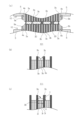
- FIG. 1(a) is a front view of a roll according to the present invention
- FIG. 1(b) is a sectional view of the roll according to the present invention
- FIG.1(c) is sectional drawing which shows other embodiment of the roll which concerns on this invention. The outline of the roll according to the present invention will be described below using these figures.
- the roll 10 removes liquids such as water, oil, or chemical components adhering to the surface to be cleaned of a steel plate, non-ferrous metal plate, resin plate, glass, paper, or film-like sheet, extracts, cleans, It is a roll for suction, and has a roll portion 1 and a base 2 .
- the roll part 1 is made of a nonwoven fabric and/or a synthetic resin porous body, and has a substantially annular shape. It is.
- the pedestal 2 has a substantially disk shape or a substantially circular ring shape, and has two flanges 4a and 4b that abut on the roll pieces at both ends, and the two flanges 4a and 4b each hold fasteners 9a and 9b.
- At least one side of the rotating shaft 5 is formed with a discharge hole 6 for discharging the liquid sucked from the roll portion 1 to the outside.
- a large number of holes 7 are formed in the outer peripheral surface of the rotary shaft 5 and communicate with the discharge holes 6 .
- the liquid in the roll portion 1 When used while connected to the suction device, the liquid in the roll portion 1 is discharged to the outside through the discharge hole 6, and the outer surface of the roll portion 1 has a plurality of steps along the longitudinal direction. 8 is formed, and the outer diameter of the flanges 4a and 4b is made smaller than the outer diameter of the roll piece 3a having a smaller outer diameter.
- uneven steps 8 are formed on the outer surface of the roll portion 1, and the outer diameter of the flanges 4a and 4b is larger than the outer diameter of the roll piece 3a having a smaller outer diameter.
- the two types of roll pieces 3a and 3b having different outer diameters can be deformed, and the contact area with the surface to be cleaned can be expanded, and the liquid can be absorbed. can be improved.
- the rotating shafts 15a and 15b of the base 12 are separated on the left and right, and a plurality of shafts 13a and 13b passing through the roll portion 11 are fixed to the flanges 14a and 14b.
- the present invention also includes this.
- a hollow portion 16b formed by inner rings of the roll pieces 3h and 3i communicates with a discharge hole 16a formed in one rotating shaft 15b.
- FIG. 2(a) is a perspective view showing the first embodiment of the roll piece and a reference view enlarging the inside.
- the roll piece 3a shown in this figure has a smaller outer diameter than the roll piece 3b shown in FIG.
- a non-woven fabric is used which is composed of voids occupying portions other than the non-woven fabric.
- the roll pieces having a small outer diameter can be made of a nonwoven fabric or a synthetic resin porous body, and the roll pieces having a large outer diameter can be made of a synthetic resin porous body.
- the elastic force is improved and the suction force is improved.
- the roll piece with a small outer diameter is made of non-woven fabric
- the overall shape is stable due to the rigidity of the non-woven fabric, and the roll piece with a large outer diameter is a synthetic resin porous material, so liquid adhering to the surface to be cleaned can be removed. It can be sucked efficiently.
- nonwoven fabrics can be produced by spraying, immersing, impregnating, or the like an elastic polymer compounded with a cross-linking agent on a formed body in which a plurality of fibers are accumulated in a flat plate shape and entangled in a three-dimensional manner, for example.
- a chemical bond method can be adopted in which the fibers are bonded by heating.
- a water flow entanglement method, a spunbond method, a meltblown method, a fiber bond method, a thermal bond method, or the like can be used as appropriate.
- Natural fibers such as cotton, rayon, and cellulose, and synthetic resin fibers such as polyester, nylon, and acrylic are used alone or in combination as fibers forming the non-woven fabric.
- Nitrile rubber, acrylic rubber, styrene rubber, urethane rubber, acrylic resin, urethane resin and the like are used alone or in combination for the polymeric elastic body.
- FIG. 2(b) is a perspective view showing a second embodiment of the roll piece and a reference view enlarging the inside.
- the roll piece 3b shown in this figure has a larger outer diameter than the roll piece 3a shown in FIG. It uses a sponge made up of synthetic fibers that occupy a large part of the body.
- the inner diameter of the circular hole portion 23 of the roll piece 3a and the inner diameter of the circular hole portion 24 of the roll piece 3b are made substantially the same.
- the roll piece having a large outer diameter of the roll portion constituting the present invention has a larger internal void ratio than the roll piece having a small outer diameter.
- the roll piece with a larger outer diameter that comes into contact with the surface to be cleaned first has a larger internal void ratio, a water channel is preferentially formed inside the roll piece with a larger outer diameter when liquid is sucked. , can efficiently aspirate liquids.
- the roll piece having a large outer diameter has a smaller length in the thickness direction than the roll piece having a small outer diameter.
- the internal porosity (porosity) of the synthetic resin porous body is preferably about 60-90%, and more preferably about 80-85%. By appropriately selecting the internal porosity according to the viscosity of the liquid, both the liquid suction efficiency and the durability can be improved.
- a method for producing a synthetic resin porous body includes, for example, immersing polyurethane in water, injecting carbon dioxide into the water, and using carbonic acid foaming to employ polyurethane that has been made porous with extremely fine bubbles. can be done.
- polyurethane nitrile rubber, acrylic rubber, styrene rubber, urethane rubber, acrylic resin, urethane resin and the like are used alone or in combination for the polymeric elastic body.
- Fig. 3 is a perspective view showing a state in which the roll according to the present invention is connected to a suction device.
- the upper and lower rolls 10, 10 are installed in a cleaning device 40 as a pair, and a constant pressure is applied to the rotating shaft 5 of the upper roll 10. , 18b to drive means 17a, 17b, and the drive means 17a, 17b rotate in the directions of the arrows, and between the upper roll 10 and the lower roll 10, both front and back surfaces and side surfaces are filled with moisture.
- a glass plate 30 to which a liquid such as a liquid is adhered is sent out in the direction of the white arrow.
- the insides of the rotating shafts 5, 5 are connected to a vacuum pump 22 via pipes 19a, 19b.
- the rolls 10, 10 positioned at the upper and lower portions remove liquid such as moisture from the front and back surfaces and side surfaces of the glass plate 30 and the edges of the holes 30a, 30b, 30c formed in the glass plate 30.
- FIG. 4(a) is a cross-sectional view showing the roll according to the present invention during work cleaning.
- the rolls 10, 10 remove liquid such as moisture from both the front and back surfaces and the side surfaces of the glass plate 30 and the edge of the hole formed in the glass plate
- the roll piece 3b with the larger outer diameter tilts and comes into contact with the front and back surfaces of the glass plate, or comes into contact with the edge of the hole.
- the end faces of the roll piece 3a having the smaller outer diameter come into contact with the front and back surfaces of the glass plate.
- the outer diameter of the flanges 4a and 4b is made smaller than the outer diameter of the roll piece 3a having a small outer diameter, two types of roll pieces 3a and 3b having different outer diameters can be deformed. It is possible to increase the contact area with the cleaning surface and improve the effect of absorbing the liquid.
- FIG. 4(b) is a sectional view showing the tilting of the roll piece of the roll section.
- a surface to be cleaned such as a glass plate is not shown.
- the outer peripheral end portions of the roll pieces 3o, 3o having a large outer diameter of the roll portion 101 are tilted, and the roll pieces 3o, 3o having a large outer diameter are tilted.
- the side surface of 3o and the end surfaces of roll pieces 3p, 3p, and 3p having small outer diameters are in contact with each other.
- a gap is less likely to occur between the surface to be cleaned and the outer surface of the roll portion 101, and the entire roll portion 101 can efficiently suck the liquid.
- FIG. 4(c) is a cross-sectional view showing another example of tilting of the roll piece of the roll section.
- a surface to be cleaned such as a glass plate is not shown.
- the roll portion 111 shown in this figure has a small diameter portion 36 formed by continuously stacking a plurality of roll pieces 3r having a small outer diameter when the roll portion 111 is in contact with the surface to be cleaned.
- the length X is set to be equal to or less than the half length Y of the difference in outer diameter from the roll piece 3q having a large outer diameter.
- the roll piece 3q having a large outer diameter may cover the entire small diameter portion 36.
- the liquid is also transmitted to the roll piece 3r with a small outer diameter, and the liquid can be efficiently sucked by the entire roll portion.
- the thickness of the roll piece 3r is the small diameter portion 36, and the above relationship of X ⁇ Y is established. is possible.
- FIG. 5(a) is a perspective view showing a third embodiment of the roll piece.
- a slit 28 is formed in the outer peripheral edge of the roll piece 3c shown in this figure.
- the roll piece 3c having the slit 28 formed at the outer peripheral edge can be applied to both a roll piece with a small outer diameter and a roll piece with a large outer diameter, but it is applied to a roll piece with a large outer diameter. As a result, it is possible to flexibly deform while following the shape of the surface to be cleaned, so that the surface to be cleaned can be prevented from being damaged.
- FIG. 5(b) is a perspective view showing a fourth embodiment of the roll piece.
- the roll piece 3d shown in this figure has a coating layer 29 formed on the entire side surface thereof, the coating layer 29 having lower liquid permeability than the synthetic resin porous body.
- a water channel is preferentially formed inside the roll piece having a large outer diameter, and the liquid can be efficiently sucked.
- a plurality of patterns can be applied to the combination of roll pieces having a large outer diameter and/or roll pieces having a small outer diameter and having coating layers 29 formed on the side surfaces thereof, as will be described later.
- FIG. 5(c) is a perspective view showing a fifth embodiment of the roll piece.
- the roll piece 3e shown in this figure has suction grooves 35 radially formed from the inner peripheral surface to the outer peripheral surface. As a result, the liquid can be efficiently sucked by applying the suction force from the suction device directly to the surface to be cleaned.
- FIG. 5(d) is a perspective view and a cross-sectional view along AA showing a sixth embodiment of the roll piece.
- a groove 32 is formed in the circumferential direction of the outer peripheral surface of the roll piece 3f shown in this figure. If this roll piece 3f is applied to a roll piece having a large outer diameter of the roll portion, even if the surface to be cleaned has unevenness, the roll piece having a large outer diameter can be brought into contact with the uneven portion. The contact area with the surface can be increased, and the effect of absorbing liquid can be improved.
- FIG. 5(e) is a perspective view and a BB sectional view showing a seventh embodiment of the roll piece.
- a roll piece 3g shown in this figure has an annular groove 33 formed on one side surface. If this roll piece 3g is applied to a roll piece having a large outer diameter of the roll portion, the roll piece having a large outer diameter can be easily tilted toward one side surface where the annular groove 33 is formed. Uniform suction performance can be exhibited.
- FIG. 5(f) is a perspective view showing an eighth embodiment of the roll piece.
- a roll piece 3h shown in this figure is a roll piece applied to the pedestal 12 described in FIG. is formed in
- FIG. 6(a) is a cross-sectional view showing a first embodiment of a roll section using a roll piece on which a coating layer is formed.
- roll pieces 3a having a small outer diameter and having no coating layer formed thereon and roll pieces 3i having a large outer diameter and having a coating layer formed on the right side of the drawing are alternately laminated.
- the water channel is preferentially formed inside the roll piece 3i having a large outer diameter, the liquid can be efficiently sucked.
- the rigidity of the roll piece 3i having a large outer diameter is improved, it is possible to suppress excessive tilting of the roll piece 3i when it comes into contact with the surface to be cleaned.
- FIG. 6(b) is a cross-sectional view showing a second embodiment of a roll section using a roll piece on which a coating layer is formed.
- the roll portion 31 shown in this figure has a small outer diameter roll piece 3a on which no coating layer is formed, and a coating layer formed on the portion in contact with the small outer diameter roll piece 3a on the right side in the drawing.
- This is an example in which roll pieces 3j having a large diameter are alternately laminated.
- the coating layer is not formed on the tip of the roll piece 3j having a large outer diameter, the liquid can be efficiently sucked without contact between the surface to be cleaned and the coating layer.
- the coating layer is formed on the portion in contact with the roll piece 3a with a small outer diameter, the water channel is preferentially formed inside the roll piece 3j with a large outer diameter, thereby efficiently sucking the liquid. can do.
- FIG. 6(c) is a cross-sectional view showing a third embodiment of a roll section using a roll piece on which a coating layer is formed.
- a coating layer is formed on a portion of the roll piece 3a having a small outer diameter on which no coating layer is formed and the portion of the roll piece 3a having a small outer diameter on the left and right sides in the drawing.
- This is an example in which roll pieces 3k having a large outer diameter are alternately laminated.
- a more limited water channel is formed inside the roll piece 3k having a large outer diameter, liquid can be efficiently sucked.
- FIG. 6(d) is a cross-sectional view showing a fourth embodiment of a roll section using a roll piece on which a coating layer is formed.
- the roll portion 51 shown in this figure has a large outer diameter roll piece 3b on which no coating layer is formed, and a coating layer formed on a portion of the roll piece 3b with a large outer diameter on the left side surface in the drawing.
- This is an example in which roll pieces 3l having a small diameter are alternately laminated.
- the water channel is preferentially formed inside the roll piece 3b having a large outer diameter, the liquid can be efficiently sucked.
- the rigidity of the roll piece 3l having a small outer diameter is improved, excessive tilting and denting can be suppressed when the roll piece 3l comes into contact with the surface to be cleaned. .
- FIG. 6(e) is a cross-sectional view showing a fifth embodiment of a roll section using a roll piece on which a coating layer is formed.
- a coating layer is formed on a portion of the roll piece 3b having a large outer diameter on which no coating layer is formed and the roll piece 3b having a large outer diameter on the left and right sides in the drawing.
- This is an example in which roll pieces 3m having a small outer diameter are alternately laminated.
- the rigidity of the roll piece 3m having a small outer diameter is further improved. dents can be suppressed, and liquid can be efficiently sucked.
- FIG. 6(f) is a cross-sectional view showing a sixth embodiment of a roll section using a roll piece on which a coating layer is formed.
- the roll portion 71 shown in this figure includes a roll piece 3l having a small outer diameter and a coating layer formed on a portion in contact with a roll piece 3j having a large outer diameter on the left side, and a roll piece 3l having a small outer diameter on the right side.
- This is an example in which roll pieces 3j with a large outer diameter in which a coating layer is formed in a portion in contact with the roll piece 3l with a small diameter are alternately laminated, and the coating layers of the roll piece 3j and the roll piece 3l are in contact with each other. .
- This embodiment combines the functions of both the roll piece 3j having a large outer diameter described in FIG. 6(b) and the roll piece 3l having a small outer diameter described in FIG. 6(d).
- the roll pieces support each other, and tilting and denting when contacting the surface to be cleaned can be suppressed, so liquid can be sucked more efficiently. can.
- FIG. 6(g) is a cross-sectional view showing a seventh embodiment of a roll section using a roll piece having a coating layer formed thereon.
- the roll portion 81 shown in this figure includes a roll piece 3n having a small outer diameter and a coating layer formed on a portion of the roll piece 3j having a large outer diameter on the right side of the drawing, and a roll piece 3n having a small outer diameter on the right side.
- This is an example in which roll pieces 3j having a large outer diameter and having a coating layer formed on the portions in contact with the roll pieces 3n having a small diameter are alternately laminated.
- FIG. 6(h) is a cross-sectional view showing an eighth embodiment of a roll section using a roll piece on which a coating layer is formed.
- the roll portion 91 shown in this figure includes a roll piece 3m having a small outer diameter and a coating layer formed in a portion in contact with a roll piece 3k having a large outer diameter on the left and right sides, and a roll piece 3m having a small outer diameter, and This is an example in which roll pieces 3k having a large outer diameter, in which a coating layer is formed in a portion in contact with the roll piece 3m having a small outer diameter, are alternately laminated, and the coating layers of the roll piece 3m and the roll piece 3k are in contact with each other. ing.
- This embodiment combines the functions of both the roll piece 3k with a large outer diameter in FIG. 6(c) and the roll piece 3m with a small outer diameter in FIG. By arranging them so as to contact each other, the roll pieces support each other, and compared with the roll portion 81 of FIG. Therefore, the liquid can be sucked more efficiently.
- the roll according to the present invention removes, extracts, cleans, and sucks liquids such as water, oil, or chemical components adhering to the surface to be cleaned of a steel plate, non-ferrous metal plate, resin plate, glass, paper, or film-like sheet. It is used as a role for
Landscapes
- Engineering & Computer Science (AREA)
- General Engineering & Computer Science (AREA)
- Mechanical Engineering (AREA)
- Cleaning In General (AREA)
- Rolls And Other Rotary Bodies (AREA)
Abstract
【課題】 被洗浄面への当接面積を拡大させることができると共に、水分等の液体を吸収する効果を向上させることができるロールを提供する。 【解決手段】 ロール10は、ロール部1及び台座2を有し、ロール部1は、不織布又は合成樹脂多孔質体からなり、略円環形状であると共に、外径が異なる2種類のロール片3a、3bが台座2の外周に積層されて形成されているものであって、台座2は、略円板形状又は略円環形状であると共に、両端のロール片3a、3aに当接する2枚のフランジ4a、4bと、2枚のフランジ4a、4bの各々が係止又は固定される回転軸5とを有し、少なくとも回転軸5の一方側には、排出孔6を有しており、ロール部1の外表面は、長手方向に沿って複数の段差8が形成されていると共に、フランジ4a、4bの外径を外径が小さいロール片3aの外径よりも小さくしている。
Description
本発明は、鋼板、非鉄金属板、樹脂板、ガラス、製紙、あるいはフィルム状のシートの被洗浄面に付着した水分、油分、あるいは薬品成分等の液体を除去、搾取、洗浄、吸引する為のロールに関するものである。
従来から、被洗浄面に付着した水分等を除去、搾取、洗浄、吸引する為のロールが知られている(特許文献1及び2)。
特許文献1に記載のロールは、一対の吸水性スポンジローラー間に水処理を施された部品を通し、該部品の表面に付着している水滴を除去するようにした水切り装置において、吸水性スポンジローラーの吸水性スポンジに、ローラー回転方向及びスラスト方向に多数のスリットを設けたものである。
また、特許文献2の図4及び図5には、不織布を大とし、ロール本体構成部材を小として溝部を形成した溝付不織布ロールが記載されており、表面平坦なゴムロールに対峙して設けることによって、搾出された水分等が溝部を流れて外部に排出され、不織布に含浸される水等の量を減少させるようにしたものである。
しかしながら、上記特許文献1に記載のロールは、柔らか過ぎることによって、被洗浄面に当接しない隙間が形成され易くなり、水分等を吸収する効果が十分ではないという課題を有していた。また、上記特許文献2に記載のロールは、溝部が水分等を排出する目的で形成されているものであって、被洗浄面への当接面積を拡大させることを意図しているものではないので、被洗浄面に形成されている穴部等の側面に付着している水分等の液体を吸収する効果が十分ではないという課題を有していた。
本発明は、前記従来の課題を解決するものであり、被洗浄面への当接面積を拡大させることができると共に、水分等の液体を吸収する効果を向上させることができるロールを提供することを目的とする。
前記従来の課題を解決するために、請求項1の発明は、鋼板、非鉄金属板、樹脂板、ガラス、製紙、あるいはフィルム状のシートの被洗浄面に付着した水分、油分、あるいは薬品成分等の液体を除去、搾取、洗浄、吸引する為のロールにおいて、前記ロールは、ロール部及び台座を有し、前記ロール部は、略円環形状であると共に、外径が異なる2種類のロール片が前記台座の外周に積層されて形成されているものであって、前記台座は、略円板形状又は略円環形状であると共に、両端の前記ロール片に当接する2枚のフランジと、該2枚のフランジの各々が係止又は固定される回転軸と、を有し、少なくとも前記回転軸の一方側には、排出孔を有しており、吸引装置に連結した状態の使用時において、前記ロール部内の液体が前記排出孔から外部に排出されるものであって、前記ロール部の外表面は、長手方向に沿って複数の段差が形成されていると共に、前記フランジの外径は、外径が小さいロール片の外径よりも小さいことを特徴としている。
請求項1の発明では、外径が異なる2種類のロール片を使用しているので、ロール部の外表面に凹凸の段差が形成されることとなり、且つ、フランジの外径が、外径が小さいロール片の外径よりも小さくなるようにしているので、外径が異なる2種類のロール片を変形させることができることとなり、被洗浄面への当接面積を拡大させることができると共に、液体を吸収する効果を向上させることができる。
請求項2の発明は、請求項1の発明において、ロール片は、不織布及び/又は合成樹脂多孔質体であることを特徴としている。これにより、外径の違いによらずロール片の全てを不織布のみ又は合成樹脂多孔質体のみで形成した場合は、均一性の高い吸引性能を発揮するロールを形成することができる。また、外径が異なるロール片の一方を不織布で形成し、他方を合成樹脂多孔質体で形成した場合には、不織布の剛性によりロールの全体形状が安定すると共に、合成樹脂多孔質体により被洗浄面に付着した液体の特性に合わせて効率よく吸引することができる。
請求項3の発明は、請求項1又は2の発明において、外径が大きいロール片は、外径が小さいロール片に対して内部空隙率が大きいことを特徴としている。これにより、被洗浄面に先に当接する外径の大きいロール片の方が内部空隙率が大きいため、液体を吸引する際に、外径の大きいロール片の内部に優先的に水路が形成され、効率よく液体を吸引することができる。
請求項4の発明は、請求項1~3のいずれかの発明において、外径が大きいロール片及び/又は外径の小さいロール片の側面に、合成樹脂多孔質体よりも通液性の低いコーティング層が形成されていることを特徴としている。これにより、液体を吸引する際に、外径が大きいロール片の内部により優先的に水路が形成され、効率よく液体を吸引することができる。また、ロール片の剛性が向上することで、被洗浄面と当接した際の過度な傾きや倒れを抑制できるため、隙間が生じにくくなり、液体を効率よく吸引することができる。
請求項5の発明は、請求項1~4のいずれかの発明において、外径が大きいロール片は、外径が小さいロール片に対して厚み方向の長さが小さいことを特徴としている。これにより、被洗浄面と先に当接する外径が大きいロール片の厚みが小さいため、被洗浄面と当接した際に屈曲しやすく柔軟に変形が可能なため、被洗浄面を傷つけるのを防止することができる。
請求項6の発明は、請求項1~5のいずれかの発明において、外径が大きいロール片の外周端部は、スリットが形成されていることを特徴としている。これにより、被洗浄面の形状に追従しながら柔軟に変形が可能となるため、さらに被洗浄面を傷つけるのを防止することができる。
請求項7の発明は、請求項1~6のいずれかの発明において、ロール部が被洗浄面と当接する使用時において、外径が大きいロール片の外周端部は傾倒すると共に、外径が大きいロール片の側面と外径が小さいロール片の端面とが当接することを特徴としている。これにより、使用時は、被洗浄面とロール部の外表面との間に隙間が生じにくくなり、ロール部全体として効率よく液体を吸引することができる。
請求項8の発明は、請求項7の発明において、外径が小さいロール片が1枚又は、複数枚が連続して積層されてなる径小部の厚み方向の長さは、外径が大きいロール片との外径差の半分の長さ以下であることを特徴としている。これにより、外径が大きいロール片が傾倒した時に、外径が小さいロール片の厚み(複数枚の場合は複数枚全体の厚み)の半分以上を覆うことで、外径が大きいロール片で効率よく吸引することができる。また、外径が大きいロール片は外径が小さいロール片の全体(径小部)を覆ってもよい。尚、外径が大きいロール片が傾倒すると液体は外径が小さいロール片にも伝達され、ロール部全体として効率よく液体を吸引することができる。
請求項9の発明は、請求項1~8のいずれかの発明において、ロール片は、内周面から外周面に至る吸引溝が放射状に形成されていることを特徴としている。これにより、吸引装置からの吸引力を直接、被洗浄面に作用させて効率よく液体を吸引することができる。
請求項10の発明は、請求項1~9のいずれかの発明において、外径が大きいロール片は、外周面の周方向に溝が形成されていることを特徴としている。これにより、被洗浄面に凹凸がある場合でも、該凹凸箇所に外径が大きいロール片を当接させることができるので、被洗浄面への当接面積を拡大させることができると共に、液体を吸収する効果を向上させることができる。
請求項11の発明は、請求項1~10のいずれかの発明において、外径が大きいロール片の一方の側面に、円環状の溝が形成されていることを特徴としている。これにより、外径が大きいロール片は、円環状の溝が形成されている一方の側面側に傾倒させ易くすることができ、均一な吸引性能を発揮させることができる。
請求項1のロールの発明は、被洗浄面への当接面積を拡大させることができると共に、水分等の液体を吸収する効果を向上させることができる。また、請求項2の発明は、弾性力が向上すると共に吸引力が向上する。また、全体形状が安定すると共に、被洗浄面に付着した液体を効率よく吸引することができる。
請求項3及び4の発明は、液体を吸引する際に、外径の大きいロール片の内部に優先的に水路が形成され、効率よく液体を吸引することができる。また、請求項5及び6の発明は、被洗浄面を傷つけるのを防止することができる。また、請求項7及び8の発明は、ロール全体として効率よく液体を吸引することができる。
請求項9の発明は、吸引装置からの吸引力を直接、被洗浄面に作用させて効率よく液体を吸引することができる。また、請求項10の発明は、被洗浄面への当接面積を拡大させることができると共に、液体を吸収する効果を向上させることができる。また、請求項11の発明は、均一な吸引性能を発揮させることができる。
以下、本発明の実施形態について、図面を参照しながら説明する。なお、この実施の形態によって本発明が限定されるものではない。図1(a)は、本発明に係るロールの正面図であり、図1(b)は、本発明に係るロールの断面図である。また、図1(c)は、本発明に係るロールの他の実施形態を示す断面図である。これらの図を用いて本発明に係るロールの概要について以下に説明する。
本発明に係るロール10は、鋼板、非鉄金属板、樹脂板、ガラス、製紙、あるいはフィルム状のシートの被洗浄面に付着した水分、油分、あるいは薬品成分等の液体を除去、搾取、洗浄、吸引する為のロールであり、ロール部1及び台座2を有している。
ロール部1は、不織布及び/又は合成樹脂多孔質体からなり、略円環形状であると共に、外径が異なる2種類のロール片3a、3bが台座2の外周に積層されて形成されているものである。
台座2は、略円板形状又は略円環形状であると共に、両端のロール片に当接する2枚のフランジ4a、4bと、この2枚のフランジ4a、4bの各々が止め金具9a、9bを介して係止又は固定される回転軸5とを有しており、少なくとも回転軸5の一方側には、ロール部1から吸引した液体を外部へと排出する排出孔6が形成されている。また、回転軸5の外周面には多数の孔部7が形成されており、この孔部7が排出孔6に連通している。
そして、吸引装置に連結した状態の使用時において、ロール部1内の液体が排出孔6から外部に排出されるものであって、ロール部1の外表面は、長手方向に沿って複数の段差8が形成されていると共に、フランジ4a、4bの外径を、外径が小さいロール片3aの外径よりも小さくしている。
上記のよう構成されたロール10は、ロール部1の外表面に凹凸の段差8が形成されることとなり、且つ、フランジ4a、4bの外径が、外径が小さいロール片3aの外径よりも小さくなるようにしているので、外径が異なる2種類のロール片3a、3bを変形させることができることとなり、被洗浄面への当接面積を拡大させることができると共に、液体を吸収する効果を向上させることができる。
尚、図1(c)に示すロール20のように、台座12の回転軸15a、15bが左右で分離しており、ロール部11を貫通する複数のシャフト13a、13bがフランジ14a、14bに固定されている形態であってもよく、これも本発明に含まれる。この場合には、ロール片3h、3iの内環によって形成される空洞部16bが一方の回転軸15bに形成された排出孔16aと連通している。
図2(a)は、ロール片の第1実施形態を示す斜視図及び内部を拡大した参考図である。この図に示すロール片3aは、図2(b)に示すロール片3bよりも小さい外径のロール片を示しており、繊維25と、繊維同士を接着するバインダー26と、繊維25及びバインダー26以外の部分を占める空隙部とで構成された不織布を使用している。尚、本発明を構成するロール部は、外径が小さいロール片を不織布又は合成樹脂多孔質体として、外径が大きいロール片を合成樹脂多孔質体とすることができる。これにより、外径の違いによらずロール片の全てを合成樹脂多孔質体で形成した場合は弾性力が向上すると共に吸引力が向上する。一方で外径が小さいロール片を不織布で形成した場合には、不織布の剛性により全体形状が安定すると共に、外径の大きいロール片は合成樹脂多孔質体のため被洗浄面に付着した液体を効率よく吸引することができる。
また、不織布の製造方法は、例えば複数本の繊維を平板状に集積し3次元に絡合させた形成体にたいして、架橋剤を配合した高分子弾性体をスプレー、浸漬、含浸等の方法を用いて付着させ、加熱することにより繊維の間を結合させるケミカルボンド法を採用することができる。他には、水流絡合法、スパンボンド法、メルトブロー法、ファイバーボンド法やサーマルボンド法等を適宜採用することができる。また、不織布を形成する繊維には、綿、レーヨン、セルロース等の天然繊維、ポリエステル、ナイロン、アクリル等の合成樹脂繊維が単独使用、あるいは併用される。高分子弾性体には、ニトリルゴム、アクリルゴム、スチレンゴム、ウレタンゴム、アクリル樹脂、ウレタン樹脂等が単独使用、あるいは併用される。
図2(b)は、ロール片の第2実施形態を示す斜視図及び内部を拡大した参考図である。この図に示すロール片3bは、図2(a)に示すロール片3aよりも大きい外径のロール片を示しており、連続気泡27aと、単独気泡27bと、連続気泡27a及び単独気泡27b以外の部分を占める合成繊維とで構成されたスポンジを使用している。尚、ロール片3aの円孔部23の内径と、ロール片3bの円孔部24の内径は略同一となるようにしている。尚、本発明を構成するロール部の外径が大きいロール片は、外径が小さいロール片に対して内部空隙率を大きくするのが好ましい。これにより、被洗浄面に先に当接する外径の大きいロール片の方が内部空隙率が大きいため、液体を吸引する際に、外径の大きいロール片の内部に優先的に水路が形成され、効率よく液体を吸引することができる。また、外径が大きいロール片は、外径が小さいロール片に対して厚み方向の長さを小さくするのが好ましい。これにより、被洗浄面と先に当接する外径が大きいロール片の厚みが小さいため、被洗浄面と当接した際に屈曲しやすく柔軟に変形が可能なため、被洗浄面を傷つけるのを防止することができる。
また、合成樹脂多孔質体の内部空隙率(気孔率)は約60~90%が好ましく、最適には約80~85%が更に好ましい。液体の粘性等により内部空隙率を適宜選択することで、液体の吸引効率と耐久性を共に向上させることができる。
また、合成樹脂多孔質体の製造方法は、例えばポリウレタンを水中に浸漬させると共に、水中に二酸化炭素を注入し、炭酸発泡させることで極微細な気泡を有する多孔質化されたポリウレタンを採用することができる。高分子弾性体にはポリウレタン以外にも、ニトリルゴム、アクリルゴム、スチレンゴム、ウレタンゴム、アクリル樹脂、ウレタン樹脂等が単独使用、あるいは併用される。
図3は、本発明に係るロールを吸引装置に連結した状態を示す斜視図である。ロール10、10は、洗浄装置40に上下一対で設置され、上部に位置するロール10の回転軸5に一定の圧力が加えられ、上下のロール10、10は、回転軸5、5がジョイント18a、18bを介して駆動手段17a、17bに連結され、この駆動手段17a、17bによって、矢印の方向に回転駆動し、上部のロール10と下部のロール10の間を、表裏の両面及び側面に水分等の液体が付着したガラス板30が白抜き矢印の方向に送出されている。また、回転軸5、5の内部は、配管19a、19bを介して真空ポンプ22に連接されている。上部及下部に位置するロール10、10は、ガラス板30の表裏の両面と側面及びガラス板30に形成されている穴部30a、30b、30cの縁から水分等の液体を除去する。
上記の如くのロール10、10の状態において、真空ポンプ22を稼働して真空吸引力を作用させると、ロール部に負圧が付加され、ロール部に吸収された液体は、回転軸5、5の内部に形成された排出孔から配管19a、19bを通り、ロール10、10の外部に吸引されて、排出される。
図4(a)は、本発明に係るロールのワーク洗浄時を示す断面図である。ロール10、10は、ガラス板30の表裏の両面と側面及びガラス板に形成されている穴部の縁から水分等の液体を除去する際に、外径が大きい方のロール片3bは、先端が傾倒してガラス板の表面及び裏面に当接するか、穴部の縁に当接することとなる。また、外径が小さいほうのロール片3aの端面はガラス板の表面及び裏面に当接することとなる。また、フランジ4a、4bの外径を、外径が小さいロール片3aの外径よりも小さくしているので、外径が異なる2種類のロール片3a、3bを変形させることができることとなり、被洗浄面への当接面積を拡大させることができると共に、液体を吸収する効果を向上させることができる。
図4(b)は、ロール部のロール片の傾倒を示す断面図である。尚、ガラス板等の被清掃面は図示していない。この図に示すように、ロール部が被洗浄面と当接する使用時において、ロール部101の外径が大きいロール片3o、3oの外周端部は傾倒すると共に、外径が大きいロール片3o、3oの側面と外径が小さいロール片3p、3p、3pの端面とが当接している。これにより、使用時は、被洗浄面とロール部101の外表面との間に隙間が生じにくくなり、ロール部101全体として効率よく液体を吸引することができる。
図4(c)は、ロール部のロール片の傾倒の他例を示す断面図である。尚、ガラス板等の被清掃面は図示していない。この図に示すロール部111は、ロール部111が被洗浄面と当接する使用時において、外径が小さいロール片3rの複数枚が連続して積層されてなる径小部36の厚み方向の長さXを、外径が大きいロール片3qとの外径差の半分の長さY以下となるようにしている。これにより、外径が大きいロール片3qが傾倒した時に、径小部36の半分以上を覆うことで、外径が大きいロール片3qで効率よく吸引することができる。また、図4(c)に示すように、外径が大きいロール片3qは径小部36の全体を覆ってもよい。尚、外径が大きいロール片3qが傾倒すると液体は外径が小さいロール片3rにも伝達され、ロール部全体として効率よく液体を吸引することができる。また、外径が大きいロール片3q、3qに挟まれる外径が小さいロール片3rが1枚の場合であっても、その厚みを径小部36として、上記X≦Yの関係を成立させることは可能である。
図5(a)は、ロール片の第3実施形態を示す斜視図である。この図に示すロール片3cの外周端部にはスリット28が形成されている。尚、外周端部にスリット28が形成されたロール片3cは、外径が小さいロール片と外径が大きいロール片のどちらにも適用することができるが、外径が大きいロール片に適用することによって、被洗浄面の形状に追従しながら柔軟に変形が可能となるため、被洗浄面を傷つけるのを防止することができる。
図5(b)は、ロール片の第4実施形態を示す斜視図である。この図に示すロール片3dは、側面全体に、合成樹脂多孔質体よりも通液性の低いコーティング層29が形成されている。これにより、液体を吸引する際に、外径が大きいロール片の内部により優先的に水路が形成され、効率よく液体を吸引することができる。尚、側面にコーティング層29が形成されている外径が大きいロール片及び/又は外径の小さいロール片の組み合わせは、後述するように複数のパターンを適用することができる。
図5(c)は、ロール片の第5実施形態を示す斜視図である。この図に示すロール片3eは、内周面から外周面に至る吸引溝35が放射状に形成されている。これにより、吸引装置からの吸引力を直接、被洗浄面に作用させて効率よく液体を吸引することができる。
図5(d)は、ロール片の第6実施形態を示す斜視図及びA-A断面図である。この図に示すロール片3fは、外周面の周方向に溝32が形成されている。このロール片3fをロール部の外径の大きいロール片に適用すれば、被洗浄面に凹凸がある場合でも、該凹凸箇所に外径が大きいロール片を当接させることができるので、被洗浄面への当接面積を拡大させることができると共に、液体を吸収する効果を向上させることができる。
図5(e)は、ロール片の第7実施形態を示す斜視図及びB-B断面図である。この図に示すロール片3gは、一方の側面に、円環状の溝33が形成されている。このロール片3gをロール部の外径の大きいロール片に適用すれば、外径が大きいロール片は、円環状の溝33が形成されている一方の側面側に傾倒させ易くすることができ、均一な吸引性能を発揮させることができる。
図5(f)は、ロール片の第8実施形態を示す斜視図である。この図に示すロール片3hは、図1(c)で説明した台座12に適用されるロール片であり、シャフト13a、13bが貫通する複数の貫通孔34、34・・がロール片3hの側面に形成されている。
図6(a)は、コーティング層が形成されたロール片を使用したロール部の第1実施形態を示す断面図である。この図に示すロール部21は、コーティング層が形成されていない外径が小さいロール片3aと、図面上、右側面にコーティング層が形成されている外径が大きいロール片3iを交互に積層した例である。本実施形態により、外径が大きいロール片3iの内部により優先的に水路が形成されるため、効率よく液体を吸引することができる。また、外径が大きいロール片3iの剛性が向上することで、被洗浄面と当接した際に過度な倒れを抑制できるため、隙間が生じにくくなり、液体を効率よく吸引することができる。
図6(b)は、コーティング層が形成されたロール片を使用したロール部の第2実施形態を示す断面図である。この図に示すロール部31は、コーティング層が形成されていない外径が小さいロール片3aと、図面上、右側面の外径が小さいロール片3aと接する部分にコーティング層が形成されている外径が大きいロール片3jを交互に積層した例である。本実施形態により、外径が大きいロール片3jの先端部にはコーティング層が形成されていないため、被洗浄面とコーティング層とが当接することなく、効率よく液体を吸引することができる。一方で、外径が小さいロール片3aと接する部分にはコーティング層が形成されているため、外径が大きいロール片3jの内部により優先的に水路が形成されることで、効率よく液体を吸引することができる。
図6(c)は、コーティング層が形成されたロール片を使用したロール部の第3実施形態を示す断面図である。この図に示すロール部41は、コーティング層が形成されていない外径が小さいロール片3aと、図面上、左右の側面の外径が小さいロール片3aと接する部分にコーティング層が形成されている外径が大きいロール片3kを交互に積層した例である。本実施形態により、外径が大きいロール片3kの内部に、より限定的な水路が形成されるため、効率よく液体を吸引することができる。
図6(d)は、コーティング層が形成されたロール片を使用したロール部の第4実施形態を示す断面図である。この図に示すロール部51は、コーティング層が形成されていない外径が大きいロール片3bと、図面上、左側面の外径が大きいロール片3bと接する部分にコーティング層が形成されている外径が小さいロール片3lを交互に積層した例である。本実施形態により、外径が大きいロール片3bの内部により優先的に水路が形成されるため、効率よく液体を吸引することができる。また、外径が小さいロール片3lの剛性が向上するため、被洗浄面と当接した際に過度な傾きや凹みを抑制できるため、隙間が生じにくくなり、液体を効率よく吸引することができる。
図6(e)は、コーティング層が形成されたロール片を使用したロール部の第5実施形態を示す断面図である。この図に示すロール部61は、コーティング層が形成されていない外径が大きいロール片3bと、図面上、左右の側面の外径が大きいロール片3bと接する部分にコーティング層が形成されている外径が小さいロール片3mを交互に積層した例である。本実施形態は、図6(d)の外径が小さいロール片3lと比較して、外径が小さいロール片3mの剛性が更に向上するため、被洗浄面と当接した際に過度な傾きや凹みを抑制でき、更に液体を効率よく吸引することができる。
図6(f)は、コーティング層が形成されたロール片を使用したロール部の第6実施形態を示す断面図である。この図に示すロール部71は、図面上、左側面の外径が大きいロール片3jと接する部分にコーティング層が形成されている外径が小さいロール片3lと、図面上、右側面の外径が小さいロール片3lと接する部分にコーティング層が形成されている外径が大きいロール片3jを交互に積層した例であり、ロール片3jとロール片3lのコーティング層同士が接する状態となっている。本実施形態は、図6(b)で説明した外径が大きいロール片3jと、図6(d)で説明した外径が小さいロール片3lとの両方の機能を兼ね備えたものであり、更に各々のコーティング層同士を接するように配置することで、互いのロール片同士は支え合い、被洗浄面と当接した際の傾きや凹みをより抑制できため、更に液体を効率よく吸引することができる。
図6(g)は、コーティング層が形成されたロール片を使用したロール部の第7実施形態を示す断面図である。この図に示すロール部81は、図面上、右側面の外径が大きいロール片3jと接する部分にコーティング層が形成されている外径が小さいロール片3nと、図面上、右側面の外径が小さいロール片3nと接する部分にコーティング層が形成されている外径が大きいロール片3jを交互に積層した例である。本実施形態は、図6(b)で説明した外径が大きいロール片3jと、図6(d)で説明した外径が小さいロール片3lのコーティング層が、図面上、右側面に形成されたものとで構成されており、基本的な機能は先の説明の通りであるが、ロール全体としてコーティング層が略均等に配置されることとなるため、ロール全体の形状を安定させることができる。
図6(h)は、コーティング層が形成されたロール片を使用したロール部の第8実施形態を示す断面図である。この図に示すロール部91は、図面上、左右の側面の外径が大きいロール片3kと接する部分にコーティング層が形成されている外径が小さいロール片3mと、図面上、左右の側面の外径が小さいロール片3mと接する部分にコーティング層が形成されている外径が大きいロール片3kを交互に積層した例であり、ロール片3mとロール片3kのコーティング層同士が接する状態となっている。本実施形態は、図6(c)の外径が大きいロール片3kと、図6(e)の外径が小さいロール片3mとの両方の機能を兼ね備えたものであり、更に各々のコーティング層同士を接するように配置することで、互いのロール片同士は支え合い、図6(f)のロール部81と比較して、更に被洗浄面と当接した際の傾きや凹みをより抑制できため、更に液体を効率よく吸引することができる。
本発明に係るロールは、鋼板、非鉄金属板、樹脂板、ガラス、製紙、あるいはフィルム状のシートの被洗浄面に付着した水分、油分、あるいは薬品成分等の液体を除去、搾取、洗浄、吸引する為のロールとして利用される。
1、11、21、31、41、51、61、71、81、91、101、111 ロール部
2、12 台座
3a、3b、3c、3d、3e、3f、3g、3h、3i、3j、3k、3l、3m、3n、3o、3p、3q、3r ロール片
4a、4b、14a、14b フランジ
5、15a、15b 回転軸
6、16a 排出孔
7 孔部
8 段差
9a、9b 止め金具
10、20 ロール
13a、13b シャフト
16b 空洞部
17a、17b 駆動手段
18a、18b ジョイント
19a、19b 配管
22 真空ポンプ
23、24 円孔部
28 スリット
29 コーティング層
30 ガラス板
32 溝
33 円環状の溝
34 貫通孔
35 吸引溝
36 径小部
40 洗浄装置
2、12 台座
3a、3b、3c、3d、3e、3f、3g、3h、3i、3j、3k、3l、3m、3n、3o、3p、3q、3r ロール片
4a、4b、14a、14b フランジ
5、15a、15b 回転軸
6、16a 排出孔
7 孔部
8 段差
9a、9b 止め金具
10、20 ロール
13a、13b シャフト
16b 空洞部
17a、17b 駆動手段
18a、18b ジョイント
19a、19b 配管
22 真空ポンプ
23、24 円孔部
28 スリット
29 コーティング層
30 ガラス板
32 溝
33 円環状の溝
34 貫通孔
35 吸引溝
36 径小部
40 洗浄装置
Claims (11)
- 鋼板、非鉄金属板、樹脂板、ガラス、製紙、あるいはフィルム状のシートの被洗浄面に付着した水分、油分、あるいは薬品成分等の液体を除去、搾取、洗浄、吸引する為のロールにおいて、
前記ロールは、ロール部及び台座を有し、
前記ロール部は、略円環形状であると共に、外径が異なる2種類のロール片が前記台座の外周に積層されて形成されているものであって、
前記台座は、略円板形状又は略円環形状であると共に、両端の前記ロール片に当接する2枚のフランジと、該2枚のフランジの各々が係止又は固定される回転軸と、を有し、
少なくとも前記回転軸の一方側には、排出孔を有しており、吸引装置に連結した状態の使用時において、前記ロール部内の液体が前記排出孔から外部に排出されるものであって、
前記ロール部の外表面は、長手方向に沿って複数の段差が形成されていると共に、前記フランジの外径は、外径が小さいロール片の外径よりも小さいことを特徴とするロール - ロール片は、不織布及び/又は合成樹脂多孔質体であることを特徴とする請求項1に記載のロール
- 外径が大きいロール片は、外径が小さいロール片に対して内部空隙率が大きいことを特徴とする請求項1又は2に記載のロール
- 外径が大きいロール片及び/又は外径の小さいロール片の側面に、合成樹脂多孔質体よりも通液性の低いコーティング層が形成されていることを特徴とする請求項1~3のいずれか1項に記載のロール
- 外径が大きいロール片は、外径が小さいロール片に対して厚み方向の長さが小さいことを特徴とする請求項1~4のいずれか1項に記載のロール
- 外径が大きいロール片の外周端部は、スリットが形成されていることを特徴とする請求項1~5のいずれか1項に記載のロール
- ロール部が被洗浄面と当接する使用時において、
外径が大きいロール片の外周端部は傾倒すると共に、外径が大きいロール片の側面と外径が小さいロール片の端面とが当接することを特徴とする請求項1~6のいずれか1項に記載のロール - 外径が小さいロール片が1枚又は、複数枚が連続して積層されてなる径小部の厚み方向の長さは、外径が大きいロール片との外径差の半分の長さ以下であることを特徴とする請求項7に記載のロール
- ロール片は、内周面から外周面に至る吸引溝が放射状に形成されていることを特徴とする請求項1~8のいずれか1項に記載のロール
- 外径が大きいロール片は、外周面の周方向に溝が形成されていることを特徴とする請求項1~9のいずれか1項に記載のロール
- 外径が大きいロール片の一方の側面に、円環状の溝が形成されていることを特徴とする請求項1~10のいずれか1項に記載のロール
Applications Claiming Priority (2)
| Application Number | Priority Date | Filing Date | Title |
|---|---|---|---|
| JP2022005143A JP7803516B2 (ja) | 2022-01-17 | 2022-01-17 | ロール |
| JP2022-005143 | 2022-01-17 |
Publications (1)
| Publication Number | Publication Date |
|---|---|
| WO2023136348A1 true WO2023136348A1 (ja) | 2023-07-20 |
Family
ID=87279293
Family Applications (1)
| Application Number | Title | Priority Date | Filing Date |
|---|---|---|---|
| PCT/JP2023/001029 Ceased WO2023136348A1 (ja) | 2022-01-17 | 2023-01-16 | ロール |
Country Status (2)
| Country | Link |
|---|---|
| JP (1) | JP7803516B2 (ja) |
| WO (1) | WO2023136348A1 (ja) |
Citations (5)
| Publication number | Priority date | Publication date | Assignee | Title |
|---|---|---|---|---|
| JPS5687181U (ja) * | 1979-12-05 | 1981-07-13 | ||
| JPH1118838A (ja) * | 1997-07-01 | 1999-01-26 | Supiide Fuamu Clean Syst Kk | スクラブ洗浄用円板形ブラシ |
| JP2007098374A (ja) * | 2005-09-30 | 2007-04-19 | Kowa Co Ltd | ロール |
| JP2010188218A (ja) * | 2009-02-16 | 2010-09-02 | Kowa Co Ltd | ロール及び洗浄装置 |
| JP2013133877A (ja) * | 2011-12-27 | 2013-07-08 | Kowa Co Ltd | ロール及び洗浄装置 |
-
2022
- 2022-01-17 JP JP2022005143A patent/JP7803516B2/ja active Active
-
2023
- 2023-01-16 WO PCT/JP2023/001029 patent/WO2023136348A1/ja not_active Ceased
Patent Citations (5)
| Publication number | Priority date | Publication date | Assignee | Title |
|---|---|---|---|---|
| JPS5687181U (ja) * | 1979-12-05 | 1981-07-13 | ||
| JPH1118838A (ja) * | 1997-07-01 | 1999-01-26 | Supiide Fuamu Clean Syst Kk | スクラブ洗浄用円板形ブラシ |
| JP2007098374A (ja) * | 2005-09-30 | 2007-04-19 | Kowa Co Ltd | ロール |
| JP2010188218A (ja) * | 2009-02-16 | 2010-09-02 | Kowa Co Ltd | ロール及び洗浄装置 |
| JP2013133877A (ja) * | 2011-12-27 | 2013-07-08 | Kowa Co Ltd | ロール及び洗浄装置 |
Also Published As
| Publication number | Publication date |
|---|---|
| JP7803516B2 (ja) | 2026-01-21 |
| JP2023104265A (ja) | 2023-07-28 |
Similar Documents
| Publication | Publication Date | Title |
|---|---|---|
| TWI435768B (zh) | And a functional roller having a grid-like gas-liquid conduction path structure | |
| US20120064809A1 (en) | Tufted buffing pad | |
| CN106388731A (zh) | 一种复合式环形清洁带 | |
| JP4652459B2 (ja) | ロール及び洗浄装置 | |
| WO2023136348A1 (ja) | ロール | |
| JP5511044B2 (ja) | ロール | |
| JP2008291958A (ja) | ロール | |
| JP5455105B2 (ja) | ロール及び洗浄装置 | |
| JPH07120145A (ja) | 不織布ロールを利用する吸液方法と、この吸液方法に使用する吸液ロール | |
| WO2024257831A1 (ja) | ロール | |
| KR101021091B1 (ko) | 피브이에이 폴리우레탄폼 클린패드 제조방법 및 그클린패드 | |
| JP4738980B2 (ja) | ロール | |
| KR102010829B1 (ko) | 물 또는 액상 청소용제를 이용하는 청소기용 청소패드 | |
| JP2023150536A (ja) | ロール | |
| JP4739109B2 (ja) | ロール | |
| JP2012193787A (ja) | ロール及び洗浄装置 | |
| JPH0515856A (ja) | オイルプロセスライン等で採用される流体均一排除機能を備えた複合構造ゴムリンガーロール | |
| CN102962216B (zh) | 辊以及辊组件 | |
| ES2867397T3 (es) | Rodillo recubierto no tejido | |
| CN217137921U (zh) | 适用于清洁机器人的用于擦拭待清洁工作面的拖布 | |
| JP5930706B2 (ja) | ロール及び洗浄装置 | |
| JP5447918B2 (ja) | ロール及び洗浄装置 | |
| JP2010276058A (ja) | ロール及び洗浄装置 | |
| JP5240961B2 (ja) | ロール及び洗浄装置 | |
| KR101111417B1 (ko) | 롤 |
Legal Events
| Date | Code | Title | Description |
|---|---|---|---|
| 121 | Ep: the epo has been informed by wipo that ep was designated in this application |
Ref document number: 23740356 Country of ref document: EP Kind code of ref document: A1 |
|
| NENP | Non-entry into the national phase |
Ref country code: DE |
|
| 122 | Ep: pct application non-entry in european phase |
Ref document number: 23740356 Country of ref document: EP Kind code of ref document: A1 |