WO2023136133A1 - 車両用シート装置 - Google Patents
車両用シート装置 Download PDFInfo
- Publication number
- WO2023136133A1 WO2023136133A1 PCT/JP2022/048147 JP2022048147W WO2023136133A1 WO 2023136133 A1 WO2023136133 A1 WO 2023136133A1 JP 2022048147 W JP2022048147 W JP 2022048147W WO 2023136133 A1 WO2023136133 A1 WO 2023136133A1
- Authority
- WO
- WIPO (PCT)
- Prior art keywords
- link
- seat
- seat cushion
- respect
- vehicle
- Prior art date
- Legal status (The legal status is an assumption and is not a legal conclusion. Google has not performed a legal analysis and makes no representation as to the accuracy of the status listed.)
- Ceased
Links
Images







Classifications
-
- A—HUMAN NECESSITIES
- A47—FURNITURE; DOMESTIC ARTICLES OR APPLIANCES; COFFEE MILLS; SPICE MILLS; SUCTION CLEANERS IN GENERAL
- A47C—CHAIRS; SOFAS; BEDS
- A47C1/00—Chairs adapted for special purposes
- A47C1/02—Reclining or easy chairs
- A47C1/022—Reclining or easy chairs having independently-adjustable supporting parts
- A47C1/024—Reclining or easy chairs having independently-adjustable supporting parts the parts, being the back-rest, or the back-rest and seat unit, having adjustable inclination
- A47C1/025—Reclining or easy chairs having independently-adjustable supporting parts the parts, being the back-rest, or the back-rest and seat unit, having adjustable inclination by means of a rack-and-pinion or like gearing mechanism
-
- A—HUMAN NECESSITIES
- A47—FURNITURE; DOMESTIC ARTICLES OR APPLIANCES; COFFEE MILLS; SPICE MILLS; SUCTION CLEANERS IN GENERAL
- A47C—CHAIRS; SOFAS; BEDS
- A47C7/00—Parts, details, or accessories of chairs or stools
- A47C7/02—Seat parts
-
- A—HUMAN NECESSITIES
- A47—FURNITURE; DOMESTIC ARTICLES OR APPLIANCES; COFFEE MILLS; SPICE MILLS; SUCTION CLEANERS IN GENERAL
- A47C—CHAIRS; SOFAS; BEDS
- A47C7/00—Parts, details, or accessories of chairs or stools
- A47C7/50—Supports for the feet or the legs
-
- B—PERFORMING OPERATIONS; TRANSPORTING
- B60—VEHICLES IN GENERAL
- B60N—SEATS SPECIALLY ADAPTED FOR VEHICLES; VEHICLE PASSENGER ACCOMMODATION NOT OTHERWISE PROVIDED FOR
- B60N2/00—Seats specially adapted for vehicles; Arrangement or mounting of seats in vehicles
- B60N2/02—Seats specially adapted for vehicles; Arrangement or mounting of seats in vehicles the seat or part thereof being movable, e.g. adjustable
- B60N2/04—Seats specially adapted for vehicles; Arrangement or mounting of seats in vehicles the seat or part thereof being movable, e.g. adjustable the whole seat being movable
- B60N2/06—Seats specially adapted for vehicles; Arrangement or mounting of seats in vehicles the seat or part thereof being movable, e.g. adjustable the whole seat being movable slidable
-
- B—PERFORMING OPERATIONS; TRANSPORTING
- B60—VEHICLES IN GENERAL
- B60N—SEATS SPECIALLY ADAPTED FOR VEHICLES; VEHICLE PASSENGER ACCOMMODATION NOT OTHERWISE PROVIDED FOR
- B60N2/00—Seats specially adapted for vehicles; Arrangement or mounting of seats in vehicles
- B60N2/02—Seats specially adapted for vehicles; Arrangement or mounting of seats in vehicles the seat or part thereof being movable, e.g. adjustable
- B60N2/04—Seats specially adapted for vehicles; Arrangement or mounting of seats in vehicles the seat or part thereof being movable, e.g. adjustable the whole seat being movable
- B60N2/16—Seats specially adapted for vehicles; Arrangement or mounting of seats in vehicles the seat or part thereof being movable, e.g. adjustable the whole seat being movable height-adjustable
-
- B—PERFORMING OPERATIONS; TRANSPORTING
- B60—VEHICLES IN GENERAL
- B60N—SEATS SPECIALLY ADAPTED FOR VEHICLES; VEHICLE PASSENGER ACCOMMODATION NOT OTHERWISE PROVIDED FOR
- B60N2/00—Seats specially adapted for vehicles; Arrangement or mounting of seats in vehicles
- B60N2/02—Seats specially adapted for vehicles; Arrangement or mounting of seats in vehicles the seat or part thereof being movable, e.g. adjustable
- B60N2/22—Seats specially adapted for vehicles; Arrangement or mounting of seats in vehicles the seat or part thereof being movable, e.g. adjustable the back-rest being adjustable
-
- B—PERFORMING OPERATIONS; TRANSPORTING
- B60—VEHICLES IN GENERAL
- B60N—SEATS SPECIALLY ADAPTED FOR VEHICLES; VEHICLE PASSENGER ACCOMMODATION NOT OTHERWISE PROVIDED FOR
- B60N3/00—Arrangements or adaptations of other passenger fittings, not otherwise provided for
- B60N3/06—Arrangements or adaptations of other passenger fittings, not otherwise provided for of footrests
Definitions
- the present invention relates to a vehicle seat device capable of adjusting the height of a vehicle seat.
- a vehicle seat device capable of adjusting the height of a vehicle seat
- a vehicle seat lifter and a vehicle clutch unit disclosed in Patent Document 1 below are known.
- the vehicle seat lifter includes a sector gear that meshes with a pinion gear of a vehicle clutch unit and a link mechanism, and is configured such that each link member of the link mechanism tilts when the sector gear rotates according to the rotation of the pinion gear.
- the height of the vehicle seat is adjusted according to the tilting of each link member.
- a vehicle clutch unit is configured to include various mechanical members such as an operation lever, an input-side clutch, and an output-side clutch, in addition to an output shaft member on which a pinion gear is formed.
- the input-side clutch transmits the rotation of the operating lever to the output-side clutch by rotating the input-side inner ring member, the input-side outer ring member, and the input-side transmission member with the rotation of the operating lever.
- the rotation of the operating lever is input to the output side clutch, and during the return operation in which the operating lever is returned to the neutral position after being driven, the operating lever is moved to the neutral position while maintaining the rotational position of the output shaft member.
- the output side clutch restricts rotation of the output shaft member due to force input to the output shaft member from the vehicle seat side, and allows rotation of the output shaft member when rotation of the operating lever is transmitted by the input side clutch. is configured as
- the present invention has been made to solve the above-mentioned problems, and its object is to control the tilting of a link using a round unit, thereby increasing the height of a vehicle seat in a space-saving manner. To provide an adjustable configuration.
- brackets (12a, 12b) for supporting the vehicle seat (11); base members (25a, 25b) arranged below the bracket; a link mechanism (30) capable of adjusting the height of the bracket with respect to the base member;
- a vehicle seat device (10) comprising: The link mechanism is a first link (31, 33) having one side end (31a) tiltably connected to the bracket; second links (32, 34) having one side end (32a) tiltably connected to the base member; connecting the other side end portion (31b) of the first link and the other side end portion (32b) of the second link to change the connection angle ( ⁇ ) between the first link and the second link; a round unit (40a, 40b) for changing the height of the bracket with respect to the base member; has The round unit is a shaft (42, 112) and a locking member (53, 54, 55, 150); two plates (51, 52, 141, 142) attached to the other side end of the first link and the other
- the invention of claim 2 is brackets (12a, 12b) for supporting the vehicle seat (11); base members (25a, 25b) arranged below the bracket; a link mechanism (30) capable of adjusting the height of the bracket with respect to the base member;
- a vehicle seat device (10) comprising: The link mechanism is a first link (31, 33); second links (32, 34) having one side end tiltably connected to the base member and the other side end connected to the first link so as to change the connection angle;
- a round unit (40a) which is connected to one side end of the first link and the bracket and changes the height of the bracket with respect to the base member by changing the connection angle between the first link and the second link.
- the round unit is a shaft (42, 112) and a locking member (53, 54, 55, 150); two plates (51, 52, 141, 142) attached to one side end of the first link and the bracket; with When no external force acts on the shaft, the locking member restricts the relative rotation of the two plates, and the rotation of the shaft in response to the external force pushes the locking member to rotate relative to each other.
- the connection angle between the first link and the second link is changed by relative rotation of the two plates in the ready state.
- the invention of claim 3 is brackets (12a, 12b) for supporting the vehicle seat (11); base members (25a, 25b) arranged below the bracket; a link mechanism (30) capable of adjusting the height of the bracket with respect to the base member;
- a vehicle seat device (10) comprising:
- the link mechanism is a first link (31, 33) having one side end tiltably connected to the bracket; a second link (32, 34) connected to the first link so that the connection angle can be changed;
- a round unit (a round unit connected to one end of the second link and the base member that changes the height of the bracket with respect to the base member by changing the connection angle between the first link and the second link) 40a, 40b) and has
- the round unit is a shaft (42, 112) and a locking member (53, 54, 55, 150); two plates (51, 52, 141, 142) attached to one side end of the second link and the base member; with When no external force acts on the shaft, the locking member restricts the relative rotation of the two plates, and the
- the link mechanism capable of adjusting the height of the bracket with respect to the base member includes a first link having one side end tiltably connected to the bracket, and one side end tiltable to the base member. and the second link connected to the base member by changing the connection angle between the first link and the second link connected to the other side end of the first link and the other side end of the second link and a round unit that changes the height of the bracket.
- the round unit includes a shaft, a locking member, and two plates attached to the other side end of the first link and the other side end of the second link, so that when no external force acts on the shaft,
- the locking member restricts the relative rotation of the two plates, and the locking member is pushed around by the rotation of the shaft according to the external force, so that the two plates that are in a relatively rotatable state rotate relative to each other. , the connection angle between the first link and the second link changes.
- the round unit interposed between the first link and the second link maintains the connection angle between the first link and the second link, and the connection angle between the first link and the second link. can be switched between the link connection angle variable state in which is variable according to the presence or absence of an external force acting on the shaft.
- the round unit by controlling the tilting of the link using the round unit, there is no need to adopt a clutch unit or sector gear, which are difficult to miniaturize and where they can be installed. height adjustable configuration can be realized.
- the link mechanism capable of adjusting the height of the bracket with respect to the base member includes the first link, and one side end is tiltably connected to the base member and the other side end is connected to the first link.
- the second link is connected so that the connection angle can be changed, and the first link is connected to one side end of the first link and the bracket, and by changing the connection angle between the first link and the second link, the and a round unit that changes the height of the bracket.
- the round unit comprises a shaft, a locking member, and two plates attached to one side end of the first link and the bracket so that the locking member locks the two plates together when no external force acts on the shaft.
- the relative rotation of the first link and the first link is regulated, and the locking member is pushed around by the rotation of the shaft according to the external force, and the two plates, which have become relatively rotatable, rotate relative to each other.
- the connection angle with 2 links changes.
- the round unit interposed between the first link and the bracket does not change the link connection angle between the first link and the second link, as in the first aspect of the invention.
- the maintaining state and the variable link connection angle state in which the connection angle between the first link and the second link can be changed can be switched according to the presence or absence of an external force acting on the shaft.
- the link mechanism capable of adjusting the height of the bracket with respect to the base member includes the first link whose one end is connected to the bracket so as to be tiltable, and the connection angle with respect to the first link.
- the height of the bracket with respect to the base member can be adjusted by changing the connection angle between the second link that can be connected and the first link that is connected to one side end of the second link and the base member and the second link.
- It has a changing round unit.
- the round unit comprises a shaft, a locking member, and two plates attached to one side end of the second link and the base member so that when no external force is applied to the shaft, the locking member performs two locks. The relative rotation of the plates is restricted, and the locking member is pushed around by the rotation of the shaft according to the external force.
- the connection angle with the second link changes.
- the round unit interposed between the second link and the base member provides a link connection in which the connection angle between the first link and the second link does not change, as in the first aspect of the invention.
- the angle maintenance state and the link connection angle variable state in which the connection angle between the first link and the second link can be changed can be switched according to the presence or absence of an external force acting on the shaft.
- the other of the two plates is formed with internal teeth that can mesh with the external teeth of one of the two plates and have a different number of teeth from the external teeth.
- the locking member is interposed between the first peripheral surface of one of the two plates and the second peripheral surface of the other of the two plates, and eccentrically displaces the two plates, thereby forming part of the external teeth and the internal teeth.
- the locking member has external teeth that are assembled so as to be slidably guided with respect to the other of the two plates in the radial direction and that can mesh with the internal teeth of one of the two plates.
- the lock gear contacts the lock gear from the inside in the radial direction to mesh the external teeth with the internal teeth, thereby restricting the relative rotation of the two plates and responding to the external force.
- a cam that releases the abutment by being pushed around by the rotation of the shaft to render the two plates rotatable relative to each other.
- the locking member By configuring the locking member to include the lock gear and cam as described above, switching between the link connection angle maintaining state and the link connection angle variable state can be performed with a simple mechanism according to the rotation of the shaft. A link mechanism can be realized.
- the link mechanism includes a third link that tilts together with the first link and the second link.
- the link is arranged forwardly with respect to the third link.
- the front side of the vehicle seat on which the first link and the second link are arranged fluctuates greatly in the vertical direction with respect to the rear side of the vehicle seat on which the third link is arranged. Therefore, the occupant sitting on the vehicle seat can easily switch between a sitting state in which the thighs are likely to stand up and a sitting state in which the occupant is likely to lay down the thighs.
- the link mechanism includes a third link that tilts together with the first link and the second link. It is arranged in the forward direction with respect to the link and the second link.
- the height adjustment mechanism capable of adjusting the height of the front side of the seat cushion from the floor surface includes the first link provided on the seat cushion side and the second link provided on the floor surface side. and a round unit that changes the height of the front side of the seat cushion by changing the connection angle between the first link and the second link.
- the first link and the second link are connected so that the connection angle can be changed
- the round unit includes an input shaft and a first rotating body and a second rotating body that rotate relative to each other according to the rotation of the input shaft.
- One of the rotating body and the second rotating body is connected to the second link, and the other of the first rotating body and the second rotating body is connected to the floor surface side.
- the round unit is configured such that the first rotating body and the second rotating body rotate relative to each other according to the rotation of the input shaft, the relative rotation angle between the first rotating body and the second rotating body can be easily increased. can. Therefore, the second link to which one of the first rotating body and the second rotating body is connected can be largely tilted with respect to the floor side to which the other of the first rotating body and the second rotating body is connected. It is possible to increase the variable range of the connection angle between the second link and the first link that is connected to the second link so that the connection angle can be changed. Therefore, by increasing the height of the front side of the seat cushion from the floor surface, it is possible to realize a vehicle seat device in which the tilt angle of the seat cushion with respect to the floor surface can be greatly adjusted.
- the height adjustment mechanism capable of adjusting the height of the front side of the seat cushion from the floor surface includes a first link provided on the seat cushion side and a second link provided on the floor surface side. and a round unit that changes the height of the front side of the seat cushion by changing the connection angle between the first link and the second link.
- the round unit includes an input shaft and a first rotating body and a second rotating body that rotate relative to each other according to the rotation of the input shaft. The other of the first rotating body and the second rotating body is connected to the second link.
- variable range of the connection angle between the first link and the second link is controlled by the round unit interposed between the first link and the second link, as in the eighth aspect of the invention. Since the height of the seat cushion can be increased, it is possible to increase the height of the front side of the seat cushion from the floor surface, thereby realizing a vehicle seat device capable of greatly adjusting the tilt angle of the seat cushion with respect to the floor surface.
- the height adjustment mechanism capable of adjusting the height of the front side of the seat cushion from the floor surface includes the first link provided on the seat cushion side and the second link provided on the floor surface side. and a round unit that changes the height of the front side of the seat cushion by changing the connection angle between the first link and the second link.
- the first link and the second link are connected so that the connection angle can be changed
- the round unit includes an input shaft and a first rotating body and a second rotating body that rotate relative to each other according to the rotation of the input shaft.
- One of the rotating body and the second rotating body is connected to the first link, and the other of the first rotating body and the second rotating body is connected to the seat cushion.
- variable range of the connection angle between the first link and the second link is controlled by the round unit interposed between the first link and the seat cushion side, as in the eighth aspect of the invention. Since the height of the seat cushion can be increased, it is possible to increase the height of the front side of the seat cushion from the floor surface, thereby realizing a vehicle seat device capable of greatly adjusting the tilt angle of the seat cushion with respect to the floor surface.
- the height adjustment mechanism is a first height adjustment mechanism that can adjust the first tilt angle, which is the tilt angle of the seat cushion with respect to the floor surface, by adjusting the height of the front side of the seat cushion from the floor surface.
- the tilting angle adjusting mechanism includes a second tilting angle adjusting mechanism that can adjust a second tilting angle that is the tilting angle of the seat back with respect to the seat cushion, and a third tilting angle that is the tilting angle of the ottoman with respect to the seat cushion.
- a third tilting angle adjusting mechanism an operation unit operated when changing the seat posture of the seat cushion, the seat back, and the ottoman; and the first tilting angle adjusting mechanism and the second tilting angle adjustment according to the operation on the operating unit a control unit that controls the mechanism and the third tilt angle adjustment mechanism.
- the control unit maintains the seat posture regardless of the operation on the operation unit when receiving from the outside a seat posture change restriction instruction to restrict the change of the seat posture.
- the seat attitude change restriction instruction is received by the control unit, thereby preventing the seat attitude from being changed due to an erroneous operation of the operation unit.
- the determination unit determines whether or not the seat posture change restriction state restricts the movement of the seat cushion and seat back to change the seat posture to a predetermined posture. Then, when an operation for changing the seat posture to a predetermined posture is performed by the operation unit, and the determination unit determines that the seat posture change is restricted, the tilt angle of the seat cushion with respect to the floor surface is the tilt angle of the seat cushion.
- the control unit controls the operation speed for operating the first tilt angle adjusting mechanism capable of adjusting one tilt angle to a predetermined limit speed that is slower than when the determination unit determines that the seat attitude change restriction state does not exist. be.
- the seat posture changes so that the driver's (passenger's) feet are away from the brake pedal and accelerator pedal, which hinders driving. may cause it.
- the second tilt angle changes to some extent, the distance between the driver's foot and the brake pedal or the like does not change, so driving is not hindered.
- the first tilting angle adjustment mechanism is operated when it is determined that the seat posture change is restricted because the vehicle is being driven.
- the first tilting angle changes relatively slowly because the operating speed to be made becomes the predetermined speed limit.
- the driver can not only recognize that the seat attitude is changing in accordance with the seat attitude change operation, but also the seat attitude change restriction state in which the operation for changing the seat attitude to a predetermined attitude is restricted.
- the seat posture does not change even if the operation is performed, there is no possibility of erroneously recognizing that there is a failure or the like.
- the first tilt angle changes relatively slowly, even if the driver makes an erroneous operation while driving, the driver can immediately notice the erroneous operation. Therefore, it is a seat posture change restricted state in which an operation for changing the seat posture to a predetermined posture is restricted for a passenger such as a driver who performs a seat posture change operation, and no failure or the like has occurred. can be easily recognized.
- the determination unit may determine that the seat posture change restriction state exists when the vehicle speed of the vehicle in which the vehicle seat device is mounted exceeds a predetermined threshold value.
- the ottoman attached to the seat cushion so as to be tiltable with respect to the front side shaft provided on the front side of the seat cushion and the third tilting angle, which is the tilting angle of the ottoman with respect to the seat cushion, are adjustable.
- a third tilt angle adjustment mechanism is provided.
- the control unit controls the third tilt angle adjustment mechanism in addition to the first tilt angle adjustment mechanism and the second tilt angle adjustment mechanism.
- the driving It is possible to make a person or the like easily recognize that the seat position change restricted state in which the operation for changing the seat position to the predetermined position is restricted and that no failure or the like has occurred.
- the operating portion when the operating portion is operated to change the seat posture to the predetermined posture, if the seat cushion is positioned forward of the predetermined slide position by the seat slide mechanism, The operating speed for operating the first tilt angle adjusting mechanism is controlled by the control unit so as to be the predetermined speed limit regardless of the determination result of the determination unit.
- the seat attitude change restriction state is established. Even when the vehicle is stopped, the driver's (passenger's) foot may come in contact with the steering wheel.
- the operation speed for operating the first tilt angle adjustment mechanism does not correspond to the determination result of the determination unit. Regardless, the first tilt angle changes relatively slowly by reaching the predetermined speed limit.
- the driver who has changed the seat posture to raise the front side of the seat cushion can move the seat cushion so that the gap between the seat cushion and the steering wheel becomes smaller because the seat cushion is located on the front side of the predetermined slide position. Even when the seat tilts, it is possible to easily recognize the changed state of the seat posture in which the gap between the steering wheel and the steering wheel is reduced before the foot touches the steering wheel.
- the determining unit when the determining unit receives a predetermined automatic driving signal indicating that the vehicle is in a predetermined automatic driving mode, it does not determine that the seat position change is restricted regardless of the vehicle speed.
- a high-level automatic driving mode for example, automatic driving level 3 or higher
- the operation speed for operating the first tilting angle adjustment mechanism unnecessarily becomes the predetermined speed limit. can be suppressed.
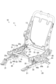
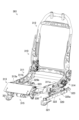
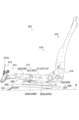
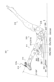
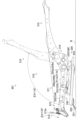
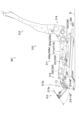
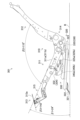
- FIG. 1 is a perspective view showing a vehicle seat device according to a first embodiment
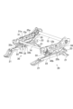
- FIG. FIG. 2 is a perspective view showing a state in which a back bracket and the like are removed from FIG. 1
- FIG. 3 is a plan view of the vehicle seat device in the state of FIG. 2
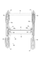
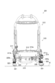
- FIG. 3 is a front view of the vehicle seat device in the state of FIG. 2
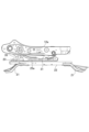
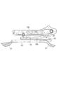
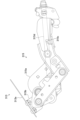
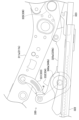
- FIG. 3 is a side view of the vehicle seat device in the state of FIG. 2 as viewed from one side
- FIG. 3 is a side view of the vehicle seat device in the state of FIG. 2 as viewed from the other side
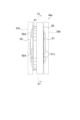
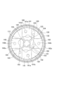
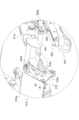
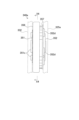
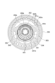
- 1 is a front view of a round unit according to a first embodiment
- FIG. FIG. 8 is a cross-sectional view taken along the line X1-X1 shown in FIG.
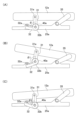
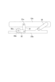
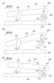
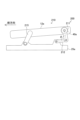
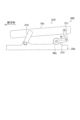
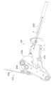
- FIG. 9(A) is an explanatory view schematically showing the tilting state of the link when the seat height is adjusted to a specified height
- FIG. FIG. 9C is an explanatory view schematically showing a state in which each link is tilted so that the angle of connection is increased
- FIG. 9C shows a state in which each link is tilted from the state of FIG. It is an explanatory view showing typically.
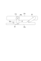
- FIG. 10 is an explanatory diagram showing a main part of a vehicle seat device according to a first modified example of the first embodiment
- FIG. 10 is an explanatory diagram showing a main part of a vehicle seat device according to a second modified example of the first embodiment
- FIG. 7 is an explanatory diagram showing a round unit employed in the vehicle seat device according to the second embodiment
- FIG. 13 is a cross-sectional view taken along the line X2-X2 shown in FIG. 12
- FIG. 13 is a cross-sectional view taken along the line X3-X3 shown in FIG. 12
- Fig. 15(A) is an explanatory diagram showing a main part of a vehicle seat device according to a third embodiment
- Fig. 15(A) shows the arrangement relationship of each link connected to a side bracket 12a and a riser 25a
- Fig. 15(B) indicates the positional relationship of each link connected to the side bracket 12b and the riser 25b.
- FIG. 15(A) shows the arrangement relationship of each link connected to a side bracket 12a and a riser 25a
- Fig. 15(B) indicates the positional relationship of each link connected to the side bracket 12b and the riser 25b.
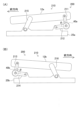
- FIG. 16A is an explanatory view showing the essential parts of a vehicle seat device according to a third embodiment
- FIG. 16(B) schematically shows a state in which each link is tilted so that the connection angle increases from the state in FIG. 16(A), and
- FIG. It schematically shows a state in which each link is tilted so that .
- FIG. 11 is an explanatory diagram showing a main part of a vehicle seat device according to a first modified example of the third embodiment
- FIG. 11 is an explanatory diagram showing a main part of a vehicle seat device according to a second modified example of the third embodiment
- It is a perspective view showing a vehicle seat device according to a fourth embodiment.
- FIG. 20 is a front view of the vehicle seat device of FIG. 19;
- FIG. 20 is a side view of the vehicle seat device of FIG. 19;
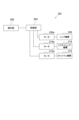
- FIG. 20 is a block diagram schematically showing the main electrical configuration of the vehicle seat device of FIG. 19; It is an explanatory view for explaining the 1st tilt angle, the 2nd tilt angle, and the 3rd tilt angle.
- FIG. 20 is an enlarged perspective view showing an enlarged vicinity of the ottoman of FIG. 19; It is an explanatory view explaining the storage state of the ottoman. It is an explanatory view explaining an unfolded state of an ottoman.
- FIG. 11 is an enlarged side view showing the vicinity of the link mechanism in a state where the first tilt angle is increased; It is a front view of the round unit which concerns on 4th Embodiment.
- FIG. 20 is a side view of the vehicle seat device of FIG. 19;
- FIG. 20 is a block diagram schematically showing the main electrical configuration of the vehicle seat device of FIG. 19; It is an explanatory view for explaining the 1st tilt angle, the 2nd tilt angle, and the 3r
- FIG. 29 is a cross-sectional view taken along the line X4-X4 shown in FIG. 28;
- FIG. 24 is an explanatory diagram illustrating a state in which the link mechanism operates to increase the first tilt angle from the state of FIG. 23;
- FIG. 24 is an explanatory diagram illustrating a state in which the reclining mechanism operates to increase the second tilt angle from the state of FIG. 23;
- FIG. 24 is an explanatory diagram illustrating a state in which the ottoman mechanism operates to increase the third tilt angle from the state of FIG. 23;
- FIG. 4 is an explanatory diagram for explaining a relaxed seat posture state;
- FIG. 11 is an explanatory diagram schematically showing a main part of a vehicle seat device according to a first modified example of the fourth embodiment;
- FIG. 11 is an explanatory diagram schematically showing a main part of a vehicle seat device according to a second modified example of the fourth embodiment;
- FIG. 11 is an explanatory diagram showing a round unit employed in a vehicle seat device according to a fifth embodiment;
- FIG. 21 is an explanatory diagram for comparing operation speeds when changing tilt angles between a seat posture changeable state and a seat posture change restricted state in the sixth embodiment;
- FIG. 11 is a side view showing a main part of a vehicle seat device according to a seventh embodiment;
- a vehicle seat device 10 is a device in which a vehicle seat 11 can be moved (slid) relative to a floor (vehicle body) in the front-rear direction, and the height with respect to the floor can be adjusted.
- the vehicle seat device 10 mainly includes a vehicle seat 11, a seat slide mechanism 20 for slidably supporting the vehicle seat 11 with respect to the floor surface, and a seat slide mechanism 20.
- a link mechanism (height mechanism) 30 is provided to support the vehicle seat 11 so that the height from the floor can be adjusted with respect to the mechanism 20 .
- the vehicle seat 11 includes a pair of left and right side brackets 12a and 12b functioning as seat brackets for supporting the seat cushion and a back bracket functioning as a seat bracket for supporting the seat back. 13, etc.
- a back bracket 13 is tiltable with respect to both side brackets 12a and 12b and is fixedly connected at a predetermined tilting angle, so that the tilting angle of the seatback with respect to the seat cushion can be adjusted.
- the two side brackets 12a and 12b are connected to each other via a rod 14 on the front side and connected to each other via a rod 15 on the rear side. 1 to 6, illustration of the seat cushion, seat back, etc. is omitted, and in FIGS. 5 and 6, illustration of a connecting shaft 41, which will be described later, is omitted.
- the seat slide mechanism 20 includes a pair of left and right lower rails 22 fixed to the floor surface via front and rear feet 21, an upper rail 23 assembled to the lower rails 22 so as to be slidable in the longitudinal direction, and a lock member.
- An operation lever is provided for switching the locked state of the lock member.
- Risers 25a and 25b are fixed to the upper surfaces of both upper rails 23 along the longitudinal direction thereof.
- the risers 25 a and 25 b function as base members (seat brackets) that connect the vehicle seat 11 and the seat slide mechanism 20 via each link of the link mechanism 30 .
- the lock member is arranged in a space surrounded by the lower rail 22 and the upper rail 23, and functions to lock (fix) the lower rail 22 and the upper rail 23 so that they cannot move relative to each other in the locked state.
- the lock member when the lock member is unlocked according to the operation of the operating lever, the lower rail 22 and the upper rail 23 are allowed to move relative to each other, and the vehicle seat 11 can be adjusted in the front-rear direction with respect to the floor surface. state. After the vehicle seat 11 has been slid to the desired position, the lock member is locked in response to the operation of the operating lever. The front-rear direction position with respect to the surface is fixed.
- the link mechanism 30 includes six links 31 to 36, two round units 40a and 40b, a connecting shaft 41, and a motor (not shown) that rotates the connecting shaft 41 in accordance with a predetermined operation on an operation unit (not shown). abbreviated).
- One end 31a of the link 31 is connected to the front inner surface of the side bracket 12a so as to be tiltable, and the other end 31b is connected to the round unit 40a.
- One end 32a of the link 32 is connected to the front inner surface of the riser 25a so as to be tiltable, and the other end 32b is connected to the round unit 40a.
- the link 31 and the link 32 are positioned inside the side bracket 12a and the riser 25a, and the other side end 32b of the link 32 is positioned inside the other side end 31b of the link 31. are placed in
- link 33 is tiltably connected to the front inner surface of the side bracket 12b, and the other end is connected to the round unit 40b.
- link 34 is tiltably connected to the front inner surface of the riser 25b, and the other end of the link 34 is connected to the round unit 40b.
- the link 33 and the link 34 are symmetrical with respect to the link 31 and the link 32, and are located inside the side bracket 12b and the riser 25b. 33 so as to be located inside the other side end.
- the links 31 and 33 may correspond to an example of a "first link”
- the links 32 and 34 may correspond to an example of a "second link”.
- One end of the link 35 is tiltably connected to the rear inner surface of the side bracket 12a, and the other end is tiltably connected to the rear inner surface of the riser 25a.
- One end of the link 36 is tiltably connected to the rear inner surface of the side bracket 12b, and the other end is tiltably connected to the rear inner surface of the riser 25b. .
- the round unit 40a changes the connection angle .theta. function to change the
- the round unit 40a includes two plates attached to the other side end 31b of the link 31 and the other side end 32b of the link 32. By controlling the relative rotation of these two plates, the link 31 and the link 32 are changed. Therefore, as the round units 40a and 40b according to the present embodiment, for example, a round unit that is generally used in a reclining mechanism of a vehicle seat device for controlling the tilt angle of the seatback with respect to the seat cushion may be adopted. can be done.
- the round unit 40a includes the above-described shaft 42, an external gear 51 and an internal gear that function as two relatively rotatable plates. 52, a U-shaped bush 53 functioning as a locking member, a pair of wedge-shaped cams 54, a spring 55, a plate cover 56, a shaft cover 57, and the like.
- the external gear 51 has external teeth 51a formed on its outer peripheral surface and a substantially cylindrical boss portion 51b formed in its center.
- the internal gear 52 is configured to include a cylindrical portion having internal teeth 52a formed on its inner peripheral surface and a side plate portion having a substantially cylindrical boss portion 52b formed in the center. Since the internal teeth 52a mesh eccentrically with the external teeth 51a, the internal teeth 52a are formed to have more teeth than the external teeth 51a.
- a resin bearing 52c is fitted inside the boss portion 52b of the internal gear 52, and the inner peripheral surface of the boss portion 52b and the outer peripheral surface of the boss portion 51b of the external gear 51 are formed by the resin bearing 52c.
- a U-shaped bush 53 and a pair of wedge-shaped cams 54 are arranged between them.
- the outer peripheral surface of the boss portion 51b of the external gear 51 corresponds to an example of "one first peripheral surface of two plates"
- the inner peripheral surface of the boss portion 52b of the internal gear 52 corresponds to "two plates.” It can correspond to an example of "the other second peripheral surface of the plate”.
- the shaft 42 is formed so as to be coaxially fitted to the inner peripheral surface of the boss portion 51b of the external gear 51 at the body portion 42a having serrations formed on the inner surface.
- the shaft 42 is provided with a U-shaped portion 42b so as to partially cover the outer peripheral surface of the boss portion 51b to which the body portion 42a is fitted.
- the U-shaped portion 42b is in contact with both end surfaces in the rotational direction of the U-shaped bushing 53 incorporated in the inner peripheral side of the boss portion 52b of the internal gear 52 at both end surfaces in the rotational direction.
- one wedge-shaped cam 54 When rotating in a rotation direction (hereinafter also referred to as a first rotation direction) for increasing the height of the vehicle seat 11 (hereinafter also simply referred to as seat height), one wedge-shaped cam 54 is pushed around, and the other wedge-shaped cam 54 is pushed around when it rotates in a rotation direction for lowering the seat height (hereinafter also referred to as a second rotation direction).
- the wedge-shaped cam 54 is formed in a wedge shape so that the thickness in the radial direction becomes thinner toward the tip.
- the wedge-shaped cam 54 is interposed between the outer peripheral surface of the boss portion 51b of the external gear 51 and the U-shaped bush 53 so that the end surface on the distal end side faces the end surface of the U-shaped portion 42b in the rotational direction. , and is pressed against both the outer peripheral surface of the boss portion 51b and the U-shaped bush 53 by being biased from the base end side by the spring 55. As shown in FIG.
- the internal gear 52 is eccentric with respect to the external gear 51, and some of the external teeth 51a mesh with the internal teeth 52a.
- the external gear 51 rotates relative to the internal gear 52 as described later, so that the meshing position between the external gear 51a and the internal gear 52a changes.
- 51 revolves around the gear shaft of the internal gear 52 .
- the pair of wedge-shaped cams 54 are interposed in a predetermined manner. The relative rotation between the external gear 51 and the internal gear 52 is restricted by intervening at a position.
- the plate cover 56 is attached to the internal gear 52 so as to suppress axial displacement of the external gear 51 with respect to the internal gear 52 .
- the shaft cover 57 is attached to the internal gear 52 so as to suppress axial displacement of the shaft 42 with respect to the internal gear 52 .
- the round unit 40a configured in this way is welded and fixed to the other end 32b of the link 32 using a plurality of projections 51c formed on the side surface of the external gear 51.
- the internal gear 52 is welded and fixed to the other side end 31b of the link 31 using a plurality of projections 52d formed on the side surface of the internal gear 52 .
- the other side end portion 31b of the link 31 and the other side end portion 32b of the link 32 are shown by dashed lines for convenience.
- the round unit 40b is welded and fixed to the other end of the link 34 using a plurality of protrusions 51c formed on the side surface of the external gear 51, and a plurality of protrusions formed on the side surface of the internal gear 52. It is welded and fixed to the other end of the link 33 using 52d.
- the shaft 42 of the round unit 40b and the shaft 42 of the round unit 40a are connected via a connecting shaft 41 (see FIGS. 3 and 4), and the connecting shaft 41 rotates according to the drive of the motor. and are configured to rotate synchronously.
- the round unit 40b changes the connection angle between the link 33 and the link 34 according to the rotational force input through the shaft 42 as the motor is driven, so that the side bracket 12b relative to the riser 25b is rotated. functions to change the height of
- the motor that rotates the connecting shaft 41 is attached to the link 32 and arranged to move along with the tilting of the link 32 .
- the link mechanism 30 configured in this way, when both the shafts 42 do not rotate because the operation portion is not operated, the pair of wedge-shaped cams 54 cause the external gear 51 and the internal gear 52 to rotate.
- the connection angle ⁇ between the links 31 and 32 and the connection angle between the links 33 and 34 do not change (hereinafter also referred to as a link connection angle maintained state).
- the seat height is maintained.
- the U-shaped portion 42b rotates the two wedge-shaped cams 54 in the rotation direction.
- One of the wedge-shaped cams 54 in the opposite direction is pushed around against the biasing force of the spring 55 to release the above-described pressing state of the one wedge-shaped cam 54, and the link is rotated in the first rotation direction.
- between the link 31 and the link 32 and the connection angle between the link 33 and the link 34 can be changed (hereinafter also referred to as a link connection angle variable state).
- the external gear 51 which rotates relative to the internal gear 52, rotates together with the shaft 42 in the first rotation direction.
- the link 33 and the link 34 tilt.
- the link connection angle variable state in which the connection angle between the two shafts 42 can be changed can be switched according to the presence or absence of an external force acting on both shafts 42 .
- the connection angle ⁇ increases, the links 31 and 32 tilt and the links 33 and 34 tilt (see symbol ⁇ 1 in FIG. 9B).
- the links 35 and 36 are also tilted, and the seat height is adjusted to be higher.
- the link mechanism 30 has two links (links 31 and 32 or links 33 and 34) connected to the front side and one link (links 35 and 36) to the rear side. Therefore, as can be seen from FIG. 9B, the front side of the seat cushion is higher. Therefore, the seating state can be changed so that the occupant sitting on the vehicle seat 11 can easily raise their thighs.
- the link 31 and the link 32 are tilted so as to decrease, and the link 33 and the link 34 are tilted (see symbol ⁇ 2 in FIG. 9(C)).
- the links 35 and 36 are also tilted, and the seat height is adjusted to be lower.
- the link mechanism 30 since the link mechanism 30 has the structure described above, the front side of the seat cushion is lower as can be seen from FIG. 9(C). Therefore, the seating state can be changed so that the occupant sitting on the vehicle seat 11 can easily recline his or her thighs.
- the front side of the seat cushion lower than the rear side as described above when getting off the vehicle, compared with the case where the front side of the seat cushion is higher than the rear side, it is possible to make it easier for the occupant to get off. can.
- the link mechanism 30 capable of adjusting the height of the side brackets 12a, 12b with respect to the risers 25a, 25b has one side end portion extending from the side brackets 12a, 12b.
- Links 31 and 33 tiltably connected to the risers 25a and 25b, links 32 and 34 tiltably connected to the risers 25a and 25b at one end, and the link angle between the links 31 and 32 are changed.
- the round units 40a and 40b include a shaft 42, locking members (a U-shaped bush 53, a pair of wedge-shaped cams 54, and a spring 55), the other side ends of the links 31 and 33, and the other side ends of the links 32 and 34. and two plates (an external gear 51 and an internal gear 52) attached to the shaft 42, and when no external force acts on the shaft 42, the locking member restricts the relative rotation of the two plates, and the external force The locking member is pushed around by the rotation of the shaft 42 corresponding to the rotation of the two plates, which are in a relatively rotatable state. changes.
- the height of the side brackets 12a and 12b relative to the risers 25a and 25b that is, when an external force such as an operating force for changing the seat height does not act on the shafts 42 of the round units 40a and 40b, the two plates are restricted, and the connection angle between the links 31, 33 and the links 32, 34 does not change, so the seat height is maintained.
- an external force such as the above-described operating force acts, the locking member is pushed around by the rotation of the shaft 42 corresponding to the external force, and the two plates, which are in a relatively rotatable state, rotate relative to each other.
- connection angle between the links 31, 33 and the links 32, 34 changes as a result, the seat height can be adjusted according to the change in the connection angle.
- the round unit 40a interposed between the link 31 and the link 32 and the round unit 40b interposed between the link 33 and the link 34 prevent the connection angle between the links 31, 33 and the links 32, 34 from changing.
- the connection angle maintaining state and the link connection angle variable state in which the connection angles between the links 31 and 33 and the links 32 and 34 can be changed can be switched according to the presence or absence of an external force acting on the shaft 42 .
- the internal gear 52 that is the other of the two plates has internal teeth 52a that can mesh with the external teeth 51a of the external gear 51 that is one of the two plates and have a different number of teeth from the external teeth 51a. It is formed. As a locking member, it intervenes between the outer peripheral surface of the boss portion 51b of the external gear 51 and the inner peripheral surface of the boss portion 52b of the internal gear 52 to eccentrically connect the external gear 51 and the internal gear 52. By doing so, some of the external teeth 51a and the internal teeth 52a are engaged with each other, and when no external force acts on the shaft 42, the outer peripheral surface of the boss portion 51b and the inner peripheral surface of the boss portion 52b are interposed at predetermined intervening positions.
- the link connection angle maintaining state is established. It is possible to realize the link mechanism 30 that can be switched to and from the link connection angle variable state with a simple mechanism according to the rotation of the shaft 42 .
- the round unit 40a is connected to both the one side end of the link 31 and the front side of the side bracket 12a, and the other side of the link 31
- the end portion and the other side end portion of the link 32 may be connected so that the connection angle can be changed.
- the round unit 40b is similarly connected to both the one side end of the link 33 and the front side of the side bracket 12b, and the other side end of the link 33 and the other side end of the link 34 form a connection angle. variably linked.
- the vehicle seat device is a bracket on which the vehicle seat is supported; a base member arranged below the bracket; a link mechanism capable of adjusting the height of the bracket with respect to the base member;
- a vehicle seat device comprising: The link mechanism is a first link; a second link whose one side end is tiltably connected to the base member and whose other side end is connected to the first link such that the connection angle can be changed; a round unit that is connected to one end of the first link and the bracket and changes the height of the bracket with respect to the base member by changing the connection angle between the first link and the second link; has The round unit is a shaft and a locking member; two plates attached to one side end of the first link and the bracket; with When no external force acts on the shaft, the locking member restricts the relative rotation of the two plates, and the rotation of the shaft in response to the external force pushes the locking member to rotate relative to each other.
- the vehicle seat device is characterized in that a connection angle between the first link and the second link
- the round unit 40b interposed therebetween switches between the link connection angle maintaining state and the link connection angle variable state in accordance with the presence or absence of an external force acting on the shaft 42, as in the vehicle seat device 10 according to the first embodiment. It is possible to achieve the effects described above.
- the round unit 40a is connected to both the one side end of the link 32 and the front side of the riser 25a, and the other side end of the link 31 is connected. and the other side end of the link 32 may be connected so that the connection angle can be changed.
- the round unit 40b is similarly connected to both the one side end of the link 34 and the front side of the riser 25b, and the other side end of the link 33 and the other side end of the link 34 change the connection angle. Connected as possible.
- the vehicle seat device is a bracket on which the vehicle seat is supported; a base member arranged below the bracket; a link mechanism capable of adjusting the height of the bracket with respect to the base member;
- a vehicle seat device comprising: The link mechanism is a first link having one side end tiltably connected to the bracket; a second link that is connected to the first link so that the connection angle can be changed; a round unit that is connected to one side end of the second link and the base member and that changes the height of the bracket with respect to the base member by changing the connection angle between the first link and the second link; , has The round unit is a shaft and a locking member; two plates attached to one side end of the second link and the base member; with When no external force acts on the shaft, the locking member restricts the relative rotation of the two plates, and the rotation of the shaft in response to the external force pushes the locking member to rotate relative to each other.
- the vehicle seat device is characterized in that a connection angle between the first link and the second link is changed by
- the round unit 40a interposed between the link 32 and the riser 25a or between the link 34 and the riser 25b can switch between the link connection angle maintaining state and the link connection angle variable state in accordance with the presence or absence of an external force acting on the shaft 42, as in the vehicle seat device 10 according to the first embodiment. It is possible to achieve the effects described above.
- the round unit 40a according to the first embodiment is not limited to being attached to the link 31 by the internal gear 52 and being attached to the link 32 by the external gear 51. and may be attached to the link 31 by the external gear 51 .
- the round unit 40b is not limited to being attached to the link 33 by the internal gear 52 and to the link 34 by the external gear 51, and is also attached to the link 34 by the internal gear 52 and the external gear. It may be attached to link 33 at 51 .
- a vehicle seat device 10 according to the present embodiment employs round units 100, 100 in place of the round units 40a, 40b of the vehicle seat device 10 according to the first embodiment described above, and also employs a vehicle seat. Springs (not shown) for urging the links 31 and 32 and the links 33 and 34 in the direction of pushing up 11 are newly employed.
- the round unit 100 includes a shaft 112 and an operation lever (not shown), a base plate 120 and a gear plate 130 functioning as two relatively rotatable plates, and relative rotation control.
- Four lock gears (two first lock gears 141 and two second lock gears 142) arranged in an internal space (cavity) formed by the base plate 120 and the gear plate 130 to perform the locking, a cam 150 functioning as a locking member , two spring members 160, a substantially disk-shaped lever plate 170, a cover bracket 180, and the like.
- the base plate 120 has a plurality of projections 121 formed on the outer surface constituting the outer surface of the round unit 100 and used for welding and fixing to the other side end 32b of the link 32, and on the inner surface constituting the cavity. , four guide projections 122, 123, 122, 123 for guiding the respective lock gears 141, 142 in the radial direction.
- the gear plate 130 has a plurality of projections 131 formed on the outer surface forming the outer surface of the round unit 100 and used when fixing the link 31 to the other side end 31b by welding. Internal teeth 132 are formed along the entire circumference on the inner peripheral surface of the portion.
- External teeth 141a and 142a that can be meshed with the internal teeth 132 of the gear plate 130 are formed on the outer peripheral sides of both the first lock gear 141 and both the second lock gears 142, respectively. Further, projections 141b and 142b are formed on the lock gears 141 and 142, respectively, so as to protrude toward the gear plate.
- Both the first lock gears 141 are guided by a linear portion (guide portion) between a movable guide 143 guided by the guide protrusion 123 and the side peripheral portion of the guide protrusion 122, and are supported so as to be slidable only in the radial direction.
- Both the second lock gears 142 are guided by guide portions on the side circumferences of the guide projections 123 and 122 and supported so as to be slidable only in the radial direction.
- a plate-like cam 150 having a through hole 151 formed in the center is rotatably arranged.
- the cam 150 has a cam surface 152 formed on its outer peripheral surface that abuts on the rear end surfaces of the lock gears 141 and 142, and two engaging holes 153 with which one end of the spring member 160 engages on its side surface, protruding toward the gear plate.
- Two cylindrical projections 154 are formed.
- the cam 150 is strongly biased in the lock rotation direction (clockwise in FIGS. 13 and 14) by engaging with one ends of the two spring members 160 respectively.
- the cam surface 152 of the cam 150 comes into contact with the rear end surfaces of the lock gears 141 and 142, so that the lock gears 141 and 142 are radially outwardly moved by the urging force of the spring members 160 in the lock rotation direction. It will force you strongly.
- the other ends of both spring members 160 are engaged with through-holes of the movable guide 143, respectively.
- the shaft end of the shaft 112 is inserted into the through hole 151 of the cam 150, and by rotating the shaft 112, the cam 150 is rotated in the unlocking direction (Fig. 13 and It can be rotated counterclockwise in FIG. 14).
- the lever plate 170 is provided with through holes 171 that are fitted to the two projections 154 of the cam 150, and two cam holes 172 and two cam holes 173, respectively.
- the through holes 171 and the protrusions 154 are fitted to each other, the protrusions 141b are inserted through the cam holes 172, and the protrusions 142b are inserted through the cam holes 173, respectively. and each lock gear 141 , 142 .
- the lock gears 141 and 142, the movable guide 143, the cam 150, and the like are arranged in the cavity and the side peripheral portions of the base plate 120 and the gear plate 130 are integrally assembled with the cover bracket 180 by ring caulking to integrate them. be done.
- the base plate 120 and the gear plate 130 are held so as to be relatively rotatable and their relative movement in the axial direction is suppressed.
- One of the round units 100 configured in this manner has a base plate 120 welded to the other end 32b of the link 32 using projections 121 on its outer surface, and a gear plate 130 attached to each projection on its outer surface. 131 is used to weld and fix to the other end 31b of the link 31, and the operating lever is attached to the shaft 112 inserted into the through hole 151 of the cam 150, thereby controlling the connection angle ⁇ between the link 31 and the link 32. function as possible.
- the base plate 120 is welded to the other end of the link 34 using projections 121 on its outer surface, and the gear plate 130 is fixed using projections 131 on its outer surface. is welded to the other end of the link 33, and the shaft 112 is connected to the shaft 112 of one round unit 100 via the connecting shaft 41, so that the connection angle between the link 33 and the link 34 can be controlled. function.
- the outer teeth 141a and 142a of the respective lock gears 141 and 142 are aligned with the gear plate 130 when the shaft 112 does not rotate because the operation lever is not operated.
- the link angle ⁇ between the links 31 and 32 and the link angle ⁇ between the links 33 and 34 are not changed, and the link angle between the links 31 and 32 is maintained.
- the link connection angle variable state in which ⁇ and the connection angle between the link 33 and the link 34 can be changed can be switched according to the presence or absence of an external force acting on the shaft 112 .
- one round unit 100 is positioned between the one side end 31a of the link 31 and the front side of the side bracket 12a, as in the first modification of the first embodiment.
- the other side end portion 31b of the link 31 and the other side end portion 32b of the link 32 may be connected so that the connection angle ⁇ can be changed.
- the other round unit 100 is similarly connected to both the one side end of the link 33 and the front side of the side bracket 12b, and the other side end of the link 33 and the other side end of the link 34 are connected. It is connected so that the angle can be changed.
- one round unit 100 is provided on both the one side end 32a of the link 32 and the front side of the riser 25a, as in the second modification of the first embodiment. , and the other end 31b of the link 31 and the other end 32b of the link 32 may be connected so that the connection angle ⁇ can be changed.
- the other round unit 100 is similarly connected to both one side end of the link 34 and the front side of the riser 25b, and the other side end of the link 33 and the other side end of the link 34 are connected at a connection angle of are connected so that ⁇ can be changed.
- one round unit 100 according to the second embodiment is not limited to being attached to the link 31 by the gear plate 130 and attached to the link 32 by the base plate 120, and is attached to the link 32 by the gear plate 130. and may be attached to link 31 at base plate 120 .
- the other round unit 100 is not limited to being attached to the link 33 by the gear plate 130 and attached to the link 34 by the base plate 120, but is also attached to the link 34 by the gear plate 130 and is attached to the base plate 120. It is attached to the link 33 at .
- the third embodiment is mainly different from the first embodiment and the modified examples in that the first link and the second link are arranged on the rear side of the vehicle seat. Therefore, the same reference numerals are given to substantially the same components as those of the first embodiment and each modified example, and the description thereof will be omitted.
- the link mechanism 30 of the vehicle seat device 10 serves as a first link when the direction in which the passenger seated on the vehicle seat 11 faces is the front direction.
- the links 31 and 33 and the links 32 and 34 which are the second links are arranged in the front direction with respect to the links 35 and 36 .
- the links 35 and 36 may correspond to an example of a "third link”.
- the front side of the vehicle seat 11 largely fluctuates in the vertical direction with respect to the rear side of the vehicle seat 11 . Therefore, as described above, the occupant sitting on the vehicle seat 11 can easily switch between a sitting state in which the thighs are likely to stand up and a sitting state in which the occupant is likely to lay down the thighs.
- the vehicle seat device 200 employs a link mechanism 210 instead of the link mechanism 30 in the vehicle seat device 10 according to the first embodiment. be done.
- the link mechanism 210 has a link 211 corresponding to the link 31 and a link 212 corresponding to the link 32 connected via a round unit 40a.
- the corresponding link 213 and the link 214 corresponding to the link 34 are connected via the round unit 40b.
- the links 211 and 212 are arranged on the rear side of the vehicle seat 11, and the link 215 corresponding to the link 35 is connected to the links 211 and 212. It is positioned forward.
- the links 213 and 214 are arranged on the rear side of the vehicle seat 11, and the link 216 corresponding to the link 36 is located between the links 213 and 214. positioned anteriorly with respect to
- the links 211 and 213 are examples of the "first link”
- the links 212 and 214 are examples of the "second link”
- the links 215 and 216 are examples of the "third link”.
- the link 211 and the link 212 are tilted so as to decrease, and the link 213 and the link 214 are tilted (see symbol ⁇ 2 in FIG. 16C). In response to such tilting, the links 215 and 216 are also tilted, and the seat height is adjusted to be lower.
- the space between the rear side of the vehicle seat 11 and the floor becomes large.
- the feet of another occupant can be easily put in, and the convenience of the vehicle seat 11 can be enhanced.
- the round unit 40a is connected to both the one side end of the link 211 and the rear side of the side bracket 12a, and the other side end of the link 211 is connected to the side bracket 12a. and the other side end of the link 212 may be connected so that the connection angle can be changed.
- the round unit 40b is similarly connected to both one side end of the link 213 and the rear side of the side bracket 12b, and the other side end of the link 213 and the other side end of the link 214 are connected at a connection angle of are variably linked.
- the round unit 40a interposed between the link 211 and the side bracket 12a and the connection between the link 213 and the side bracket 12b switches between the link connection angle maintaining state and the link connection angle variable state in accordance with the presence or absence of an external force acting on the shaft 42, as in the vehicle seat device 200 according to the third embodiment. It is possible to achieve the effects described above.
- the round unit 40a is connected to both the one side end of the link 212 and the rear side of the riser 25a, and the other side of the link 211
- the end portion and the other side end portion of the link 212 may be connected so that the connection angle can be changed.
- the round unit 40b is similarly connected to both the one side end of the link 214 and the rear side of the riser 25b, and the other side end of the link 213 and the other side end of the link 214 form a connection angle. variably linked.
- the round unit 40a interposed between the link 212 and the riser 25a and between the link 214 and the riser 25b can switch between the link connection angle maintaining state and the link connection angle variable state in accordance with the presence or absence of an external force acting on the shaft 42, as in the vehicle seat device 200 according to the third embodiment. It is possible to achieve the effects described above.
- the posture of the vehicle seat in which the passenger is seated can be changed to a relaxed posture (hereafter referred to as the “relaxed seat posture”).
- the tilting angle of the seat cushion with respect to the floor (hereinafter also referred to as the first tilting angle) is adjusted to be large by increasing the height of the front side of the seat cushion in the vehicle seat from the floor.
- the tilting angle of the seatback with respect to the seat cushion (hereinafter also referred to as the second tilting angle) to be large.
- the second tilt angle can be easily adjusted by using a conventional reclining mechanism.
- the vehicle seat 310 can be relatively moved (slid) in the front-rear direction with respect to the floor surface B of the vehicle. It is an electric power seat device that can automatically change the posture of 310 (seat posture) according to the operation of the passenger.
- the vehicle seat device 301 mainly includes a vehicle seat 310, a seat slide mechanism 320 for slidably supporting the vehicle seat 310 with respect to the floor surface B, and a seat slide mechanism 320.
- a link mechanism (height mechanism) 330 that supports the vehicle seat 310 so that the height from the floor surface B can be adjusted with respect to the slide mechanism 320, and an operation that is operated when changing the seat attitude of the vehicle seat 310.
- a control unit 303 that performs control according to an operation on the operation unit 302 .
- the vehicle seat 310 includes a seat cushion 311 installed slidably on the floor surface B, a seat back 312 attached to the rear side of the seat cushion 311 so as to be tiltable, and a seat cushion 311 facing the front side of the seat cushion 311. and an ottoman 313 that is tiltably attached to the ottoman. Further, the vehicle seat 310 has a reclining mechanism 314 capable of adjusting a second tilting angle ⁇ 2 (see FIG. 23), which is the tilting angle of the seat back 312 with respect to the seat cushion 311, and the tilting angle of the ottoman 313 with respect to the seat cushion 311. and an ottoman mechanism 315 capable of adjusting the third tilting angle ⁇ 3 (see FIG. 23).
- a pair of left and right side brackets 311a, 311b and the like that constitute the frame portion of the seat cushion 311 are illustrated for convenience, and the skin portion and the like are omitted.
- the seat back 312 and the ottoman 313 are shown with their frame portions and the like removed, and the skin portions and the like are omitted.
- FIG. 21 and the like for convenience, the shape of the frame and the like are simplified with respect to FIGS. 19 and 20 .
- the reclining mechanism 314 can correspond to an example of a "second tilting angle adjusting mechanism”
- the ottoman mechanism 315 can correspond to an example of a "third tilting angle adjusting mechanism”.
- the reclining mechanism 314 is a well-known mechanism for achieving electric reclining, and utilizes the rotational force of a motor 314a driven and controlled by the control unit 303 to adjust the tilt angle ( It functions to adjust the second tilt angle ⁇ 2).
- the reclining mechanism 314 is configured so that the second tilt angle ⁇ 2 varies within the range of 90° or more and 170° or less, but is not limited to this and can It may be configured to change.
- the ottoman mechanism 315 has a stored state (see FIG. 25) in which the ottoman 313 is stored under the seat cushion 311 and a deployed state (see FIG. 26) in which the ottoman 313 is deployed forward. It is a known mechanism for switchably moving.
- the ottoman mechanism 315 uses the rotational force of a motor 315a driven and controlled by the control unit 303 to tilt the ottoman 313 with respect to the seat cushion 311, more specifically, the ottoman frame 313a constituting the skeleton of the ottoman 313. It functions to adjust the tilt angle (third tilt angle ⁇ 3).
- the ottoman mechanism 315 includes a support portion 315b for supporting the ottoman frame 313a, a fixed portion 315c fixed to the side brackets 311a and 311b, a screw 315d rotated by the motor 315a, and fixed according to the rotation of the screw 315d. and an ottoman link portion 315e for moving the support portion 315b with reference to the portion 315c.
- the direction of movement of the rotating screw 315d is indicated by an arrow F.
- the ottoman mechanism 315 is configured so that the third tilt angle ⁇ 3 varies within the range of 90° or more and 150° or less, but the present invention is not limited to this, and a wider or narrower range is possible. may be configured to change at
- the seat slide mechanism 320 includes a pair of left and right lower rails 322 fixed to the floor surface B via front and rear feet 321 and the like, upper rails 323 assembled to the lower rails 322 so as to be slidable in the longitudinal direction thereof, and locking members.
- an operation lever (not shown) for switching the locked state of the lock member is provided. Note that in FIG. 19 and the like, illustration of the rear portion of the front and rear foot 321 is omitted for the sake of convenience.
- Risers 325a and 325b are fixed to the upper surfaces of both upper rails 323 along the longitudinal direction thereof. Risers 325 a and 325 b function as base members (seat brackets) that connect vehicle seat 310 and seat slide mechanism 320 via link mechanism 330 .
- the lock member is arranged in a space surrounded by the lower rail 322 and the upper rail 323, and functions to lock (fix) the lower rail 322 and the upper rail 323 so that they cannot move relative to each other in the locked state.
- the lock member when the lock member is unlocked according to the operation of the operation lever, the lower rail 322 and the upper rail 323 are allowed to move relative to each other, and the vehicle seat 310 is adjusted in the longitudinal direction with respect to the floor surface B. becomes possible. After the vehicle seat 310 is slid to the desired position, the lock member is locked in response to the operation of the operation lever, so that the lower rails 322 and the upper rails 323 become immovable relative to each other. The position in the front-rear direction with respect to the plane B is fixed.
- the link mechanism 330 shown in FIG. 27 functions as a height adjustment mechanism that can greatly adjust the height of the seat cushion 311 from the floor surface B, particularly the height of the front side, and tilts the seat cushion 311 with respect to the floor surface B. It functions as a first tilting angle adjusting mechanism capable of adjusting a first tilting angle ⁇ 1 (see FIG. 23).
- the link mechanism 330 includes six links 331 to 336, two round units 340a and 340b, a connecting shaft 341, and a motor 330a that rotates the connecting shaft 341 by being driven and controlled by the control unit 303.
- each tilt angle ⁇ 1 to ⁇ 3 is set with reference to a predetermined plane portion of each corresponding main frame.
- the first tilt angle ⁇ 1 is 4° and the second tilt angle
- the seat attitude state is illustrated in which ⁇ 2 is 110° and the third tilt angle ⁇ 3 is 98°.
- FIG. 27 shows an enlarged state in which the first tilt angle ⁇ 1 is larger than that in the predetermined basic state (see FIGS. 21 and 23).
- the link 331 and the link 332 are connected so that the connection angle ⁇ (see FIG. 27) can be changed. , and functions to change the height of the front side of the seat cushion 311 by changing the connection angle ⁇ .
- one side end of the link 331 (lower left end in FIG. 27) and one side end of the link 332 (upper left end in FIG. 27) are connected so as to be relatively tiltable.
- the other end of link 331 (upper left end in FIG. 27) is connected to the front side of side bracket 311a so as to be tiltable, and the other end of link 332 (lower right end in FIG. 27) is connected to the front side of side bracket 311a. It is assembled and fixed to the round unit 340a which is assembled to the riser 325a.
- the links 333 and 334 are connected so that the connection angle can be changed. It is provided on the floor surface B side, and functions to change the height of the front side of the seat cushion 311 by changing the connection angle. Specifically, one side end of the link 333 and one side end of the link 334 are connected so as to be relatively tiltable, and the other side end of the link 333 is connected so as to be tiltable with respect to the front side of the side bracket 311b. , and the other end of the link 334 is assembled and fixed to the round unit 340b assembled to the riser 325b.
- the links 331 and 333 may correspond to an example of a "first link”
- the links 332 and 334 may correspond to an example of a "second link”.
- the link 335 has one end tiltably connected to the rear side of the side bracket 311a and the other end tiltably connected to the rear side of the riser 325a.
- the link 336 has one end tiltably connected to the rear side of the side bracket 311b and the other end tiltably connected to the rear side of the riser 325b.
- the round unit 340a changes the connection angle ⁇ between the link 331 and the link 332 according to the rotational force input through the shaft 342 as the motor 330a controlled by the control unit 303 is driven. It functions to change the height of the side bracket 311a relative to 325a (in particular, the height of the front side).
- the round unit 340a has two plates attached to the other end of the link 332 and the riser 325a. By controlling the relative rotation of these two plates, the connection angle ⁇ change. For this reason, as the round units 340a and 340b according to the present embodiment, for example, a round unit that is generally employed in a reclining mechanism of a vehicle seat device for controlling the tilting angle of the seatback with respect to the seat cushion may be employed. can be done.
- the round unit 340a includes the shaft 342 described above, an external gear 351 and an internal gear 352 that function as two relatively rotatable plates. , a U-shaped bush 353 functioning as a locking member, a pair of wedge-shaped cams 354, a spring 355, a plate cover 356, a shaft cover 357, and the like.
- the shaft 342 corresponds to an example of an "input shaft”
- the external gear 351 and the internal gear 352 are "first rotating body and second rotating body” that rotate relative to each other according to the rotation of the "input shaft”. can correspond to an example of
- the external gear 351 has external teeth 351a formed on its outer peripheral surface and a substantially cylindrical boss portion 351b formed in its center.
- the internal gear 352 is configured to include a cylindrical portion having internal teeth 352a formed on the inner peripheral surface and a side plate portion having a substantially cylindrical boss portion 352b formed in the center. Since the internal teeth 352a mesh eccentrically with the external teeth 351a, the internal teeth 352a are formed to have more teeth than the external teeth 351a.
- a resin bearing 352c is fitted inside the boss portion 352b of the internal gear 352, and the inner peripheral surface of the boss portion 352b and the outer peripheral surface of the boss portion 351b of the external gear 351 are formed by the resin bearing 352c.
- a U-shaped bush 353 and a pair of wedge-shaped cams 354 are arranged between them.
- the outer peripheral surface of the boss portion 351b of the external gear 351 corresponds to an example of "one first peripheral surface of two plates", and the inner peripheral surface of the boss portion 352b of the internal gear 352 corresponds to "two plates.” It can correspond to an example of "the other second peripheral surface of the plate”.
- the shaft 342 is formed so as to be coaxially fitted to the inner peripheral surface of the boss portion 351b of the external gear 351 at the body portion 342a having serrations formed on the inner surface.
- the shaft 342 is provided with a U-shaped portion 342b so as to partially cover the outer peripheral surface of the boss portion 351b to which the body portion 342a is fitted.
- This U-shaped portion 342b abuts on both rotational direction end faces of a U-shaped bushing 353 incorporated in the inner peripheral side of the boss portion 352b of the internal gear 352.
- One wedge-shaped cam 354 is pushed around when rotating in a rotation direction (hereinafter also referred to as a first rotation direction) for increasing the height of the vehicle seat 310 (hereinafter simply referred to as seat height), It is formed to push around the other wedge-shaped cam 354 when it rotates in a rotation direction for lowering the seat height (hereinafter also referred to as a second rotation direction).
- the wedge-shaped cam 354 is formed in a wedge shape so that the thickness in the radial direction becomes thinner toward the tip end.
- the wedge-shaped cam 354 is interposed between the outer peripheral surface of the boss portion 351b of the external gear 351 and the U-shaped bush 353 so as to face the end surface of the U-shaped portion 342b in the rotational direction at the end surface on the tip side, It is arranged so as to be pressed against both the outer peripheral surface of the boss portion 351b and the U-shaped bushing 353 by being biased from the base end side by the spring 355 .
- the internal gear 352 is eccentric with respect to the external gear 351, and some of the external teeth 351a mesh with the internal teeth 352a.
- the external gear 351 rotates relative to the internal gear 352 as will be described later, thereby changing the meshing position between the external gear 351a and the internal gear 352a. revolves around the gear shaft of the internal gear 352 .
- the pair of wedge-shaped cams 354 are interposed in a predetermined manner. The relative rotation between the external gear 351 and the internal gear 352 is restricted by intervening at the position.
- the plate cover 356 is attached to the internal gear 352 so as to suppress axial displacement of the external gear 351 with respect to the internal gear 352 .
- the shaft cover 357 is attached to the internal gear 352 so as to suppress axial displacement of the shaft 342 with respect to the internal gear 352 .
- the round unit 340a configured in this way is welded and fixed to the other side end of the link 332 using a plurality of projections 351c formed on the side surface of the external gear 351.
- the internal gear 352 is welded and fixed to the front side of the riser 325a using a plurality of protrusions 352d formed on the side surface thereof.
- the link 332 and the riser 325a are simply illustrated with broken lines for convenience.
- the round unit 340b is welded and fixed to the other end of the link 334 using a plurality of protrusions 351c formed on the side surface of the external gear 351, and a plurality of protrusions formed on the side surface of the internal gear 352. 352d is used to weld and fix to the front side of riser 325b.
- the shaft 342 of the round unit 340b and the shaft 342 of the round unit 340a are connected via a connecting shaft 341 (see FIG. 24), and are synchronized by rotating the connecting shaft 341 in accordance with the drive of the motor 330a.
- the round unit 340b changes the connection angle between the link 333 and the link 334 in accordance with the rotational force input through the shaft 342 when the motor 330a is driven, thereby adjusting the side bracket 311b relative to the riser 325b. function to vary the height of the (especially the anterior side).
- connection angle ⁇ between the links 331 and 332 and the connection angle between the links 333 and 334 do not change (hereinafter also referred to as a link connection angle maintained state).
- this link connection angle maintained state the seat height and the first tilt angle ⁇ 1 are maintained.
- the external gear 351 which rotates relative to the internal gear 352, rotates in the first rotation direction together with the shaft 342, thereby tilting the links 331 and 332 so that the connection angle ⁇ increases.
- Link 333 and link 334 tilt. This increases the seat height and increases the first tilt angle ⁇ 1.
- the link mechanism 330 is configured such that two links (links 331 and 332 or links 333 and 334) are arranged on the front side and one link (links 335 and 336) is arranged on the rear side. Therefore, the height adjustment range on the front side of the seat cushion 311 is larger than that on the rear side of the seat cushion 311 . That is, the front side of the seat cushion 311 becomes higher by increasing the first tilt angle ⁇ 1.
- Link 333 and link 334 tilt.
- the seat height becomes lower and the first tilt angle ⁇ 1 becomes smaller.
- the link mechanism 330 is configured so that the first tilt angle ⁇ 1 varies within a range of ⁇ 4° or more and 42° or less, but the invention is not limited to this, and can be set to a wider or narrower range. may be configured to vary with
- the link connection angle variable state in which the connection angle between the two shafts 342 can be changed can be switched according to the presence or absence of an external force acting on both shafts 342 .
- the round units 340a and 340b are configured such that the internal gear 352 and the external gear 351 rotate relative to each other according to the rotation of the shaft 342, the relative rotation angle between the internal gear 352 and the external gear 351 can be easily adjusted.
- the link 332 (334) to which the external gear 351 is connected can be largely tilted with respect to the riser 325a (floor surface side) to which the internal gear 352 is connected.
- the variable range of the connection angle ⁇ between 332 (334) and the link 331 (333), which is connected to the link 332 (334) so that the connection angle ⁇ can be changed can be relatively tilted using a sector gear or the like. It can be made larger than the variable range of the connection angle of the two links to be connected (for example, the maximum value is 7°).
- the operation unit 302 is operated when changing the seat posture of the vehicle seat 310 by the seat cushion 311 , the seat back 312 and the ottoman 313 , and the vehicle seat 310 can be operated by an occupant seated on the vehicle seat 310 . are placed on the sides of The operation unit 302 drives and controls a switch and a motor 314a that are operated when changing the first tilting angle ⁇ 1 (the tilting angle of the seat cushion 311 with respect to the floor surface B) by controlling the driving of the motor 330a to perform the second tilting.
- ⁇ 1 the tilting angle of the seat cushion 311 with respect to the floor surface B
- a third tilt angle ⁇ 3 tilt angle of the ottoman 313 with respect to the seat cushion 311) is changed by driving and controlling the switch and motor 315a operated when changing the angle ⁇ 2 (tilt angle of the seat back 312 with respect to the seat cushion 311). It is equipped with a switch that is operated when the seat is being operated, a switch for registering the current seat posture, etc.
- the control unit 303 drives and controls the motors 314a, 315a, and 330a according to the operation of the operation unit 302, thereby controlling the link mechanism 330, the reclining mechanism 314, and the ottoman mechanism 315.
- Seat posture change processing is performed to change the seat posture of .
- the control unit 303 is mainly composed of a microcomputer, and has a CPU, a memory, a system bus, an input/output interface, and the like.
- Information on the seat posture (registered seat posture information including information on tilt angles ⁇ 1 to ⁇ 3 for changing to the registered seat posture) and the like are stored. As a result, it is possible to easily change the seat posture according to the operation of the operation unit 302, and to greatly adjust the tilt angle (first tilt angle ⁇ 1) of the seat cushion 311 with respect to the floor surface B when the seat posture is changed. can.
- the link mechanism 330 is operated to increase the first tilt angle ⁇ 1 by the motor 330a driven and controlled by the seat attitude change processing performed by the control unit 303 .
- the seat posture of the vehicle seat 310 is changed such that the height of the front side of the seat cushion 311 is increased.
- FIG. 30 illustrates a state in which the first tilt angle ⁇ 1 is 24°.
- the ottoman link portion 315e of the ottoman mechanism 315 is partially omitted from illustration for the sake of convenience.
- the reclining mechanism 314 is operated by the motor 314a to increase the second tilting angle ⁇ 2.
- the seat posture of the vehicle seat 310 is changed such that the seat back 312 is largely tilted rearward with respect to the seat cushion 311 .
- the solid line shows the state where the second tilt angle ⁇ 2 is 170°
- the two-dot chain line shows the state where the second tilt angle ⁇ 2 corresponding to FIG. 23 is 110°.
- the ottoman mechanism 315 operates so as to increase the third tilt angle ⁇ 3 by the motor 315a.
- the seat attitude of the vehicle seat 310 is changed so that the ottoman 313 is deployed forward.
- the solid line shows the state where the third tilt angle ⁇ 3 is 142°
- the two-dot chain line shows the state where the third tilt angle ⁇ 3 corresponding to FIG. 23 is 98°.
- the operation unit 302 is operated to change the seat posture to the registered seat posture.
- the link mechanism 330, the reclining mechanism 314, and the ottoman mechanism 315 are operated so that the tilt angle corresponding to the registered seat posture information is obtained by the seat posture change processing performed by the control unit 303, whereby the vehicle seat is changed.
- the posture of 310 is changed to the seat posture described above.
- the relaxation seat posture state is not limited to adopting each tilting angle shown in FIG. A tilting angle of 90° or more and 150° or less may be adopted as the second tilting angle ⁇ 2, and a tilting angle of 134° or more and 150° or less may be adopted as the third tilting angle ⁇ 3. If registered seat posture information such as tilting angles ⁇ 1 to ⁇ 3 for changing to the relaxed seat posture state is registered in the memory of the control unit 303, the relaxed seat posture can be changed from a predetermined basic state by a simple operation. Posture can be changed.
- control unit 303 when the control unit 303 receives a seat attitude change restriction instruction for restricting a change in the seat attitude from an external device (for example, an ECU controlling the overall control of the vehicle in which the vehicle seat device 301 is mounted), the control unit 303 , to maintain the seat posture regardless of the operation on the operation unit 302 .
- the control unit 303 receives a seat posture change restriction instruction from the ECU or the like, thereby preventing the seat posture from being changed due to an erroneous operation of the operation unit 302. - ⁇
- the link mechanism 330 which is a height adjustment mechanism capable of adjusting the height of the front side of the seat cushion 311 from the floor surface B
- the links 331 and 333 provided on the side of the floor surface B, the links 332 and 334 provided on the side of the floor surface B, and the connection angle ⁇ between the links 331 and 332 and the connection angle between the links 333 and 334 are changed to change the seat cushion.
- the link 331 and the link 332 are connected so that the connection angle ⁇ can be changed.
- the toothed gear 351 is connected to the link 332, and the internal gear 352 is connected to the front side of the riser 325a on the floor surface B side.
- the link 333 and the link 334 are connected so that the connection angle can be changed.
- the external gear 351 is connected to the link 334, and the internal gear 352 is connected to the front side of the riser 325b on the floor surface B side.
- the round units 340a and 340b are configured such that the external gear 351 and the internal gear 352 rotate relative to each other according to the rotation of the shaft 342, the relative rotation angle between the external gear 351 and the internal gear 352 can be easily increased. can do. Therefore, the links 332 and 334 to which the external gear 351 is connected can be largely tilted with respect to the risers 325a and 325b (floor surface B side) to which the internal gear 352 is connected.
- the variable range of the angle ⁇ and the connection angle between the link 334 and the link 333 can be increased.
- the vehicle seat device 301 by increasing the height of the front side of the seat cushion 311 from the floor surface B, it is possible to realize the vehicle seat device 301 in which the first tilting angle ⁇ 1 of the seat cushion 311 with respect to the floor surface B can be largely adjusted. can.
- the other end of the link 331 is connected to the front side of the side bracket 311a so that the other end of the link 332 can tilt.
- the section may be tiltably connected to the front side of the riser 325a.
- one side end of the link 333 provided on the seat cushion 311 side and one side end of the link 334 provided on the floor surface B side are connected by the round unit 340b such that the connection angle can be changed.
- the other side end of 333 is tiltably connected to the front side of side bracket 311b, and the other side end of link 334 is tiltably connected to the front side of riser 325b.
- the vehicle seat device is a seat cushion installed so as to be slidable in the front-rear direction with respect to the floor surface of the vehicle; a seat back assembled so as to be tiltable with respect to the rear side of the seat cushion; an ottoman attached to the front side of the seat cushion so as to be tiltable; a height adjustment mechanism capable of adjusting the height of the front side of the seat cushion from the floor;
- a vehicle seat device comprising: The height adjustment mechanism is a first link provided on the seat cushion side; a second link provided on the floor surface side; a round unit that changes the height of the front side of the seat cushion by changing the connection angle between the first link and the second link; has The round unit is An input shaft and a first rotating body and a second rotating body that rotate relative to each other according to the rotation of the input shaft, one of the first rotating body and the second rotating body being connected to the first link to form the
- the vehicle seat device is characterized in that the other of the first rotating body and the second rotating body is connected to the second
- the round unit 340a interposed between the link 331 and the link 332 and between the link 333 and the link 334 can increase the variable range of the connection angle ⁇ between the links 331 and 332 and the variable range of the connection angle between the links 333 and 334.
- the first tilting angle ⁇ 1 of the seat cushion 311 with respect to the floor surface B can be adjusted to a large extent.
- a round unit 340a is connected to both the other side end of the link 331 and the front side of the side bracket 311a so that the link One side end of the link 331 and one side end of the link 332 may be connected so that the connection angle ⁇ can be changed, and the other side end of the link 332 may be connected so as to be tiltable with respect to the front side of the riser 325a.
- the round unit 340b is connected to both the other side end of the link 333 and the front side of the side bracket 311b, and the connection angle between the one side end of the link 333 and the one side end of the link 334 can be changed.
- the other end of the link 334 is tiltably connected to the front side of the riser 325b.
- the vehicle seat device is a seat cushion installed so as to be slidable in the front-rear direction with respect to the floor surface of the vehicle; a seat back assembled so as to be tiltable with respect to the rear side of the seat cushion; an ottoman attached to the front side of the seat cushion so as to be tiltable; a height adjustment mechanism capable of adjusting the height of the front side of the seat cushion from the floor;
- a vehicle seat device comprising: The height adjustment mechanism is a first link provided on the seat cushion side; a second link provided on the floor surface side; a round unit that changes the height of the front side of the seat cushion by changing the connection angle between the first link and the second link; has The first link and the second link are connected so that the connection angle can be changed,
- the round unit is An input shaft and a first rotating body and a second rotating body that rotate relative to each other according to the rotation of the input shaft, one of the first rotating body and the second rotating body being connected to the first link to form the
- the vehicle seat device is characterized
- the round unit 340a interposed between the link 331 and the side bracket 311a and the connection between the link 333 and the side bracket 311b makes it possible to increase the variable range of the connection angle ⁇ between the links 331 and 332 and the variable range of the connection angle between the links 333 and 334. It is possible to realize a vehicle seat device in which the first tilting angle ⁇ 1 of the seat cushion 311 with respect to the floor surface B can be adjusted to a large extent by increasing the height from the base.
- the round unit 340a according to the fourth embodiment is not limited to connecting the external gear 351 to the link 332 and connecting the internal gear 352 to the front side of the riser 325a on the floor surface B side.
- the toothed gear 352 may be connected to the link 332 and the externally toothed gear 351 may be connected to the front side of the riser 325a on the floor surface B side.
- the round unit 340b is not limited to connecting the external gear 351 to the link 334 and connecting the internal gear 352 to the front side of the riser 325b on the floor surface B side.
- the external gear 351 may be connected to the front side of the riser 325b on the floor surface B side.
- a vehicle seat device according to a fifth embodiment of the present invention will be described with reference to the drawings.
- the fifth embodiment is different from the fourth embodiment and each modification mainly in that the structure of the round unit is changed. Therefore, the same reference numerals are assigned to substantially the same components as those of the fourth embodiment and each modified example, and description thereof will be omitted.
- the vehicle seat device 301 according to the present embodiment has the round units 100 and 340 described in the second embodiment instead of the round units 340a and 340b in the vehicle seat device 301 according to the fourth embodiment.
- 100 is employed, and springs (not shown) are newly employed to urge the links 331 and 332 and the links 333 and 334 in the direction of pushing up the vehicle seat 310 .
- the round units 100 and 100 in the present embodiment do not employ the motor 330a, and the connection angle ⁇ between the link 331 and the link 332 and the connection angle ⁇ between the link 333 and the link 334 are controlled by manual operation.
- the reclining mechanism 314 is configured to change the second tilting angle ⁇ 2 by using the rotational force of the motor 314a as in the fourth embodiment, but the motor 314a is employed. Alternatively, the second tilt angle ⁇ 2 may be changed in accordance with manual operation. Further, in the fourth embodiment, the reclining mechanism 314 may be configured to change the second tilting angle ⁇ 2 according to manual operation without using the motor 314a. Similarly, in the present embodiment, the ottoman mechanism 315 is configured to change the third tilting angle ⁇ 3 using the rotational force of the motor 315a as in the fourth embodiment, but the motor 315a is employed. Alternatively, the third tilt angle ⁇ 3 may be changed in accordance with the manual operation. Further, in the fourth embodiment, the ottoman mechanism 315 may be configured to change the third tilting angle ⁇ 3 according to manual operation without employing the motor 315a.
- one round unit 100 has a base plate 120 welded to the other end of a link 332 using projections 121 on its outer surface, and a gear plate 130 attached to each projection on its outer surface.
- 131 is used to weld and fix to the front side of the riser 325a, and the operation lever is attached to the shaft 112 inserted into the through hole 151 of the cam 150, so that the connection angle ⁇ between the link 331 and the link 332 can be controlled.
- the base plate 120 is welded to the other end of the link 334 using projections 121 on its outer surface, and the gear plate 130 is fixed using projections 131 on its outer surface.
- the shaft 112 corresponds to an example of the "input shaft”
- the base plate 120 and the gear plate 130 are examples of the "first rotating body and second rotating body” that rotate relative to each other according to the rotation of the "input shaft”. can be equivalent.
- the outer teeth 141a and 142a of the respective lock gears 141 and 142 are aligned with the gear plate 130 when the shaft 112 does not rotate because the operation lever is not operated.
- the link connection angle variable state in which the connection angle ⁇ between the links 331 and 332 and the connection angle between the links 333 and 334 can be changed can be switched according to the presence or absence of an external force acting on the shaft 112 .
- the round unit 100 is configured such that the base plate 120 and the gear plate 130 rotate relative to each other according to the rotation of the shaft 112, the relative rotation angle between the base plate 120 and the gear plate 130 can be easily increased.
- the link 332 (334) to which the base plate 120 is connected can be largely tilted with respect to the riser 325a (floor surface side) to which the gear plate 130 is connected.
- the variable range of the connection angle ⁇ between the link 331 (333) that is connected to the link 331 (333) so that the connection angle ⁇ can be changed is changed by using a sector gear or the like to change the connection angle of the two links that are connected so that the connection angle ⁇ can be changed. It can be larger than the range.
- one side end of the link 331 provided on the seat cushion 311 side and a link 331 provided on the floor surface B side are provided in the same manner as in the first modification of the fourth embodiment.
- One side end of the link 332 is connected by one round unit 100 so that the connection angle ⁇ can be changed, and the other side end of the link 331 is connected to the front side of the side bracket 311a so as to be tiltable.
- the other end of 332 may be tiltably connected to the front side of riser 325a.
- one side end of the link 333 provided on the seat cushion 311 side and one side end of the link 334 provided on the floor surface B side are connected by the other round unit 100 so that the connection angle can be changed.
- the other side end of the link 333 is tiltably connected to the front side of the side bracket 311b
- the other side end of the link 334 is tiltably connected to the front side of the riser 325b.
- one round unit 100 can be attached to both the other side end of the link 331 and the front side of the side bracket 311a in the same manner as the second modification of the fourth embodiment.
- one side end of the link 331 and one side end of the link 332 are connected so that the connection angle ⁇ can be changed, and the other side end of the link 332 is connected so as to be tiltable with respect to the front side of the riser 325a.
- the other round unit 100 is connected to both the other side end of the link 333 and the front side of the side bracket 311b, and the connection angle between the one side end of the link 333 and the one side end of the link 334 is changed.
- the other end of the link 334 is tiltably connected to the front side of the riser 325b.
- the base plate 120 is connected to the link 332, and the gear plate 130 is not limited to being connected to the front side of the riser 325a on the floor surface B side. 130 may be connected to the link 332 so that the base plate 120 may be connected to the front side of the riser 325a on the floor surface B side.
- the other round unit 100 is not limited to the base plate 120 being connected to the link 334 and the gear plate 130 being connected to the front side of the riser 325b on the floor B side.
- the base plate 120 may be connected to the front side of the riser 325b on the floor surface B side.
- the operating speed for operating the link mechanism 330 capable of adjusting the first tilt angle ⁇ 1 is a predetermined limited speed that is lower than the normal speed when the seat attitude change is not restricted.
- the main difference from the fourth embodiment and each modified example is that the control is performed so that Therefore, the same reference numerals are assigned to substantially the same components as those of the fourth embodiment and each modified example, and description thereof will be omitted.
- the occupant when riding for a long time while resting in a service area or charging an electric vehicle, the occupant changes the posture of the vehicle seat in which they are seated into a relaxed posture (hereinafter, also referred to as a relaxed seat posture). may change to Therefore, by storing the state of the seat posture for driving and the state of the relaxing seat posture so as to be switchable and controllable, the seat posture can be easily changed according to the operation by the passenger.
- a relaxed seat posture hereinafter, also referred to as a relaxed seat posture
- the operation to change the seat position to the relaxed seat position is not limited to when the vehicle is stopped, but may be performed even during autonomous driving. Sometimes it is. On the other hand, even when the vehicle is stopped, there are cases in which the seat posture is not permitted to be changed according to the change operation by the occupant.
- the seat attitude change restriction state in which the movement for changing the seat position to a predetermined position is restricted for the occupant who performs the seat position change operation, and in a state where no failure or the like has occurred.
- the operating speed of the link mechanism 330 is controlled when the seat attitude change is restricted.
- the seat posture change performed by the control unit 303 is controlled.
- the operation speed for operating the link mechanism 330 capable of adjusting the first tilt angle ⁇ 1 is set to a predetermined limit speed that is lower than the normal speed when the seat attitude change is not restricted (when the seat attitude is changeable).
- the predetermined speed limit is set, for example, to be 1/2 of the normal speed when the seat attitude change is not restricted.
- the predetermined posture is a posture that changes the first tilt angle ⁇ 1 from the current seat posture, and the first tilt angle ⁇ 2 and the third tilt angle ⁇ 3 are changed regardless of whether the second tilt angle ⁇ 2 and the third tilt angle ⁇ 3 are changed. Not only the posture that changes the angle ⁇ 1 to increase, but also the posture that changes the first tilt angle ⁇ 1 to decrease are included.
- the operation speed for operating the reclining mechanism 314 capable of adjusting the second tilting angle ⁇ 2 and the ottoman mechanism 315 capable of adjusting the third tilting angle ⁇ 3 are operated.
- the operation speed to be operated is controlled so as not to be different from the operation speed (normal speed) when the seat attitude change is not restricted (when the seat attitude is changeable) even in the seat attitude change restricted state.
- the control unit 303 determines that the seat attitude change is restricted.
- the control unit 303 can correspond to an example of a “determining unit” that determines whether or not a seat attitude change restriction state is set to restrict an operation for changing the seat attitude to a predetermined attitude.
- the operation unit 302 when the driver, who is a passenger, operates the operation unit 302 to greatly change the first tilt angle ⁇ 1 (operation to change the seat posture to the predetermined posture) during driving.
- the operation speed of the link mechanism 330 for changing the first tilting angle ⁇ 1 is set to the above-described value because it is determined that the seat attitude change restriction instruction is given by the seat attitude change processing performed by the control unit 303 in response to this operation.
- the specified speed limit is reached.
- the seat attitude changes such that the front side of the seat cushion 311 is slowly lifted.
- the operating speed of the link mechanism 330 that changes the first tilt angle ⁇ 1 in the seat attitude change limited state is set to the above-described predetermined speed limit.
- the seat posture changes so that the driver's (occupant's) feet are away from the brake pedal and the accelerator pedal. It may cause trouble.
- the seat posture changes so that the sense of distance between the driver's (occupant's) feet and the brake and accelerator pedals changes. In addition, it may interfere with driving.
- the vehicle seat device 301 when an operation for changing the first tilting angle ⁇ 1 (seat posture changing operation for changing the seat posture to a predetermined posture) is performed, Since the vehicle is being driven, it is determined that the seat attitude change is limited, so that the operating speed for operating the link mechanism 330 becomes the predetermined speed limit, and the first tilt angle ⁇ 1 changes relatively slowly.
- the driver can not only recognize that the seat attitude is changing in accordance with the seat attitude change operation, but also the seat attitude change restriction state in which the operation for changing the seat attitude to a predetermined attitude is restricted.
- the seat posture does not change even if the operation is performed, there is no possibility of erroneously recognizing that there is a failure or the like.
- the first tilt angle ⁇ 1 changes relatively slowly, even if the driver makes an erroneous operation while driving, the driver can immediately notice the erroneous operation. Therefore, it is a seat posture change restricted state in which an operation for changing the seat posture to a predetermined posture is restricted for a passenger such as a driver who performs a seat posture change operation, and no failure or the like has occurred. can be easily recognized.
- the seat posture change processing performed by the control unit 303 is limited to receiving a seat posture change restriction instruction from the ECU and determining that the seat posture change is restricted when the vehicle speed exceeds a predetermined threshold value. Instead, it may be determined that the seat posture change is restricted by receiving a seat posture change restriction instruction from the ECU by satisfying a condition other than the vehicle speed.
- a predetermined automatic driving signal indicating that the vehicle is in a predetermined automatic driving mode (for example, automatic driving level 3 or higher) is received from the ECU or an external device.
- the seat position change restriction state may not be determined regardless of the vehicle speed or an instruction from the ECU.
- a high-level automatic driving mode for example, automatic driving level 3 or higher
- the operation speed for operating the link mechanism 230 is prevented from becoming the predetermined speed limit unnecessarily. can do.
- the seventh embodiment is mainly different from the sixth embodiment and the like in that the operating speed for operating the link mechanism 330 is changed according to the slide position of the seat cushion 311 . Therefore, the same reference numerals are assigned to substantially the same components as those of the sixth embodiment, etc., and the description thereof will be omitted.
- the seat slide mechanism 320 moves the seat cushion 311 to the predetermined posture.
- the operating speed for operating the link mechanism 330 is set at the above-described predetermined speed regardless of whether or not the seat attitude change restriction instruction is received (regardless of the determination result by the determination unit). is controlled to be the speed limit of
- the predetermined slide position is set to a range from the position where the seat cushion 311 is slid to the frontmost position to a position that is rearward by a predetermined distance (for example, 1/3 of the slidable range).
- a predetermined distance for example, 1/3 of the slidable range
- the vehicle seat device 301 is provided with detection means such as a sensor for detecting whether or not the seat cushion 311 is positioned forward of the predetermined slide position, and the detection result by the detection means is controlled. It is configured to be output to the unit 303 . Note that when the seat slide mechanism 320 positions the seat cushion 311 behind the predetermined slide position, the operation speed for operating the link mechanism 330 is set to The speed is controlled to a predetermined limit speed, and is controlled to a normal speed when no seat posture change limit instruction is received.
- the front side of the seat cushion 311 is raised at the first tilt angle.
- ⁇ 1 changes, there is a possibility that the driver's (passenger's) foot touches the steering wheel H even when the vehicle is not determined to be in the seat posture change restricted state.
- the surfaces of the seat cushion 311, the seat back 312 and the ottoman 313 are indicated by chain double-dashed lines for convenience.
- the seat posture change operation when the seat posture change operation is performed, if the seat cushion 311 is positioned forward of the predetermined slide position, the operating speed for operating the link mechanism 330 is changed according to the seat posture change restriction instruction.
- the first tilt angle ⁇ 1 changes relatively slowly by reaching the predetermined speed limit regardless of whether the vehicle is moving.
- the driver who has performed the seat attitude change operation to raise the front side of the seat cushion 311 has a smaller gap between the seat cushion 311 and the steering wheel H because the seat cushion 311 is located on the front side of the predetermined slide position. Even when the seat cushion 311 tilts like this, before the foot touches the handle H, it is possible to easily recognize that the seat posture has been changed in which the gap between the handle H and the handle H is reduced.
- the present invention is not limited to the above-described embodiments and the like, and may be embodied as follows, for example.
- (1) In the first, third, fourth, sixth, and seventh embodiments and modifications, etc., instead of the round units 40a and 40b configured as described above, for example, the basic configuration is the same.
- the round unit disclosed in Japanese Patent Application Laid-Open No. 146833 and the round unit disclosed in Japanese Patent Application Laid-Open No. 2021-83659 two plates are eccentrically arranged so that some external teeth and internal teeth are meshed, and the shaft rotates.
- a round unit may be employed that regulates the relative rotation of the two plates when the two plates are not rotated, and controls the two plates so that they can rotate relative to each other by pushing the cam around with the rotation of the shaft.
- the shaft 42 is not limited to rotating with the driving of the motor.
- the shaft 42 may be rotated by manually operating an operating lever or the like.
- the shaft 112 is not limited to rotating in accordance with the operation of the operation lever.
- the shaft 112 may be electrically rotated using a motor drive.
- Round unit 112 Shaft (input shaft) 120 ... Base plate (first rotating body) 130... Gear plate (second rotating body) 141, 142... Lock gear 150... Cam (locking member) 302... Operation unit 303... Control unit (determination unit) 311... Seat cushion 312... Seat back 313... Ottoman 314... Reclining mechanism (second tilt angle adjusting mechanism) 315 ... Ottoman mechanism (third tilting angle adjusting mechanism) 330... Link mechanism (height adjustment mechanism, first tilting angle adjustment mechanism) B... Floor surface ⁇ , ⁇ ... Connection angle ⁇ 1... First tilt angle ⁇ 2... Second tilt angle ⁇ 3... Third tilt angle
Landscapes
- Engineering & Computer Science (AREA)
- Transportation (AREA)
- Mechanical Engineering (AREA)
- Aviation & Aerospace Engineering (AREA)
- Health & Medical Sciences (AREA)
- Dentistry (AREA)
- General Health & Medical Sciences (AREA)
- Seats For Vehicles (AREA)
Abstract
【課題】ラウンドユニットを利用してリンクの傾動を制御することで、省スペースで車両用シートの高さを調整可能な構成を提供する。 【解決手段】ライザー(25a,25b)に対するサイドブラケット(12a,12b)の高さを調整可能なリンク機構(30)は、一側端部がサイドブラケット(12a,12b)に傾動可能に連結されるリンク(31,33)と、一側端部がライザー(25a,25b)に傾動可能に連結されるリンク(32,34)と、リンク(31)とリンク(32)との連結角度を変化させることでライザー(25a)に対するサイドブラケット(12a)の高さを変えるラウンドユニット(40a)と、リンク(33)とリンク(34)との連結角度を変化させることでライザー(25b)に対するサイドブラケット(12b)の高さを変えるラウンドユニット(40b)とを有する。
Description
本発明は、車両用シートの高さを調整可能な車両用シート装置に関するものである。
従来、車両用シートの高さを調整可能な車両用シート装置として、例えば、下記特許文献1に開示される車両用シートリフタ及び車両用クラッチユニットが知られている。車両用シートリフタは、車両用クラッチユニットのピニオンギヤに噛合するセクターギヤとリンク機構とを備え、ピニオンギヤの回転に応じてセクターギヤが回転することでリンク機構の各リンク部材が傾動するように構成されており、各リンク部材の傾動に応じて車両用シートの高さが調整される。車両用クラッチユニットは、ピニオンギヤが形成される出力軸部材に加えて、操作レバーや入力側クラッチ及び出力側クラッチなどの各種の機構部材を備えるように構成されている。入力側クラッチは、操作レバーの回転に伴って入力側内輪部材、入力側外輪部材及び入力側伝達部材が回転することにより、操作レバーの回転を出力側クラッチに伝達し、操作レバーを中立位置から駆動する駆動動作時には、操作レバーの回転を出力側クラッチに入力し、かつ、操作レバーを駆動した後に中立位置へ復帰する復帰動作時には、出力軸部材の回転位置を保持したまま操作レバーを中立位置に復帰させるように構成されている。出力側クラッチは、車両用シート側から出力軸部材に入力された力による出力軸部材の回転を規制しつつ、入力側クラッチにより操作レバーの回転が伝達されると出力軸部材の回転を許容するように構成されている。
このように構成されることで、車両用シートの高さを高く(低く)する方向に操作レバーを回転させると、その回転方向に回転するピニオンギヤの回転に応じてセクターギヤが回転してリンク機構の各リンク部材が車両用シートの高さを高く(低く)するように傾動する。このような高さ調整後に、操作レバーに入力していた力を開放すると、操作レバーが中立位置に戻り、この状態では、車両用クラッチユニットによって出力軸部材の回転が規制されるため、車両用シートに上下方向の力が加わっても車両用シートの上下方向への移動が阻止される。
ところで、車両用シートの高さを調整する機構として、上述のようなクラッチユニットを採用する構成では、多数の機構部品を利用するために小型化が困難であるだけでなく、リンクに連結されるセクターギヤにピニオンギヤを噛合させる必要があるためにクラッチユニットの設置場所が限定されるので、スペースの有効活用が困難であるという問題がある。
本発明は、上述した課題を解決するためになされたものであり、その目的とするところは、ラウンドユニットを利用してリンクの傾動を制御することで、省スペースで車両用シートの高さを調整可能な構成を提供することにある。
上記目的を達成するため、特許請求の範囲に記載の請求項1の発明は、
車両用シート(11)が支持されるブラケット(12a,12b)と、
前記ブラケットの下方に配置されるベース部材(25a,25b)と、
前記ベース部材に対する前記ブラケットの高さを調整可能なリンク機構(30)と、
を備える車両用シート装置(10)であって、
前記リンク機構は、
一側端部(31a)が前記ブラケットに傾動可能に連結される第1リンク(31,33)と、
一側端部(32a)が前記ベース部材に傾動可能に連結される第2リンク(32,34)と、
前記第1リンクの他側端部(31b)と前記第2リンクの他側端部(32b)とに連結されて前記第1リンクと前記第2リンクとの連結角度(θ)を変化させることで前記ベース部材に対する前記ブラケットの高さを変えるラウンドユニット(40a,40b)と、
を有し、
前記ラウンドユニットは、
シャフト(42,112)及びロック用部材(53,54,55,150)と、
前記第1リンクの他側端部と前記第2リンクの他側端部とに取り付けられる2つのプレート(51,52,141,142)と、
を備えて、
前記シャフトに対して外力が作用しない場合に前記ロック用部材によって前記2つのプレートの相対回動が規制され、外力に応じた前記シャフトの回動によって前記ロック用部材が押し回されて相対回動可能な状態になった前記2つのプレートが相対回動することで、前記第1リンクと前記第2リンクとの連結角度が変化することを特徴とする。
請求項2の発明は、
車両用シート(11)が支持されるブラケット(12a,12b)と、
前記ブラケットの下方に配置されるベース部材(25a,25b)と、
前記ベース部材に対する前記ブラケットの高さを調整可能なリンク機構(30)と、
を備える車両用シート装置(10)であって、
前記リンク機構は、
第1リンク(31,33)と、
一側端部が前記ベース部材に傾動可能に連結されて他側端部が前記第1リンクに対して連結角度を変化可能に連結される第2リンク(32,34)と、
前記第1リンクの一側端部と前記ブラケットとに連結されて前記第1リンクと前記第2リンクとの連結角度を変化させることで前記ベース部材に対する前記ブラケットの高さを変えるラウンドユニット(40a,40b)と、
を有し、
前記ラウンドユニットは、
シャフト(42,112)及びロック用部材(53,54,55,150)と、
前記第1リンクの一側端部と前記ブラケットとに取り付けられる2つのプレート(51,52,141,142)と、
を備えて、
前記シャフトに対して外力が作用しない場合に前記ロック用部材によって前記2つのプレートの相対回動が規制され、外力に応じた前記シャフトの回動によって前記ロック用部材が押し回されて相対回動可能な状態になった前記2つのプレートが相対回動することで、前記第1リンクと前記第2リンクとの連結角度が変化することを特徴とする。
請求項3の発明は、
車両用シート(11)が支持されるブラケット(12a,12b)と、
前記ブラケットの下方に配置されるベース部材(25a,25b)と、
前記ベース部材に対する前記ブラケットの高さを調整可能なリンク機構(30)と、
を備える車両用シート装置(10)であって、
前記リンク機構は、
一側端部が前記ブラケットに傾動可能に連結される第1リンク(31,33)と、
前記第1リンクに対して連結角度を変化可能に連結される第2リンク(32,34)と、
前記第2リンクの一側端部と前記ベース部材とに連結されて前記第1リンクと前記第2リンクとの連結角度を変化させることで前記ベース部材に対する前記ブラケットの高さを変えるラウンドユニット(40a,40b)と、
を有し、
前記ラウンドユニットは、
シャフト(42,112)及びロック用部材(53,54,55,150)と、
前記第2リンクの一側端部と前記ベース部材とに取り付けられる2つのプレート(51,52,141,142)と、
を備えて、
前記シャフトに対して外力が作用しない場合に前記ロック用部材によって前記2つのプレートの相対回動が規制され、外力に応じた前記シャフトの回動によって前記ロック用部材が押し回されて相対回動可能な状態になった前記2つのプレートが相対回動することで、前記第1リンクと前記第2リンクとの連結角度が変化することを特徴とする。
なお、上記各括弧内の符号は、後述する実施形態に記載の具体的手段との対応関係を示すものである。
請求項1の発明では、ベース部材に対するブラケットの高さを調整可能なリンク機構は、一側端部がブラケットに傾動可能に連結される第1リンクと、一側端部がベース部材に傾動可能に連結される第2リンクと、第1リンクの他側端部と第2リンクの他側端部とに連結されて第1リンクと第2リンクとの連結角度を変化させることでベース部材に対するブラケットの高さを変えるラウンドユニットとを有する。ラウンドユニットは、シャフト及びロック用部材と、第1リンクの他側端部と第2リンクの他側端部とに取り付けられる2つのプレートとを備えて、シャフトに対して外力が作用しない場合にロック用部材によって2つのプレートの相対回動が規制され、外力に応じたシャフトの回動によってロック用部材が押し回されて相対回動可能な状態になった2つのプレートが相対回動することで、第1リンクと第2リンクとの連結角度が変化する。
これにより、ベース部材に対するブラケットの高さ、すなわち、シート高さを変えるための操作力などの外力がラウンドユニットのシャフトに作用しない場合には、2つのプレートの相対回動が規制されて第1リンクと第2リンクとの連結角度が変化しないため、シート高さが維持される。そして、上記操作力などの外力が作用することで、その外力に応じたシャフトの回動によってロック用部材が押し回されて相対回動可能な状態になった2つのプレートが相対回動して第1リンクと第2リンクとの連結角度が変化するため、その連結角度の変化に応じてシート高さを調整することができる。特に、第1リンクと第2リンクとの間に介在するラウンドユニットによって、第1リンクと第2リンクとの連結角度が変化しないリンク連結角度維持状態と第1リンクと第2リンクとの連結角度が変化可能なリンク連結角度可変状態とを、シャフトに作用する外力の有無に応じて切り替えることができる。このように、ラウンドユニットを利用してリンクの傾動を制御することで、小型化が困難で設置場所も限定されるクラッチユニットやセクターギヤ等を採用する必要もないので、省スペースで車両用シートの高さを調整可能な構成を実現することができる。
請求項2の発明では、ベース部材に対するブラケットの高さを調整可能なリンク機構は、第1リンクと、一側端部がベース部材に傾動可能に連結されて他側端部が第1リンクに対して連結角度を変化可能に連結される第2リンクと、第1リンクの一側端部とブラケットとに連結されて第1リンクと第2リンクとの連結角度を変化させることでベース部材に対するブラケットの高さを変えるラウンドユニットとを有する。ラウンドユニットは、シャフト及びロック用部材と、第1リンクの一側端部とブラケットとに取り付けられる2つのプレートとを備えて、シャフトに対して外力が作用しない場合にロック用部材によって2つのプレートの相対回動が規制され、外力に応じたシャフトの回動によってロック用部材が押し回されて相対回動可能な状態になった2つのプレートが相対回動することで、第1リンクと第2リンクとの連結角度が変化する。
このような構成であっても、第1リンクとブラケットとの間に介在するラウンドユニットによって、請求項1の発明と同様に、第1リンクと第2リンクとの連結角度が変化しないリンク連結角度維持状態と第1リンクと第2リンクとの連結角度が変化可能なリンク連結角度可変状態とを、シャフトに作用する外力の有無に応じて切り替えることができる。
請求項3の発明では、ベース部材に対するブラケットの高さを調整可能なリンク機構は、一側端部がブラケットに傾動可能に連結される第1リンクと、第1リンクに対して連結角度を変化可能に連結される第2リンクと、第2リンクの一側端部とベース部材とに連結されて第1リンクと第2リンクとの連結角度を変化させることでベース部材に対するブラケットの高さを変えるラウンドユニットとを有する。ラウンドユニットは、シャフト及びロック用部材と、第2リンクの一側端部とベース部材とに取り付けられる2つのプレートとを備えて、シャフトに対して外力が作用しない場合にロック用部材によって2つのプレートの相対回動が規制され、外力に応じたシャフトの回動によってロック用部材が押し回されて相対回動可能な状態になった2つのプレートが相対回動することで、第1リンクと第2リンクとの連結角度が変化する。
このような構成であっても、第2リンクとベース部材との間に介在するラウンドユニットによって、請求項1の発明と同様に、第1リンクと第2リンクとの連結角度が変化しないリンク連結角度維持状態と第1リンクと第2リンクとの連結角度が変化可能なリンク連結角度可変状態とを、シャフトに作用する外力の有無に応じて切り替えることができる。
請求項4の発明では、2つのプレートの他方には、2つのプレートの一方の外歯に噛合可能であって当該外歯と歯数が異なる内歯が形成される。ロック用部材は、2つのプレートの一方の第1周面と2つのプレートの他方の第2周面との間に介在して2つのプレートを偏心させることで一部の外歯と内歯とを噛合させ、シャフトに対して外力が作用しない場合に所定の介在位置に介在して第1周面及び第2周面に押圧されることで2つのプレートの相対回動を規制し、外力に応じたシャフトの回動によって押し回されることで回動方向とは逆方向の上記押圧が解除されて2つのプレートを相対回動可能な状態にするカムを備える。
2つのプレートの外歯及び内歯に対して上述のようなカムを備えるようにロック用部材が構成されることで、リンク連結角度維持状態とリンク連結角度可変状態との切り替えをシャフトの回動に応じて簡素な機構で実施可能なリンク機構を実現することができる。
請求項5の発明では、ロック用部材は、2つのプレートの他方に対して半径方向に摺動可能にガイドされるように組み付けられて2つのプレートの一方の内歯と噛合可能な外歯を有するロックギヤと、シャフトに対して外力が作用しない場合にロックギヤに対して半径方向内側から当接して外歯を内歯に噛合させることで2つのプレートの相対回動を規制し、外力に応じたシャフトの回動によって押し回されることで上記当接が解除されて2つのプレートを相対回動可能な状態にするカムと、を備える。
上述のようなロックギヤ及びカムを備えるようにロック用部材が構成されることで、リンク連結角度維持状態とリンク連結角度可変状態との切り替えをシャフトの回動に応じて簡素な機構で実施可能なリンク機構を実現することができる。
請求項6の発明では、リンク機構は、第1リンク及び第2リンクとともに傾動する第3リンクを備え、車両用シートに着座する乗員が向く方向を前方向とするとき、第1リンク及び第2リンクは、第3リンクに対して前方向に配置される。
これにより、各リンクが傾動する際、第1リンク及び第2リンクを配置した車両用シートの前側が、第3リンクを配置した車両用シートの後側に対して、上下方向に大きく変動する。このため、車両用シートに着座している乗員がその大腿部を立たせやすい着座状態や乗員がその大腿部をねかせやすい着座状態に容易に切り替えることができる。
請求項7の発明では、リンク機構は、第1リンク及び第2リンクとともに傾動する第3リンクを備え、車両用シート着座する乗員が向く方向を前方向とするとき、第3リンクは、第1リンク及び第2リンクに対して前方向に配置される。
これにより、各リンクが傾動する際、第1リンク及び第2リンクを配置した車両用シートの後側が、第3リンクを配置した車両用シートの前側に対して、上下方向に大きく変動する。このため、例えば、車両用シートの後側を高くした場合には、その車両用シートの後側と床面との間のスペースが大きくなるので、車両用シートの後方に着座している別の乗員の足先が入りやすくなり、車両用シートの利便性を高めることができる。
請求項8の発明では、シートクッションの前方側の床面からの高さを調整可能な高さ調整機構は、シートクッション側に設けられる第1リンクと、床面側に設けられる第2リンクと、第1リンクと第2リンクとの連結角度を変化させることでシートクッションの前方側の高さを変えるラウンドユニットと、を有する。第1リンク及び第2リンクは、連結角度を変化可能に連結され、ラウンドユニットは、入力軸と入力軸の回転に応じて相対回転する第1回転体及び第2回転体とを備え、第1回転体及び第2回転体の一方が第2リンクに連結されて第1回転体及び第2回転体の他方が床面側に連結される。
ラウンドユニットは、入力軸の回転に応じて第1回転体及び第2回転体が相対回転する構成であるため、第1回転体と第2回転体との相対回転角度を容易に大きくすることができる。このため、第1回転体及び第2回転体の一方が連結される第2リンクを第1回転体及び第2回転体の他方が連結される床面側に対して大きく傾動できるので、この第2リンクと当該第2リンクに対して連結角度を変化可能に連結される第1リンクとの連結角度の可変範囲を大きくすることができる。したがって、シートクッションの前方側の床面からの高さをより高くすることで床面に対するシートクッションの傾倒角度を大きく調整可能な車両用シート装置を実現することができる。
請求項9の発明では、シートクッションの前方側の床面からの高さを調整可能な高さ調整機構は、シートクッション側に設けられる第1リンクと、床面側に設けられる第2リンクと、第1リンクと第2リンクとの連結角度を変化させることでシートクッションの前方側の高さを変えるラウンドユニットと、を有する。ラウンドユニットは、入力軸と入力軸の回転に応じて相対回転する第1回転体及び第2回転体とを備え、第1回転体及び第2回転体の一方が第1リンクに連結されて第1回転体及び第2回転体の他方が第2リンクに連結される。
このような構成であっても、第1リンクと第2リンクとの間に介在するラウンドユニットによって、請求項8の発明と同様に、第1リンクと第2リンクとの連結角度の可変範囲を大きくできるので、シートクッションの前方側の床面からの高さをより高くすることで床面に対するシートクッションの傾倒角度を大きく調整可能な車両用シート装置を実現することができる。
請求項10の発明では、シートクッションの前方側の床面からの高さを調整可能な高さ調整機構は、シートクッション側に設けられる第1リンクと、床面側に設けられる第2リンクと、第1リンクと第2リンクとの連結角度を変化させることでシートクッションの前方側の高さを変えるラウンドユニットと、を有する。第1リンク及び第2リンクは、連結角度を変化可能に連結され、ラウンドユニットは、入力軸と入力軸の回転に応じて相対回転する第1回転体及び第2回転体とを備え、第1回転体及び第2回転体の一方が第1リンクに連結されて第1回転体及び第2回転体の他方がシートクッション側に連結される。
このような構成であっても、第1リンクとシートクッション側との間に介在するラウンドユニットによって、請求項8の発明と同様に、第1リンクと第2リンクとの連結角度の可変範囲を大きくできるので、シートクッションの前方側の床面からの高さをより高くすることで床面に対するシートクッションの傾倒角度を大きく調整可能な車両用シート装置を実現することができる。
請求項11の発明では、高さ調整機構は、シートクッションの前方側の床面からの高さを調整することで床面に対するシートクッションの傾倒角度となる第1傾倒角度を調整可能な第1傾倒角度調整機構であり、シートクッションに対するシートバックの傾倒角度となる第2傾倒角度を調整可能な第2傾倒角度調整機構と、シートクッションに対するオットマンの傾倒角度となる第3傾倒角度を調整可能な第3傾倒角度調整機構と、シートクッション、シートバック及びオットマンによるシート姿勢を変更する際に操作される操作部と、操作部に対する操作に応じて、第1傾倒角度調整機構と第2傾倒角度調整機構及び第3傾倒角度調整機構を制御する制御部と、が設けられる。これにより、操作部に対する操作に応じてシート姿勢を容易に変更しつつ、そのシート姿勢変更時の床面に対するシートクッションの傾倒角度を大きく調整可能な車両用シート装置を実現することができる。
請求項12の発明では、制御部は、シート姿勢の変更を制限するシート姿勢変更制限指示を外部から受けている場合には、操作部に対する操作にかかわらず、シート姿勢を維持する。これにより、例えば、運転中などでは、シート姿勢変更制限指示を制御部が受けることで、操作部に対する誤操作のためにシート姿勢が変更されてしまうことを防止することができる。
請求項13の発明では、シートクッション及びシートバックによるシート姿勢を所定の姿勢に変更するための動作を制限するシート姿勢変更制限状態であるか否かについて判定部により判定される。そして、操作部によりシート姿勢を所定の姿勢に変更するための操作がなされた場合に、判定部によりシート姿勢変更制限状態であると判定されると、床面に対するシートクッションの傾倒角度となる第1傾倒角度を調整可能な第1傾倒角度調整機構を動作させる動作速度が、判定部によりシート姿勢変更制限状態であると判定されない場合よりも遅い所定の制限速度となるように制御部により制御される。
例えば、シートクッションの前方側が高くなるように第1傾倒角度が変化することで、運転者(乗員)の足がブレーキペダルやアクセルペダルから離れるようにシート姿勢が変化するために、運転に支障を生じさせる可能性がある。その一方で、第2傾倒角度が多少変化しても運転者の足とブレーキペダル等との距離は変化しないために運転に支障を生じさせることもない。
このため、シート姿勢を所定の姿勢に変更するためのシート姿勢変更操作がなされた場合には、運転中等であることからシート姿勢変更制限状態と判定されると、第1傾倒角度調整機構を動作させる動作速度が上記所定の制限速度となることで、第1傾倒角度が比較的ゆっくり変化する。これにより、運転者がシート姿勢変更操作に応じてシート姿勢が変化していることを認識できるだけでなく、シート姿勢を所定の姿勢に変更するための動作が制限されるシート姿勢変更制限状態であることも認識でき、さらに、操作してもシート姿勢が変化しないために故障等が生じていると誤認することもない。そして、第1傾倒角度が比較的ゆっくり変化するため、運転中に誤って操作したとしても運転者が直ちにその誤操作に気づくこともできる。したがって、シート姿勢変更操作を行う運転者等の乗員に対して、シート姿勢を所定の姿勢に変更するための動作が制限されるシート姿勢変更制限状態であって故障等が生じていない状態であることを容易に認識させることができる。
請求項14の発明のように、判定部は、当該車両用シート装置が搭載される車両の車速が所定の閾値以上となる場合に、シート姿勢変更制限状態であると判定してもよい。
請求項15の発明では、シートクッションの前方側に設けられる前方側軸を基準にシートクッションに対して傾倒可能に組み付けられるオットマンと、シートクッションに対するオットマンの傾倒角度となる第3傾倒角度を調整可能な第3傾倒角度調整機構と、が設けられる。そして、制御部は、第1傾倒角度調整機構及び第2傾倒角度調整機構に加えて、第3傾倒角度調整機構を制御する。
このように、シートクッション及びシートバックとオットマンとによるシート姿勢を変更するための姿勢変更操作を運転者等が行う場合であっても、シート姿勢変更制限状態と判定される場合には、その運転者等に対して、シート姿勢を所定の姿勢に変更するための動作が制限されるシート姿勢変更制限状態であって故障等が生じていない状態であることを容易に認識させることができる。
請求項16の発明では、操作部によりシート姿勢を上記所定の姿勢に変更するための操作がなされた場合に、シートスライド機構によりシートクッションが所定のスライド位置よりも前側に位置していると、第1傾倒角度調整機構を動作させる動作速度が、判定部による判定結果に関わらず、上記所定の制限速度となるように制御部により制御される。
例えば、シートクッションが最も前側の位置までスライドしているためにシートクッションがハンドルに近づいていると、シートクッションの前方側が高くなるように第1傾倒角度が変化する場合、シート姿勢変更制限状態と判定されない停車中等であっても、運転者(乗員)の足がハンドルに接触してしまう可能性がある。
このため、上記シート姿勢変更操作がなされた場合に、シートクッションが所定のスライド位置よりも前側に位置していると、第1傾倒角度調整機構を動作させる動作速度が、判定部による判定結果に関わらず、上記所定の制限速度となることで、第1傾倒角度が比較的ゆっくり変化する。これにより、シートクッションの前方側を高くするシート姿勢変更操作を行った運転者は、シートクッションが所定のスライド位置よりも前側に位置しているためにハンドルとの隙間が小さくなるようにシートクッションが傾倒する場合でも、足がハンドルに接触する前に、ハンドルとの隙間が小さくなっているシート姿勢変更状態を容易に認識することができる。
請求項17の発明では、判定部は、車両が所定の自動運転モードであることを示す所定の自動運転信号を受け付けると、車速にかかわらずシート姿勢変更制限状態であると判定しない。これにより、乗員が運転操作を行わない高いレベルの自動運転モード(例えば、自動運転レベル3以上)では、第1傾倒角度調整機構を動作させる動作速度が不要に上記所定の制限速度となってしまうことを抑制することができる。
[第1実施形態]
以下、本発明に係る車両用シート装置を具現化した第1実施形態について、図面を参照して説明する。
本実施形態に係る車両用シート装置10は、車両用シート11を、床面(車体)に対して前後方向に相対移動(スライド)可能であって、床面に対する高さを調整可能な装置である。この車両用シート装置10は、図1~図6に示すように、主に、車両用シート11と、車両用シート11を床面に対してスライド可能に支持するシートスライド機構20と、シートスライド機構20に対して床面からの高さを調整可能に車両用シート11を支持するリンク機構(ハイト機構)30とを備えている。
以下、本発明に係る車両用シート装置を具現化した第1実施形態について、図面を参照して説明する。
本実施形態に係る車両用シート装置10は、車両用シート11を、床面(車体)に対して前後方向に相対移動(スライド)可能であって、床面に対する高さを調整可能な装置である。この車両用シート装置10は、図1~図6に示すように、主に、車両用シート11と、車両用シート11を床面に対してスライド可能に支持するシートスライド機構20と、シートスライド機構20に対して床面からの高さを調整可能に車両用シート11を支持するリンク機構(ハイト機構)30とを備えている。
車両用シート11は、シートクッション及びシートバックに加えて、シートクッションを支持するためのシートブラケットとして機能する左右一対のサイドブラケット12a,12bやシートバックを支持するためのシートブラケットとして機能するバックブラケット13等を備えている。両サイドブラケット12a,12bに対してバックブラケット13が傾倒可能であって所定の傾倒角度にて固定可能に連結されており、このため、シートクッションに対するシートバックの傾倒角度が調整可能に構成される。2つのサイドブラケット12a,12bは、前側にてロッド14を介して互いに連結され、後側にてロッド15を介して互いに連結されている。なお、図1~図6では、シートクッション及びシートバック等の図示を省略しており、図2~図6では、さらにバックブラケット13等の図示を省略しており、図1、図2、図5、図6では、後述する連結シャフト41の図示を省略している。
シートスライド機構20は、前後フット21を介して床面に固定されるロアレール22と、ロアレール22に対してその長手方向にスライド可能に組み付けられるアッパーレール23と、ロック部材とを左右一対備えるとともに、ロック部材のロック状態について切り替え操作するための操作レバーを備えている。
両アッパーレール23のそれぞれ上面には、その長手方向に沿うように、ライザー25a,25bが固定されている。ライザー25a,25bは、リンク機構30の各リンクを介して車両用シート11とシートスライド機構20とを連結するベース部材(シートブラケット)として機能する。
ロック部材は、ロアレール22とアッパーレール23とにより囲まれた空間内に配置されており、ロック状態ではロアレール22及びアッパーレール23の相対移動不能にロック(固定)するように機能する。
このため、操作レバーの操作に応じてロック部材がロック解除状態になることで、ロアレール22及びアッパーレール23が相対移動可能な状態となり、車両用シート11が床面に対して前後方向に調整可能な状態となる。そして、車両用シート11が所望の位置までスライドされた後に操作レバーの操作に応じてロック部材がロック状態になることで、ロアレール22及びアッパーレール23が相対移動不能となり、車両用シート11の床面に対する前後方向位置が固定された状態となる。
リンク機構30は、6つのリンク31~36と、2つのラウンドユニット40a,40bと、連結シャフト41と、操作部(図示略)に対する所定の操作に伴って連結シャフト41を回動させるモータ(図示略)とを備えている。
リンク31は、一側端部31aがサイドブラケット12aの前側の内側面に対して傾動可能に連結され、他側端部31bがラウンドユニット40aに連結されている。リンク32は、一側端部32aがライザー25aの前側の内側面に対して傾動可能に連結され、他側端部32bがラウンドユニット40aに連結されている。本実施形態では、リンク31及びリンク32は、サイドブラケット12a及びライザー25aよりも内側に位置し、リンク32の他側端部32bは、リンク31の他側端部31bよりも内側に位置するように配設されている。
リンク33は、一側端部がサイドブラケット12bの前側の内側面に対して傾動可能に連結され、他側端部がラウンドユニット40bに連結されている。リンク34は、一側端部がライザー25bの前側の内側面に対して傾動可能に連結され、他側端部がラウンドユニット40bに連結されている。本実施形態では、リンク33及びリンク34は、リンク31及びリンク32に対して対称形状であって、サイドブラケット12b及びライザー25bよりも内側に位置し、リンク34の上記他側端部は、リンク33の上記他側端部よりも内側に位置するように配設されている。なお、リンク31及びリンク33は、「第1リンク」の一例に相当し、リンク32及びリンク34は、「第2リンク」の一例に相当し得る。
リンク35は、一側端部がサイドブラケット12aの後側の内側面に対して傾動可能に連結され、他側端部がライザー25aの後側の内側面に対して傾動可能に連結されている。リンク36は、一側端部がサイドブラケット12bの後側の内側面に対して傾動可能に連結され、他側端部がライザー25bの後側の内側面に対して傾動可能に連結されている。
ラウンドユニット40a及びラウンドユニット40bは、同じ機能構造であるため、ラウンドユニット40aを例に説明する。
ラウンドユニット40aは、上記モータの駆動に伴ってシャフト42を介して入力される回動力に応じて、リンク31とリンク32との連結角度θを変化させることで、ライザー25aに対するサイドブラケット12aの高さを変えるように機能する。
ラウンドユニット40aは、上記モータの駆動に伴ってシャフト42を介して入力される回動力に応じて、リンク31とリンク32との連結角度θを変化させることで、ライザー25aに対するサイドブラケット12aの高さを変えるように機能する。
ラウンドユニット40aは、リンク31の他側端部31bとリンク32の他側端部32bとに取り付けられる2つのプレートを備えており、これら2つのプレートの相対回動を制御することで、リンク31とリンク32との連結角度θを変化させる。このため、本実施形態に係るラウンドユニット40a,40bとして、例えば、シートクッションに対するシートバックの傾倒角度を制御するために車両用シート装置のリクライニング機構に一般的に採用されるラウンドユニットを採用することができる。
具体的には、本実施形態に係るラウンドユニット40aは、図7及び図8に示すように、上述したシャフト42と、相対回動可能な2つのプレートとして機能する外歯歯車51及び内歯歯車52と、ロック用部材として機能するU字ブッシュ53、一対のくさび状カム54、スプリング55と、プレートカバー56及びシャフトカバー57等とを備えるように構成されている。
外歯歯車51には、外周面に外歯51aが形成され、中央に略円筒状のボス部51bが形成されている。
内歯歯車52は、内周面に内歯52aが形成される円筒部と、中央に略円筒状のボス部52bが形成される側板部とを備えるように構成されている。内歯52aは、外歯51aに対して偏心して噛合するため、当該外歯51aよりも歯数が多くなるように形成されている。内歯歯車52のボス部52bの内方には樹脂ベアリング52cが嵌め込まれており、この樹脂ベアリング52cによって形成されるボス部52bの内周面と外歯歯車51のボス部51bの外周面との間にU字ブッシュ53や一対のくさび状カム54が配置されている。なお、外歯歯車51のボス部51bの外周面は、「2つのプレートの一方の第1周面」の一例に相当し、内歯歯車52のボス部52bの内周面は、「2つのプレートの他方の第2周面」の一例に相当し得る。
シャフト42は、内面にセレーションが形成される本体部42aにて外歯歯車51のボス部51bの内周面に対して同軸的に嵌合するように形成されている。シャフト42には、本体部42aが嵌合したボス部51bの外周面の一部を覆うようにU字部42bが設けられている。このU字部42bは、回動方向の両端面にて、内歯歯車52のボス部52bの内周側に組み込まれたU字ブッシュ53の回動方向の両端面に当接し、床面からの車両用シート11の高さ(以下、単に、シート高さともいう)を高くするための回動方向(以下、第1回動方向ともいう)に回動する際に一方のくさび状カム54を押し回し、シート高さを低くするための回動方向(以下、第2回動方向ともいう)に回動する際に他方のくさび状カム54を押し回すように形成されている。
くさび状カム54は、先端側ほど径方向の厚さが薄くなるようにくさび状に形成されている。くさび状カム54は、先端側の端面にてU字部42bの回動方向の端面に対向するようにして外歯歯車51のボス部51bの外周面とU字ブッシュ53との間に介在し、スプリング55によって基端側から付勢されることでボス部51bの外周面とU字ブッシュ53との双方に押圧されるように配置されている。
一対のくさび状カム54が上述のようにそれぞれ押圧されることで、外歯歯車51に対して内歯歯車52が偏心し、外歯51aの一部が内歯52aに噛合する。このような偏心状態で後述するようにして外歯歯車51が内歯歯車52に対して相対回動することで、外歯51aと内歯52aとの噛合位置が変化するようにして外歯歯車51が内歯歯車52の歯車軸を中心に公転する。また、スプリング55によって一対のくさび状カム54が互いに離反するようにしてボス部51bの外周面とU字ブッシュ53との双方にそれぞれ押圧された状態では、一対のくさび状カム54が所定の介在位置に介在して外歯歯車51と内歯歯車52との相対回動が規制される。
プレートカバー56は、内歯歯車52に対する外歯歯車51の軸方向のズレを抑制するように内歯歯車52に組み付けられる。シャフトカバー57は、内歯歯車52に対するシャフト42の軸方向のズレを抑制するように内歯歯車52に組み付けられる。
このように構成されるラウンドユニット40aは、図7に示すように、外歯歯車51の側面に形成される複数の突出部51cを利用してリンク32の他側端部32bに溶接固定され、内歯歯車52の側面に形成される複数の突出部52dを利用してリンク31の他側端部31bに溶接固定される。なお、図7では、便宜上、リンク31の他側端部31bとリンク32の他側端部32bとを破線にて図示している。
ラウンドユニット40bは、外歯歯車51の側面に形成される複数の突出部51cを利用してリンク34の他側端部に溶接固定され、内歯歯車52の側面に形成される複数の突出部52dを利用してリンク33の他側端部に溶接固定される。ラウンドユニット40bのシャフト42とラウンドユニット40aのシャフト42とは、連結シャフト41(図3及び図4参照)を介して連結されており、上記モータの駆動に応じて連結シャフト41が回動することで、同期して回動するように構成されている。このため、ラウンドユニット40bは、上記モータの駆動に伴ってシャフト42を介して入力される回動力に応じて、リンク33とリンク34との連結角度を変化させることで、ライザー25bに対するサイドブラケット12bの高さを変えるように機能する。本実施形態では、連結シャフト41を回動させるモータは、リンク32に組み付けられて、リンク32の傾動とともに移動するように配設されている。
このように構成されるリンク機構30は、操作部に対する操作が行われないために両シャフト42が回動しない場合には、一対のくさび状カム54によって外歯歯車51と内歯歯車52との相対回動が規制されることで、リンク31とリンク32との連結角度θやリンク33とリンク34との連結角度が変化しない状態(以下、リンク連結角度維持状態ともいう)になる。このリンク連結角度維持状態では、シート高さが維持される。
シート高さを高くする操作に応じてモータが駆動して両シャフト42が上記第1回動方向に回動する場合には、U字部42bによって2つのくさび状カム54のうち回動方向とは逆方向となる一方のくさび状カム54がスプリング55の付勢力に抗して押し回されることで、一方のくさび状カム54での上記押圧状態が解除され、第1回動方向に関してリンク31とリンク32との連結角度θやリンク33とリンク34との連結角度が変化可能な状態(以下、リンク連結角度可変状態ともいう)になる。これにより、内歯歯車52に対して相対回動になった外歯歯車51がシャフト42とともに第1回動方向に回動することで、連結角度θが大きくなるようにリンク31及びリンク32が傾動するとともにリンク33及びリンク34が傾動する。
一方、シート高さを低くする操作に応じてモータが駆動して両シャフト42が上記第2回動方向に回動する場合には、U字部42bによって2つのくさび状カム54のうち回動方向とは逆方向となる他方のくさび状カム54がスプリング55の付勢力に抗して押し回されることで、他方のくさび状カム54での上記押圧状態が解除され、第2回動方向に関してリンク連結角度可変状態になる。これにより、内歯歯車52に対して相対回動になった外歯歯車51がシャフト42とともに第2回動方向に回動することで、連結角度θが小さくなるようにリンク31及びリンク32が傾動するとともにリンク33及びリンク34が傾動する。
このように、リンク31とリンク32との連結角度θやリンク33とリンク34との連結角度が変化しないリンク連結角度維持状態と、リンク31とリンク32との連結角度θやリンク33とリンク34との連結角度が変化可能なリンク連結角度可変状態とを、両シャフト42に作用する外力の有無に応じて切り替えることができる。
このため、例えば、図9(A)に例示する規定のシート高さの状態にてシート高さを高くする操作がなされた場合には、図9(B)に例示するように、連結角度θが大きくなるようにリンク31及びリンク32が傾動するとともにリンク33及びリンク34が傾動する(図9(B)の符号θ1参照)。このような傾動に応じて、リンク35及びリンク36も傾動して、シート高さが高くなるように調整される。特に、リンク機構30は、前側に連結される2つのリンク(リンク31及びリンク32やリンク33及びリンク34)が配置され、後側に1つのリンク(リンク35やリンク36)が配置される構成であるため、図9(B)からわかるように、シートクッションの前側がより高くなる。このため、車両用シート11に着座している乗員がその大腿部を立たせやすいように着座状態を変えることができる。
また、例えば、図9(A)に例示する規定のシート高さの状態にてシート高さを低くする操作がなされた場合には、図9(C)に例示するように、連結角度θが小さくなるようにリンク31及びリンク32が傾動するとともにリンク33及びリンク34が傾動する(図9(C)の符号θ2参照)。このような傾動に応じて、リンク35及びリンク36も傾動して、シート高さが低くなるように調整される。特に、リンク機構30が上述した構成であるため、図9(C)からわかるように、シートクッションの前側がより低くなる。このため、車両用シート11に着座している乗員がその大腿部をねかせやすいように着座状態を変えることができる。また、降車時に上述のようにしてシートクッションの前側を後側よりも低くすることで、シートクッションの前側を後側よりも高くした場合と比較して、乗員が降りる動作をしやすくすることができる。
以上説明したように、本実施形態に係る車両用シート装置10では、ライザー25a,25bに対するサイドブラケット12a,12bの高さを調整可能なリンク機構30は、一側端部がサイドブラケット12a,12bに傾動可能に連結されるリンク31,33と、一側端部がライザー25a,25bに傾動可能に連結されるリンク32,34と、リンク31とリンク32との連結角度を変化させることでライザー25aに対するサイドブラケット12aの高さを変えるラウンドユニット40aと、リンク33とリンク34との連結角度を変化させることでライザー25bに対するサイドブラケット12bの高さを変えるラウンドユニット40bとを有する。ラウンドユニット40a,40bは、シャフト42及びロック用部材(U字ブッシュ53、一対のくさび状カム54、スプリング55)と、リンク31,33の他側端部とリンク32,34の他側端部とに取り付けられる2つのプレート(外歯歯車51及び内歯歯車52)とを備えて、シャフト42に対して外力が作用しない場合にロック用部材によって2つのプレートの相対回動が規制され、外力に応じたシャフト42の回動によってロック用部材が押し回されて相対回動可能な状態になった2つのプレートが相対回動することで、リンク31,33とリンク32,34との連結角度が変化する。
これにより、ライザー25a,25bに対するサイドブラケット12a,12bの高さ、すなわち、シート高さを変えるための操作力などの外力がラウンドユニット40a,40bのシャフト42に作用しない場合には、2つのプレートの相対回動が規制されてリンク31,33とリンク32,34との連結角度が変化しないため、シート高さが維持される。そして、上記操作力などの外力が作用することで、その外力に応じたシャフト42の回動によってロック用部材が押し回されて相対回動可能な状態になった2つのプレートが相対回動してリンク31,33とリンク32,34との連結角度が変化するため、その連結角度の変化に応じてシート高さを調整することができる。特に、リンク31とリンク32との間に介在するラウンドユニット40aやリンク33とリンク34との間に介在するラウンドユニット40bによって、リンク31,33とリンク32,34との連結角度が変化しないリンク連結角度維持状態とリンク31,33とリンク32,34との連結角度が変化可能なリンク連結角度可変状態とを、シャフト42に作用する外力の有無に応じて切り替えることができる。このように、ラウンドユニット40a,40bを利用してリンクの傾動を制御することで、小型化が困難で設置場所も限定されるクラッチユニットやセクターギヤ等を採用する必要もないので、省スペースで車両用シート11の高さを調整可能な構成を実現することができる。
特に、2つのプレートの他方となる内歯歯車52には、2つのプレートの一方となる外歯歯車51の外歯51aに噛合可能であって当該外歯51aと歯数が異なる内歯52aが形成される。そして、ロック用部材として、外歯歯車51のボス部51bの外周面と内歯歯車52のボス部52bの内周面との間に介在して外歯歯車51と内歯歯車52とを偏心させることで一部の外歯51aと内歯52aとを噛合させ、シャフト42に対して外力が作用しない場合に所定の介在位置に介在してボス部51bの外周面及びボス部52bの内周面に押圧されることで外歯歯車51及び内歯歯車52の相対回動を規制し、外力に応じたシャフト42の回動によって押し回されることで回動方向とは逆方向の上記押圧が解除されて外歯歯車51及び内歯歯車52を相対回動可能な状態にする一対のくさび状カム54が設けられる。
外歯歯車51及び内歯歯車52の外歯51a及び内歯52aに対して上述のような一対のくさび状カム54を備えるようにロック用部材が構成されることで、リンク連結角度維持状態とリンク連結角度可変状態との切り替えをシャフト42の回動に応じて簡素な機構で実施可能なリンク機構30を実現することができる。
なお、本第1実施形態の第1変形例として、図10に示すように、ラウンドユニット40aがリンク31の一側端部とサイドブラケット12aの前側との双方に連結され、リンク31の他側端部とリンク32の他側端部とが連結角度を変化可能に連結されてもよい。この場合、ラウンドユニット40bも同様に、リンク33の一側端部とサイドブラケット12bの前側との双方に連結され、リンク33の他側端部とリンク34の他側端部とが連結角度を変化可能に連結される。
すなわち、第1実施形態の第1変形例に係る車両用シート装置は、
車両用シートが支持されるブラケットと、
前記ブラケットの下方に配置されるベース部材と、
前記ベース部材に対する前記ブラケットの高さを調整可能なリンク機構と、
を備える車両用シート装置であって、
前記リンク機構は、
第1リンクと、
一側端部が前記ベース部材に傾動可能に連結されて他側端部が前記第1リンクに対して連結角度を変化可能に連結される第2リンクと、
前記第1リンクの一側端部と前記ブラケットとに連結されて前記第1リンクと前記第2リンクとの連結角度を変化させることで前記ベース部材に対する前記ブラケットの高さを変えるラウンドユニットと、
を有し、
前記ラウンドユニットは、
シャフト及びロック用部材と、
前記第1リンクの一側端部と前記ブラケットとに取り付けられる2つのプレートと、
を備えて、
前記シャフトに対して外力が作用しない場合に前記ロック用部材によって前記2つのプレートの相対回動が規制され、外力に応じた前記シャフトの回動によって前記ロック用部材が押し回されて相対回動可能な状態になった前記2つのプレートが相対回動することで、前記第1リンクと前記第2リンクとの連結角度が変化することを特徴とする車両用シート装置として構成される。
このように構成される第1実施形態の第1変形例に係る車両用シート装置であっても、リンク31とサイドブラケット12aとの間に介在するラウンドユニット40aやリンク33とサイドブラケット12bとの間に介在するラウンドユニット40bによって、第1実施形態に係る車両用シート装置10と同様に、リンク連結角度維持状態とリンク連結角度可変状態とを、シャフト42に作用する外力の有無に応じて切り替えることができ、上述した効果を奏する。
また、本第1実施形態の第2変形例として、図11に示すように、ラウンドユニット40aがリンク32の一側端部とライザー25aの前側との双方に連結され、リンク31の他側端部とリンク32の他側端部とが連結角度を変化可能に連結されてもよい。この場合、ラウンドユニット40bも同様に、リンク34の一側端部とライザー25bの前側との双方に連結され、リンク33の他側端部とリンク34の他側端部とが連結角度を変化可能に連結される。
すなわち、第1実施形態の第2変形例に係る車両用シート装置は、
車両用シートが支持されるブラケットと、
前記ブラケットの下方に配置されるベース部材と、
前記ベース部材に対する前記ブラケットの高さを調整可能なリンク機構と、
を備える車両用シート装置であって、
前記リンク機構は、
一側端部が前記ブラケットに傾動可能に連結される第1リンクと、
前記第1リンクに対して連結角度を変化可能に連結される第2リンクと、
前記第2リンクの一側端部と前記ベース部材とに連結されて前記第1リンクと前記第2リンクとの連結角度を変化させることで前記ベース部材に対する前記ブラケットの高さを変えるラウンドユニットと、
を有し、
前記ラウンドユニットは、
シャフト及びロック用部材と、
前記第2リンクの一側端部と前記ベース部材とに取り付けられる2つのプレートと、
を備えて、
前記シャフトに対して外力が作用しない場合に前記ロック用部材によって前記2つのプレートの相対回動が規制され、外力に応じた前記シャフトの回動によって前記ロック用部材が押し回されて相対回動可能な状態になった前記2つのプレートが相対回動することで、前記第1リンクと前記第2リンクとの連結角度が変化することを特徴とする車両用シート装置として構成される。
このように構成される第1実施形態の第2変形例に係る車両用シート装置であっても、リンク32とライザー25aとの間に介在するラウンドユニット40aやリンク34とライザー25bとの間に介在するラウンドユニット40bによって、第1実施形態に係る車両用シート装置10と同様に、リンク連結角度維持状態とリンク連結角度可変状態とを、シャフト42に作用する外力の有無に応じて切り替えることができ、上述した効果を奏する。
また、本第1実施形態に係るラウンドユニット40aは、内歯歯車52にてリンク31に取り付けられるとともに外歯歯車51にてリンク32に取り付けられることに限らず、内歯歯車52にてリンク32に取り付けられるとともに外歯歯車51にてリンク31に取り付けられてもよい。また、ラウンドユニット40bは、内歯歯車52にてリンク33に取り付けられるとともに外歯歯車51にてリンク34に取り付けられることに限らず、内歯歯車52にてリンク34に取り付けられるとともに外歯歯車51にてリンク33に取り付けられてもよい。第1実施形態の第1変形例に係るラウンドユニット40a,40bや第1実施形態の第2変形例に係るラウンドユニット40a,40bについても同様である。
[第2実施形態]
次に、本発明の第2実施形態に係る車両用シート装置について、図面を参照して説明する。
本第2実施形態では、ラウンドユニットの構造を変更している点が、上記第1実施形態及び各変形例と主に異なる。したがって、第1実施形態及び各変形例と実質的に同一の構成部分には、同一符号を付し、その説明を省略する。
次に、本発明の第2実施形態に係る車両用シート装置について、図面を参照して説明する。
本第2実施形態では、ラウンドユニットの構造を変更している点が、上記第1実施形態及び各変形例と主に異なる。したがって、第1実施形態及び各変形例と実質的に同一の構成部分には、同一符号を付し、その説明を省略する。
本実施形態に係る車両用シート装置10は、上述した第1実施形態に係る車両用シート装置10に対して、ラウンドユニット40a,40bに代えてラウンドユニット100,100を採用するとともに、車両用シート11を押し上げる方向にリンク31及びリンク32とリンク33及びリンク34とをそれぞれ付勢するスプリング(図示略)を新たに採用するようにして構成される。
ラウンドユニット100は、図12~図14に示すように、シャフト112及び操作レバー(図示略)と、相対回動可能な2つのプレートとして機能するベースプレート120及びギヤプレート130と、相対回動を制御するためにベースプレート120及びギヤプレート130によって形成される内部空間(キャビティ)内に配置される4つのロックギヤ(2つの第1ロックギヤ141及び2つの第2ロックギヤ142)、ロック用部材として機能するカム150、2つのバネ部材160及び略円板状のレバー板170、カバーブラケット180等を備えるように構成されている。
ベースプレート120には、ラウンドユニット100の外面を構成する外側面に、リンク32の他側端部32bへの溶接固定時に利用する複数の突起121が形成されており、上記キャビティを構成する内側面に、各ロックギヤ141、142を半径方向に案内するための4つの案内凸部122、123、122、123が形成されている。
ギヤプレート130には、ラウンドユニット100の外面を構成する外側面に、リンク31の他側端部31bへの溶接固定時に利用する複数の突起131が形成されており、上記キャビティを構成する環状外縁部の内周面に、全周にわたって内歯132が形成されている。
両第1ロックギヤ141及び両第2ロックギヤ142の外周側には、ギヤプレート130の内歯132と噛合可能な外歯141a、142aがそれぞれ形成されている。また、各ロックギヤ141、142には、ギヤプレート側に突出する突起141b、142bがそれぞれ形成されている。両第1ロックギヤ141は、案内凸部123に案内される可動ガイド143と案内凸部122の側周部との直線部分(ガイド部分)に案内されて半径方向にのみ摺動自在にそれぞれ支承されている。また、両第2ロックギヤ142は、案内凸部123、122の側周部のガイド部分に案内されて半径方向にのみ摺動自在にそれぞれ支承されている。
ベースプレート120の中央には、中心に貫通孔151が形成される板状のカム150が回動可能に配設されている。カム150には、外周面に各ロックギヤ141、142の後端面に当接するカム面152が形成され、側面にバネ部材160の一端が係合する2つの係合穴153とギヤプレート側に突出する2つの円柱状の突起154とが形成されている。
カム150は、2つのバネ部材160の一端とそれぞれ係合することにより、ロック回動方向(図13及び図14にて時計方向)に強く付勢されている。これにより、カム150は、カム面152にて各ロックギヤ141、142の後端面に当接することで、上記両バネ部材160によるロック回動方向の付勢力により各ロックギヤ141、142を半径方向外側に強く付勢することとなる。なお、両バネ部材160の他端は、それぞれ可動ガイド143の貫通穴に係合されている。
カム150の貫通孔151には、シャフト112の軸端が挿入され、このシャフト112を回動させることにより両バネ部材160の付勢力に抗してカム150をアンロック回動方向(図13及び図14にて反時計方向)に回動させることができるようになっている。
レバー板170には、カム150の両突起154にそれぞれ嵌合する貫通孔171と、2つのカム孔172及び2つのカム孔173とが設けられている。レバー板170は、これら両貫通孔171と両突起154とをそれぞれ嵌合させ、両カム孔172に突起141bをそれぞれ挿通させ、両カム孔173に突起142bをそれぞれ挿通させた状態で、カム150及び各ロックギヤ141、142に組み付けられている。
これにより、レバー板170がカム150とともにアンロック回動方向に回動すると、カム孔172の内周縁が両第1ロックギヤ141の突起141bにそれぞれ当接するとともにカム孔173の内周縁が両第2ロックギヤ142の突起142bにそれぞれ当接する。さらにレバー板170がアンロック回動方向に回動すると、これら突起141b、突起142bが各カム孔172、173の内周縁により半径方向内側に付勢されて、各ロックギヤ141、142が半径方向内側に移動することとなる。
そして、各ロックギヤ141、142及び可動ガイド143やカム150などを上記キャビティ内に配設して一体に組み付けたベースプレート120及びギヤプレート130の側周部をカバーブラケット180によりリングかしめをして一体化される。これにより、ベースプレート120及びギヤプレート130は、相対回動可能に保持されるとともに軸方向への相対移動が抑制されることとなる。
このように構成される一方のラウンドユニット100は、ベースプレート120をその外側面の各突起121を利用してリンク32の他側端部32bに溶接固定するとともにギヤプレート130をその外側面の各突起131を利用してリンク31の他側端部31bに溶接固定して、カム150の貫通孔151に挿入したシャフト112に操作レバーを組み付けることで、リンク31とリンク32との連結角度θを制御可能に機能する。同様に、他方のラウンドユニット100は、ベースプレート120をその外側面の各突起121を利用してリンク34の他側端部に溶接固定するとともにギヤプレート130をその外側面の各突起131を利用してリンク33の他側端部に溶接固定し、そのシャフト112が連結シャフト41を介して一方のラウンドユニット100のシャフト112に連結されることで、リンク33とリンク34との連結角度を制御可能に機能する。
このように構成されるラウンドユニット100を採用するリンク機構30は、操作レバーが操作されないためにシャフト112が回動しない場合には、各ロックギヤ141、142の外歯141a、142aがギヤプレート130の内歯132に噛合してベースプレート120とギヤプレート130との相対回動が規制されることで、リンク31とリンク32との連結角度θやリンク33とリンク34との連結角度が変化しないリンク連結角度維持状態になり、シート高さが維持される。
操作レバーの操作に応じてシャフト112が上記アンロック回動方向に回動する場合には、シャフト112とともにカム150がバネ部材160の付勢力に抗してアンロック回動方向に押し回されることで、レバー板170によって各ロックギヤ141、142が半径方向内側に移動する。これにより、外歯141a、142aと内歯132との噛合が解除されてベースプレート120とギヤプレート130とが相対回動可能な状態になることで、リンク31とリンク32との連結角度θやリンク33とリンク34との連結角度が変化可能なリンク連結角度可変状態になる。
このリンク連結角度可変状態にて乗員が腰を浮して上記スプリングの付勢力に応じて車両用シート11を押し上げることで、連結角度θが大きくなるようにリンク31及びリンク32が傾動するとともにリンク33及びリンク34が傾動する。一方、上記リンク連結角度可変状態にて乗員の自重等を利用して車両用シート11を上記スプリングに抗して押し下げることで、連結角度θが小さくなるようにリンク31及びリンク32が傾動するとともにリンク33及びリンク34が傾動する。
このように、本第2実施形態においても、リンク31とリンク32との連結角度θやリンク33とリンク34との連結角度が変化しないリンク連結角度維持状態とリンク31とリンク32との連結角度θやリンク33とリンク34との連結角度が変化可能なリンク連結角度可変状態とを、シャフト112に作用する外力の有無に応じて切り替えることができる。
なお、本第2実施形態の第1変形例として、上記第1実施形態の第1変形例と同様に、一方のラウンドユニット100がリンク31の一側端部31aとサイドブラケット12aの前側との双方に連結され、リンク31の他側端部31bとリンク32の他側端部32bとが連結角度θを変化可能に連結されてもよい。この場合、他方のラウンドユニット100も同様に、リンク33の一側端部とサイドブラケット12bの前側との双方に連結され、リンク33の他側端部とリンク34の他側端部とが連結角度を変化可能に連結される。
また、本第2実施形態の第2変形例として、上記第1実施形態の第2変形例と同様に、一方のラウンドユニット100がリンク32の一側端部32aとライザー25aの前側との双方に連結され、リンク31の他側端部31bとリンク32の他側端部32bとが連結角度θを変化可能に連結されてもよい。この場合、他方のラウンドユニット100も同様に、リンク34の一側端部とライザー25bの前側との双方に連結され、リンク33の他側端部とリンク34の他側端部とが連結角度θを変化可能に連結される。
また、本第2実施形態に係る一方のラウンドユニット100は、ギヤプレート130にてリンク31に取り付けられるとともにベースプレート120にてリンク32に取り付けられることに限らず、ギヤプレート130にてリンク32に取り付けられるとともにベースプレート120にてリンク31に取り付けられてもよい。この場合、他方のラウンドユニット100も同様に、ギヤプレート130にてリンク33に取り付けられるとともにベースプレート120にてリンク34に取り付けられることに限らず、ギヤプレート130にてリンク34に取り付けられるとともにベースプレート120にてリンク33に取り付けられる。第2実施形態の第1変形例に係るラウンドユニット100や第2実施形態の第2変形例に係るラウンドユニット100についても同様である。
[第3実施形態]
次に、本発明の第3実施形態に係る車両用シート装置について、図面を参照して説明する。
本第3実施形態では、第1リンク及び第2リンクを車両用シートの後側に配置している点が、上記第1実施形態及び各変形例と主に異なる。したがって、第1実施形態及び各変形例と実質的に同一の構成部分には、同一符号を付し、その説明を省略する。
次に、本発明の第3実施形態に係る車両用シート装置について、図面を参照して説明する。
本第3実施形態では、第1リンク及び第2リンクを車両用シートの後側に配置している点が、上記第1実施形態及び各変形例と主に異なる。したがって、第1実施形態及び各変形例と実質的に同一の構成部分には、同一符号を付し、その説明を省略する。
上述した第1実施形態に係る車両用シート装置10のリンク機構30は、図1等に示すように、車両用シート11に着座する乗員が向く方向を前方向とするとき、第1リンクとなるリンク31,33及び第2リンクとなるリンク32,34は、リンク35,36に対して前方向に配置されている。なお、リンク35及びリンク36は、「第3リンク」の一例に相当し得る。
これにより、各リンクが傾動する際、車両用シート11の前側が、車両用シート11の後側に対して、上下方向に大きく変動する。このため、上述したように、車両用シート11に着座している乗員がその大腿部を立たせやすい着座状態や乗員がその大腿部をねかせやすい着座状態に容易に切り替えることができる。
これに対して、本実施形態に係る車両用シート装置200は、上述した第1実施形態に係る車両用シート装置10に対して、リンク機構30に代えてリンク機構210を採用するようにして構成される。リンク機構210は、図15(A)(B)に示すように、上記リンク31に相当するリンク211と上記リンク32に相当するリンク212とがラウンドユニット40aを介して連結され、上記リンク33に相当するリンク213と上記リンク34に相当するリンク214とがラウンドユニット40bを介して連結されるように構成されている。
特に、図15(A)に示すように、リンク211及びリンク212は、車両用シート11の後側となる位置に配置されており、リンク35に相当するリンク215は、リンク211及びリンク212に対して前方向に配置されている。同様に、図15(B)に示すように、リンク213及びリンク214は、車両用シート11の後側となる位置に配置されており、リンク36に相当するリンク216は、リンク213及びリンク214に対して前方向に配置されている。なお、リンク211及びリンク213は、「第1リンク」の一例に相当し、リンク212及びリンク214は、「第2リンク」の一例に相当し、リンク215及びリンク216は、「第3リンク」の一例に相当し得る。
これにより、各リンクが傾動する際、車両用シート11の後側が、車両用シート11の前側に対して、上下方向に大きく変動する。例えば、図16(A)に例示する規定のシート高さの状態にてシート高さを高くする操作がなされた場合には、図16(B)に例示するように、連結角度θが大きくなるようにリンク211及びリンク212が傾動するとともにリンク213及びリンク214が傾動する(図16(B)の符号θ1参照)。このような傾動に応じて、リンク215及びリンク216も傾動して、シート高さが高くなるように調整される。また、例えば、図16(A)に例示する規定のシート高さの状態にてシート高さを低くする操作がなされた場合には、図16(C)に例示するように、連結角度θが小さくなるようにリンク211及びリンク212が傾動するとともにリンク213及びリンク214が傾動する(図16(C)の符号θ2参照)。このような傾動に応じて、リンク215及びリンク216も傾動して、シート高さが低くなるように調整される。
このため、例えば、車両用シート11の後側を高くした場合には、その車両用シート11の後側と床面との間のスペースが大きくなるので、車両用シート11の後方に着座している別の乗員の足先が入りやすくなり、車両用シート11の利便性を高めることができる。
本第3実施形態の第1変形例として、図17に示すように、ラウンドユニット40aがリンク211の一側端部とサイドブラケット12aの後側との双方に連結され、リンク211の他側端部とリンク212の他側端部とが連結角度を変化可能に連結されてもよい。この場合、ラウンドユニット40bも同様に、リンク213の一側端部とサイドブラケット12bの後側との双方に連結され、リンク213の他側端部とリンク214の他側端部とが連結角度を変化可能に連結される。
このように構成される第3実施形態の第1変形例に係る車両用シート装置であっても、リンク211とサイドブラケット12aとの間に介在するラウンドユニット40aやリンク213とサイドブラケット12bとの間に介在するラウンドユニット40bによって、第3実施形態に係る車両用シート装置200と同様に、リンク連結角度維持状態とリンク連結角度可変状態とを、シャフト42に作用する外力の有無に応じて切り替えることができ、上述した効果を奏する。
また、本第3実施形態の第2変形例として、図18に示すように、ラウンドユニット40aがリンク212の一側端部とライザー25aの後側との双方に連結され、リンク211の他側端部とリンク212の他側端部とが連結角度を変化可能に連結されてもよい。この場合、ラウンドユニット40bも同様に、リンク214の一側端部とライザー25bの後側との双方に連結され、リンク213の他側端部とリンク214の他側端部とが連結角度を変化可能に連結される。
このように構成される第3実施形態の第2変形例に係る車両用シート装置であっても、リンク212とライザー25aとの間に介在するラウンドユニット40aやリンク214とライザー25bとの間に介在するラウンドユニット40bによって、第3実施形態に係る車両用シート装置200と同様に、リンク連結角度維持状態とリンク連結角度可変状態とを、シャフト42に作用する外力の有無に応じて切り替えることができ、上述した効果を奏する。
なお、第1リンク及び第2リンクを車両用シートの後側に配置する本実施形態の特徴的構成は、他の実施形態等にも適用することができる。
[第4実施形態]
次に、本発明の第4実施形態に係る車両用シート装置について、図面を参照して説明する。
例えば、サービスエリア内での休憩中や電気自動車の充電中などに長時間乗車する状況を考慮して、乗員が着座している車両用シートの姿勢をリラックス可能な姿勢(以下、リラックスシート姿勢ともいう)状態に変更したいという要望がある。このリラックスシート姿勢状態では、車両用シートにおけるシートクッションの前方側の床面からの高さを高くすることで床面に対するシートクッションの傾倒角度(以下、第1傾倒角度ともいう)を大きく調整するとともに、シートクッションに対するシートバックの傾倒角度(以下、第2傾倒角度ともいう)を大きく調整する必要がある。第2傾倒角度は、従来のリクライニング機構を利用することで容易に大きく調整することができる。
しかしながら、上記特許文献1(特開2020-128820号公報)に開示されるようなセクターギヤを利用して第1傾倒角度を調整する調整機構では、セクターギヤの機構上、セクターギヤの回転可能範囲が制限されてしまうために、リラックスシート姿勢状態に必要な傾倒角度までシートクッションを傾倒できないという問題がある。そこで、本実施形態では、シートクッションの前方側の床面からの高さをより高くすることで床面に対するシートクッションの傾倒角度を大きく調整可能な構成を提供する。
本実施形態に係る車両用シート装置301は、車両用シート310を、車両の床面Bに対して前後方向に相対移動(スライド)可能であって、床面Bに対する高さなどの車両用シート310の姿勢(シート姿勢)を乗員の操作に応じて自動で変更可能な電動式のパワーシート装置である。この車両用シート装置301は、図19~図22に示すように、主に、車両用シート310と、車両用シート310を床面Bに対してスライド可能に支持するシートスライド機構320と、シートスライド機構320に対して床面Bからの高さを調整可能に車両用シート310を支持するリンク機構(ハイト機構)330と、車両用シート310のシート姿勢等を変更する際に操作される操作部302と、操作部302に対する操作に応じた制御を行う制御部303と、を備えている。
車両用シート310は、床面Bに対してスライド可能に設置されるシートクッション311と、シートクッション311の後方側に対して傾倒可能に組み付けられるシートバック312と、シートクッション311の前方側に対して傾倒可能に組み付けられるオットマン313と、を備えている。また、車両用シート310は、シートクッション311に対するシートバック312の傾倒角度となる第2傾倒角度β2(図23参照)を調整可能なリクライニング機構314と、シートクッション311に対するオットマン313の傾倒角度となる第3傾倒角度β3(図23参照)を調整可能なオットマン機構315と、を備えている。なお、図19等では、便宜上、シートクッション311について、シートクッション311のフレーム部分を構成する左右一対のサイドブラケット311a,311b等を図示して、外皮部分等を除いている。同様に、シートバック312及びオットマン313についてフレーム部分等を図示して、外皮部分等を除いている。また、図21等では、便宜上、図19及び図20に対して、フレームの形状等を簡素化して図示している。また、リクライニング機構314は、「第2傾倒角度調整機構」の一例に相当し、オットマン機構315は、「第3傾倒角度調整機構」の一例に相当し得る。
リクライニング機構314は、電動式のリクライニングを実現するための公知の機構であって、制御部303により駆動制御されるモータ314aの回転力を利用して、シートクッション311に対するシートバック312の傾倒角度(第2傾倒角度β2)を調整するように機能する。本実施形態では、リクライニング機構314は、第2傾倒角度β2が90°以上170°以下の範囲内にて変化するように構成されているが、これに限らず、さらに広い範囲又は狭い範囲にて変化するように構成されてもよい。
オットマン機構315は、図24~図26に示すように、オットマン313をシートクッション311の下方に格納する格納状態(図25参照)とオットマン313を前方に展開する展開状態(図26参照)とに切り替え可能に可動させるための公知の機構である。オットマン機構315は、制御部303により駆動制御されるモータ315aの回転力を利用して、シートクッション311に対するオットマン313の傾倒角度、より具体的には、オットマン313の骨格を構成するオットマンフレーム313aの傾倒角度(第3傾倒角度β3)を調整するように機能する。
オットマン機構315は、オットマンフレーム313aを支持する支持部315bと、サイドブラケット311a,311bに対して固定される固定部315cと、モータ315aによって回転されるスクリュー315dと、スクリュー315dの回転に応じて固定部315cを基準に支持部315bを移動させるオットマンリンク部315eと、を備えている。このような構成により、例えば、図25に示すようにオットマン313が格納状態にある場合に、スクリュー315dが前方展開方向に回転してオットマンリンク部315eが支持部315bを傾けるようにして前方に押し出すことで、図26に示すようにオットマン313が前方に展開する状態になる。なお、図25では、回転するスクリュー315dの移動方向を矢印Fにて図示している。また、本実施形態では、オットマン機構315は、第3傾倒角度β3が90°以上150°以下の範囲内にて変化するように構成されているが、これに限らず、さらに広い範囲又は狭い範囲にて変化するように構成されてもよい。
シートスライド機構320は、前後フット321等を介して床面Bに固定されるロアレール322と、ロアレール322に対してその長手方向にスライド可能に組み付けられるアッパーレール323と、ロック部材とを左右一対備えるとともに、ロック部材のロック状態について切り替え操作するための操作レバー(図示略)を備えている。なお、図19等では、便宜上、前後フット321の後側部位の図示を省略している。
両アッパーレール323のそれぞれ上面には、その長手方向に沿うように、ライザー325a,325bが固定されている。ライザー325a,325bは、リンク機構330を介して車両用シート310とシートスライド機構320とを連結するベース部材(シートブラケット)として機能する。
ロック部材は、ロアレール322とアッパーレール323とにより囲まれた空間内に配置されており、ロック状態ではロアレール322及びアッパーレール323の相対移動不能にロック(固定)するように機能する。
このため、操作レバーの操作に応じてロック部材がロック解除状態になることで、ロアレール322及びアッパーレール323が相対移動可能な状態となり、車両用シート310が床面Bに対して前後方向に調整可能な状態となる。そして、車両用シート310が所望の位置までスライドされた後に操作レバーの操作に応じてロック部材がロック状態になることで、ロアレール322及びアッパーレール323が相対移動不能となり、車両用シート310の床面Bに対する前後方向位置が固定された状態となる。
図27に示すリンク機構330は、シートクッション311の床面Bからの高さ、特に前方側の高さを大きく調整可能な高さ調整機構として機能するとともに、床面Bに対するシートクッション311の傾倒角度となる第1傾倒角度β1(図23参照)を調整可能な第1傾倒角度調整機構として機能する。このリンク機構330は、6つのリンク331~336と、2つのラウンドユニット340a,340bと、連結シャフト341と、制御部303により駆動制御されることで連結シャフト341を回転させるモータ330aとを備えている。なお、本実施形態では、各傾倒角度β1~β3は、対応する各主要フレームの所定の平面部分を基準に設定されており、図23では、第1傾倒角度β1が4°、第2傾倒角度β2が110°、第3傾倒角度β3が98°となるシート姿勢状態を図示している。また、図27では、第1傾倒角度β1を所定の基本状態時(図21及び図23参照)よりも大きくした状態を拡大して図示している。
リンク331及びリンク332は、連結角度α(図27参照)を変化可能に連結されて、シートクッション311の前方側にて、リンク331がシートクッション311側に設けられるとともにリンク332が床面B側に設けられ、その連結角度αが変化することで、シートクッション311の前方側の高さを変えるように機能する。具体的には、リンク331の一側端部(図27での左下側端部)とリンク332の一側端部(図27での左上側端部)とが相対傾動可能に連結され、リンク331の他側端部(図27での左上側端部)がサイドブラケット311aの前側に対して傾動可能に連結され、リンク332の他側端部(図27での右下側端部)がライザー325aに組み付けられるラウンドユニット340aに対して組み付けられるようにして固定される。
リンク333及びリンク334は、リンク331及びリンク332と同様に、その連結角度を変化可能に連結されて、シートクッション311の前方側にて、リンク333がシートクッション311側に設けられるとともにリンク334が床面B側に設けられ、その連結角度が変化することで、シートクッション311の前方側の高さを変えるように機能する。具体的には、リンク333の一側端部とリンク334の一側端部とが相対傾動可能に連結され、リンク333の他側端部がサイドブラケット311bの前側に対して傾動可能に連結され、リンク334の他側端部がライザー325bに組み付けられるラウンドユニット340bに対して組み付けられるようにして固定される。なお、リンク331及びリンク333は、「第1リンク」の一例に相当し、リンク332及びリンク334は、「第2リンク」の一例に相当し得る。
リンク335は、一側端部がサイドブラケット311aの後側に対して傾動可能に連結され、他側端部がライザー325aの後側に対して傾動可能に連結されている。リンク336は、一側端部がサイドブラケット311bの後側に対して傾動可能に連結され、他側端部がライザー325bの後側に対して傾動可能に連結されている。
ラウンドユニット340a及びラウンドユニット340bは、同じ機能構造であるため、ラウンドユニット340aを例に説明する。
ラウンドユニット340aは、制御部303により制御されるモータ330aの駆動に伴ってシャフト342を介して入力される回転力に応じて、リンク331とリンク332との連結角度αを変化させることで、ライザー325aに対するサイドブラケット311aの高さ(特に、前方側の高さ)を変えるように機能する。
ラウンドユニット340aは、制御部303により制御されるモータ330aの駆動に伴ってシャフト342を介して入力される回転力に応じて、リンク331とリンク332との連結角度αを変化させることで、ライザー325aに対するサイドブラケット311aの高さ(特に、前方側の高さ)を変えるように機能する。
ラウンドユニット340aは、リンク332の他側端部とライザー325aとに取り付けられる2つのプレートを備えており、これら2つのプレートの相対回転を制御することで、リンク331とリンク332との連結角度αを変化させる。このため、本実施形態に係るラウンドユニット340a,340bとして、例えば、シートクッションに対するシートバックの傾倒角度を制御するために車両用シート装置のリクライニング機構に一般的に採用されるラウンドユニットを採用することができる。
具体的には、本実施形態に係るラウンドユニット340aは、図28及び図29に示すように、上述したシャフト342と、相対回転可能な2つのプレートとして機能する外歯歯車351及び内歯歯車352と、ロック用部材として機能するU字ブッシュ353、一対のくさび状カム354、スプリング355と、プレートカバー356及びシャフトカバー357等とを備えるように構成されている。なお、シャフト342は、「入力軸」の一例に相当し、外歯歯車351及び内歯歯車352は、「入力軸」の回転に応じて相対回転する「第1回転体及び第2回転体」の一例に相当し得る。
外歯歯車351には、外周面に外歯351aが形成され、中央に略円筒状のボス部351bが形成されている。
内歯歯車352は、内周面に内歯352aが形成される円筒部と、中央に略円筒状のボス部352bが形成される側板部とを備えるように構成されている。内歯352aは、外歯351aに対して偏心して噛合するため、当該外歯351aよりも歯数が多くなるように形成されている。内歯歯車352のボス部352bの内方には樹脂ベアリング352cが嵌め込まれており、この樹脂ベアリング352cによって形成されるボス部352bの内周面と外歯歯車351のボス部351bの外周面との間にU字ブッシュ353や一対のくさび状カム354が配置されている。なお、外歯歯車351のボス部351bの外周面は、「2つのプレートの一方の第1周面」の一例に相当し、内歯歯車352のボス部352bの内周面は、「2つのプレートの他方の第2周面」の一例に相当し得る。
シャフト342は、内面にセレーションが形成される本体部342aにて外歯歯車351のボス部351bの内周面に対して同軸的に嵌合するように形成されている。シャフト342には、本体部342aが嵌合したボス部351bの外周面の一部を覆うようにU字部342bが設けられている。このU字部342bは、回転方向の両端面にて、内歯歯車352のボス部352bの内周側に組み込まれたU字ブッシュ353の回転方向の両端面に当接し、床面Bからの車両用シート310の高さ(以下、単に、シート高さともいう)を高くするための回転方向(以下、第1回転方向ともいう)に回転する際に一方のくさび状カム354を押し回し、シート高さを低くするための回転方向(以下、第2回転方向ともいう)に回転する際に他方のくさび状カム354を押し回すように形成されている。
くさび状カム354は、先端側ほど径方向の厚さが薄くなるようにくさび状に形成されている。くさび状カム354は、先端側の端面にてU字部342bの回転方向の端面に対向するようにして外歯歯車351のボス部351bの外周面とU字ブッシュ353との間に介在し、スプリング355によって基端側から付勢されることでボス部351bの外周面とU字ブッシュ353との双方に押圧されるように配置されている。
一対のくさび状カム354が上述のようにそれぞれ押圧されることで、外歯歯車351に対して内歯歯車352が偏心し、外歯351aの一部が内歯352aに噛合する。このような偏心状態で後述するようにして外歯歯車351が内歯歯車352に対して相対回転することで、外歯351aと内歯352aとの噛合位置が変化するようにして外歯歯車351が内歯歯車352の歯車軸を中心に公転する。また、スプリング355によって一対のくさび状カム354が互いに離反するようにしてボス部351bの外周面とU字ブッシュ353との双方にそれぞれ押圧された状態では、一対のくさび状カム354が所定の介在位置に介在して外歯歯車351と内歯歯車352との相対回転が規制される。
プレートカバー356は、内歯歯車352に対する外歯歯車351の軸方向のズレを抑制するように内歯歯車352に組み付けられる。シャフトカバー357は、内歯歯車352に対するシャフト342の軸方向のズレを抑制するように内歯歯車352に組み付けられる。
このように構成されるラウンドユニット340aは、図28に示すように、外歯歯車351にてその側面に形成される複数の突出部351cを利用してリンク332の他側端部に溶接固定され、内歯歯車352にてその側面に形成される複数の突出部352dを利用してライザー325aの前側に溶接固定される。なお、図28では、便宜上、リンク332とライザー325aとを破線にて簡略的に図示している。
ラウンドユニット340bは、外歯歯車351の側面に形成される複数の突出部351cを利用してリンク334の他側端部に溶接固定され、内歯歯車352の側面に形成される複数の突出部352dを利用してライザー325bの前側に溶接固定される。ラウンドユニット340bのシャフト342とラウンドユニット340aのシャフト342とは、連結シャフト341(図24参照)を介して連結されており、モータ330aの駆動に応じて連結シャフト341が回転することで、同期して回転するように構成されている。このため、ラウンドユニット340bは、モータ330aの駆動に伴ってシャフト342を介して入力される回転力に応じて、リンク333とリンク334との連結角度を変化させることで、ライザー325bに対するサイドブラケット311bの高さ(特に、前方側の高さ)を変えるように機能する。
このように構成されるリンク機構330は、操作部302に対する操作が行われないために両シャフト342が回転しない場合には、一対のくさび状カム354によって外歯歯車351と内歯歯車352との相対回転が規制されることで、リンク331とリンク332との連結角度αやリンク333とリンク334との連結角度が変化しない状態(以下、リンク連結角度維持状態ともいう)になる。このリンク連結角度維持状態では、シート高さ及び第1傾倒角度β1が維持される。
操作部302に対してシート高さを高くするための操作がなされることで、モータ330aが駆動して両シャフト342が上記第1回転方向に回転する場合には、U字部342bによって2つのくさび状カム354のうち回転方向とは逆方向となる一方のくさび状カム354がスプリング355の付勢力に抗して押し回されることで、一方のくさび状カム354での上記押圧状態が解除され、第1回転方向に関してリンク331とリンク332との連結角度αやリンク333とリンク334との連結角度が変化可能な状態(以下、リンク連結角度可変状態ともいう)になる。これにより、内歯歯車352に対して相対回転になった外歯歯車351がシャフト342とともに第1回転方向に回転することで、連結角度αが大きくなるようにリンク331及びリンク332が傾動するとともにリンク333及びリンク334が傾動する。これにより、シート高さが高くなり、第1傾倒角度β1が大きくなる。リンク機構330は、前側に連結される2つのリンク(リンク331及びリンク332やリンク333及びリンク334)が配置され、後側に1つのリンク(リンク335やリンク336)が配置される構成であるため、シートクッション311の前方側の方がシートクッション311の後方側よりも高さ調整範囲が大きくなる。すなわち、第1傾倒角度β1が大きくなるようにして、シートクッション311の前方側がより高くなる。
一方、操作部302に対してシート高さを低くするための操作がなされることで、モータ330aが駆動して両シャフト342が上記第2回転方向に回転する場合には、U字部342bによって2つのくさび状カム354のうち回転方向とは逆方向となる他方のくさび状カム354がスプリング355の付勢力に抗して押し回されることで、他方のくさび状カム354での上記押圧状態が解除され、第2回転方向に関してリンク連結角度可変状態になる。これにより、内歯歯車352に対して相対回転になった外歯歯車351がシャフト342とともに第2回転方向に回転することで、連結角度αが小さくなるようにリンク331及びリンク332が傾動するとともにリンク333及びリンク334が傾動する。これにより、シート高さが低くなり、第1傾倒角度β1が小さくなる。本実施形態では、リンク機構330は、第1傾倒角度β1が-4°以上42°以下の範囲内にて変化するように構成されているが、これに限らず、さらに広い範囲又は狭い範囲にて変化するように構成されてもよい。
このように、リンク331とリンク332との連結角度αやリンク333とリンク334との連結角度が変化しないリンク連結角度維持状態と、リンク331とリンク332との連結角度αやリンク333とリンク334との連結角度が変化可能なリンク連結角度可変状態とを、両シャフト342に作用する外力の有無に応じて切り替えることができる。
特に、ラウンドユニット340a,340bは、シャフト342の回転に応じて内歯歯車352及び外歯歯車351が相対回転する構成であるため、内歯歯車352と外歯歯車351との相対回転角度を容易に大きくすることができる。このため、ラウンドユニット340a(340b)に関して、外歯歯車351が連結されるリンク332(334)を内歯歯車352が連結されるライザー325a(床面側)に対して大きく傾動できるので、このリンク332(334)と当該リンク332(334)に対して連結角度αを変化可能に連結されるリンク331(333)との連結角度αの可変範囲を、セクターギヤ等を利用して相対傾動可能に連結される2つのリンクの連結角度の可変範囲(例えば、最大値が7°)よりも大きくすることができる。
操作部302は、シートクッション311、シートバック312及びオットマン313による車両用シート310のシート姿勢を変更する際に操作されるもので、車両用シート310に着座した乗員が操作可能な車両用シート310の側面などに配置されている。この操作部302は、モータ330aを駆動制御して第1傾倒角度β1(床面Bに対するシートクッション311の傾倒角度)を変更する際に操作されるスイッチやモータ314aを駆動制御して第2傾倒角度β2(シートクッション311に対するシートバック312の傾倒角度)を変更する際に操作されるスイッチ、モータ315aを駆動制御して第3傾倒角度β3(シートクッション311に対するオットマン313の傾倒角度)を変更する際に操作されるスイッチ、現時点でのシート姿勢を登録するためのスイッチ等を備えている。
制御部303は、操作部302に対する操作に応じて各モータ314a,モータ315a,モータ330a等を駆動制御することで、リンク機構330とリクライニング機構314及びオットマン機構315を制御して、車両用シート310のシート姿勢を変更するためのシート姿勢変更処理を行う。制御部303は、マイコンを主体として構成されるものであり、CPU、メモリ、システムバス、入出力インタフェース等を有し、メモリには、シート姿勢変更処理を実施するためのプログラムや登録操作されたシート姿勢に関する情報(登録されたシート姿勢に変更するための各傾倒角度β1~β3の情報などを含めた登録シート姿勢情報)等が記憶されている。これにより、操作部302に対する操作に応じて、シート姿勢を容易に変更しつつ、そのシート姿勢変更時の床面Bに対するシートクッション311の傾倒角度(第1傾倒角度β1)を大きく調整することができる。
このように構成される車両用シート装置301では、シート姿勢の変更を制限するシート姿勢変更制限状態でない場合には、例えば、図23に示すシート姿勢にて、操作部302に対して第1傾倒角度β1を大きくするための操作を行うことで、制御部303にてなされるシート姿勢変更処理により駆動制御されたモータ330aによって第1傾倒角度β1を大きくするようにリンク機構330が動作する。これにより、図30に示すように、シートクッション311の前方側の高さが高くなるように、車両用シート310のシート姿勢が変更される。なお、図30では、第1傾倒角度β1が24°となる状態を図示している。また、図30及び後述する図31~図33では、便宜上、オットマン機構315について、オットマンリンク部315eの一部の図示を省略している。
また、例えば、図23に示すシート姿勢にて、操作部302に対して第2傾倒角度β2を大きくするための操作を行うことで、制御部303にてなされるシート姿勢変更処理により駆動制御されたモータ314aによって第2傾倒角度β2を大きくするようにリクライニング機構314が動作する。これにより、図31に示すように、シートクッション311に対してシートバック312が後方に大きく傾動するように、車両用シート310のシート姿勢が変更される。なお、図31では、第2傾倒角度β2が170°となる状態を実線にて図示し、図23相当の第2傾倒角度β2が110°となる状態を二点鎖線にて図示している。
また、例えば、図23に示すシート姿勢にて、操作部302に対して第3傾倒角度β3を大きくするための操作を行うことで、制御部303にてなされるシート姿勢変更処理により駆動制御されたモータ315aによって第3傾倒角度β3を大きくするようにオットマン機構315が動作する。これにより、図32に示すように、オットマン313が前方に展開するように、車両用シート310のシート姿勢が変更される。なお、図32では、第3傾倒角度β3が142°となる状態を実線にて図示し、図23相当の第3傾倒角度β3が98°となる状態を二点鎖線にて図示している。
そして、乗員が着座している車両用シート310の姿勢を予め登録したシート姿勢に変更する場合には、操作部302に対してその登録したシート姿勢に変更するための操作を行う。これにより、制御部303にてなされるシート姿勢変更処理により、上記登録シート姿勢情報に応じた傾倒角度となるようにリンク機構330、リクライニング機構314、オットマン機構315が動作することで、車両用シート310の姿勢が上述したシート姿勢に変更される。
また、乗員が着座している車両用シート310の姿勢をリラックス可能なリラックスシート姿勢状態に変更する場合には、例えば、図33に示すように、第1傾倒角度β1を24°、第2傾倒角度β2を110°、第3傾倒角度β3を142°にするように、リンク機構330、リクライニング機構314、オットマン機構315を動作させる。
図33のシート姿勢状態、特に、第1傾倒角度β1を24°近くまで大きくした車両用シート310に着座する場合、その乗員の血流変化量(酸素化ヘモグロビン濃度「Oxy-Hb」と脱酸素化ヘモグロビン濃度「DeOxy-Hb」との関係)を最大化でき、乗員をよりリラックスした状態にすることができる。なお、リラックスシート姿勢状態として、図33に示す各傾倒角度が採用されることに限らず、例えば、第1傾倒角度β1として17°以上42°以下の傾倒角度が採用されてもよいし、第2傾倒角度β2として90°以上150°以下の傾倒角度が採用されてもよいし、第3傾倒角度β3として134°以上150°以下の傾倒角度が採用されてもよい。このリラックスシート姿勢状態に変更するための各傾倒角度β1~β3等の登録シート姿勢情報が制御部303のメモリに登録されている場合には、簡単な操作で、所定の基本状態等からリラックスシート姿勢状態に変更することができる。
なお、制御部303は、シート姿勢の変更を制限するシート姿勢変更制限指示を外部(例えば、当該車両用シート装置301が搭載される車両の全体制御を司るECU等)から受けている場合には、操作部302に対する操作にかかわらず、シート姿勢を維持するように制御する。これにより、例えば、運転中などでは、シート姿勢変更制限指示をECU等から制御部303が受けることで、操作部302に対する誤操作のためにシート姿勢が変更されてしまうことを防止することができる。
以上説明したように、本実施形態に係る車両用シート装置301では、シートクッション311の前方側の床面Bからの高さを調整可能な高さ調整機構であるリンク機構330は、シートクッション311側に設けられるリンク331,333と、床面B側に設けられるリンク332,334と、リンク331とリンク332との連結角度αやリンク333とリンク334との連結角度を変化させることでシートクッション311の前方側の高さを変えるラウンドユニット340a,340bと、を有する。リンク331とリンク332とは、連結角度αを変化可能に連結され、ラウンドユニット340aは、シャフト342とシャフト342の回転に応じて相対回転する外歯歯車351及び内歯歯車352とを備え、外歯歯車351がリンク332に連結されて内歯歯車352が床面B側となるライザー325aの前側に連結される。同様に、リンク333とリンク334とは、連結角度を変化可能に連結され、ラウンドユニット340bは、シャフト342とシャフト342の回転に応じて相対回転する外歯歯車351及び内歯歯車352とを備え、外歯歯車351がリンク334に連結されて内歯歯車352が床面B側となるライザー325bの前側に連結される。
ラウンドユニット340a,340bは、シャフト342の回転に応じて外歯歯車351及び内歯歯車352が相対回転する構成であるため、外歯歯車351と内歯歯車352との相対回転角度を容易に大きくすることができる。このため、外歯歯車351が連結されるリンク332,334を内歯歯車352が連結されるライザー325a,325b(床面B側)に対して大きく傾動できるので、リンク332とリンク331との連結角度αやリンク334とリンク333との連結角度の可変範囲を大きくすることができる。したがって、シートクッション311の前方側の床面Bからの高さをより高くすることで床面Bに対するシートクッション311の第1傾倒角度β1を大きく調整可能な車両用シート装置301を実現することができる。
なお、本第4実施形態の第1変形例として、図34にて概略的に示すように、シートクッション311側に設けられるリンク331の一側端部と、床面B側に設けられるリンク332の一側端部とが、ラウンドユニット340aによって連結角度αを変化可能に連結され、リンク331の他側端部がサイドブラケット311aの前側に対して傾動可能に連結され、リンク332の他側端部がライザー325aの前側に対して傾動可能に連結されてもよい。この場合、シートクッション311側に設けられるリンク333の一側端部と、床面B側に設けられるリンク334の一側端部とが、ラウンドユニット340bによって連結角度を変化可能に連結され、リンク333の他側端部がサイドブラケット311bの前側に対して傾動可能に連結され、リンク334の他側端部がライザー325bの前側に対して傾動可能に連結される。
すなわち、第4実施形態の第1変形例に係る車両用シート装置は、
車両の床面に対して前後方向にスライド可能に設置されるシートクッションと、
前記シートクッションの後方側に対して傾倒可能に組み付けられるシートバックと、
前記シートクッションの前方側に対して傾倒可能に組み付けられるオットマンと、
前記シートクッションの前方側の前記床面からの高さを調整可能な高さ調整機構と、
を備える車両用シート装置であって、
前記高さ調整機構は、
前記シートクッション側に設けられる第1リンクと、
前記床面側に設けられる第2リンクと、
前記第1リンクと前記第2リンクとの連結角度を変化させることで前記シートクッションの前方側の高さを変えるラウンドユニットと、
を有し、
前記ラウンドユニットは、
入力軸と前記入力軸の回転に応じて相対回転する第1回転体及び第2回転体とを備え、前記第1回転体及び前記第2回転体の一方が前記第1リンクに連結されて前記第1回転体及び前記第2回転体の他方が前記第2リンクに連結されることを特徴とする車両用シート装置として構成される。
このように構成される第4実施形態の第1変形例に係る車両用シート装置であっても、リンク331とリンク332との間に介在するラウンドユニット340aやリンク333とリンク334との間に介在するラウンドユニット340bによって、リンク331とリンク332との連結角度αの可変範囲やリンク333とリンク334との連結角度の可変範囲を大きくできるので、シートクッション311の前方側の床面Bからの高さをより高くすることで床面Bに対するシートクッション311の第1傾倒角度β1を大きく調整可能な車両用シート装置を実現することができる。
また、本第4実施形態の第2変形例として、図35にて概略的に示すように、ラウンドユニット340aがリンク331の他側端部とサイドブラケット311aの前側との双方に連結され、リンク331の一側端部とリンク332の一側端部とが連結角度αを変化可能に連結され、リンク332の他側端部がライザー325aの前側に対して傾動可能に連結されてもよい。この場合、ラウンドユニット340bがリンク333の他側端部とサイドブラケット311bの前側との双方に連結され、リンク333の一側端部とリンク334の一側端部とが連結角度を変化可能に連結され、リンク334の他側端部がライザー325bの前側に対して傾動可能に連結される。
すなわち、第4実施形態の第2変形例に係る車両用シート装置は、
車両の床面に対して前後方向にスライド可能に設置されるシートクッションと、
前記シートクッションの後方側に対して傾倒可能に組み付けられるシートバックと、
前記シートクッションの前方側に対して傾倒可能に組み付けられるオットマンと、
前記シートクッションの前方側の前記床面からの高さを調整可能な高さ調整機構と、
を備える車両用シート装置であって、
前記高さ調整機構は、
前記シートクッション側に設けられる第1リンクと、
前記床面側に設けられる第2リンクと、
前記第1リンクと前記第2リンクとの連結角度を変化させることで前記シートクッションの前方側の高さを変えるラウンドユニットと、
を有し、
前記第1リンク及び前記第2リンクは、前記連結角度を変化可能に連結され、
前記ラウンドユニットは、
入力軸と前記入力軸の回転に応じて相対回転する第1回転体及び第2回転体とを備え、前記第1回転体及び前記第2回転体の一方が前記第1リンクに連結されて前記第1回転体及び前記第2回転体の他方が前記シートクッション側に連結されることを特徴とする車両用シート装置として構成される。
このように構成される第4実施形態の第2変形例に係る車両用シート装置であっても、リンク331とサイドブラケット311aとの間に介在するラウンドユニット340aやリンク333とサイドブラケット311bとの間に介在するラウンドユニット340bによって、リンク331とリンク332との連結角度αの可変範囲やリンク333とリンク334との連結角度の可変範囲を大きくできるので、シートクッション311の前方側の床面Bからの高さをより高くすることで床面Bに対するシートクッション311の第1傾倒角度β1を大きく調整可能な車両用シート装置を実現することができる。
また、本第4実施形態に係るラウンドユニット340aは、外歯歯車351がリンク332に連結されて内歯歯車352が床面B側となるライザー325aの前側に連結されることに限らず、内歯歯車352がリンク332に連結されて外歯歯車351が床面B側となるライザー325aの前側に連結されてもよい。同様に、ラウンドユニット340bは、外歯歯車351がリンク334に連結されて内歯歯車352が床面B側となるライザー325bの前側に連結されることに限らず、内歯歯車352がリンク334に連結されて外歯歯車351が床面B側となるライザー325bの前側に連結されてもよい。第4実施形態の第1変形例に係るラウンドユニット340a,340bや第4実施形態の第2変形例に係るラウンドユニット340a,340bについても同様である。
[第5実施形態]
次に、本発明の第5実施形態に係る車両用シート装置について、図面を参照して説明する。
本第5実施形態では、ラウンドユニットの構造を変更している点が、上記第4実施形態及び各変形例と主に異なる。したがって、第4実施形態及び各変形例と実質的に同一の構成部分には、同一符号を付し、その説明を省略する。
次に、本発明の第5実施形態に係る車両用シート装置について、図面を参照して説明する。
本第5実施形態では、ラウンドユニットの構造を変更している点が、上記第4実施形態及び各変形例と主に異なる。したがって、第4実施形態及び各変形例と実質的に同一の構成部分には、同一符号を付し、その説明を省略する。
本実施形態に係る車両用シート装置301は、上述した第4実施形態に係る車両用シート装置301に対して、ラウンドユニット340a,340bに代えて上記第2実施形態にて述べたラウンドユニット100,100を採用するとともに、車両用シート310を押し上げる方向にリンク331及びリンク332とリンク333及びリンク334とをそれぞれ付勢するスプリング(図示略)を新たに採用するようにして構成される。特に、本実施形態におけるラウンドユニット100,100は、ラウンドユニット340a,340bと異なり、モータ330aを採用することなく、手動操作に応じてリンク331とリンク332との連結角度αやリンク333とリンク334との連結角度を変化させるように機能する。なお、本実施形態では、リクライニング機構314は、上記第4実施形態と同様にモータ314aの回転力を利用して第2傾倒角度β2を変化させるように構成されているが、モータ314aを採用することなく手動操作に応じて第2傾倒角度β2を変化させるように構成されてもよい。また、上記第4実施形態では、リクライニング機構314は、モータ314aを採用することなく、手動操作に応じて第2傾倒角度β2を変化させるように構成されてもよい。同様に、本実施形態では、オットマン機構315は、上記第4実施形態と同様にモータ315aの回転力を利用して第3傾倒角度β3を変化させるように構成されているが、モータ315aを採用することなく手動操作に応じて第3傾倒角度β3を変化させるように構成されてもよい。また、上記第4実施形態では、オットマン機構315は、モータ315aを採用することなく、手動操作に応じて第3傾倒角度β3を変化させるように構成されてもよい。
図36に示すように、一方のラウンドユニット100は、ベースプレート120をその外側面の各突起121を利用してリンク332の他側端部に溶接固定するとともにギヤプレート130をその外側面の各突起131を利用してライザー325aの前側に溶接固定して、カム150の貫通孔151に挿入したシャフト112に操作レバーを組み付けることで、リンク331とリンク332との連結角度αを制御可能に機能する。同様に、他方のラウンドユニット100は、ベースプレート120をその外側面の各突起121を利用してリンク334の他側端部に溶接固定するとともにギヤプレート130をその外側面の各突起131を利用してライザー325bの前側に溶接固定し、そのシャフト112が連結シャフト341を介して一方のラウンドユニット100のシャフト112に連結されることで、リンク333とリンク334との連結角度を制御可能に機能する。なお、シャフト112は、「入力軸」の一例に相当し、ベースプレート120及びギヤプレート130は、「入力軸」の回転に応じて相対回転する「第1回転体及び第2回転体」の一例に相当し得る。
このように構成されるラウンドユニット100を採用するリンク機構330は、操作レバーが操作されないためにシャフト112が回動しない場合には、各ロックギヤ141、142の外歯141a、142aがギヤプレート130の内歯132に噛合してベースプレート120とギヤプレート130との相対回動が規制されることで、リンク331とリンク332との連結角度αやリンク333とリンク334との連結角度が変化しないリンク連結角度維持状態になり、シート高さが維持される。
操作レバーの操作に応じてシャフト112が上記アンロック回動方向に回動する場合には、シャフト112とともにカム150がバネ部材160の付勢力に抗してアンロック回動方向に押し回されることで、レバー板170によって各ロックギヤ141、142が半径方向内側に移動する。これにより、外歯141a、142aと内歯132との噛合が解除されてベースプレート120とギヤプレート130とが相対回動可能な状態になることで、リンク331とリンク332との連結角度αやリンク333とリンク334との連結角度が変化可能なリンク連結角度可変状態になる。
このリンク連結角度可変状態にて乗員が腰を浮して上記スプリングの付勢力に応じて車両用シート310を押し上げることで、連結角度αが大きくなるようにリンク331及びリンク332が傾動するとともにリンク333及びリンク334が傾動する。一方、上記リンク連結角度可変状態にて乗員の自重等を利用して車両用シート310を上記スプリングに抗して押し下げることで、連結角度αが小さくなるようにリンク331及びリンク332が傾動するとともにリンク333及びリンク334が傾動する。
このように、本第5実施形態においても、上記第2実施形態と同様に、リンク331とリンク332との連結角度αやリンク333とリンク334との連結角度が変化しないリンク連結角度維持状態とリンク331とリンク332との連結角度αやリンク333とリンク334との連結角度が変化可能なリンク連結角度可変状態とを、シャフト112に作用する外力の有無に応じて切り替えることができる。特に、ラウンドユニット100は、シャフト112の回転に応じてベースプレート120及びギヤプレート130が相対回転する構成であるため、ベースプレート120とギヤプレート130との相対回転角度を容易に大きくすることができる。このため、ベースプレート120が連結されるリンク332(334)をギヤプレート130が連結されるライザー325a(床面側)に対して大きく傾動できるので、このリンク332(334)と当該リンク332(334)に対して連結角度αを変化可能に連結されるリンク331(333)との連結角度αの可変範囲を、セクターギヤ等を利用して相対傾動可能に連結される2つのリンクの連結角度の可変範囲よりも大きくすることができる。
なお、本第5実施形態の第1変形例として、上記第4実施形態の第1変形例と同様に、シートクッション311側に設けられるリンク331の一側端部と、床面B側に設けられるリンク332の一側端部とが、一方のラウンドユニット100によって連結角度αを変化可能に連結され、リンク331の他側端部がサイドブラケット311aの前側に対して傾動可能に連結され、リンク332の他側端部がライザー325aの前側に対して傾動可能に連結されてもよい。この場合、シートクッション311側に設けられるリンク333の一側端部と、床面B側に設けられるリンク334の一側端部とが、他方のラウンドユニット100によって連結角度を変化可能に連結され、リンク333の他側端部がサイドブラケット311bの前側に対して傾動可能に連結され、リンク334の他側端部がライザー325bの前側に対して傾動可能に連結される。
また、本第5実施形態の第2変形例として、上記第4実施形態の第2変形例と同様に、一方のラウンドユニット100がリンク331の他側端部とサイドブラケット311aの前側との双方に連結され、リンク331の一側端部とリンク332の一側端部とが連結角度αを変化可能に連結され、リンク332の他側端部がライザー325aの前側に対して傾動可能に連結されてもよい。この場合、他方のラウンドユニット100がリンク333の他側端部とサイドブラケット311bの前側との双方に連結され、リンク333の一側端部とリンク334の一側端部とが連結角度を変化可能に連結され、リンク334の他側端部がライザー325bの前側に対して傾動可能に連結される。
また、本第5実施形態に係る一方のラウンドユニット100は、ベースプレート120がリンク332に連結されてギヤプレート130が床面B側となるライザー325aの前側に連結されることに限らず、ギヤプレート130がリンク332に連結されてベースプレート120が床面B側となるライザー325aの前側に連結されてもよい。同様に、他方のラウンドユニット100は、ベースプレート120がリンク334に連結されてギヤプレート130が床面B側となるライザー325bの前側に連結されることに限らず、ギヤプレート130がリンク334に連結されてベースプレート120が床面B側となるライザー325bの前側に連結されてもよい。第4実施形態の第1変形例に係るラウンドユニット100や第5実施形態の第2変形例に係るラウンドユニット100についても同様である。
[第6実施形態]
次に、本発明の第6実施形態に係る車両用シート装置について、図面を参照して説明する。
本第6実施形態では、シート姿勢変更制限状態時には、第1傾倒角度β1を調整可能なリンク機構330を動作させる動作速度が、シート姿勢変更制限状態でない場合の通常速度よりも遅い所定の制限速度となるように制御される点が、上記第4実施形態及び各変形例と主に異なる。したがって、第4実施形態及び各変形例と実質的に同一の構成部分には、同一符号を付し、その説明を省略する。
次に、本発明の第6実施形態に係る車両用シート装置について、図面を参照して説明する。
本第6実施形態では、シート姿勢変更制限状態時には、第1傾倒角度β1を調整可能なリンク機構330を動作させる動作速度が、シート姿勢変更制限状態でない場合の通常速度よりも遅い所定の制限速度となるように制御される点が、上記第4実施形態及び各変形例と主に異なる。したがって、第4実施形態及び各変形例と実質的に同一の構成部分には、同一符号を付し、その説明を省略する。
例えば、サービスエリア内での休憩中や電気自動車の充電中などに長時間乗車する場合、乗員は、着座している車両用シートの姿勢をリラックス可能な姿勢(以下、リラックスシート姿勢ともいう)状態に変更する場合がある。このため、運転用のシート姿勢の状態とリラックスシート姿勢の状態とを切り替え制御可能に記憶しておくことで、乗員による操作に応じてシート姿勢を容易に変更することができる。
リラックスシート姿勢への変更操作は、停車中に限らず、自動運転中でもなされる場合があり、その運転状況等によっては自動運転中であっても、乗員による変更操作に応じたシート姿勢変更が許可される場合もある。その一方で、停車中であっても、乗員による変更操作に応じたシート姿勢変更が許可されない場合もある。
しかしながら、シート姿勢変更が許可されていない状態を認識していない乗員がシート姿勢変更操作を行った場合、その操作に応じたシート姿勢が変更されないために、その乗員は、シート姿勢制御に関して故障等が生じていると誤認してしまうという問題がある。そこで、本実施形態では、シート姿勢変更操作を行う乗員に対して、シート姿勢を所定の姿勢に変更するための動作が制限されるシート姿勢変更制限状態であって故障等が生じていない状態であることを容易に認識させるため、シート姿勢変更制限状態時でのリンク機構330の動作速度を制御する。
具体的には、本実施形態では、図37に示すように、シート姿勢を所定の姿勢に変更するための動作が制限されるシート姿勢変更制限状態時には、制御部303にてなされるシート姿勢変更処理において、第1傾倒角度β1を調整可能なリンク機構330を動作させる動作速度が、シート姿勢変更制限状態でない場合(シート姿勢変更可能状態である場合)の通常速度よりも遅い所定の制限速度となるように制御される。本実施形態では、上記所定の制限速度は、例えば、シート姿勢変更制限状態でない場合での通常速度に対して、1/2となるように設定される。また、上記所定の姿勢は、現在のシート姿勢から第1傾倒角度β1を変化させるような姿勢であって、第2傾倒角度β2及び第3傾倒角度β3の変化の有無にかかわらず、第1傾倒角度β1を大きくするように変化させるような姿勢だけでなく、第1傾倒角度β1を小さくするように変化させるような姿勢も含めるものとする。なお、本実施形態におけるシート姿勢変更処理では、図37に示すように、第2傾倒角度β2を調整可能なリクライニング機構314を動作させる動作速度や第3傾倒角度β3を調整可能なオットマン機構315を動作させる動作速度は、シート姿勢変更制限状態であっても、シート姿勢変更制限状態でない場合(シート姿勢変更可能状態である場合)での動作速度(通常速度)と変わらないように制御される。
本実施形態では、運転中である場合(車両の車速が所定の閾値以上となる場合)に、当該車両用シート装置301が搭載される車両の全体制御を司るECUからシート姿勢変更制限指示を受けることで、制御部303は、シート姿勢変更制限状態と判定する。なお、制御部303は、シート姿勢を所定の姿勢に変更するための動作を制限するシート姿勢変更制限状態であるか否かについて判定する「判定部」の一例に相当し得る。
このため、運転中に、乗員である運転者が操作部302に対して第1傾倒角度β1を大きく変化させるための操作(シート姿勢を上記所定の姿勢に変更するための操作)がなされた場合に、この操作に応じて制御部303にてなされるシート姿勢変更処理により、シート姿勢変更制限指示であると判定されるために、第1傾倒角度β1を変化させるリンク機構330の動作速度が上記所定の制限速度となる。これにより、シートクッション311の前方側がゆっくり持ち上がるようにシート姿勢が変化する。
このように、シート姿勢変更制限状態時に、第1傾倒角度β1を変化させるリンク機構330の動作速度を上記所定の制限速度とする理由について、以下に説明する。
例えば、シートクッション311の前方側が高くなるように第1傾倒角度β1が変化することで、運転者(乗員)の足がブレーキペダルやアクセルペダルから離れるようにシート姿勢が変化するために、運転に支障を生じさせる可能性がある。また、シートクッション311の前方側が低くなるように第1傾倒角度β1が変化した場合でも、運転者(乗員)の足とブレーキペダル及びアクセルペダルとの距離感が変わるようにシート姿勢が変化するために、運転に支障を生じさせる可能性がある。その一方で、第2傾倒角度β2が多少変化しても運転者の足とブレーキペダル等との距離は変化しないために運転に支障を生じさせることもない。同様に、格納状態から第3傾倒角度β3が多少変化しても運転者の足とブレーキペダル等との距離は変化しないために運転に支障を生じさせることもない。
例えば、シートクッション311の前方側が高くなるように第1傾倒角度β1が変化することで、運転者(乗員)の足がブレーキペダルやアクセルペダルから離れるようにシート姿勢が変化するために、運転に支障を生じさせる可能性がある。また、シートクッション311の前方側が低くなるように第1傾倒角度β1が変化した場合でも、運転者(乗員)の足とブレーキペダル及びアクセルペダルとの距離感が変わるようにシート姿勢が変化するために、運転に支障を生じさせる可能性がある。その一方で、第2傾倒角度β2が多少変化しても運転者の足とブレーキペダル等との距離は変化しないために運転に支障を生じさせることもない。同様に、格納状態から第3傾倒角度β3が多少変化しても運転者の足とブレーキペダル等との距離は変化しないために運転に支障を生じさせることもない。
このため、本実施形態に係る車両用シート装置301では、第1傾倒角度β1を変化させるための操作(シート姿勢を所定の姿勢に変更するためのシート姿勢変更操作)がなされた場合には、運転中であることからシート姿勢変更制限状態と判定されることで、リンク機構330を動作させる動作速度が上記所定の制限速度となり、第1傾倒角度β1が比較的ゆっくり変化する。
これにより、運転者がシート姿勢変更操作に応じてシート姿勢が変化していることを認識できるだけでなく、シート姿勢を所定の姿勢に変更するための動作が制限されるシート姿勢変更制限状態であることも認識でき、さらに、操作してもシート姿勢が変化しないために故障等が生じていると誤認することもない。そして、第1傾倒角度β1が比較的ゆっくり変化するため、運転中に誤って操作したとしても運転者が直ちにその誤操作に気づくこともできる。したがって、シート姿勢変更操作を行う運転者等の乗員に対して、シート姿勢を所定の姿勢に変更するための動作が制限されるシート姿勢変更制限状態であって故障等が生じていない状態であることを容易に認識させることができる。
なお、制御部303にてなされるシート姿勢変更処理では、車両の車速が所定の閾値以上となることで上記ECUからシート姿勢変更制限指示を受けてシート姿勢変更制限状態と判定されることに限らず、車速以外の条件を満たすことで上記ECUからシート姿勢変更制限指示を受けてシート姿勢変更制限状態と判定されてもよい。
また、制御部303にてなされるシート姿勢変更処理では、車両が所定の自動運転モード(例えば、自動運転レベル3以上)であることを示す所定の自動運転信号を上記ECU又は外部装置等から受け付けると、車速やECUからの指示にかかわらずシート姿勢変更制限状態であると判定しないように処理してもよい。これにより、乗員が運転操作を行わない高いレベルの自動運転モード(例えば、自動運転レベル3以上)では、リンク機構230を動作させる動作速度が不要に上記所定の制限速度となってしまうことを抑制することができる。
[第7実施形態]
次に、本発明の第7実施形態に係る車両用シート装置について、図面を参照して説明する。
本第7実施形態では、シートクッション311のスライド位置に応じてリンク機構330を動作させる動作速度を変更する点が、上記第6実施形態等と主に異なる。したがって、第6実施形態等と実質的に同一の構成部分には、同一符号を付し、その説明を省略する。
次に、本発明の第7実施形態に係る車両用シート装置について、図面を参照して説明する。
本第7実施形態では、シートクッション311のスライド位置に応じてリンク機構330を動作させる動作速度を変更する点が、上記第6実施形態等と主に異なる。したがって、第6実施形態等と実質的に同一の構成部分には、同一符号を付し、その説明を省略する。
本実施形態において制御部303にてなされるシート姿勢変更処理では、操作部302によりシート姿勢を上記所定の姿勢に変更するための操作がなされた場合に、シートスライド機構320によりシートクッション311が所定のスライド位置よりも前側に位置していると、リンク機構330を動作させる動作速度が、シート姿勢変更制限指示を受けているか否かに関わらず(判定部による判定結果に関わらず)、上記所定の制限速度となるように制御される。本実施形態では、上記所定のスライド位置は、シートクッション311が最も前側までスライドしている位置から所定距離(例えば、スライド可能な範囲の1/3)だけ後方側となる位置までの範囲に設定されているが、これに限らず、例えば、最も前側までスライドしている位置のみに設定されてもよいし、上記所定距離が乗員等によって任意に設定されてもよい。
このため、車両用シート装置301は、シートクッション311が上記所定のスライド位置よりも前側に位置しているか否かを検知するためのセンサ等の検知手段を備え、その検知手段による検知結果が制御部303に出力されるように構成されている。なお、シートスライド機構320によりシートクッション311が上記所定のスライド位置よりも後側に位置していると、リンク機構330を動作させる動作速度は、シート姿勢変更制限指示を受けている場合には上記所定の制限速度となるように制御され、シート姿勢変更制限指示を受けていない場合には通常速度となるように制御される。
例えば、図38に示すように、シートクッション311が最も前側の位置までスライドしているためにシートクッション311がハンドルHに近づいていると、シートクッション311の前方側が高くなるように第1傾倒角度β1が変化する場合、シート姿勢変更制限状態と判定されない停車中等であっても、運転者(乗員)の足がハンドルHに接触してしまう可能性がある。なお、図38では、便宜上、シートクッション311、シートバック312及びオットマン313の表面を二点鎖線にて図示している。
このため、上記シート姿勢変更操作がなされた場合に、シートクッション311が上記所定のスライド位置よりも前側に位置していると、リンク機構330を動作させる動作速度が、シート姿勢変更制限指示を受けているか否かに関わらず、上記所定の制限速度となることで、第1傾倒角度β1が比較的ゆっくり変化する。これにより、シートクッション311の前方側を高くするシート姿勢変更操作を行った運転者は、シートクッション311が上記所定のスライド位置よりも前側に位置しているためにハンドルHとの隙間が小さくなるようにシートクッション311が傾倒する場合でも、足がハンドルHに接触する前に、ハンドルHとの隙間が小さくなっているシート姿勢変更状態を容易に認識することができる。
[他の実施形態]
なお、本発明は上記各実施形態等に限定されるものではなく、例えば、以下のように具体化してもよい。
(1)上記第1,3,4,6,7実施形態及び変形例等では、上述のように構成されるラウンドユニット40a,40bに代えて、例えば、基本構成が同じである特開2021-146833号公報に開示されるラウンドユニットや特開2021-83659号公報に開示されるラウンドユニットなど、2つのプレートを偏心させることで一部の外歯と内歯とを噛合させ、シャフトが回動しない場合に2つのプレートの相対回動を規制し、シャフトの回動によってカムを押し回すことで2つのプレートを相対回動可能な状態に制御するラウンドユニットを採用してもよい。
(2)上記第1,3,4実施形態及び変形例等では、モータの駆動に伴ってシャフト42を回動させることに限らず、上記第2実施形態等のように、シャフト42に連結される操作レバー等を手動で操作することでそのシャフト42を回動させてもよい。
(3)上記第2,5実施形態及び変形例等では、上述のように構成されるラウンドユニット100に代えて、例えば、基本構成が同じである特開2018-114095号公報に開示されるラウンドユニットや特開2013-163474号公報に開示されるラウンドユニットなど、ベースプレートに対して半径方向に摺動可能にガイドされるロックギヤの外歯とギヤプレートの内歯との噛合をカムの回動によって制御するラウンドユニットを採用してもよい。
(4)上記第2,5実施形態及び変形例等では、操作レバーの操作に伴ってシャフト112を回動させることに限らず、上記第1実施形態等のように、シャフト112に連結されるモータの駆動を利用して電動でシャフト112を回動させてもよい。
10,200,301…車両用シート装置
11,310…車両用シート
12a,12b,312a,312b…サイドブラケット(ブラケット)
20,320…シートスライド機構
25a,25b,325a,325b…ライザー(ベース部材)
30,210…リンク機構
31,33,331,333…リンク(第1リンク)
31a…一側端部
31b…他側端部
32,34,332,334…リンク(第2リンク)
32a…一側端部
32b…他側端部
40a,40b,340a,340b…ラウンドユニット
42,342…シャフト
51,351…外歯歯車(プレート)
52,352…内歯歯車(プレート)
54,354…くさび状カム(ロック用部材)
100…ラウンドユニット
112…シャフト(入力軸)
120…ベースプレート(第1回転体)
130…ギヤプレート(第2回転体)
141,142…ロックギヤ
150…カム(ロック用部材)
302…操作部
303…制御部(判定部)
311…シートクッション
312…シートバック
313…オットマン
314…リクライニング機構(第2傾倒角度調整機構)
315…オットマン機構(第3傾倒角度調整機構)
330…リンク機構(高さ調整機構,第1傾倒角度調整機構)
B…床面
θ,α…連結角度
β1…第1傾倒角度
β2…第2傾倒角度
β3…第3傾倒角度
Claims (17)
- 車両用シートが支持されるブラケットと、
前記ブラケットの下方に配置されるベース部材と、
前記ベース部材に対する前記ブラケットの高さを調整可能なリンク機構と、
を備える車両用シート装置であって、
前記リンク機構は、
一側端部が前記ブラケットに傾動可能に連結される第1リンクと、
一側端部が前記ベース部材に傾動可能に連結される第2リンクと、
前記第1リンクの他側端部と前記第2リンクの他側端部とに連結されて前記第1リンクと前記第2リンクとの連結角度を変化させることで前記ベース部材に対する前記ブラケットの高さを変えるラウンドユニットと、
を有し、
前記ラウンドユニットは、
シャフト及びロック用部材と、
前記第1リンクの他側端部と前記第2リンクの他側端部とに取り付けられる2つのプレートと、
を備えて、
前記シャフトに対して外力が作用しない場合に前記ロック用部材によって前記2つのプレートの相対回動が規制され、外力に応じた前記シャフトの回動によって前記ロック用部材が押し回されて相対回動可能な状態になった前記2つのプレートが相対回動することで、前記第1リンクと前記第2リンクとの連結角度が変化することを特徴とする車両用シート装置。 - 車両用シートが支持されるブラケットと、
前記ブラケットの下方に配置されるベース部材と、
前記ベース部材に対する前記ブラケットの高さを調整可能なリンク機構と、
を備える車両用シート装置であって、
前記リンク機構は、
第1リンクと、
一側端部が前記ベース部材に傾動可能に連結されて他側端部が前記第1リンクに対して連結角度を変化可能に連結される第2リンクと、
前記第1リンクの一側端部と前記ブラケットとに連結されて前記第1リンクと前記第2リンクとの連結角度を変化させることで前記ベース部材に対する前記ブラケットの高さを変えるラウンドユニットと、
を有し、
前記ラウンドユニットは、
シャフト及びロック用部材と、
前記第1リンクの一側端部と前記ブラケットとに取り付けられる2つのプレートと、
を備えて、
前記シャフトに対して外力が作用しない場合に前記ロック用部材によって前記2つのプレートの相対回動が規制され、外力に応じた前記シャフトの回動によって前記ロック用部材が押し回されて相対回動可能な状態になった前記2つのプレートが相対回動することで、前記第1リンクと前記第2リンクとの連結角度が変化することを特徴とする車両用シート装置。 - 車両用シートが支持されるブラケットと、
前記ブラケットの下方に配置されるベース部材と、
前記ベース部材に対する前記ブラケットの高さを調整可能なリンク機構と、
を備える車両用シート装置であって、
前記リンク機構は、
一側端部が前記ブラケットに傾動可能に連結される第1リンクと、
前記第1リンクに対して連結角度を変化可能に連結される第2リンクと、
前記第2リンクの一側端部と前記ベース部材とに連結されて前記第1リンクと前記第2リンクとの連結角度を変化させることで前記ベース部材に対する前記ブラケットの高さを変えるラウンドユニットと、
を有し、
前記ラウンドユニットは、
シャフト及びロック用部材と、
前記第2リンクの一側端部と前記ベース部材とに取り付けられる2つのプレートと、
を備えて、
前記シャフトに対して外力が作用しない場合に前記ロック用部材によって前記2つのプレートの相対回動が規制され、外力に応じた前記シャフトの回動によって前記ロック用部材が押し回されて相対回動可能な状態になった前記2つのプレートが相対回動することで、前記第1リンクと前記第2リンクとの連結角度が変化することを特徴とする車両用シート装置。 - 前記2つのプレートの一方には、外歯が前記シャフトに対して同軸的となるように形成され、
前記2つのプレートの他方には、前記外歯に噛合可能であって当該外歯と歯数が異なる内歯が形成され、
前記ロック用部材は、
前記2つのプレートの一方の第1周面と前記2つのプレートの他方の第2周面との間に介在して前記2つのプレートを偏心させることで一部の前記外歯と前記内歯とを噛合させ、前記シャフトに対して外力が作用しない場合に所定の介在位置に介在して前記第1周面及び前記第2周面に押圧されることで前記2つのプレートの相対回動を規制し、外力に応じた前記シャフトの回動によって押し回されることで回動方向とは逆方向の前記押圧が解除されて前記2つのプレートを相対回動可能な状態にするカムを備えることを特徴とする請求項1~3のいずれか一項に記載の車両用シート装置。 - 前記2つのプレートの一方には、内歯が前記シャフトに対して同軸的となるように形成され、
前記ロック用部材は、
前記2つのプレートの他方に対して半径方向に摺動可能にガイドされるように組み付けられて前記内歯と噛合可能な外歯を有するロックギヤと、
前記シャフトに対して外力が作用しない場合に前記ロックギヤに対して半径方向内側から当接して前記外歯を前記内歯に噛合させることで前記2つのプレートの相対回動を規制し、外力に応じた前記シャフトの回動によって押し回されることで前記当接が解除されて前記2つのプレートを相対回動可能な状態にするカムと、
を備えることを特徴とする請求項1~3のいずれか一項に記載の車両用シート装置。 - 前記リンク機構は、前記第1リンク及び前記第2リンクとともに傾動する第3リンクを備え、
前記車両用シートに着座する乗員が向く方向を前方向とするとき、前記第1リンク及び前記第2リンクは、前記第3リンクに対して前記前方向に配置されることを特徴とする請求項1~3のいずれか一項に記載の車両用シート装置。 - 前記リンク機構は、前記第1リンク及び前記第2リンクとともに傾動する第3リンクを備え、
前記車両用シートに着座する乗員が向く方向を前方向とするとき、前記第3リンクは、前記第1リンク及び前記第2リンクに対して前記前方向に配置されることを特徴とする請求項1~3のいずれか一項に記載の車両用シート装置。 - 車両の床面に対して前後方向にスライド可能に設置されるシートクッションと、
前記シートクッションの後方側に対して傾倒可能に組み付けられるシートバックと、
前記シートクッションの前方側に対して傾倒可能に組み付けられるオットマンと、
前記シートクッションの前方側の前記床面からの高さを調整可能な高さ調整機構と、
を備える車両用シート装置であって、
前記高さ調整機構は、
前記シートクッション側に設けられる第1リンクと、
前記床面側に設けられる第2リンクと、
前記第1リンクと前記第2リンクとの連結角度を変化させることで前記シートクッションの前方側の高さを変えるラウンドユニットと、
を有し、
前記第1リンク及び前記第2リンクは、前記連結角度を変化可能に連結され、
前記ラウンドユニットは、
入力軸と前記入力軸の回転に応じて相対回転する第1回転体及び第2回転体とを備え、前記第1回転体及び前記第2回転体の一方が前記第2リンクに連結されて前記第1回転体及び前記第2回転体の他方が前記床面側に連結されることを特徴とする車両用シート装置。 - 車両の床面に対して前後方向にスライド可能に設置されるシートクッションと、
前記シートクッションの後方側に対して傾倒可能に組み付けられるシートバックと、
前記シートクッションの前方側に対して傾倒可能に組み付けられるオットマンと、
前記シートクッションの前方側の前記床面からの高さを調整可能な高さ調整機構と、
を備える車両用シート装置であって、
前記高さ調整機構は、
前記シートクッション側に設けられる第1リンクと、
前記床面側に設けられる第2リンクと、
前記第1リンクと前記第2リンクとの連結角度を変化させることで前記シートクッションの前方側の高さを変えるラウンドユニットと、
を有し、
前記ラウンドユニットは、
入力軸と前記入力軸の回転に応じて相対回転する第1回転体及び第2回転体とを備え、前記第1回転体及び前記第2回転体の一方が前記第1リンクに連結されて前記第1回転体及び前記第2回転体の他方が前記第2リンクに連結されることを特徴とする車両用シート装置。 - 車両の床面に対して前後方向にスライド可能に設置されるシートクッションと、
前記シートクッションの後方側に対して傾倒可能に組み付けられるシートバックと、
前記シートクッションの前方側に対して傾倒可能に組み付けられるオットマンと、
前記シートクッションの前方側の前記床面からの高さを調整可能な高さ調整機構と、
を備える車両用シート装置であって、
前記高さ調整機構は、
前記シートクッション側に設けられる第1リンクと、
前記床面側に設けられる第2リンクと、
前記第1リンクと前記第2リンクとの連結角度を変化させることで前記シートクッションの前方側の高さを変えるラウンドユニットと、
を有し、
前記第1リンク及び前記第2リンクは、前記連結角度を変化可能に連結され、
前記ラウンドユニットは、
入力軸と前記入力軸の回転に応じて相対回転する第1回転体及び第2回転体とを備え、前記第1回転体及び前記第2回転体の一方が前記第1リンクに連結されて前記第1回転体及び前記第2回転体の他方が前記シートクッション側に連結されることを特徴とする車両用シート装置。 - 前記高さ調整機構は、前記シートクッションの前方側の前記床面からの高さを調整することで前記床面に対する前記シートクッションの傾倒角度となる第1傾倒角度を調整可能な第1傾倒角度調整機構であり、
前記シートクッションに対する前記シートバックの傾倒角度となる第2傾倒角度を調整可能な第2傾倒角度調整機構と、
前記シートクッションに対する前記オットマンの傾倒角度となる第3傾倒角度を調整可能な第3傾倒角度調整機構と、
前記シートクッション、前記シートバック及び前記オットマンによるシート姿勢を変更する際に操作される操作部と、
前記操作部に対する操作に応じて、前記第1傾倒角度調整機構と前記第2傾倒角度調整機構及び前記第3傾倒角度調整機構を制御する制御部と、
を備えることを特徴とする請求項8~10のいずれか一項に記載の車両用シート装置。 - 前記制御部は、前記シート姿勢の変更を制限するシート姿勢変更制限指示を外部から受けている場合には、前記操作部に対する操作にかかわらず、前記シート姿勢を維持することを特徴とする請求項11に記載の車両用シート装置。
- 車両の床面に対して前後方向にスライド可能に設置されるシートクッションと、
前記シートクッションの後方側に対して傾倒可能に組み付けられるシートバックと、
前記床面に対する前記シートクッションの傾倒角度となる第1傾倒角度を調整可能な第1傾倒角度調整機構と、
前記シートクッションに対する前記シートバックの傾倒角度となる第2傾倒角度を調整可能な第2傾倒角度調整機構と、
前記シートクッション及び前記シートバックによるシート姿勢を変更する際に操作される操作部と、
前記操作部に対する操作に応じて、前記第1傾倒角度調整機構及び前記第2傾倒角度調整機構を制御する制御部と、
を備える車両用シート装置であって、
前記シート姿勢を所定の姿勢に変更するための動作を制限するシート姿勢変更制限状態であるか否かについて判定する判定部を備え、
前記制御部は、前記操作部により前記シート姿勢を前記所定の姿勢に変更するための操作がなされた場合に、前記判定部により前記シート姿勢変更制限状態であると判定されると、前記第1傾倒角度調整機構を動作させる動作速度を、前記判定部により前記シート姿勢変更制限状態であると判定されない場合よりも遅い所定の制限速度となるように制御することを特徴とする車両用シート装置。 - 前記判定部は、当該車両用シート装置が搭載される車両の車速が所定の閾値以上となる場合に、前記シート姿勢変更制限状態であると判定することを特徴とする請求項13に記載の車両用シート装置。
- 前記シートクッションの前方側に対して傾倒可能に組み付けられるオットマンと、
前記シートクッションに対する前記オットマンの傾倒角度となる第3傾倒角度を調整可能な第3傾倒角度調整機構と、を備え、
前記制御部は、前記第1傾倒角度調整機構及び前記第2傾倒角度調整機構に加えて、前記第3傾倒角度調整機構を制御することを特徴とする請求項13に記載の車両用シート装置。 - 前記床面に対して前記シートクッションを前記前後方向にスライド可能に支持するシートスライド機構を備え、
前記制御部は、前記操作部により前記シート姿勢を前記所定の姿勢に変更するための操作がなされた場合に、前記シートスライド機構により前記シートクッションが所定のスライド位置よりも前側に位置していると、前記第1傾倒角度調整機構を動作させる動作速度を、前記判定部による判定結果に関わらず、前記所定の制限速度となるように制御することを特徴とする請求項13に記載の車両用シート装置。 - 前記判定部は、前記車両が所定の自動運転モードであることを示す所定の自動運転信号を受け付けると、前記車速にかかわらず前記シート姿勢変更制限状態であると判定しないことを特徴とする請求項13に記載の車両用シート装置。
Applications Claiming Priority (8)
| Application Number | Priority Date | Filing Date | Title |
|---|---|---|---|
| JP2022-003138 | 2022-01-12 | ||
| JP2022003138 | 2022-01-12 | ||
| JP2022-088942 | 2022-05-31 | ||
| JP2022088942A JP2023102740A (ja) | 2022-01-12 | 2022-05-31 | 車両用シート装置 |
| JP2022197025A JP2024082860A (ja) | 2022-12-09 | 2022-12-09 | 車両用シート装置 |
| JP2022197024A JP2024082859A (ja) | 2022-12-09 | 2022-12-09 | 車両用シート装置 |
| JP2022-197024 | 2022-12-09 | ||
| JP2022-197025 | 2022-12-09 |
Publications (1)
| Publication Number | Publication Date |
|---|---|
| WO2023136133A1 true WO2023136133A1 (ja) | 2023-07-20 |
Family
ID=87279086
Family Applications (1)
| Application Number | Title | Priority Date | Filing Date |
|---|---|---|---|
| PCT/JP2022/048147 Ceased WO2023136133A1 (ja) | 2022-01-12 | 2022-12-27 | 車両用シート装置 |
Country Status (1)
| Country | Link |
|---|---|
| WO (1) | WO2023136133A1 (ja) |
Cited By (1)
| Publication number | Priority date | Publication date | Assignee | Title |
|---|---|---|---|---|
| WO2025121235A1 (ja) * | 2023-12-08 | 2025-06-12 | テイ・エス テック株式会社 | 乗物用シート |
Citations (6)
| Publication number | Priority date | Publication date | Assignee | Title |
|---|---|---|---|---|
| JPS6390452A (ja) * | 1986-10-03 | 1988-04-21 | Oi Seisakusho Co Ltd | シ−トリフタ |
| JPH0699769A (ja) * | 1992-09-18 | 1994-04-12 | Aisin Seiki Co Ltd | シート上下位置調整装置 |
| JP2010069049A (ja) * | 2008-09-19 | 2010-04-02 | Imasen Electric Ind Co Ltd | リクライニング装置 |
| WO2016017295A1 (ja) * | 2014-07-31 | 2016-02-04 | 株式会社タチエス | 車両用シートのリンク構造 |
| JP2019001310A (ja) * | 2017-06-15 | 2019-01-10 | 株式会社今仙電機製作所 | リクライニング装置のシートバック付勢機構 |
| JP2019111876A (ja) * | 2017-12-21 | 2019-07-11 | 株式会社デンソー | 車両シート制御装置 |
-
2022
- 2022-12-27 WO PCT/JP2022/048147 patent/WO2023136133A1/ja not_active Ceased
Patent Citations (6)
| Publication number | Priority date | Publication date | Assignee | Title |
|---|---|---|---|---|
| JPS6390452A (ja) * | 1986-10-03 | 1988-04-21 | Oi Seisakusho Co Ltd | シ−トリフタ |
| JPH0699769A (ja) * | 1992-09-18 | 1994-04-12 | Aisin Seiki Co Ltd | シート上下位置調整装置 |
| JP2010069049A (ja) * | 2008-09-19 | 2010-04-02 | Imasen Electric Ind Co Ltd | リクライニング装置 |
| WO2016017295A1 (ja) * | 2014-07-31 | 2016-02-04 | 株式会社タチエス | 車両用シートのリンク構造 |
| JP2019001310A (ja) * | 2017-06-15 | 2019-01-10 | 株式会社今仙電機製作所 | リクライニング装置のシートバック付勢機構 |
| JP2019111876A (ja) * | 2017-12-21 | 2019-07-11 | 株式会社デンソー | 車両シート制御装置 |
Cited By (1)
| Publication number | Priority date | Publication date | Assignee | Title |
|---|---|---|---|---|
| WO2025121235A1 (ja) * | 2023-12-08 | 2025-06-12 | テイ・エス テック株式会社 | 乗物用シート |
Similar Documents
| Publication | Publication Date | Title |
|---|---|---|
| CN212148531U (zh) | 具有垂直枢转运动的车辆座椅 | |
| US10773613B2 (en) | Vehicle seat | |
| EP1905640B1 (en) | Seat device for vehicle | |
| EP2476581B1 (en) | Vehicle seat | |
| JP5104161B2 (ja) | 車両用シート | |
| US7281749B2 (en) | Seat device for vehicle | |
| JP2008260326A (ja) | 車両用シート | |
| CN100488802C (zh) | 汽车座椅的座椅装置 | |
| JP6750471B2 (ja) | 乗物用シート | |
| US20200062145A1 (en) | Cross-car moveable headrest assembly | |
| US12005815B2 (en) | Vehicle seat | |
| JP2023102740A (ja) | 車両用シート装置 | |
| CN114103757A (zh) | 车辆用座椅 | |
| CN119567967A (zh) | 具有坐垫调节系统的车辆座椅 | |
| JP2003341393A (ja) | シートバーチカル装置 | |
| JP2024082860A (ja) | 車両用シート装置 | |
| JP2009202801A (ja) | 車両用回転シート | |
| JP3941751B2 (ja) | 車両用シート | |
| JP2024082859A (ja) | 車両用シート装置 | |
| JP2573829Y2 (ja) | 車両用回転シート | |
| JP5344387B2 (ja) | シート | |
| KR20230068045A (ko) | 차량용 시트의 자세 조정장치 | |
| JP2013001347A (ja) | 車両用リフトアップシート | |
| JP2019137230A (ja) | 被移動部材の移動機構及び移動機構を有する乗物用シート | |
| CN116442866B (zh) | 用于车辆的座椅组件及车辆 |
Legal Events
| Date | Code | Title | Description |
|---|---|---|---|
| 121 | Ep: the epo has been informed by wipo that ep was designated in this application |
Ref document number: 22920649 Country of ref document: EP Kind code of ref document: A1 |
|
| NENP | Non-entry into the national phase |
Ref country code: DE |
|
| 122 | Ep: pct application non-entry in european phase |
Ref document number: 22920649 Country of ref document: EP Kind code of ref document: A1 |