WO2023136129A1 - ゼロ点推定装置、ゼロ点推定方法、およびゼロ点推定プログラム - Google Patents
ゼロ点推定装置、ゼロ点推定方法、およびゼロ点推定プログラム Download PDFInfo
- Publication number
- WO2023136129A1 WO2023136129A1 PCT/JP2022/048079 JP2022048079W WO2023136129A1 WO 2023136129 A1 WO2023136129 A1 WO 2023136129A1 JP 2022048079 W JP2022048079 W JP 2022048079W WO 2023136129 A1 WO2023136129 A1 WO 2023136129A1
- Authority
- WO
- WIPO (PCT)
- Prior art keywords
- zero point
- sensor
- vehicle
- detection values
- acquisition process
- Prior art date
- Legal status (The legal status is an assumption and is not a legal conclusion. Google has not performed a legal analysis and makes no representation as to the accuracy of the status listed.)
- Ceased
Links
Images





Classifications
-
- B—PERFORMING OPERATIONS; TRANSPORTING
- B60—VEHICLES IN GENERAL
- B60W—CONJOINT CONTROL OF VEHICLE SUB-UNITS OF DIFFERENT TYPE OR DIFFERENT FUNCTION; CONTROL SYSTEMS SPECIALLY ADAPTED FOR HYBRID VEHICLES; ROAD VEHICLE DRIVE CONTROL SYSTEMS FOR PURPOSES NOT RELATED TO THE CONTROL OF A PARTICULAR SUB-UNIT
- B60W40/00—Estimation or calculation of non-directly measurable driving parameters for road vehicle drive control systems not related to the control of a particular sub unit, e.g. by using mathematical models
- B60W40/10—Estimation or calculation of non-directly measurable driving parameters for road vehicle drive control systems not related to the control of a particular sub unit, e.g. by using mathematical models related to vehicle motion
- B60W40/114—Yaw movement
-
- B—PERFORMING OPERATIONS; TRANSPORTING
- B62—LAND VEHICLES FOR TRAVELLING OTHERWISE THAN ON RAILS
- B62D—MOTOR VEHICLES; TRAILERS
- B62D15/00—Steering not otherwise provided for
- B62D15/02—Steering position indicators ; Steering position determination; Steering aids
- B62D15/021—Determination of steering angle
- B62D15/023—Determination of steering angle by measuring on the king pin
-
- B—PERFORMING OPERATIONS; TRANSPORTING
- B60—VEHICLES IN GENERAL
- B60W—CONJOINT CONTROL OF VEHICLE SUB-UNITS OF DIFFERENT TYPE OR DIFFERENT FUNCTION; CONTROL SYSTEMS SPECIALLY ADAPTED FOR HYBRID VEHICLES; ROAD VEHICLE DRIVE CONTROL SYSTEMS FOR PURPOSES NOT RELATED TO THE CONTROL OF A PARTICULAR SUB-UNIT
- B60W10/00—Conjoint control of vehicle sub-units of different type or different function
- B60W10/20—Conjoint control of vehicle sub-units of different type or different function including control of steering systems
-
- B—PERFORMING OPERATIONS; TRANSPORTING
- B60—VEHICLES IN GENERAL
- B60W—CONJOINT CONTROL OF VEHICLE SUB-UNITS OF DIFFERENT TYPE OR DIFFERENT FUNCTION; CONTROL SYSTEMS SPECIALLY ADAPTED FOR HYBRID VEHICLES; ROAD VEHICLE DRIVE CONTROL SYSTEMS FOR PURPOSES NOT RELATED TO THE CONTROL OF A PARTICULAR SUB-UNIT
- B60W50/00—Details of control systems for road vehicle drive control not related to the control of a particular sub-unit, e.g. process diagnostic or vehicle driver interfaces
- B60W50/08—Interaction between the driver and the control system
- B60W50/14—Means for informing the driver, warning the driver or prompting a driver intervention
-
- B—PERFORMING OPERATIONS; TRANSPORTING
- B62—LAND VEHICLES FOR TRAVELLING OTHERWISE THAN ON RAILS
- B62D—MOTOR VEHICLES; TRAILERS
- B62D13/00—Steering specially adapted for trailers
-
- B—PERFORMING OPERATIONS; TRANSPORTING
- B62—LAND VEHICLES FOR TRAVELLING OTHERWISE THAN ON RAILS
- B62D—MOTOR VEHICLES; TRAILERS
- B62D13/00—Steering specially adapted for trailers
- B62D13/06—Steering specially adapted for trailers for backing a normally drawn trailer
-
- B—PERFORMING OPERATIONS; TRANSPORTING
- B62—LAND VEHICLES FOR TRAVELLING OTHERWISE THAN ON RAILS
- B62D—MOTOR VEHICLES; TRAILERS
- B62D15/00—Steering not otherwise provided for
- B62D15/02—Steering position indicators ; Steering position determination; Steering aids
- B62D15/021—Determination of steering angle
- B62D15/024—Other means for determination of steering angle without directly measuring it, e.g. deriving from wheel speeds on different sides of the car
-
- B—PERFORMING OPERATIONS; TRANSPORTING
- B62—LAND VEHICLES FOR TRAVELLING OTHERWISE THAN ON RAILS
- B62D—MOTOR VEHICLES; TRAILERS
- B62D53/00—Tractor-trailer combinations; Road trains
-
- G—PHYSICS
- G01—MEASURING; TESTING
- G01C—MEASURING DISTANCES, LEVELS OR BEARINGS; SURVEYING; NAVIGATION; GYROSCOPIC INSTRUMENTS; PHOTOGRAMMETRY OR VIDEOGRAMMETRY
- G01C19/00—Gyroscopes; Turn-sensitive devices using vibrating masses; Turn-sensitive devices without moving masses; Measuring angular rate using gyroscopic effects
-
- G—PHYSICS
- G01—MEASURING; TESTING
- G01D—MEASURING NOT SPECIALLY ADAPTED FOR A SPECIFIC VARIABLE; ARRANGEMENTS FOR MEASURING TWO OR MORE VARIABLES NOT COVERED IN A SINGLE OTHER SUBCLASS; TARIFF METERING APPARATUS; MEASURING OR TESTING NOT OTHERWISE PROVIDED FOR
- G01D3/00—Indicating or recording apparatus with provision for the special purposes referred to in the subgroups
-
- B—PERFORMING OPERATIONS; TRANSPORTING
- B60—VEHICLES IN GENERAL
- B60W—CONJOINT CONTROL OF VEHICLE SUB-UNITS OF DIFFERENT TYPE OR DIFFERENT FUNCTION; CONTROL SYSTEMS SPECIALLY ADAPTED FOR HYBRID VEHICLES; ROAD VEHICLE DRIVE CONTROL SYSTEMS FOR PURPOSES NOT RELATED TO THE CONTROL OF A PARTICULAR SUB-UNIT
- B60W50/00—Details of control systems for road vehicle drive control not related to the control of a particular sub-unit, e.g. process diagnostic or vehicle driver interfaces
- B60W50/08—Interaction between the driver and the control system
- B60W50/14—Means for informing the driver, warning the driver or prompting a driver intervention
- B60W2050/146—Display means
-
- B—PERFORMING OPERATIONS; TRANSPORTING
- B60—VEHICLES IN GENERAL
- B60W—CONJOINT CONTROL OF VEHICLE SUB-UNITS OF DIFFERENT TYPE OR DIFFERENT FUNCTION; CONTROL SYSTEMS SPECIALLY ADAPTED FOR HYBRID VEHICLES; ROAD VEHICLE DRIVE CONTROL SYSTEMS FOR PURPOSES NOT RELATED TO THE CONTROL OF A PARTICULAR SUB-UNIT
- B60W2300/00—Indexing codes relating to the type of vehicle
- B60W2300/14—Tractor-trailers, i.e. combinations of a towing vehicle and one or more towed vehicles, e.g. caravans; Road trains
-
- B—PERFORMING OPERATIONS; TRANSPORTING
- B60—VEHICLES IN GENERAL
- B60W—CONJOINT CONTROL OF VEHICLE SUB-UNITS OF DIFFERENT TYPE OR DIFFERENT FUNCTION; CONTROL SYSTEMS SPECIALLY ADAPTED FOR HYBRID VEHICLES; ROAD VEHICLE DRIVE CONTROL SYSTEMS FOR PURPOSES NOT RELATED TO THE CONTROL OF A PARTICULAR SUB-UNIT
- B60W2520/00—Input parameters relating to overall vehicle dynamics
- B60W2520/14—Yaw
-
- B—PERFORMING OPERATIONS; TRANSPORTING
- B60—VEHICLES IN GENERAL
- B60W—CONJOINT CONTROL OF VEHICLE SUB-UNITS OF DIFFERENT TYPE OR DIFFERENT FUNCTION; CONTROL SYSTEMS SPECIALLY ADAPTED FOR HYBRID VEHICLES; ROAD VEHICLE DRIVE CONTROL SYSTEMS FOR PURPOSES NOT RELATED TO THE CONTROL OF A PARTICULAR SUB-UNIT
- B60W2520/00—Input parameters relating to overall vehicle dynamics
- B60W2520/22—Articulation angle, e.g. between tractor and trailer
-
- B—PERFORMING OPERATIONS; TRANSPORTING
- B60—VEHICLES IN GENERAL
- B60W—CONJOINT CONTROL OF VEHICLE SUB-UNITS OF DIFFERENT TYPE OR DIFFERENT FUNCTION; CONTROL SYSTEMS SPECIALLY ADAPTED FOR HYBRID VEHICLES; ROAD VEHICLE DRIVE CONTROL SYSTEMS FOR PURPOSES NOT RELATED TO THE CONTROL OF A PARTICULAR SUB-UNIT
- B60W2540/00—Input parameters relating to occupants
- B60W2540/18—Steering angle
Definitions
- the present disclosure relates to a zero point estimation device, a zero point estimation method, and a zero point estimation program.
- Patent Document 1 describes an articulated vehicle equipped with a trailer towed by a tractor.
- a device for controlling a coupled vehicle uses a detected value of a hitch angle sensor that detects a hitch angle, which is an angle between the front-rear direction of the tractor and the front-rear direction of the trailer.
- the device estimates the zero point of the hitch angle sensor in the straight-ahead state.
- a zero point estimating device is applied to a vehicle provided with a first sensor and a second sensor, the first sensor detecting a physical quantity that changes according to yaw motion of the vehicle, and the second sensor , a sensor that detects a physical quantity that changes according to the yaw motion of the vehicle and that is different from the detection target of the first sensor, wherein the first sensor is subjected to zero point correction; Acquisition processing, second acquisition processing, and zero point estimation processing are executed, and the first acquisition processing performs sampling at different timings while the vehicle is traveling including changing the direction of travel.
- the first detection value is a detection value of the first sensor
- the second acquisition process is an acquisition target of the first acquisition process.
- a process of acquiring a plurality of second detection values sampled in synchronization with the sampling timing of the first detection value, wherein the second detection value is a detection value of the second sensor, and the zero point estimation The process inputs a plurality of the first detection values acquired by the first acquisition process and a plurality of the second detection values acquired by the second acquisition process, and calculates the zero point of the second sensor. This is the process of estimating.
- a zero point estimation method is applied to a vehicle provided with a first sensor and a second sensor, wherein the first sensor is a sensor that detects a physical quantity that changes according to the yaw motion of the vehicle, and the second sensor is , a sensor that detects a physical quantity that changes according to the yaw motion of the vehicle and that is different from the detection target of the first sensor, wherein the first sensor is subjected to zero point correction; Acquisition processing, second acquisition processing, and zero-point estimation processing are executed, and the first acquisition processing performs a plurality of samples sampled at different timings while the vehicle is traveling including changes in the direction of travel.
- the first detection value is the detection value of the first sensor
- the second acquisition process is the first detection to be acquired by the first acquisition process.
- a process of acquiring a plurality of second detection values sampled in synchronization with a value sampling timing, wherein the second detection values are the detection values of the second sensor, and the zero point estimation process includes the A process of estimating the zero point of the second sensor using as inputs a plurality of the first detection values acquired by the first acquisition process and a plurality of the second detection values acquired by the second acquisition process.
- the zero-point estimation program is a zero-point estimation program applied to a vehicle provided with a first sensor and a second sensor, wherein the first sensor detects a physical quantity that changes according to the yaw motion of the vehicle.
- the second sensor is configured to detect a physical quantity that changes according to the yaw motion of the vehicle and is different from the physical quantity to be detected by the first sensor;
- Zero point correction is performed, the zero point estimation program has a command to cause a computer to execute a first acquisition process, a second acquisition process, and a zero point estimation process, and the first acquisition process is performed when the vehicle is A process of acquiring a plurality of first detection values sampled at different timings in a state of running including changing the traveling direction, wherein the first detection value is a detection value of the first sensor.
- the second acquisition process is a process of acquiring a plurality of second detection values sampled in synchronization with sampling timing of the first detection values to be acquired by the first acquisition process; 2 detection values are the detection values of the second sensor, and the zero-point estimation process includes the plurality of first detection values acquired by the first acquisition process and the plurality of values acquired by the second acquisition process. This is a process of estimating the zero point of the second sensor by using the second detection values as inputs.
- FIG. 1 is a perspective view showing the configuration of an articulated vehicle according to a first embodiment;
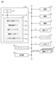
- FIG. It is a block diagram which shows the structure of the control system concerning the same embodiment.
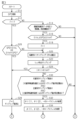
- It is a flowchart which shows the procedure of the process which the control apparatus concerning the same embodiment performs.
- It is a flowchart which shows the procedure of the process which the control apparatus concerning the same embodiment performs.
- 4 is a time chart illustrating a zero point estimation method according to the same embodiment;
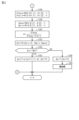
- It is a flowchart which shows the procedure of the process which the control apparatus concerning the same embodiment performs. It is a time chart for explaining the effect of the same embodiment.
- FIG. 11 is a flow chart showing the procedure of processing executed by the control device according to the second embodiment;
- FIG. FIG. 11 is a flow chart showing a procedure of processing executed by a control device according to a third embodiment;
- FIG. It is a flowchart which shows the procedure of the process which the control apparatus concerning the same embodiment performs.
- FIG. 1 exemplifies a pickup truck, which is a type of small truck, as the tractor 20 .
- the tractor 20 has front wheels 22 and rear wheels 24 .
- the front wheels 22 include two wheels, a right front wheel and a left front wheel
- the rear wheels 24 include two wheels, a right rear wheel and a left rear wheel.
- FIG. 1 illustrates a box-shaped trailer as the trailer 30 .
- the trailer 30 has wheels 32 . Wheels 32 include two wheels, a right wheel and a left wheel.
- the trailer 30 is connected to the rear of the tractor 20 via a ball joint 40.
- the ball joint 40 is a member that connects the trailer 30 to the tractor 20 so as to be rotatable about an axis 42 .
- Axis 42 extends along the height direction of tractor 20 .
- FIG. 2 shows some of the members that the tractor 20 has.
- the tractor 20 has a controller 50 .
- the control device 50 operates a steering system 60, a drive system 62, and a braking system 64 in order to control the amount of control of the articulated vehicle 10 as a controlled object.
- the controlled variables are vehicle speed, traveling direction, hitch angle, and the like.
- the hitch angle is an angle between the front-rear direction of the tractor 20 and the front-rear direction of the trailer 30 .
- the steering system 60 includes a steering actuator that steers the steered wheels.
- the steered wheels are, for example, the front wheels 22 shown in FIG.
- the steering system 60 may include a steering control device that operates a steering actuator.
- control device 50 operates steering system 60 means that control device 50 outputs a command signal to the steering control device.
- the drive system 62 includes at least one of an internal combustion engine and a rotating electrical machine as a thrust generating device for the vehicle.
- the drive system 62 may include a drive control device that controls the internal combustion engine and the rotating electric machine.
- control device 50 operates drive system 62 means that control device 50 outputs a command signal to the drive control device.
- the braking system 64 includes at least one of a device that decelerates the rotation of the wheels by frictional force and a device that decelerates the rotation of the wheels by converting the power of the wheels into electrical energy.
- the device that decelerates the rotation of the wheels by converting it into electrical energy may be shared with the rotating electric machine of the drive system.
- the braking system 64 may include a braking control device that controls a device that decelerates the rotation of the wheels. In that case, "the control device 50 operates the braking system 62" means that the control device 50 outputs a command signal to the braking control device.
- the control device 50 refers to the steering angle ⁇ t of the steered wheels detected by the steering angle sensor 70 and the yaw rate yr detected by the yaw rate sensor 72 in order to control the control amount.
- the steering angle ⁇ t is a value that has a positive sign for one of right and left turns and a negative sign for the other.
- the steering angle ⁇ t is the steering angle of the tire.
- steering angle sensor 70 may be a sensor that detects a pinion angle.
- the control device 50 executes processing for converting the pinion angle into the steering angle of the tire.
- the detection value of the steering angle sensor 70 even if the steering angle of the tire is obtained by the conversion process, it is regarded as the detection value of the steering angle sensor 70 .
- the control device 50 also refers to the hitch angle ⁇ detected by the hitch angle sensor 74 and the wheel speeds ⁇ w1 to ⁇ w4 detected by the wheel speed sensors .
- the hitch angle ⁇ can take both positive and negative signs depending on the angle between the rear-to-front direction of the tractor 20 and the rear-to-front direction of the trailer 30 .
- the sign of the hitch angle ⁇ may be positive when the direction in which the trailer 30 travels from the rear to the front deviates counterclockwise by less than 180° from the direction in which the tractor 20 travels from the rear to the front.
- the wheel speeds ⁇ w1 and ⁇ w2 are the rotational speed of the right front wheel 22 and the rotational speed of the left front wheel 22, respectively.
- the wheel speeds ⁇ w3 and ⁇ w4 are the rotational speed of the right rear wheel 24 and the rotational speed of the left rear wheel 24, respectively.
- the control device 50 sets the control amount according to the operating state of the user interface 80 .
- the user interface 80 is for transmitting a user's intention to the control device 50, such as selecting either one of automatic driving and manual driving.
- the control device 50 includes a PU 52 and a storage device 54.
- the PU 52 is a software processing device including at least one of CPU, GPU, TPU and the like.
- the storage device 54 stores a steering angle zero point estimation program 54a and a reverse assist program 54c.
- the steering angle zero point estimation program 54a prescribes a command to cause the PU 52 to execute a zero point correction process for the steering angle ⁇ t detected by the steering angle sensor 70 .
- the zero point correction process is a process of compensating for the difference between the steering angle ⁇ t and zero.
- the zero point correction process includes a process of calculating the difference between the turning angle ⁇ t and zero when the connected vehicle 10 is traveling straight. Further, the zero point correction process includes a process of correcting the sequentially sampled steering angle ⁇ t based on the calculated difference and storing it in the storage device 54 as the control steering angle data 54b.
- the steering angle data 54b for control is data relating to the steering angle ⁇ t corrected for the zero point.
- the reverse assist program 54c defines commands for processing to be executed by the PU 52 in order to automatically reverse the connected vehicle 10 .
- This processing is executed by inputting the control hitch angle data 54d, the turning angle ⁇ t, and the wheel speeds ⁇ w1 to ⁇ w4 into the storage device .
- the PU 52 operates the steering system 60, the drive system 62, and the braking system 64 to control the travel trajectory of the coupled vehicle 10 to the target travel trajectory.
- control hitch angle data 54d is data obtained by performing zero point correction of the hitch angle ⁇ detected by the hitch angle sensor 74 .
- the processing related to zero point correction of the hitch angle will be described in detail.
- FIGS. 3 and 4 show the procedure of the hitch angle zero point estimation process.
- the processing shown in FIGS. 3 and 4 is realized by the PU 52 repeatedly executing a hitch angle zero point estimation program 54e stored in the storage device 54, for example, at predetermined intervals.
- the step number of each process is represented by a number prefixed with "S".
- the PU 52 first acquires the vehicle speed SPD, which is the traveling speed of the connected vehicle 10 (S10).
- the vehicle speed SPD is calculated each time by the PU 52 based on the wheel speeds ⁇ w1 to ⁇ w4.
- the vehicle speed SPD may be, for example, a value obtained by converting the average value of the wheel speeds ⁇ w1 to ⁇ w4 into a translational speed.
- the PU 52 determines whether or not the permission flag F is "1" (S12).
- the permission flag F becomes "1" when permitting sampling of the steering angle ⁇ t and the hitch angle ⁇ to be used as an input for zero point learning of the hitch angle ⁇ . Further, the permission flag F becomes "0" when the sampling is not permitted.
- Condition (A) is a condition that the reference signal used for learning the hitch angle ⁇ is available.
- Condition (B) The condition is that the articulated vehicle 10 has traveled a predetermined distance or more after starting. In other words, the condition is that a predetermined period of time has elapsed after the vehicle started running.
- the PU 52 determines whether the condition (C) that the vehicle speed SPD is equal to or higher than the lower limit speed SthL and equal to or lower than the upper limit speed SthH is established. (S16).
- the PU 52 determines that the condition (C) is satisfied (S16: YES), it substitutes "1" for the permission flag F (S18).
- the PU 52 samples the steering angle ⁇ t (S20).
- This process includes a process of storing sampled values in an area of the storage device 54 that stores data for zero point learning.
- the steering angle ⁇ t is assumed to be the value indicated by the control steering angle data 54b stored in the storage device 54 .
- the PU 52 samples the hitch angle ⁇ detected by the hitch angle sensor 74 (S22).
- This process includes a process of storing sampled values in an area of the storage device 54 that stores data for zero point learning.
- the processing of S20 and the processing of S22 are performed in synchronization with each other. That is, the steering angle ⁇ t sampled by the process of S20 and the hitch angle ⁇ sampled by the process of S22 can be regarded as values at the same detection timing.
- the PU 52 determines whether or not the absolute value of the steering angle ⁇ t sampled by the process of S20 is greater than the learning upper limit value ⁇ thH (S24). On the other hand, when the PU 52 determines that the permission flag F is "1" (S12: YES), it determines whether or not the condition (C) is satisfied (S26). In other words, PU 52 determines whether or not the logical sum of vehicle speed SPD being less than lower limit value SthL and being greater than upper limit value SthH is true. When the PU 52 determines that the condition (C) is satisfied (S26: NO), the process proceeds to S20.
- condition (D) The condition is that the steering angle ⁇ t stored in the storage device 54 by the process of S20 has a value for right turning.
- the steering angle ⁇ t stored in the storage device 54 by the process of S20 includes a predetermined number of sampling values for which the absolute value of the steering angular velocity during right turning is equal to or less than a specified value ⁇ . be. This process is a process of determining whether or not there is a history in which the steering angle has been in a steady state during right turning.
- Condition (F) The condition is that the steering angle ⁇ t stored in the storage device 54 by the process of S20 has a value for left turning.
- the time-series data of the turning angle ⁇ t stored in the storage device 54 by the processing of S20 is converted to low-pass. Filter processing is performed (S32).
- the time-series data are expressed as " ⁇ t(1), ⁇ t(2), . . .”.
- the number in parentheses after " ⁇ t" is the sampling number. If the sampling numbers are adjacent to each other, the sampling timings are adjacent to each other.
- the PU 52 performs low-pass filter processing on the time-series data of the hitch angle ⁇ stored in the storage device 54 by the processing of S22 (S34).
- the time-series data are expressed as " ⁇ (1), ⁇ (2), . . . ".
- the low-pass filter used in the process of S32 and the low-pass filter used in the process of S34 have the same cutoff frequency.
- a dead zone may be provided in which the value near the zero point is set to zero.
- the width of the dead zone is the same in the processes of S32 and S34.
- the PU 52 substitutes the maximum value of the low-pass filtered time-series data of the turning angle ⁇ t for the maximum turning angle ⁇ tmax and substitutes the minimum value for the minimum turning angle ⁇ tmin (FIG. 4: S36).
- This process corresponds to the first acquisition process of acquiring a plurality of first detection values sampled at mutually different timings.
- the PU 52 substitutes the maximum value of the low-pass filtered time-series data of the hitch angle ⁇ for the maximum hitch angle ⁇ max, and substitutes the minimum value for the minimum hitch angle ⁇ min (S38).
- This process corresponds to the second acquisition process of acquiring a plurality of second detection values sampled in synchronization with the sampling timing of the first detection values.
- the PU 52 substitutes the value obtained by dividing the maximum steering angle ⁇ tmax by the value obtained by subtracting the minimum steering angle ⁇ tmin from the maximum steering angle ⁇ tmax for the ratio coefficient K (S40). This process corresponds to the ratio coefficient calculation process.
- the PU 52 calculates the offset amount ⁇ off0, which is the shift amount of the zero point of the hitch angle ⁇ , using the following formula (c1) (S42).
- FIG. 5 illustrates the calculation process of the offset amount ⁇ off0. In the following description, it is assumed that the value on the right turning side is positive.
- the hitch angle ⁇ When the steering angle ⁇ t is a value for turning right, the hitch angle ⁇ is a value for turning left. Further, when the steering angle ⁇ t is a value for turning left, the hitch angle ⁇ is a value for turning right.
- the hitch angle ⁇ when the zero point is correct is indicated by a dashed line.
- the solid line indicates the hitch angle ⁇ when there is an error in the zero point.
- the hitch angle ⁇ and the turning angle ⁇ t have similar waveforms, although the signs are opposite to each other. Therefore, the ratio between the maximum steering angle ⁇ tmax and the absolute value of the minimum hitch angle ⁇ min can be regarded as equal to the ratio between " ⁇ tmax ⁇ tmin" and " ⁇ max ⁇ min".
- the PU 52 determines whether or not the offset amount ⁇ off has already been calculated and stored (S44). Then, when the PU 52 determines that it is not stored yet (S44: NO), it substitutes the offset amount ⁇ off0 for the offset amount ⁇ off (S46). Then, by operating the display device 82 shown in FIG. 2, the PU 52 executes a process of displaying visual information to that effect as a process of notifying the user that the zero point learning has been performed (S48).
- the PU 52 determines that the offset amount ⁇ off is already stored (S44: YES), it updates the stored offset amount ⁇ off (S50). Specifically, the PU 52 substitutes an exponential moving average processed value of the stored offset amount ⁇ off and the offset amount ⁇ off0 newly calculated by the processing of S42 into the offset amount ⁇ off (S50).
- FIG. 4 shows an example in which the weighting factor of the offset amount ⁇ off already stored is set to " ⁇ " and the weighting factor of the offset amount ⁇ off0 newly calculated by the process of S42 is set to "1- ⁇ ". rice field. In addition, it is "0 ⁇ 1".
- the processes of S40 to S46 and S50 correspond to the zero point estimation process.
- FIG. 6 shows the procedure for updating the control hitch angle data 54d.
- the processing shown in FIG. 6 is realized by the PU 52 repeatedly executing a hitch angle zero point estimation program 54e stored in the storage device 54, for example, at a sampling period of the hitch angle ⁇ .
- the PU 52 first determines whether or not the offset amount ⁇ off is already stored (S60). If the PU 52 determines that it has already been stored (S60: YES), it acquires the latest sampled value of the hitch angle ⁇ (S62). Next, the PU 52 substitutes the hitch angle ⁇ with a value obtained by subtracting the offset amount ⁇ off from the hitch angle ⁇ (S64). This processing corresponds to zero point correction processing. Then, the PU 52 updates the control hitch angle data 54d stored in the storage device 54 to the value calculated by the process of S64 (S66).
- the PU 52 temporarily terminates the series of processes shown in FIG. 6 when completing the process of S66 and when making a negative determination in the process of S60. "Action and effect of the present embodiment" After detecting the zero point of the steering angle ⁇ t, the PU 52 calculates the offset amount ⁇ off, which is the error of the zero point of the hitch angle ⁇ , based on the similarity between the waveform data of the steering angle ⁇ t and the waveform data of the hitch angle ⁇ . do. As a result, the zero point of the hitch angle ⁇ can be detected even when the articulated vehicle 10 is not traveling straight ahead.
- the PU 52 estimated the zero point of the hitch angle sensor 74 using both the hitch angle ⁇ sampled during right turning and the hitch angle ⁇ sampled during left turning. Therefore, compared to the case where only one of the hitch angle ⁇ sampled when the vehicle turns right and the hitch angle ⁇ sampled when the vehicle turns left is included, there is a large difference between the two hitch angles ⁇ . Therefore, the SN ratio can be improved as compared with the case where only one of the above is included.
- the PU 52 calculated the offset amount ⁇ off based on the sampling values of the steering angle ⁇ t and the hitch angle ⁇ in both the steady state of right turning and the steady state of left turning. As a result, the accuracy of calculating the offset amount ⁇ off can be improved as compared with the case of using the sampled values when the steady state does not occur.
- FIG. 7 shows changes in the steering angle ⁇ t, hitch angle ⁇ , ratio coefficient K, and offset amount ⁇ off.
- the offset amount ⁇ off indicates a case where the offset amount ⁇ off is calculated without including the conditions (E) and (G).
- the offset amount ⁇ off during the period T1 in which the turning is not steady deviates from the true value indicated by the dashed-dotted line in the figure.
- the PU 52 calculates the offset amount ⁇ off based on the sampling values of the steering angle ⁇ t and the hitch angle ⁇ when the absolute value of the steering angle ⁇ t is equal to or less than the learning upper limit value ⁇ thH. As a result, the accuracy of calculating the offset amount ⁇ off can be improved as compared with the case of using the sampling value when the absolute value of the turning angle ⁇ t is larger than the learning upper limit value ⁇ thH.
- a period T2 in FIG. 7 shows a case where the offset amount ⁇ off is calculated even when the absolute value of the turning angle ⁇ t is larger than the learning upper limit value ⁇ thH.
- the offset amount ⁇ off during the period T2 in which the absolute value of the turning angle ⁇ t is large deviates from the true value indicated by the dashed-dotted line in the figure.
- the PU 52 performs zero point correction of the hitch angle ⁇ that is sampled each time, and updates the control hitch angle data 54d.
- the PU 52 uses the control hitch angle data 54d when performing control using the hitch angle ⁇ , such as when executing the reverse assist program 54c. As a result, it is possible to suppress the influence of the error of the hitch angle sensor 74 on the control.
- the processing in which the PU 52 operates a predetermined device according to the reverse assist program 54c corresponds to the operation processing in which the predetermined device is operated based on the second detection value corrected by the zero point correction processing.
- the predetermined device corresponds to the steering system 60 and the like.
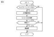
- FIG. 8 shows the procedure of the zero point estimation process according to this embodiment. The processing shown in FIG. 8 is implemented by the PU 52 repeatedly executing a hitch angle zero point estimation program 54e stored in the storage device 54, for example, at predetermined intervals.
- the PU 52 first determines whether or not the calibration mode is ON (S70).
- This process is a process of determining whether or not the user has selected driving for the zero point learning process of the hitch angle ⁇ . That is, when the zero point of the hitch angle ⁇ is learned by the above-described processing of S40, S42, etc., the PU 52 operates the display device 82 to notify that effect. Therefore, when the zero point of the hitch angle ⁇ has not been learned, the user can know from the information on the display device 82 that learning has not been done. In this embodiment, the user is allowed to select intentional driving for zero point learning. This can be accomplished by manipulating the user interface 80 and selecting a calibration mode.
- the PU 52 determines that the calibration mode is ON (S70: YES), it operates the display device 82 to indicate the travel locus (S72).
- This process corresponds to the instruction process.
- it is sufficient to instruct the travel route to switch from turning right to turning left. Further, for example, a travel route to switch from turning left to turning right may be instructed.
- the PU 52 then executes the processes of S10 to S46 described in FIGS. And PU52 determines whether learning was completed (S74). In other words, the PU 52 determines whether or not the processing up to S46 has been completed.
- the user drives for which a negative determination is made in the processes of S14, S16, and S30, or drives for which a positive determination is made in the process of S24, the learning is not completed.
- the steering angle ⁇ t corrected for zero point is used as the reference signal.
- the yaw rate yr corrected for the zero point is used as the reference signal.
- the zero point correction of the yaw rate yr is performed in the same manner as the zero point correction of the turning angle ⁇ t.
- FIGS. 9 and 10 show the procedure of the hitch angle zero point correction process according to the present embodiment.
- the processing shown in FIGS. 9 and 10 is implemented by the PU 52 repeatedly executing a hitch angle zero point estimation program 54e stored in the storage device 54, for example, at predetermined intervals.
- 9 and 10 processes corresponding to the processes described in FIGS. 3 and 4 are assigned the same step numbers, and the description thereof is omitted.
- the PU 52 executes a process of sampling the yaw rate yr instead of the process of S20 (S20a). If a negative determination is made in the process of S24, the PU 52 determines whether or not the AND of the following conditions (D1), (F1), (H), and (I) is true (S30a). .
- Condition (D1) The condition is that the yaw rate yr stored in the storage device 54 by the process of S20a has a value for right turning.
- Condition (F1) The condition is that the yaw rate yr stored in the storage device 54 by the process of S20a has a value for left turning.
- Condition (H) A condition that the absolute value of the sampled value of the yaw rate yr during right turning is equal to or less than the specified value ⁇ .
- the PU 52 determines that the logical product is true (S30a: YES), it low-pass filters the time-series data of the yaw rate yr stored in the storage device 54 by the processing of S20a (S32a). In FIG. 9, the time-series data are expressed as "yr(1), yr(2), ". Moreover, PU52 performs the process of S34.
- the low-pass filter used for the processing of S32a and the low-pass filter used for the processing of S34 have the same cutoff frequency.
- a dead zone may be provided in which the value near the zero point is set to zero.
- the width of the dead zone is the same in the processes of S32a and S34.
- the PU 52 When completing the process of S34, the PU 52 substitutes the maximum value of the low-pass filtered time-series data of the yaw rate yr for the maximum yaw rate yrmax and the minimum value for the minimum yaw rate yrmin (S36a: FIG. 10). Note that this process corresponds to the first acquisition process.
- the PU 52 substitutes the value obtained by dividing the maximum yaw rate yrmax by the value obtained by subtracting the minimum yaw rate yrmin from the maximum yaw rate yrmax for the ratio coefficient K (S40a). This process corresponds to the ratio coefficient calculation process.
- PU 52 executes the processes of S42 to S50.
- the processing of S40a, S42 to S46, S50 corresponds to zero point correction processing.
- this embodiment can be changed and implemented as follows. This embodiment and the following modifications can be implemented in combination with each other within a technically consistent range.
- the first sensor may be the yaw rate sensor 72 and the second sensor may be the steering angle sensor 70 .
- the combination of the first sensor and the second sensor is not limited to a combination of any two of the steering angle sensor 70, the yaw rate sensor 72, and the hitch angle sensor 74.
- the second sensor may be either an acceleration sensor that detects lateral acceleration or the wheel speed sensor 76 .
- either the steering angle sensor 70 or the yaw rate sensor 72 may be used as the first sensor.
- the detection value to be subjected to zero point correction is the difference between the wheel speeds ⁇ w1 and ⁇ w2 of the front wheels, or the difference between the wheel speeds ⁇ w3 and ⁇ w4 of the rear wheels.
- Speed difference This is a physical quantity having a correlation with the yaw rate and the like.
- the maximum absolute value of the steering angle ⁇ t during left turning and right turning is the maximum value of the magnitude of the first detection value during left turning
- the first detection value when turning left and the first detection value when turning right may be acquired without being particular about the maximum value.
- a first detection value when turning left or right and a first detection value when traveling straight may be acquired.
- two first detection values having different magnitudes sampled when turning right or when turning left may be used.
- the two first detection values differ in magnitude (absolute value) of the sampled values by a threshold value or more. Furthermore, it is not essential that the two first detection values that differ in magnitude of the sampled values by a threshold value or more are the first detection values sampled during either one of the periods of turning right and turning left. . Note that the process of determining whether the conditions (D) and (F) are met in the process of S30 in FIG. This is an example.
- the steering angle ⁇ t or yaw rate yr and the hitch angle ⁇ are synchronously sampled, and then their maximum and minimum values are extracted.
- the maximum and minimum values of the steering angle ⁇ t or yaw rate yr and the minimum and maximum values of the hitch angle ⁇ are regarded as synchronous sampling values.
- the logic is not limited to this, and the logic may be such that only values sampled in synchronization with each other are extracted.
- the hitch angle ⁇ to be acquired by the second acquisition process is the value obtained by low-pass filtering the sensor value, but the present invention is not limited to this.
- high-pass filtering may be further applied.
- Detection values to be acquired are not limited to low-pass filtered values.
- the first acquisition process is not limited to the process of acquiring two detection values. For example, as described in the section "Regarding Zero Point Estimation Processing", when using LDS or the like, detection values may be acquired sequentially.
- the ratio coefficient K is the ratio of the maximum value to the difference between the maximum value and the minimum value of the first sensor, but it is not limited to this. For example, it may be the ratio of the difference between the maximum value and the minimum value of the first sensor and the minimum value.
- the ratio coefficient K be the ratio of the difference between the maximum and minimum values of the first detection values and the maximum or minimum value.
- the ratio coefficient may be used as the ratio coefficient.
- the magnitude of the first detection value is set to
- the process of converting to the magnitude of the two detection values is not limited to the process exemplified in the above embodiment.
- the ratio of the difference between two values of the time-series data of the turning angle ⁇ t and the difference between the corresponding values of the hitch angle ⁇ can be changed by changing the two different values. It can be calculated as follows. Then, it may be used in the process of converting the average value of each of these ratios.
- the offset amount ⁇ off may be the average value of the differences between these values and the corresponding hitch angles ⁇ (1), ⁇ (2), .
- the first detection is performed according to the ratio between the amount of change in the first detection value indicated by the plurality of first detection values and the amount of change in the second detection value indicated by the plurality of second detection values. It is not essential that the process converts the magnitude of the value into the magnitude of the second detection value.
- the hitch angle ⁇ when the turning angle ⁇ t becomes zero may be set as the offset amount ⁇ off.
- the hitch angle ⁇ estimated by inputting the time-series data of the turning angle ⁇ t and the corresponding time-series data of the hitch angle ⁇ into a trained model such as a linear dynamic system (LDS) may be In that case, the difference between the true value and the detected hitch angle ⁇ may be taken as the offset amount ⁇ off.
- the training data of the learned model is obtained by using the steering angle ⁇ t with zero point correction and the hitch angle ⁇ without zero point correction as input variables and the hitch angle ⁇ with zero point correction as the target variable.
- This learned model is a model in which the similarity between the waveform of the time-series data of the steering angle ⁇ t and the waveform of the time-series data of the hitch angle ⁇ has been learned. Further, the output of the learned model may be set to the offset amount ⁇ off instead of the hitch angle ⁇ .
- the control device is not limited to one that includes the PU 52 and the storage device 54 and executes software processing.
- the control device may comprise, for example, a dedicated hardware circuit such as an ASIC that performs hardware processing at least part of what is software processed in the above embodiments. That is, the control device may include a processing circuit having any one of the following configurations (a) to (c).
- a processing circuit comprising a processing device for executing all of the above processes according to a program and a program storage device such as a storage device for storing the program.
- a processing circuit comprising a processing device and a program storage device for executing part of the above processing according to a program, and a dedicated hardware circuit for executing the remaining processing.
- processing circuitry comprising dedicated hardware circuitry for performing all of the above processing;
- processing circuitry comprising dedicated hardware circuitry for performing all of the above processing;
- ABS vehicle The connected vehicle is not limited to the vehicle illustrated in FIG.
- the vehicle is not limited to an articulated vehicle.
Landscapes
- Engineering & Computer Science (AREA)
- Transportation (AREA)
- Mechanical Engineering (AREA)
- Combustion & Propulsion (AREA)
- Chemical & Material Sciences (AREA)
- Automation & Control Theory (AREA)
- Physics & Mathematics (AREA)
- General Physics & Mathematics (AREA)
- Mathematical Physics (AREA)
- Human Computer Interaction (AREA)
- Radar, Positioning & Navigation (AREA)
- Remote Sensing (AREA)
- Steering Control In Accordance With Driving Conditions (AREA)
- Indication And Recording Devices For Special Purposes And Tariff Metering Devices (AREA)
- Gyroscopes (AREA)
Abstract
Description
以下、第1の実施形態について図面を参照しつつ説明する。
「連結車両の構成」
図1に示すように、連結車両10は、トラクタ20およびトレーラ30を有している。図1には、トラクタ20として、小型貨物自動車の一種であるピックアップトラックを例示する。トラクタ20は、前輪22および後輪24を備える。前輪22は右前輪および左前輪の2輪を含み、後輪24は右後輪および左後輪の2輪を含む。また、図1には、トレーラ30として、箱型のトレーラを例示する。トレーラ30は、車輪32を有している。車輪32は、右車輪および左車輪の2輪を含む。
図3および図4に、ヒッチ角のゼロ点推定処理の手順を示す。図3および図4に示す処理は、記憶装置54に記憶されたヒッチ角ゼロ点推定プログラム54eをPU52がたとえば所定周期で繰り返し実行することによって実現される。なお、以下では、先頭に「S」が付与された数字によって各処理のステップ番号を表現する。
条件(A):転舵角θtのゼロ点学習がなされており、制御用転舵角データ54bが逐次更新されている状態である旨の条件である。条件(A)は、ヒッチ角βの学習に用いる基準信号を利用可能な状態である旨の条件である。
PU52は、論理積が真であると判定する場合(S14:YES)、車速SPDが下限速度SthL以上であって且つ上限速度SthH以下である旨の条件(C)が成立するか否かを判定する(S16)。PU52は、条件(C)が成立すると判定する場合(S16:YES)、許可フラグFに「1」を代入する(S18)。
一方、PU52は、許可フラグFが「1」であると判定する場合(S12:YES)、上記条件(C)が成立しないか否かを判定する(S26)。換言すれば、PU52は、車速SPDが下限値SthL未満であることと上限値SthHよりも大きいこととの論理和が真であるか否かを判定する。PU52は、条件(C)が成立すると判定する場合(S26:NO)、S20の処理に移行する。一方、PU52は、条件(C)が成立しないと判定する場合(S26:YES)と、S24の処理において肯定判定する場合とには、許可フラグFに「0」を代入して且つ、S20,S22の処理によってサンプリングされたデータを消去する(S28)。
条件(D):S20の処理によって記憶装置54に記憶された転舵角θtに、右旋回時の値がある旨の条件である。
条件(G):S20の処理によって記憶装置54に記憶された転舵角θtに、左旋回時の転舵角速度の絶対値が規定値Δ以下であるサンプリング値が所定数ある旨の条件である。この処理は、左旋回中に転舵角が定常状態となった履歴があるか否かを判定する処理である。
図5に、オフセット量βoff0の算出処理を例示する。なお、以下では、右旋回側の値を正として説明する。
θtmax・(βmax-βmin)/(θtmax-θtmin)
したがって、ゼロ点誤差がない最小ヒッチ角は、以下の式となる。
オフセット量βoff0は、サンプリングされた最小ヒッチ角βminと上記ゼロ点誤差がない最小ヒッチ角との差であることから、式(c1)の右辺に等しい。
「本実施形態の作用および効果」
PU52は、転舵角θtのゼロ点の検出後、転舵角θtの波形データとヒッチ角βの波形データとの相似性に基づき、ヒッチ角βのゼロ点の誤差であるオフセット量βoffを算出する。これにより、連結車両10が直進走行していない場合であっても、ヒッチ角βのゼロ点を検出できる。
(1)PU52は、右旋回時にサンプリングされたヒッチ角βと左旋回時にサンプリングされたヒッチ角βとの双方を用いて、ヒッチ角センサ74のゼロ点を推定した。そのため、車両の右旋回時にサンプリングされたヒッチ角βと左旋回時にサンプリングされたヒッチ角βとのいずれか一方のみを含む場合と比較すると、2つのヒッチ角β同士に大きな差が生じる。したがって、上記いずれか一方のみを含む場合と比較して、SN比を向上させることができる。
以下、第2の実施形態について、第1の実施形態との相違点を中心に図面を参照しつつ説明する。
図8に、本実施形態にかかるゼロ点の推定処理の手順を示す。図8に示す処理は、記憶装置54に記憶されたヒッチ角ゼロ点推定プログラム54eをPU52がたとえば所定周期でくり返し実行することにより実現される。
<第3の実施形態>
以下、第3の実施形態について、第1の実施形態との相違点を中心に図面を参照しつつ説明する。
条件(F1):S20aの処理によって記憶装置54に記憶されたヨーレートyrに、左旋回時の値がある旨の条件である。
条件(I):左旋回時のヨーレートyrのサンプリング値に、その絶対値が規定値Δ以下のものがある旨の条件である。
<その他の実施形態>
なお、本実施形態は、以下のように変更して実施することができる。本実施形態および以下の変更例は、技術的に矛盾しない範囲で互いに組み合わせて実施することができる。
・第1センサおよび第2センサの組み合わせとしては、上記実施形態において例示したものに限らない。たとえば、第1センサを、ヨーレートセンサ72として且つ、第2センサを、舵角センサ70としてもよい。
・上記実施形態では、左旋回時および右旋回時のそれぞれにおける転舵角θtの絶対値の最大値等、左旋回時の第1検出値の大きさの最大値と、右旋回時の第1検出値の大きさの最大値と、を取得したが、これに限らない。たとえば最大値に特にこだわることなく、左旋回時の第1検出値と、右旋回時の第1検出値と、を取得してもよい。また、たとえば、左旋回時または右旋回時の第1検出値と、直進時の第1検出値とを取得してもよい。さらにたとえば、右旋回時または左旋回時においてサンプリングされた大きさが互いに異なる2つの第1検出値であってもよい。この際、サンプリングされた値の大きさ(絶対値)が閾値以上異なる2つの第1検出値とすることが望ましい。さらに、サンプリングされた値の大きさが閾値以上異なる2つの第1検出値が、右旋回時および左旋回時のいずれか一方の期間にサンプリングされた第1検出値であることも必須ではない。なお、図3のS30の処理における条件(D)および条件(F)の成立の有無の判定処理は、サンプリングされた値の大きさ(絶対値)が閾値以上異なるか否かを判定する処理の一例となっている。
・第1取得処理としては、2個の検出値を取得する処理に限らない。たとえば、「ゼロ点推定処理について」の欄に記載したように、LDSを用いる場合等には、逐次検出値を取得してもよい。
・上記実施形態では、比率係数Kを、第1センサの最大値と最小値との差と、最大値との比としたが、これに限らない。たとえば、第1センサの最大値と最小値との差と、最小値との比としてもよい。
・制御装置としては、PU52と記憶装置54とを備えて、ソフトウェア処理を実行するものに限らない。制御装置は、たとえば、上記実施形態においてソフトウェア処理されたものの少なくとも一部を、ハードウェア処理するたとえばASIC等の専用のハードウェア回路を備えてもよい。すなわち、制御装置は、以下の(a)~(c)のいずれかの構成を有する処理回路を備えていればよい。
(b)上記処理の一部をプログラムに従って実行する処理装置およびプログラム格納装置と、残りの処理を実行する専用のハードウェア回路とを備える処理回路。
ここで、処理装置およびプログラム格納装置を備えたソフトウェア実行装置や、専用のハードウェア回路は複数であってもよい。
・連結車両としては、図1に例示した車両に限らない。車両としては、連結車両に限らない。
Claims (12)
- 第1センサおよび第2センサを備えた車両に適用されるゼロ点推定装置であって、
前記第1センサは、前記車両のヨー運動に応じて変化する物理量を検出するように構成され、
前記第2センサは、前記車両のヨー運動に応じて変化する物理量であって且つ前記第1センサの検出対象とは異なる物理量を検出するように構成され、
前記第1センサは、ゼロ点補正がなされており、
前記ゼロ点推定装置は、第1取得処理、第2取得処理、およびゼロ点推定処理を実行するように構成され、
前記第1取得処理は、前記車両が進行方向の変更を含む走行をしている状態において、互いに異なるタイミングにおいてサンプリングされた複数個の第1検出値を取得する処理であり、
前記第1検出値は、前記第1センサの検出値であり、
前記第2取得処理は、前記第1取得処理による取得対象となる前記第1検出値のサンプリングタイミングに同期してサンプリングされた複数個の第2検出値を取得する処理であり、
前記第2検出値は、前記第2センサの検出値であり、
前記ゼロ点推定処理は、前記第1取得処理によって取得された複数個の前記第1検出値および前記第2取得処理によって取得された複数個の前記第2検出値を入力として、前記第2センサのゼロ点を推定する処理であるゼロ点推定装置。 - 前記第1取得処理によって取得された複数個の前記第1検出値は、前記車両の舵角が互いに相違するタイミングにおいてサンプリングされた値を含む請求項1記載のゼロ点推定装置。
- 前記第1取得処理によって取得された複数個の前記第1検出値は、互いの大きさが閾値以上異なる2つの第1検出値を含む請求項1または2記載のゼロ点推定装置。
- 前記第1取得処理によって取得された複数個の前記第1検出値は、前記車両の右旋回時にサンプリングされた値と前記車両の左旋回時にサンプリングされた値とを含む請求項1~3のいずれか1項に記載のゼロ点推定装置。
- 前記車両は、転舵輪の転舵角を操作可能なトラクタであり、
前記トラクタには、当該トラクタによって牽引されるトレーラが連結可能とされ、
前記第1センサおよび前記第2センサのいずれかは、ヒッチ角センサであり、
前記ヒッチ角センサは、前記トラクタの前後方向と前記トレーラの前後方向とのなす角度であるヒッチ角を検出するように構成され、
前記第1取得処理による取得対象となる前記第1検出値のサンプリングを、前記車両の走行開始後所定期間経過することを条件に実行するように構成されている請求項1~4のいずれか1項に記載のゼロ点推定装置。 - 前記ゼロ点推定処理は、複数個の前記第1検出値が示す前記第1検出値の変化量と複数個の前記第2検出値が示す前記第2検出値の変化量との比に応じて、前記第1検出値の大きさを前記第2検出値の大きさに変換することによって、前記ゼロ点を算出する処理である請求項1~5のいずれか1項に記載のゼロ点推定装置。
- 前記ゼロ点推定処理は、
2個の前記第1検出値同士の差と所定第1検出値との比である比率係数を算出する比率係数算出処理と、
2個の前記第2検出値同士の差と前記比率係数との積に応じて第2検出値の推定値を算出する処理と、を含み、
前記所定第1検出値は、複数個の前記第1検出値のうちのゼロ点ではない検出値であり、
前記2個の前記第2検出値は、前記2個の前記第1検出値に対応する前記第2検出値である請求項6記載のゼロ点推定装置。 - ゼロ点補正処理、および操作処理を実行するように構成され、
前記ゼロ点補正処理は、前記ゼロ点推定処理によって推定されたゼロ点に応じて前記第2検出値を補正する処理であり、
前記操作処理は、前記ゼロ点補正処理によって補正された前記第2検出値に基づき、所定の機器を操作する処理である請求項1~7のいずれか1項に記載のゼロ点推定装置。 - 前記車両のユーザに前記車両を所定の運転条件で運転するように指示する指示処理を実行するように構成され、
前記所定の運転条件は、前記車両の進行方向を変化させる運転条件であり、
前記第1取得処理を、前記指示処理の後の前記車両の運転時に実行するように構成されている請求項1~8のいずれか1項に記載のゼロ点推定装置。 - 前記車両は、転舵輪の転舵角を操作可能なトラクタであり、
前記トラクタには、当該トラクタによって牽引されるトレーラが連結可能とされ、
前記第1センサおよび前記第2センサは、舵角センサ、ヨーレートセンサ、およびヒッチ角センサの3つのセンサのうちのいずれか2つであり、
前記ヒッチ角センサは、前記トラクタの前後方向と前記トレーラの前後方向とのなす角度であるヒッチ角を検出するように構成されている請求項1~9のいずれか1項に記載のゼロ点推定装置。 - 第1センサおよび第2センサを備えた車両に適用されるゼロ点推定方法であって、
前記第1センサは、前記車両のヨー運動に応じて変化する物理量を検出するように構成され、
前記第2センサは、前記車両のヨー運動に応じて変化する物理量であって且つ前記第1センサの検出対象とは異なる物理量を検出するように構成され、
前記第1センサは、ゼロ点補正がなされており、
前記ゼロ点推定方法は、第1取得処理を実行すること、第2取得処理を実行すること、およびゼロ点推定処理を実行することを含み、
前記第1取得処理は、前記車両が進行方向の変更を含む走行をしている状態において、互いに異なるタイミングにおいてサンプリングされた複数個の第1検出値を取得する処理であり、
前記第1検出値は、前記第1センサの検出値であり、
前記第2取得処理は、前記第1取得処理による取得対象となる前記第1検出値のサンプリングタイミングに同期してサンプリングされた複数個の第2検出値を取得する処理であり、
前記第2検出値は、前記第2センサの検出値であり、
前記ゼロ点推定処理は、前記第1取得処理によって取得された複数個の前記第1検出値および前記第2取得処理によって取得された複数個の前記第2検出値を入力として、前記第2センサのゼロ点を推定する処理であるゼロ点推定方法。 - 第1センサおよび第2センサを備えた車両に適用されるゼロ点推定プログラムであって、
前記第1センサは、前記車両のヨー運動に応じて変化する物理量を検出するように構成され、
前記第2センサは、前記車両のヨー運動に応じて変化する物理量であって且つ前記第1センサの検出対象とは異なる物理量を検出するように構成され、
前記第1センサは、ゼロ点補正がなされており、
前記ゼロ点推定プログラムは、第1取得処理、第2取得処理、およびゼロ点推定処理をコンピュータに実行させる指令を有し、
前記第1取得処理は、前記車両が進行方向の変更を含む走行をしている状態において、互いに異なるタイミングにおいてサンプリングされた複数個の第1検出値を取得する処理であり、
前記第1検出値は、前記第1センサの検出値であり、
前記第2取得処理は、前記第1取得処理による取得対象となる前記第1検出値のサンプリングタイミングに同期してサンプリングされた複数個の第2検出値を取得する処理であり、
前記第2検出値は、前記第2センサの検出値であり、
前記ゼロ点推定処理は、前記第1取得処理によって取得された複数個の前記第1検出値および前記第2取得処理によって取得された複数個の前記第2検出値を入力として、前記第2センサのゼロ点を推定する処理であるゼロ点推定プログラム。
Priority Applications (1)
| Application Number | Priority Date | Filing Date | Title |
|---|---|---|---|
| US18/726,527 US12522222B2 (en) | 2022-01-11 | 2022-12-27 | Zero point estimation device, zero point estimation method, and non-transitory computer-readable medium |
Applications Claiming Priority (2)
| Application Number | Priority Date | Filing Date | Title |
|---|---|---|---|
| JP2022002354A JP7734080B2 (ja) | 2022-01-11 | 2022-01-11 | ゼロ点推定装置、ゼロ点推定方法、およびゼロ点推定プログラム |
| JP2022-002354 | 2022-01-11 |
Publications (1)
| Publication Number | Publication Date |
|---|---|
| WO2023136129A1 true WO2023136129A1 (ja) | 2023-07-20 |
Family
ID=87279081
Family Applications (1)
| Application Number | Title | Priority Date | Filing Date |
|---|---|---|---|
| PCT/JP2022/048079 Ceased WO2023136129A1 (ja) | 2022-01-11 | 2022-12-27 | ゼロ点推定装置、ゼロ点推定方法、およびゼロ点推定プログラム |
Country Status (3)
| Country | Link |
|---|---|
| US (1) | US12522222B2 (ja) |
| JP (1) | JP7734080B2 (ja) |
| WO (1) | WO2023136129A1 (ja) |
Citations (4)
| Publication number | Priority date | Publication date | Assignee | Title |
|---|---|---|---|---|
| JP2012063184A (ja) * | 2010-09-15 | 2012-03-29 | Honda Motor Co Ltd | ヨーレート較正装置 |
| US20160039456A1 (en) * | 2011-04-19 | 2016-02-11 | Ford Global Technologies, Llc | Trailer backup offset determination |
| US20170297619A1 (en) * | 2016-04-13 | 2017-10-19 | Ford Global Technologies, Llc | Target-based trailer backup collision mitigation |
| WO2020234440A1 (en) * | 2019-05-23 | 2020-11-26 | Jaguar Land Rover Limited | Vehicle control system and method |
Family Cites Families (9)
| Publication number | Priority date | Publication date | Assignee | Title |
|---|---|---|---|---|
| JPH09226556A (ja) * | 1996-02-21 | 1997-09-02 | Aisin Seiki Co Ltd | 車両の運動制御装置 |
| US9290202B2 (en) | 2011-04-19 | 2016-03-22 | Ford Global Technologies, Llc | System and method of calibrating a trailer backup assist system |
| JP6369399B2 (ja) * | 2015-06-26 | 2018-08-08 | 株式会社デンソー | センサ出力補正装置 |
| EP3219567B1 (en) * | 2016-03-14 | 2025-02-19 | Honda Research Institute Europe GmbH | Method, system and vehicle for analyzing a rider performance |
| JP6531768B2 (ja) * | 2017-01-13 | 2019-06-19 | トヨタ自動車株式会社 | センサ誤差補正装置及び方法 |
| JP6877854B2 (ja) * | 2017-01-30 | 2021-05-26 | 三菱電機株式会社 | 測位装置および測位方法 |
| US10552976B2 (en) * | 2017-03-22 | 2020-02-04 | Magna Electronics Inc. | Trailer angle detection system for vehicle |
| JP6977629B2 (ja) * | 2018-03-09 | 2021-12-08 | 株式会社デンソー | 車両の運転支援制御装置、車両の運転支援システムおよび車両の運転支援制御方法 |
| US12384295B2 (en) * | 2021-01-05 | 2025-08-12 | Magna Electronics Inc. | Vehicular trailer angle detection system for fifth-wheel trailers |
-
2022
- 2022-01-11 JP JP2022002354A patent/JP7734080B2/ja active Active
- 2022-12-27 US US18/726,527 patent/US12522222B2/en active Active
- 2022-12-27 WO PCT/JP2022/048079 patent/WO2023136129A1/ja not_active Ceased
Patent Citations (4)
| Publication number | Priority date | Publication date | Assignee | Title |
|---|---|---|---|---|
| JP2012063184A (ja) * | 2010-09-15 | 2012-03-29 | Honda Motor Co Ltd | ヨーレート較正装置 |
| US20160039456A1 (en) * | 2011-04-19 | 2016-02-11 | Ford Global Technologies, Llc | Trailer backup offset determination |
| US20170297619A1 (en) * | 2016-04-13 | 2017-10-19 | Ford Global Technologies, Llc | Target-based trailer backup collision mitigation |
| WO2020234440A1 (en) * | 2019-05-23 | 2020-11-26 | Jaguar Land Rover Limited | Vehicle control system and method |
Also Published As
| Publication number | Publication date |
|---|---|
| JP7734080B2 (ja) | 2025-09-04 |
| US12522222B2 (en) | 2026-01-13 |
| US20250026357A1 (en) | 2025-01-23 |
| JP2023102030A (ja) | 2023-07-24 |
Similar Documents
| Publication | Publication Date | Title |
|---|---|---|
| CN106945717B (zh) | 车辆的操舵反力控制装置 | |
| JP5055933B2 (ja) | 走行支援装置 | |
| JP5316599B2 (ja) | 操舵装置及び操舵制御装置 | |
| JP6419671B2 (ja) | 車両用操舵装置および車両用操舵方法 | |
| JP2016088436A (ja) | モータ制御装置 | |
| JP5359200B2 (ja) | 車両操舵制御装置 | |
| JPH05185947A (ja) | 車両の走行特性制御装置 | |
| CN109204457A (zh) | 确定用于机动车辆应用的转向角 | |
| KR20180019820A (ko) | 전동식 조향 시스템의 제어 장치 및 제어 방법 | |
| WO2023228854A1 (ja) | 連結車両の制御装置、連結車両の制御方法、および連結車両の制御プログラム | |
| JP3896995B2 (ja) | 車両用走行支援装置 | |
| EP3939861B1 (en) | Steering device | |
| WO2023136129A1 (ja) | ゼロ点推定装置、ゼロ点推定方法、およびゼロ点推定プログラム | |
| JP2010162958A (ja) | 車両制御装置 | |
| JP2014218192A (ja) | 車両用操舵制御装置及び車両用操舵制御方法 | |
| US20250121877A1 (en) | Steering control device | |
| JP2007253770A (ja) | 車両用支援制御装置 | |
| CN119840707A (zh) | 转向操纵控制装置 | |
| JP4692403B2 (ja) | 車両の操舵装置 | |
| JP3896994B2 (ja) | 車両用走行支援装置 | |
| WO2023132290A1 (ja) | ジャックナイフ抑制装置、ジャックナイフ抑制方法、およびジャックナイフ抑制プログラム | |
| WO2023243368A1 (ja) | 連結車両の制御装置、連結車両の制御方法、および連結車両の制御プログラム | |
| CN114802424A (zh) | 转向补偿方法、装置、设备及介质 | |
| JP2003026023A (ja) | 車線追従走行制御装置 | |
| JP4240013B2 (ja) | 操舵支援装置 |
Legal Events
| Date | Code | Title | Description |
|---|---|---|---|
| 121 | Ep: the epo has been informed by wipo that ep was designated in this application |
Ref document number: 22920645 Country of ref document: EP Kind code of ref document: A1 |
|
| WWE | Wipo information: entry into national phase |
Ref document number: 18726527 Country of ref document: US |
|
| NENP | Non-entry into the national phase |
Ref country code: DE |
|
| 122 | Ep: pct application non-entry in european phase |
Ref document number: 22920645 Country of ref document: EP Kind code of ref document: A1 |
|
| WWG | Wipo information: grant in national office |
Ref document number: 18726527 Country of ref document: US |