WO2023135881A1 - センサ装置 - Google Patents
センサ装置 Download PDFInfo
- Publication number
- WO2023135881A1 WO2023135881A1 PCT/JP2022/038685 JP2022038685W WO2023135881A1 WO 2023135881 A1 WO2023135881 A1 WO 2023135881A1 JP 2022038685 W JP2022038685 W JP 2022038685W WO 2023135881 A1 WO2023135881 A1 WO 2023135881A1
- Authority
- WO
- WIPO (PCT)
- Prior art keywords
- sensor
- electrode
- voltage
- shield electrode
- sensor electrode
- Prior art date
Links
- 239000000758 substrate Substances 0.000 claims description 22
- 230000002093 peripheral effect Effects 0.000 claims description 7
- 230000005611 electricity Effects 0.000 abstract description 32
- 230000003068 static effect Effects 0.000 abstract description 32
- 238000001514 detection method Methods 0.000 abstract description 24
- 238000013459 approach Methods 0.000 abstract description 12
- 239000000463 material Substances 0.000 abstract description 5
- 238000010586 diagram Methods 0.000 description 23
- 238000012986 modification Methods 0.000 description 9
- 230000004048 modification Effects 0.000 description 9
- 230000015556 catabolic process Effects 0.000 description 7
- 229910052751 metal Inorganic materials 0.000 description 3
- 239000002184 metal Substances 0.000 description 3
- 230000007935 neutral effect Effects 0.000 description 3
- 239000004020 conductor Substances 0.000 description 2
- 230000008878 coupling Effects 0.000 description 2
- 238000010168 coupling process Methods 0.000 description 2
- 238000005859 coupling reaction Methods 0.000 description 2
- 230000000694 effects Effects 0.000 description 2
- 230000035945 sensitivity Effects 0.000 description 2
- RYGMFSIKBFXOCR-UHFFFAOYSA-N Copper Chemical compound [Cu] RYGMFSIKBFXOCR-UHFFFAOYSA-N 0.000 description 1
- 239000004642 Polyimide Substances 0.000 description 1
- 230000004308 accommodation Effects 0.000 description 1
- 229910052782 aluminium Inorganic materials 0.000 description 1
- XAGFODPZIPBFFR-UHFFFAOYSA-N aluminium Chemical compound [Al] XAGFODPZIPBFFR-UHFFFAOYSA-N 0.000 description 1
- 239000003990 capacitor Substances 0.000 description 1
- 238000004891 communication Methods 0.000 description 1
- 230000000052 comparative effect Effects 0.000 description 1
- 229910052802 copper Inorganic materials 0.000 description 1
- 239000010949 copper Substances 0.000 description 1
- 238000010438 heat treatment Methods 0.000 description 1
- 230000001771 impaired effect Effects 0.000 description 1
- 238000000034 method Methods 0.000 description 1
- 229920001721 polyimide Polymers 0.000 description 1
- 238000012545 processing Methods 0.000 description 1
- 239000011347 resin Substances 0.000 description 1
- 229920005989 resin Polymers 0.000 description 1
- 238000010792 warming Methods 0.000 description 1
Images


Classifications
-
- B—PERFORMING OPERATIONS; TRANSPORTING
- B62—LAND VEHICLES FOR TRAVELLING OTHERWISE THAN ON RAILS
- B62D—MOTOR VEHICLES; TRAILERS
- B62D1/00—Steering controls, i.e. means for initiating a change of direction of the vehicle
- B62D1/02—Steering controls, i.e. means for initiating a change of direction of the vehicle vehicle-mounted
- B62D1/04—Hand wheels
- B62D1/08—Spokes, e.g. resilient
-
- H—ELECTRICITY
- H01—ELECTRIC ELEMENTS
- H01H—ELECTRIC SWITCHES; RELAYS; SELECTORS; EMERGENCY PROTECTIVE DEVICES
- H01H36/00—Switches actuated by change of magnetic field or of electric field, e.g. by change of relative position of magnet and switch, by shielding
Definitions
- the present disclosure relates to sensor devices.
- a capacitive sensor device built into a steering wheel, the steering wheel having a rim and spokes connected to the inside of the rim, wherein the sensor device detects an object to be detected. and a control section provided on the spoke, wherein the control section controls the capacitance of the electrode generated when an object approaches the rim or the spoke.
- a sensor device that detects a change and determines whether or not an object approaches based on the change in capacitance (see, for example, Patent Document 1).
- Patent Document 2 Also known is a technique that uses a sensor device that determines whether or not an object approaches based on a change in capacitance as a sensor that detects an approach to a touch pad or a door handle (for example, Patent Document 2, 3).
- the conventional sensor device has a configuration in which a capacitance sensor is formed with a conductive wire or the like, and is provided at the edge of the spoke, which is affected by stray capacitance.
- the sensor electrodes are placed on the spokes that a person comes into contact with, they must be placed so that they are not exposed to prevent static electricity from damaging the sensor electrodes, which complicates the structure.
- a sensor device includes a sensor electrode provided on a base material, a shield electrode provided on the plate-like base material so as to surround an outer edge of the sensor electrode and capacitively coupled with the sensor electrode, and A voltage circuit connected to a shield electrode and outputting an alternating voltage of a predetermined phase and a predetermined voltage, a first end connected to a connection portion between the voltage circuit and the shield electrode, and a second end connected to ground. and a protection circuit having a portion.
- FIG. 2 is a diagram transparently showing the configuration of the steering wheel of Embodiment 1.
- FIG. 4 is a diagram showing detection areas of the steering wheel sensor of Embodiment 1.
- FIG. 3 is a diagram showing a part of the configuration of the steering wheel sensor of Embodiment 1;
- FIG. 2 is a block diagram showing the steering wheel sensor of Embodiment 1;
- FIG. 2 is a diagram showing the configuration of a steering wheel sensor according to Embodiment 1;
- FIG. It is a figure which shows the sensor apparatus for a comparison.
- FIG. 5 is a diagram showing the configuration of a spoke portion of a steering wheel and its surroundings in a first modified example of the first embodiment;
- FIG. 10 is a diagram showing a capacitive sensor of a first modified example of the first embodiment;
- FIG. 8 is a diagram showing the configuration of a capacitive sensor according to a second modification of the first embodiment
- FIG. 10 is a diagram showing the configuration of a capacitive sensor according to a third modified example of the first embodiment
- FIG. 10 is a diagram showing a PC including the sensor device of Embodiment 2
- FIG. 10 is a diagram showing a sensor device according to Embodiment 2
- FIG. 10 is a diagram showing a door handle to which the sensor device of Embodiment 3 is applied
- FIG. 10 is a diagram showing a sensor device according to Embodiment 3;
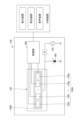
- a steering wheel sensor 102 (an example of a “sensor device”) and a steering wheel 100 (an example of a “steering wheel”) will be described with reference to FIGS. 1A to 1D.
- the steering wheel 100 in Embodiment 1 includes a rim 110, a hub 115 connected to the inside of the rim 110, connected to a rotation shaft (not shown), and positioned at the center of the steering wheel 100. , spokes 120 connecting hub 115 and rim 110 , and steering wheel sensor 102 provided on spokes 120 .
- 1A and 1B show the steering wheel 100 in a neutral state.
- the neutral state is a state in which the steering wheel 100 is not steered, and means the position of the steering wheel 100 in a state in which the vehicle is traveling straight.
- the steering wheel sensor 102 includes a capacitive sensor 130 capable of capacitive coupling with an object to be detected such as a human hand (hereinafter referred to as an operating body), a control unit 160 (an example of a “determining unit”), and a voltage circuit. and a protection circuit.
- a capacitive sensor 130 capable of capacitive coupling with an object to be detected such as a human hand (hereinafter referred to as an operating body)
- a control unit 160 an example of a “determining unit”
- a voltage circuit such as a human hand
- Steering wheel sensor 102 may not include control unit 160 , and control unit 160 may be provided outside steering wheel sensor 102 .
- the capacitive sensors 130 are provided along the edges 121a, 121b, 121c of the spokes 120 facing the inner peripheral surface of the rim 110.
- the capacitive sensor 130 has a sensor electrode and a shield electrode.
- the sensor electrode is an electrode capable of detecting electrostatic capacitance between the operating body and the shield electrode
- the shield electrode is an electrode used to suppress coupling between the sensor electrode and stray capacitance.
- a voltage circuit is connected to the shield electrode and outputs an AC voltage having a predetermined phase and a predetermined voltage.
- the protection circuit has a first end connected to the connection between the voltage circuit and the shield electrode, and a second end connected to the ground. Details of the configurations of the capacitive sensor 130, the voltage circuit, and the protection circuit will be described later with reference to FIGS. 2 to 4. FIG.
- a heater 140 for heating and warming the rim 110 is built into the rim 110 . That is, the capacitive sensor 130 and the heater 140 are provided in different parts of the steering wheel 100. FIG.
- the controller 160 is electrically connected to the capacitive sensor 130.
- the output signal of capacitive sensor 130 represents the capacitance of capacitive sensor 130 .
- the control unit 160 generates a detection signal based on changes in the capacitance of the capacitance sensor 130, and further compares the detection signal with a preset threshold to determine whether the driver's hand is on the steering wheel. , and outputs a signal representing the determination result to an external device.
- Voltage circuit 170 and Zener diode 180 are also shown in FIG. 1D. Voltage circuit 170 and Zener diode 180 will be described later with reference to FIG. 2A.
- the external device determines that the driver is not holding the steering wheel and alerts the driver.
- An external device may be in charge of the operation of the determination unit that determines whether or not the driver's hand is approaching the steering wheel.
- the control unit 160 may perform coding processing for the detection signal to facilitate communication and transmit the detection signal to the external device.
- the capacitive sensor 130 is arranged away from the heater 140 , so that the tendency of change in the capacitance of the capacitive sensor 130 changes with the capacitance of the heater 140 . almost no chance of being affected by Further, the detection signal generated by the control unit 160 based on the change in the capacitance of the capacitance sensor 130 is less likely to be affected by the capacitance of the heater 140 . In addition, since there is almost no possibility that the heat from the heater 140 will be transferred to the capacitive sensor 130, the control unit 160 can accurately detect the contact or proximity of the human hand to the steering wheel without being affected by the heater 140. It is possible to detect whether or not Also, the heater 140 can efficiently heat the rim 110 without being affected by the heat capacity of the capacitive sensor 130 .
- the control unit 160 can detect whether or not an operating object having a capacitance value, such as a human hand, is in contact with or comes close to it, based on a change in the capacitance of the capacitance sensor 130.
- the value of the capacitance of the capacitive sensor 130 depends on the distance between the capacitive sensor 130 and the operating body to be detected. becomes smaller as it moves away.
- the control unit 160 can adjust the detection range by adjusting the threshold to be compared with the value of the detection signal from the capacitive sensor 130 or by performing determination using a plurality of thresholds. It is possible. Specifically, the control unit 160 uses the part (130a, 130b) constituting the capacitive sensor 130 shown in FIG.
- the capacitive sensor 130 is built into the steering wheel sensor 102, and the steering wheel sensor 102 is covered on the driver's side with an exterior panel 125 shown in FIG. 1C.
- the capacitive sensor 130 is made of a conductor such as a conductor pattern, and is provided along the edge of the spoke 120 .
- Capacitive sensor 130 is provided at a position of spoke 120 facing the inner peripheral side of rim 110 .
- the detection areas 150a, 150b, 150c extend along a planar direction including the rim 110 as shown in FIG. 1B.
- connection portions 120a, 120b, 120c between the inner side of the rim 110 and the spokes 120, as shown in FIG. 1A.
- connection portions 120a, 120b, 120c between the inner side of the rim 110 and the spokes 120, as shown in FIG. 1A.
- the sensor electrode 130A of the steering wheel sensor 102 has a portion 130a provided along the edge 121a of the spoke 120 facing the rim 110. It also has a portion 130 b provided along the edge 121 b of the spoke 120 facing the rim 110 . Also, along the edge 121c of the spoke 120 facing the rim 110, there are partially provided portions 130c and 130d. Spoke 120 also has a portion 130e provided at connection portion 120a where spoke 120 is connected to rim 110, and a portion 130f provided along connection portion 120b.
- connection portion 120a where the spoke 120 is connected to the rim 110 is provided with a portion 130e of the sensor electrode 130A along the connection portion 120a, and the connection portion 120b is provided along the connection portion 120b.
- a portion 130f of the sensor electrode 130A is provided, and a portion 130g of the sensor electrode 130A is provided in the connecting portion 120c along the connecting portion 120c.
- a shield electrode 130B is provided to surround the portions 130a-130g.
- capacitive sensor 130 includes substrate 10, portions 130a to 130g provided on the surface of substrate 10 and functioning as sensor electrodes, and shields provided to surround portions 130a to 130g.
- 130c, 130f, 130a, 130e, 130b, 130g, and 130d are arranged in this order, edge portions 121a to 121c of the spoke 120, connection portions 120a to 120c.
- the seven portions 130a to 130g are formed, but a portion corresponding to the portion 130e, the portion 130a, the portion 130f, and the portion 130c, and the other portion of the portion 130e, the portion 130b. , 130g, and 130d, or any other number.
- the portions 130a to 130g are divided in the longitudinal direction along the edge of the spoke 120, but at the same time as being formed along the edge of the spoke 120, they are divided into two in the lateral direction (the paper surface direction of FIG. 1A). It may be divided into multiple parts. That is, the capacitive sensor 130 includes edge portions (121a, 121b) and connection portions (120a, 120b, 120c), and is continuously provided along the outer circumference of the spoke.
- the steering wheel 100 approaches the portion 130a of the capacitive sensor 130 and enters the detection area 150a. can be detected.
- the lower portion 110b of the rim 110 is grasped by a human hand, it approaches the portion 130b of the capacitive sensor 130 and enters the detection area 150b, so that the human hand can be detected. can.
- connection portion of the spokes 120 with the rim 110 or the vicinity thereof is touched and operated.
- a human hand touches the connection portion 120a of the spoke 120 or its vicinity the human hand that approaches the portion 130e of the capacitive sensor 130 enters the detection area 150a or the detection area 150b. Therefore, it is detected by the control unit 160 .
- the control unit 160 detects whether a human hand touches the connecting portion 120b of the spoke 120 or its vicinity.
- the human hand approaches the portions 130f and 130c of the capacitive sensor 130 and enters the detection area 150c.
- the control unit 160 detects whether a human hand touches the connection portion 120c of the spoke 120 or its vicinity.
- the human hand approaches the portions 130g, 130d, etc. of the capacitive sensor 130 and enters the detection area 150d. detected by unit 160 .
- a capacitive sensor may also be provided along the upper edge of the hub 115 facing the inner peripheral surface of the rim 110 and between the portion 130c and the portion 130d of the capacitive sensor 130. good. In this case, it is possible to detect that the human hand is touching the upper edge of hub 115 facing the inner peripheral surface of rim 110 and the upper side of rim 110 as well.
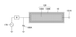
- FIG. 2A is a diagram showing the configuration of the steering wheel sensor 102 including the capacitive sensor 130. As shown in FIG. Steering wheel sensor 102 includes capacitive sensor 130 , resistor R, control section 160 , voltage circuit 170 and Zener diode 180 .
- the capacitive sensor 130 has a substrate 10 (an example of a "base material"), a sensor electrode 130A, and a shield electrode 130B.
- the longitudinal direction of capacitive sensor 130 in FIG. 2A is the direction in which portions 130c, 130f, 130a, 130e, 130b, 130g, and 130d extend in FIGS. 1A-1C.
- the lateral direction (horizontal direction in FIG. 2A) is the paper surface direction of FIGS. 1A and 1B.
- the portions 130c, 130f, 130a, 130e, 130b, 130g, and 130d are collectively shown as a sensor electrode 130A for easy understanding of the configuration.
- the substrate 10 is a plate-like wiring substrate, and for example, a flexible substrate made of polyimide or the like can be used.
- a sensor electrode 130A and a shield electrode 130B are formed on one surface of the substrate 10 .
- a planar view of the substrate 10 in a planarly extended state as shown in FIG. 2A before the substrate 10 is attached to the spokes 120 is referred to as a planar view.
- the substrate 10 actually has a rectangular shape that is very long in the longitudinal direction in plan view. In FIG. 2A, the substrate 10 is shown shortened in the longitudinal direction.
- the sensor electrode 130A is an electrode having a plurality of rectangular portions 130a to 130g formed on one surface of the substrate 10 between one end and the other end in the longitudinal direction of the substrate 10 in plan view.
- the shield electrode 130B is a rectangular annular electrode formed on one surface of the substrate 10 so as to surround the outer edge of the sensor electrode 130A.
- the shield electrode 130B surrounds the sensor electrode 130A in plan view, and is formed in the vicinity of the sensor electrode 130A along the outer edge of the sensor electrode 130A.
- the shield electrode 130B may be further provided on the surface opposite to the surface on which the sensor electrode 130A is formed on the substrate 10 .
- the sensor electrode 130A and the shield electrode 130B are capacitively coupled.
- Such sensor electrode 130A and shield electrode 130B can be realized by, for example, a thin metal layer made of metal.
- the sensor electrode 130A and the shield electrode 130B can be made of metal such as copper or aluminum, for example.
- the sensor electrode 130A has a terminal 131A.
- 130 A of sensor electrodes are connected to the control part 160 via 131 A of terminals.
- the portions 130a, 130e, and 130b of the sensor electrode 130A are not shown in FIG. 1D, actually the respective portions 130a to 130g of the sensor electrode 130A are connected to the control section 160 via the terminal 131A.
- Shield electrode 130B is connected to voltage circuit 170 via resistor R. Resistor R allows the voltage at the junction of shield electrode 130B and voltage circuit 170 to exceed the reverse breakdown voltage of Zener diode 180 when a statically charged hand touches spoke 120.
- the voltage circuit 170 outputs an AC voltage having a predetermined frequency, a predetermined phase, and a predetermined voltage, and the AC voltage is applied to the shield electrode 130B. Since the sensor electrode 130A is capacitively coupled with the shield electrode 130B, an AC voltage is applied to the sensor electrode 130A via the shield electrode 130B. An AC voltage having the same frequency, phase, and amplitude as the AC voltage applied to the shield electrode 130B is applied to the sensor electrode 130A.
- the voltage circuit 170 is connected to both the sensor electrode 130A and the shield electrode 130B, and AC voltages having the same frequency, the same phase, and the same amplitude are applied from the voltage circuit 170 to both the sensor electrode 130A and the shield electrode 130B. good too.
- the amplitude of the AC voltage applied to the sensor electrode 130A may be different from the amplitude of the AC voltage applied to the shield electrode 130B as long as the effect of the active shield is not impaired.
- a cathode (an example of a "first end") of a Zener diode 180 is connected to the connection between the shield electrode 130B and the voltage circuit 170.
- the anode (an example of a “second end”) of Zener diode 180 is connected to ground.
- a Zener diode 180 is provided as a protection circuit.
- the shield electrode 130B When the voltage of the shield electrode 130B (positive AC voltage) is less than the reverse breakdown voltage (Zener voltage) of the Zener diode 180, no reverse current (Zener current) flows through the Zener diode 180, and the shield electrode 130B functions as an active shield.
- FIG. 2B is a diagram showing a sensor device 50 for comparison.
- the comparative sensor device 50 shown in FIG. 2B was made for comparison rather than prior art.
- the substrate 10 is of the same type and size as the steering wheel sensor 102 (sensor device) of the first embodiment.
- the sensor device 50 for comparison has a ground electrode 51 provided on one surface of the substrate 10 in addition to the capacitive sensor 13 (the sensor electrode 13A and the shield electrode 13B), and the Zener diode 180 is eliminated. It is different from the steering wheel sensor 102 (sensor device) of form 1.
- the capacitive sensor 13 having the sensor electrode 13A and the shield electrode 13B is obtained by making the sensor electrode 130A and the shield electrode 130B of the capacitive sensor 130 of the steering wheel sensor 102 (sensor device) of the first embodiment smaller in plane. have a configuration.
- a rectangular annular ground electrode 51 is provided outside the shield electrode 13B. The ground electrode 51 is connected to the ground.
- the rectangular ring-shaped ground electrode 51 is provided outside the shield electrode 13B of the capacitive sensor 13, when using the substrate 10 of the same size, the steering wheel sensor 102 (sensor device ), the capacitive sensor 13 becomes smaller.
- the area of the sensor electrode 130A can be made larger than the sensor electrode 13A of the sensor device 50 for comparison. Therefore, the sensitivity gain of the sensor electrode 130A can be sufficiently increased. In addition, good S/N characteristics can be obtained without generating unnecessary capacitance in the sensor electrode 130A. In addition, the S/N characteristic is improved by suppressing the decrease in the electric line of force generated in the sensor electrode 130A. In addition, by increasing the area of the sensor electrode 130A (widening), an effect of improving the S/N characteristic can be obtained.
- the size of the entire capacitive sensor 130 can be reduced by the amount that does not include the ground electrode 51 of the sensor device 50 for comparison.
- an active shield can be realized with the shield electrode 130B.
- the Zener diode 180 is included, the cathode of which is connected to the connection between the shield electrode 130B and the voltage circuit 170, and the anode of which is connected to the ground, even if a momentary large current is generated due to static electricity or the like, the Zener diode 180 is can be reversed to allow current to flow to ground.
- the steering wheel sensor 102 (sensor device) capable of suppressing the influence of the stray capacitance on the detected value of the sensor electrode 130A and the damage of the voltage circuit 170 and the control section 160 due to static electricity.
- the sensor electrode 130A can be made larger, so that a good S/N characteristic can be obtained.
- the shield electrode 130B surrounds the sensor electrode 130A, even if static electricity is generated at any position around the sensor electrode 130A, the shield electrode 130B can absorb the static electricity and prevent the static electricity from flying to the sensor electrode 130A. can be suppressed. That is, effective ESD (Electro-Static Discharge) countermeasures can be applied to the sensor electrode 130A.
- ESD Electro-Static Discharge
- the voltage circuit 170 is connected to the sensor electrode 130A, and the sensor electrode 130A is supplied with an AC voltage having the same phase as that of the shield electrode 130B. Capacitance can be accurately detected.
- the sensor electrode 130A is supplied with an AC voltage having the same voltage (same amplitude) as that of the shield electrode 130B, the influence of the ground is eliminated, and the capacitance between the operating body and the sensor electrode 130A can be determined more accurately. can be detected.
- the sensor electrode 130A and the shield electrode 130B are provided along the edges 121a, 121b, 121c of the spokes 120 facing the rim 110 of the steering wheel 100 having the rim 110, the spokes 120, and the hub 115, It can be determined whether the person's hand is placed in a position where the steering wheel 100 can be readily operated. Moreover, even in the configuration in which the heater 140 is built in the rim 110, it is possible to determine whether or not the driver's hands are placed in a position where the steering wheel 100 can be operated immediately.
- FIG. 3 is a diagram showing the configuration of the spoke 120 portion of the steering wheel 100 of the first modified example of the first embodiment and its surroundings.
- FIG. 3 shows, as an example, the spoke 120 located on the right side of the steering wheel 100 in the neutral state.
- the rim 110 and hub 115 are omitted.
- the spoke 120 is provided with a housing portion 124 for housing the steering switch 185 and a notch 124A.
- the accommodation portion 124 is a concave portion.
- the notch 124A communicates with the hub 115 side (the center side of the steering wheel 100) end of the accommodating portion 124, and extends in the extending direction of the spoke 120 (the radial direction of the steering wheel 100) on the back side of the spoke 120.
- the groove is provided in a direction substantially perpendicular to the steering wheel 100 (the vertical direction when the steering wheel 100 is attached to the vehicle).
- the cutouts 124A are provided above and below the hub 115 side end of the accommodating portion 124 .
- the steering switch 185 has a housing 185A and an operation section 185B.
- the housing 185A is a case made of resin, and has an extension direction of the capacitive sensor 130 (the sensor electrode 130A and the shield electrode 130B) on the side surface (the direction in which sections A and B in FIG. 4 described later extend).
- the spoke 120 is fitted into the accommodating portion 124 from the rear side (lower side in FIG. 3) with the central portion (section A in FIG. 4 described later) attached. At this time, the portion outside the central portion of the capacitive sensor 130 in the extending direction (section B in FIG. 4, which will be described later) is passed through the notch 124A.
- the operation unit 185B is an operation unit realized by a dial type switch, button switch, or the like.
- FIG. 4 is a diagram showing the capacitive sensor 130.
- Capacitive sensor 130 is attached to housing 185A by attaching substrate 10 to the side surface of housing 185A. More specifically, the section A portion of the capacitive sensor 130 is attached to the side surface of the housing 185A (three side surfaces as an example in FIG. 3) as shown in FIG. It is not attached to the side surface of body 185A.
- the sensor electrode 130A and the shield electrode 130B are positioned inside the rim 110. Face the circumference. At this time, of the two sections B located on both end sides in the extending direction of the capacitive sensor 130, the portion adjacent to the section A is inserted into the notch 124A. In this manner, the sensor electrode 130A and the shield electrode 130B are provided on the housing 185A of the steering switch 185 so as to face the inner peripheral side of the rim 110 when the steering switch 185 is housed in the housing portion 124.
- the horizontal direction is the extending direction of the sensor electrode 130A
- the width of the sensor electrode 130A is the vertical direction in FIG.
- the width of the shield electrode 130B is the width in the vertical direction perpendicular to the direction extending along the sensor electrode 130A (horizontal direction in FIG. 4).
- the sensor electrode 130A has a narrowed width portion 132A in the section A where the steering switch 185 is present.
- the shield electrode 130B has a widened portion 132B in the section A where the steering switch 185 is present. Since the sensor electrode 130A has the narrowed width portion 132A and the shield electrode 130B has the widened portion 132B, the width of the shield electrode 130B with respect to the width of the sensor electrode 130A is larger than that of the section B where the steering switch does not exist. , the section A in which the steering switch is present is wider.
- a steering wheel sensor 102 (sensor device) can be provided.
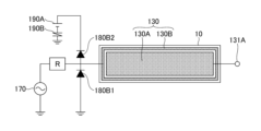
- FIG. 5A is a diagram showing the configuration of the capacitive sensor 130 of the second modification of the first embodiment.
- the capacitive sensor 130 of the second modification of the first embodiment has a configuration using a varistor 180A instead of the Zener diode 180 in FIG. 2A.
- FIG. 5B is a diagram showing the configuration of the capacitive sensor 130 of the third modification of the first embodiment.
- the capacitive sensor 130 of the third modification of the first embodiment has a configuration using diodes 180B1 and 180B2 instead of the Zener diode 180 in FIG. 2A.
- Diodes 180B1 and 180B2 are an example of a protection circuit.
- the diode 180B1 has its anode connected to the ground and its cathode connected to the connection between the shield electrode 130B and the voltage circuit 170, like the Zener diode 180 in FIG. 2A.
- the first end of diode 180B1 as a protection circuit is the cathode and the second end is the anode.
- the diode 180B2 has an anode connected to the connection between the shield electrode 130B and the voltage circuit 170, and a cathode connected to the positive terminal of the DC power supply 190A.
- a negative terminal of the DC power supply 190A is connected to ground via a varistor 190B.
- the first end of the protection circuit diode 180B2 is the anode and the second end is the cathode.
- the voltage difference between the voltage of the shield electrode 130B (the negative voltage of the AC voltage) and the voltage of the ground (0 V) is less than the forward voltage of the diode 180B1, and the voltage of the positive terminal of the DC power supply 190A from the voltage of the shield electrode 130B. is less than the forward voltage of diode 180B2, no forward current flows through diode 180B1 and no forward current flows through diode 180B2. In this state, shield electrode 130B functions as an active shield.
- FIG. 6A is a diagram showing a PC (Personal Computer) 200 including the sensor device of the second embodiment.
- PC 200 has a housing 210 and a touch pad 220 .
- Housing 210 has an opening 211 that exposes touchpad 220 .
- FIG. 6B is a diagram showing the sensor device 200A of Embodiment 2.
- the sensor device 200A includes a sensor electrode 130A, a shield electrode 130B, a control section 160, a resistor R, a voltage circuit 170, and a Zener diode 180.
- the capacitive sensor 130 of the sensor device 200A is provided on the back side of the cover of the touch pad 220. As shown in FIG. 6B, the capacitive sensor 130 of the sensor device 200A has sensor electrodes 130A and shield electrodes 130B corresponding to the size of the touch pad 220 (FIG. 6A). The sensor electrode 130A and the shield electrode 130B are provided inside the housing 210 (see FIG. 6A), and as shown in FIG. .
- the Zener diode 180 When the touch pad 220 is operated and the voltage of the shield electrode 130B (positive AC voltage) is less than the reverse breakdown voltage (Zener voltage) of the Zener diode 180, the Zener diode 180 receives a reverse current ( Zener current) does not flow, and the shield electrode 130B functions as an active shield.
- a statically charged hand touches the touch pad 220, and the voltage at the connection between the shield electrode 130B and the voltage circuit 170 is equal to or higher than the breakdown voltage of the Zener diode 180 in the reverse direction. Then, a reverse current flows through the Zener diode 180, and a large current instantaneously generated by static electricity flows toward the ground.
- the shield electrode 130B is arranged inside the opening edge of the opening 211 in a plan view, even if static electricity enters the interior through the gap between the opening edge of the opening 211, the Zener diode 180 is removed from the shield electrode 130B. Since a momentary large current due to static electricity can flow toward the ground through the ground, damage to the voltage circuit 170 and the control unit 160 can be effectively suppressed. Moreover, since the shield electrode 130B functions as an active shield, it is possible to reduce the influence of floating capacitance on the detection value of the sensor electrode 130A.
- the sensor device 200A provided in the touch pad 220 and capable of suppressing the influence of the stray capacitance on the detection value of the sensor electrode 130A and the damage of the voltage circuit 170 and the control section 160 due to static electricity.
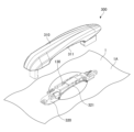
- FIG. 7A is a diagram showing a door handle (an example of a handle) 300 to which the sensor device of Embodiment 3 is applied.
- a door handle case which is a housing portion of the door handle 300, includes an outer case 310 and an inner case 320, and a capacitive sensor 130 is provided inside the case covered with the outer case 310 and the inner case 320.
- the inner case 320 is an example of a first insulating case attached to the vehicle body 1 along the exterior surface 1A of the vehicle body 1
- the outer case 310 is an insulating first case attached to the inner case 320 (first case). This is an example of case 2.
- FIG. 7B is a diagram showing the sensor device 300A of Embodiment 3.
- Sensor device 300A includes sensor electrode 130A, shield electrode 130B, controller 160, resistor R, voltage circuit 170, and Zener diode 180.
- the capacitive sensor 130 of the sensor device 300A is provided inside the door handle 300.
- capacitive sensor 130 of sensor device 300A has sensor electrode 130A and shield electrode 130B corresponding to the size of door handle 300 (FIG. 7A).
- the shield electrode 130B is provided along the seam between the outer case 310 and the inner case 320 of the door handle 300.
- the joint between the outer case 310 and the inner case 320 is a portion where the edge 311 of the inner case 320 of the outer case 310 and the edge 321 of the inner case 320 on the outer case 310 side are aligned.
- At least part of the shield electrode 130 ⁇ /b>B may be provided along the seam between the outer case 310 and the inner case 320 of the door handle 300 .
- the shield electrode 130B When the door handle 300 is operated and the voltage of the shield electrode 130B (positive AC voltage) is less than the reverse breakdown voltage (Zener voltage) of the Zener diode 180, a reverse current ( Zener current) does not flow, and the shield electrode 130B functions as an active shield.
- a statically charged hand touches the door handle 300, and the voltage at the connection between the shield electrode 130B and the voltage circuit 170 rises above the breakdown voltage of the Zener diode 180 in the reverse direction. Then, a reverse current flows through the Zener diode 180, and a large current instantaneously generated by static electricity flows toward the ground.
- the shield electrode 130B is arranged along the seam between the outer case 310 and the inner case 320, even if static electricity enters through the gap between the outer case 310 and the inner case 320, the shield electrode 130B Since a momentary large current due to static electricity can flow toward the ground through the Zener diode 180, damage to the voltage circuit 170 and the control unit 160 can be effectively suppressed. Moreover, since the shield electrode 130B functions as an active shield, it is possible to reduce the influence of floating capacitance on the detection value of the sensor electrode 130A.
- the sensor device 300A provided in the door handle 300 and capable of suppressing the influence of the stray capacitance on the detection value of the sensor electrode 130A and the damage of the voltage circuit 170 and the control section 160 due to static electricity.
- Vehicle body 1A Exterior surface 10 Substrate 100 Steering wheel 102 Steering wheel sensor 110 Rim 115 Hub 120 Spoke 124 Housing part 130 Capacitive sensor 130A Sensor electrode 130B Shield electrode 132A Narrowed width part 132B Widened part 160 Control part ("determining part" example) 170 voltage circuit 180 Zener diode (an example of a protection circuit) 180A varistor (an example of a protection circuit) 180B1 diode (an example of a protection circuit) 180B2 diode (an example of a protection circuit) 185 steering switch 185A housing 190A DC power supply 200A sensor device 210 housing 211 opening 220 touch pad 300 door handle 300A sensor device 310 outer case (an example of the second case) 320 inner case (an example of the first case)
Landscapes
- Engineering & Computer Science (AREA)
- Chemical & Material Sciences (AREA)
- Combustion & Propulsion (AREA)
- Transportation (AREA)
- Mechanical Engineering (AREA)
- Switches That Are Operated By Magnetic Or Electric Fields (AREA)
Abstract
センサ電極の検出値における浮遊容量の影響と、静電気によるダメージとを抑制可能なセンサ装置を提供する。 センサ装置は、板状の基材に設けられるセンサ電極と、前記センサ電極の外縁を囲むように前記板状の基材に設けられ、前記センサ電極と容量結合するシールド電極と、前記シールド電極に接続され、所定位相及び所定電圧の交流電圧を出力する電圧回路と、前記センサ電極に接続され、前記センサ電極の出力信号に基づいて操作体の近接又は接触を判定する判定部と、前記電圧回路と前記シールド電極との接続部に接続される第1端部と、グランドに接続される第2端部とを有する保護回路とを含む。
Description
本開示は、センサ装置に関する。
従来より、ステアリングホイールに内蔵された静電容量式のセンサ装置であって、前記ステアリングホイールは、リムと前記リムの内側に接続されたスポークとを有し、前記センサ装置は、検出するべき物体と容量結合が可能な電極と、制御部とを含み、前記スポーク上に設けられており、前記制御部は、前記リムまたは前記スポークに物体が近接した際に発生する前記電極の静電容量の変化を検出し、前記静電容量の変化に基づいて物体が近接したか否かについて判定することを特徴とするセンサ装置がある(例えば、特許文献1参照)。
また、静電容量の変化に基づいて物体が近接したか否かについて判定するセンサ装置を、タッチパッド或いはドアハンドルへの接近を検知するセンサとして用いる技術も公知である(例えば、特許文献2,3参照)。
ところで、従来のセンサ装置は、導線等で静電容量センサを形成し、スポークの縁部に設ける構成であり、浮遊容量による影響があった。また、人が接触するスポークにセンサ電極が配置されているため、静電気によってセンサ電極にダメージを与えないよう電極が露出しないよう配置する必要があり、構造が複雑になるという問題があった。
そこで、センサ電極の検出値における浮遊容量の影響と、静電気によるダメージとを抑制可能なセンサ装置を提供することを目的とする。
本開示の実施形態のセンサ装置は、基材に設けられるセンサ電極と、前記センサ電極の外縁を囲むように前記板状の基材に設けられ、前記センサ電極と容量結合するシールド電極と、前記シールド電極に接続され、所定位相及び所定電圧の交流電圧を出力する電圧回路と、前記電圧回路と前記シールド電極との接続部に接続される第1端部と、グランドに接続される第2端部とを有する保護回路とを含む。
センサ電極の検出値における浮遊容量の影響と、静電気によるダメージとを抑制可能なセンサ装置を提供することができる。
以下、本開示のセンサ装置を適用した実施形態について説明する。
<実施形態1>
ステアリングホイールセンサ102(「センサ装置」の一例)及びステアリングホイール100(「ステアリングホイール」の一例)について図1A~図1Dに基づき説明する。実施形態1におけるステアリングホイール100は、図1Aに示されるように、リム110と、リム110の内側に接続され、不図示の回転軸と接続されていてステアリングホイール100の中心に位置するハブ115と、ハブ115とリム110を接続するスポーク120と、スポーク120上に設けられたステアリングホイールセンサ102とを有している。なお、図1A及び図1Bには、中立状態のステアリングホイール100を示す。中立状態とは、ステアリングホイール100を操舵していない状態であり、車両が直進する状態のステアリングホイール100の位置を意味する。
ステアリングホイールセンサ102(「センサ装置」の一例)及びステアリングホイール100(「ステアリングホイール」の一例)について図1A~図1Dに基づき説明する。実施形態1におけるステアリングホイール100は、図1Aに示されるように、リム110と、リム110の内側に接続され、不図示の回転軸と接続されていてステアリングホイール100の中心に位置するハブ115と、ハブ115とリム110を接続するスポーク120と、スポーク120上に設けられたステアリングホイールセンサ102とを有している。なお、図1A及び図1Bには、中立状態のステアリングホイール100を示す。中立状態とは、ステアリングホイール100を操舵していない状態であり、車両が直進する状態のステアリングホイール100の位置を意味する。
ステアリングホイールセンサ102は、人の手等の検出するべき物体(以下、操作体)と容量結合が可能な静電容量式センサ130と、制御部160(「判定部」の一例)と、電圧回路と、保護回路とを有している。なお、ステアリングホイールセンサ102は、制御部160を含まなくてもよく、制御部160は、ステアリングホイールセンサ102の外部に設けられていてもよい。
静電容量式センサ130は、リム110の内周面と対向するスポーク120の縁部121a、121b、121cに沿って設けられている。静電容量式センサ130は、センサ電極とシールド電極とを有する。センサ電極は、操作体との間の静電容量を検出可能な電極であり、シールド電極は、センサ電極と浮遊容量との結合を抑制するために用いられる電極である。電圧回路は、シールド電極に接続され、所定位相及び所定電圧の交流電圧を出力する。
また、保護回路は、電圧回路とシールド電極との接続部に接続される第1端部と、グランドに接続される第2端部とを有する。このような静電容量式センサ130、電圧回路、及び保護回路の構成の詳細については、図2乃至図4を用いて後述する。
リム110を加熱し温めるためのヒータ140は、リム110に内蔵されている。即ち、静電容量式センサ130とヒータ140とは、ステアリングホイール100の異なる部分に設けられている。
図1Dに示されるように、制御部160は、静電容量式センサ130と電気的に接続されている。静電容量式センサ130の出力信号は、静電容量式センサ130の静電容量を表す。制御部160は、静電容量式センサ130の静電容量の変化に基づいて検出信号を生成し、更に、その検出信号と予め設定された閾値とを比較して、運転者の手がステアリングホイールに接近しているか否かを判定し、判定結果を表す信号を外部装置に出力する。図1Dには、電圧回路170及びツェナーダイオード180も示す。電圧回路170及びツェナーダイオード180については、図2Aを用いて後述する。
外部装置は、判定結果が否であった場合には、手でステアリングを掴んでいないと判断して運転者に注意喚起を促す。尚、運転者の手がステアリングホイールに接近しているか否かを判定する判定部の動作は、外部装置が担当してもよい。この場合には、制御部160は、検出信号に対して通信で伝達し易くするためのコード化の処理を行い、外部装置に検出信号を送信すればよい。
このように、ステアリングホイール100は、静電容量式センサ130がヒータ140から離れて配置されていることによって、静電容量式センサ130の静電容量の変化の傾向は、ヒータ140の静電容量に影響を受ける可能性はほぼ無くなる。また、静電容量式センサ130の静電容量の変化に基づいて制御部160で生成される検出信号は、ヒータ140の静電容量に影響を受ける可能性はほぼ無くなる。また、ヒータ140からの熱が静電容量式センサ130へ伝達される可能性はほぼ無くなるため、制御部160は、ヒータ140による影響を受けることなく正確に人の手がステアリングホイールに接触または近接したか否かを検出することができる。また、ヒータ140は静電容量式センサ130の熱容量に影響を受けることなくリム110を効率よく温めることができる。
ところで、制御部160は、静電容量式センサ130の静電容量の変化により人の手を始めとした容量値を有した操作体が接触または近接したか否かを検出することができるが、静電容量式センサ130の静電容量の値は、静電容量式センサ130と検出対象となる操作体との間の距離に依存するため、静電容量式センサ130に操作体が近づくと大きくなり、離れると小さくなる。このことを利用して、静電容量式センサ130からの検出信号の値と比較する閾値を調節または複数の閾値を用いて判定を行うことにより、制御部160は、検出範囲を調節することが可能である。具体的には、制御部160は、図1Aに示される静電容量式センサ130を構成する部分(130a、130b)のうち、リム110からの距離がもっとも遠い部位を用いた場合であっても、リム110に操作体が近接したことを判定することが可能である。そのため、例えば、図1Bに示されるリム110とリム110の内周面と対向するスポーク120の縁部121a、121b、121cに沿って設けられた静電容量式センサ130との間、および、リム110の周囲に設定された検出領域150a、150b、150cに操作体が存在していたときはそのことが制御部160で判定される。
尚、実施形態1において、静電容量式センサ130は、ステアリングホイールセンサ102に内蔵されており、ステアリングホイールセンサ102は、図1Cに示される外観パネル125により運転者側が覆われている。静電容量式センサ130は、導体パターン等の導電体により形成されており、スポーク120の縁部に沿って設けられている。静電容量式センサ130は、スポーク120のうちのリム110の内周側を向く位置に設けられる。検出領域150a、150b、150cは、図1Bに示すようにリム110を含む平面方向に沿って広がっている。
更に、前述のリム110とスポーク120とは、具体的には、図1Aに示すように、リム110の内側と、スポーク120との接続部120a、120b、120cにおいて接続されている。また、スポーク120の外周縁に沿って静電容量式センサ130の厚さより若干大きい溝が設けられていて静電容量式センサ130を図1Aに示すよう保持しているが、スポーク120のリム110と対向する外表面に保持しても良い。
ステアリングホイールセンサ102のセンサ電極130Aは、リム110と対向するスポーク120の縁部121aに沿って設けられた部分130aを有している。また、リム110と対向するスポーク120の縁部121bに沿って設けられた部分130bを有している。また、リム110と対向するスポーク120の縁部121cに沿って、部分的に設けられた部分130c、130dを有している。また、スポーク120がリム110と接続されている接続部120aに設けられた部分130eと、接続部120bに沿って設けられた部分130fを有している。
また、スポーク120がリム110と接続されている接続部120aには、接続部120aに沿って、センサ電極130Aの部分130eが設けられており、接続部120bには、接続部120bに沿って、センサ電極130Aの部分130fが設けられており、接続部120cには、接続部120cに沿って、センサ電極130Aの部分130gが設けられている。また、部分130a~130gを囲むようにシールド電極130Bが設けられている。
図1Cに示されるように、静電容量式センサ130は、基板10と、基板10の表面に設けられセンサ電極として機能する部分130a~130gと、部分130a~130gを囲むように設けられたシールド電極130B等により形成されおり、部分130c、部分130f、部分130a、部分130e、部分130b、部分130g、部分130dの順に並んで形成されていて、スポーク120の縁部121a~121c、接続部120a~120cに沿って配置される。尚、実施形態1においては、部分130a~130gの7つで形成したが、部分130eの一部、部分130a、部分130f、部分130cに対応する部分と、部分130eの他の一部、部分130b、部分130g、部分130dに対応する部分の2つの部分で形成しても良く、それ以外の数で形成しても良い。また、部分130a~130gは、スポーク120の縁部に沿って長手方向に分割されているが、スポーク120の縁部に沿って形成すると同時に短手方向(図1Aの紙面方向)に2分割等複数に分割しても良い。つまり、静電容量式センサ130は、縁部(121a、121b)と接続部(120a、120b、120c)とを含んで構成され、スポークの外周に沿って連続的に設けられている。
ステアリングホイール100は、例えば、リム110の下側の部分110aが人の手により握られた場合には、静電容量式センサ130の部分130aに近づき、検出領域150a内に入るため、人の手を検出することができる。また、リム110の下側の部分110bが人の手により握られた場合には、静電容量式センサ130の部分130bに近づき、検出領域150b内に入るため、人の手を検出することができる。
また、人が車両を運転する際には、スポーク120のリム110との接続部やその近傍に手が触れて操作する場合がある。例えば、スポーク120の接続部120aまたはその近傍に人の手が触れている場合には、静電容量式センサ130の部分130eに近づいた人の手は、検出領域150aまたは検出領域150b内に入るため、制御部160によって検出される。または、静電容量式センサ130の部分130eに近づいた人の手は、静電容量式センサ130の部分130aの接続部120a側または静電容量式センサ130の部分130bの接続部120a側に近づき、検出領域150aまたは検出領域150b内に入るため、制御部160によって検出される。
また、スポーク120の接続部120bまたはその近傍に人の手が触れている場合には、人の手は静電容量式センサ130の部分130f、部分130c等に近づき、検出領域150c内に入るため、制御部160によって検出される。スポーク120の接続部120cまたはその近傍に人の手が触れている場合には、人の手は静電容量式センサ130の部分130g、部分130d等に近づき、検出領域150d内に入るため、制御部160によって検出される。
なお、リム110の内周面と対向するハブ115の上側の縁部に沿って、静電容量式センサ130の部分130cと部分130dの間の部分にも、静電容量式センサを設けてもよい。この場合には、リム110の内周面と対向するハブ115の上側の縁部と、リム110の上側とにおいても人の手が触れていることを検出することができる。
<静電容量式センサ130の構成>
図2Aは、静電容量式センサ130を含むステアリングホイールセンサ102の構成を示す図である。ステアリングホイールセンサ102は、静電容量式センサ130、抵抗器R、制御部160、電圧回路170、及びツェナーダイオード180を含む。
図2Aは、静電容量式センサ130を含むステアリングホイールセンサ102の構成を示す図である。ステアリングホイールセンサ102は、静電容量式センサ130、抵抗器R、制御部160、電圧回路170、及びツェナーダイオード180を含む。
静電容量式センサ130は、基板10(「基材」の一例)、センサ電極130A、及びシールド電極130Bを有する。図2Aにおける静電容量式センサ130の長手方向(図2Aにおける横方向)は、図1A乃至図1Cにおいて、部分130c、130f、130a、130e、130b、130g、及び130dが延在する方向であり短手方向(図2Aにおける横方向)は、図1A,1Bの紙面方向である。また、図2Aでは、構成を分かり易くするために、部分130c、130f、130a、130e、130b、130g、及び130dをまとめてセンサ電極130Aとして示す。
基板10は、板状の配線基板であり、一例として、ポリイミド等で作製されるフレキシブル基板を用いることができる。基板10の一方の面には、センサ電極130A及びシールド電極130Bが形成されている。なお、以下では、基板10をスポーク120に取り付ける前の状態で、図2Aに示すように基板10を平面的に延ばした状態において平面視することを平面視と称す。基板10は、実際には、平面視において、長手方向に非常に長い矩形状である。図2Aでは、基板10を長手方向において短縮して示す。
センサ電極130Aは、平面視において、基板10の長手方向における一端と他端との間で、基板10の一方の表面に形成される複数の矩形状の部分130a~130gを有する電極である。シールド電極130Bは、センサ電極130Aの外縁を囲むように、基板10の一方の表面に形成される矩形環状の電極である。シールド電極130Bは、平面視でセンサ電極130Aを囲っており、センサ電極130Aの外縁に沿って、センサ電極130Aの近傍に形成されている。なお、シールド電極130Bは、センサ電極130Aが基板10に形成される表面とは反対側の表面の一面に、更に設けられていてもよい。
センサ電極130A及びシールド電極130Bは、容量結合している。このようなセンサ電極130A及びシールド電極130Bは、一例として、金属製の薄膜状の金属層で実現可能である。センサ電極130A及びシールド電極130Bは、一例として、銅又はアルミニウム等の金属で作製可能である。
センサ電極130Aは、端子131Aを有する。センサ電極130Aは、端子131Aを介して制御部160に接続される。なお図1Dではセンサ電極130Aの部分130a、130e、及び130bの図示を省略しているが、実際には、センサ電極130Aのそれぞれの部分130a~130gが端子131Aを介して制御部160に接続される。シールド電極130Bは、抵抗器Rを介して電圧回路170に接続されている。抵抗器Rは、静電気を帯びている手がスポーク120に触れたときに、シールド電極130Bと電圧回路170との接続部の電圧をツェナーダイオード180の逆方向での降伏電圧以上にすることができるようにするために設けられている。このような抵抗器Rをシールド電極130Bと電圧回路170との接続部に設けることにより、静電気を帯びている手がスポーク120に触れたときに、静電気は、手からの沿面距離がセンサ電極130Aより近いシールド電極130Bに放電し、瞬間的な大電流がシールド電極130Bから電圧電源170に流れることを抑制できると同時に、瞬間的な大電流がセンサ電極130Aから制御部160に流れることを抑制することができる。
電圧回路170は、所定周波数、所定位相、及び所定電圧の交流電圧を出力し、交流電圧はシールド電極130Bに印加される。センサ電極130Aはシールド電極130Bと容量結合されているため、センサ電極130Aにはシールド電極130Bを介して交流電圧が印加される。センサ電極130Aにはシールド電極130Bに印加される交流電圧と同一周波数、同一位相、及び同一振幅の交流電圧が印加される。
このように、センサ電極130A及びシールド電極130Bに、同一周波数、同一位相、及び同一振幅の交流電圧を印加することにより、センサ電極130Aとシールド電極130Bとの間のコンデンサに電荷が生じないため、グランドの影響が排除され、操作体とセンサ電極130Aとの間の静電容量を正確に検出することができる。このように、センサ電極130A及びシールド電極130Bに、同一周波数、同一位相、及び同一振幅の交流電圧を印加することにより、アクティブシールドを実現でき、センサ電極130Aとグランド等との間の浮遊容量の影響を排除することができる。
なお、電圧回路170をセンサ電極130A及びシールド電極130Bの両方に接続して、電圧回路170からセンサ電極130A及びシールド電極130Bの両方に同一周波数、同一位相、及び同一振幅の交流電圧を印加してもよい。
また、アクティブシールドの効果が損なわれなければ、センサ電極130Aに印加される交流電圧の振幅は、シールド電極130Bに印加される交流電圧の振幅と異なっていてもよい。
シールド電極130Bと電圧回路170との間の接続部には、ツェナーダイオード180(「保護回路」の一例)のカソード(「第1端部」の一例)が接続される。ツェナーダイオード180のアノード(「第2端部」の一例)は、グランドに接続されている。
人の手がステアリングホイール100のスポーク120に触れるときに、手が静電気を帯びていると、静電気の放電によってシールド電極130Bから電圧電源170に瞬間的に大電流が流れ、制御部160が破損するおそれがある。このような電圧電源170の破損を抑制するために、保護回路としてのツェナーダイオード180を設けている。
シールド電極130Bの電圧(交流電圧の正電圧)がツェナーダイオード180の逆方向での降伏電圧(ツェナー電圧)未満であるときには、ツェナーダイオード180には逆方向電流(ツェナー電流)は流れず、シールド電極130Bは、アクティブシールドとして機能する。
また、静電気を帯びている手がスポーク120に触れて、シールド電極130Bと電圧回路170との接続部の電圧がツェナーダイオード180の逆方向での降伏電圧以上になると、ツェナーダイオード180に逆方向電流が流れ、静電気によって瞬間的に生じる大電流をグランドに向けて流す。このため、シールド電極130Bから電圧回路170に向かって瞬間的に大電流が流れることを抑制でき、電圧回路170の破損を抑制することができる。同時に、シールド電極130Bをセンサ電極130Aの周囲に配置していて、手とセンサ電極130Aの間の空間にシールド電極130Bが存在することとなるので、静電気がセンサ電極130Aに放電する事もなく、よってセンサ電極130Aに繋がる制御部160の破損を抑制する事ができる。
<比較用のセンサ装置50>
図2Bは、比較用のセンサ装置50を示す図である。図2Bに示す比較用のセンサ装置50は、従来技術ではなく、比較用に作製したものである。
図2Bは、比較用のセンサ装置50を示す図である。図2Bに示す比較用のセンサ装置50は、従来技術ではなく、比較用に作製したものである。
図2Bに示す比較用のセンサ装置50は、基板10、静電容量式センサ13(センサ電極13A及びシールド電極13B)、グランド電極51、抵抗器R、及び電圧回路170を含む。基板10は、実施形態1のステアリングホイールセンサ102(センサ装置)と同一サイズの同一種類の基板である。
比較用のセンサ装置50は、基板10の一方の表面に、静電容量式センサ13(センサ電極13A及びシールド電極13B)の他にグランド電極51を設けるとともに、ツェナーダイオード180を排除した点が実施形態1のステアリングホイールセンサ102(センサ装置)と異なる。センサ電極13A及びシールド電極13Bを有する静電容量式センサ13は、実施形態1のステアリングホイールセンサ102(センサ装置)の静電容量式センサ130のセンサ電極130A及びシールド電極130Bを平面的に小さくした構成を有する。シールド電極13Bの外側には、矩形環状のグランド電極51を設けられている。グランド電極51は、グランドに接続されている。
このような比較用のセンサ装置50では、静電気を帯びている手が近づくと、静電気によって瞬間的に生じる大電流は、グランド電極51を通じてグランドに向かって流れる。このため、センサ電極13Aから制御部160に向かって瞬間的に大電流が流れることを抑制でき、制御部160の破損を抑制することができる。
しかしながら、静電容量式センサ13のシールド電極13Bの外側に、矩形環状のグランド電極51を設けているため、同一サイズの基板10を用いる場合には、実施形態1のステアリングホイールセンサ102(センサ装置)の静電容量式センサ130に比べると、静電容量式センサ13が小さくなる。
このため、センサ電極13Aと手との間の十分な静電容量が得られず、センサ電極13Aの感度ゲインを十分に上げられないという問題や、グランド電極51とセンサ電極13A及びシールド電極13Bとの間に不要な容量が増える分だけノイズ成分が増えてS/N(シグナル/ノイズ比)特性が悪くなるという問題が生じる。また、センサ電極13Aに生じる電気力線が近傍のグランド電極51に引き寄せられ、センサ電極13Aと手との間の電気力線が減少することによってもS/N特性が悪くなるという問題や、グランド電極51を配置することによって、静電容量式センサ13(センサ電極13A及びシールド電極13B)の面積が狭くなることによってS/N特性が小さくなるという問題が生じる。
これに対して、実施形態1のステアリングホイールセンサ102(センサ装置)では、比較用のセンサ装置50のセンサ電極13Aに比べて、センサ電極130Aの面積を大きくできる。このため、センサ電極130Aの感度ゲインを十分に上げることができる。また、センサ電極130Aに不要な容量が生じることがなく良好なS/N特性が得られる。また、センサ電極130Aに生じる電気力線の減少を抑制できることでS/N特性が良好になる。また、センサ電極130Aの面積が大きく(広く)なることによってS/N特性が良好になるという効果が得られる。
また、比較用のセンサ装置50のグランド電極51を含まない分だけ静電容量式センサ130の全体を小形化することができる。
以上のように、シールド電極130Bでアクティブシールドを実現できる。また、シールド電極130Bと電圧回路170との接続部にカソードが接続され、アノードがグランドに接続されるツェナーダイオード180を含むので、静電気等で瞬間的な大電流が発生しても、ツェナーダイオード180を逆流させてグランドに電流を流すことができる。
したがって、センサ電極130Aの検出値における浮遊容量の影響と、静電気による電圧回路170及び制御部160のダメージとを抑制可能なステアリングホイールセンサ102(センサ装置)を提供することができる。
また、図2Bに示す比較用のセンサ装置50のように、シールド電極13Bの周囲にグランド電極51を有する構成と比べると、グランド電極51を含まない分だけ小形化を図ることができる。また、比較用のセンサ装置50と同一サイズの基板10を用いる場合には、センサ電極130Aを大きくできるので、良好なS/N特性を得ることができる。
また、シールド電極130Bがセンサ電極130Aの周囲を囲んでいるので、センサ電極130Aの周囲のあらゆる位置で静電気が生じても、シールド電極130Bで静電気を吸収でき、センサ電極130Aに静電気が飛ぶことを抑制できる。すなわち、センサ電極130Aに対して有効的なESD(Electro-Static Discharge)対策を施すことができる。
また、電圧回路170はセンサ電極130Aに接続され、センサ電極130Aにはシールド電極130Bと同一位相の交流電圧が供給されるので、グランドの影響が排除され、操作体とセンサ電極130Aとの間の静電容量を正確に検出することができる。
また、センサ電極130Aにはシールド電極130Bと同一電圧(同一振幅)の交流電圧が供給されるので、グランドの影響が排除され、操作体とセンサ電極130Aとの間の静電容量をより正確に検出することができる。
また、センサ電極130A及びシールド電極130Bは、リム110、スポーク120、及びハブ115を有するステアリングホイール100のリム110と対向するスポー120クの縁部121a、121b、121cに沿って設けられるので、運転者の手がステアリングホイール100をすぐに操作できる位置に置かれているか否かを判定することができる。また、リム110にヒータ140が内蔵されている構成においても、運転者の手がステアリングホイール100をすぐに操作できる位置に置かれているか否かを判定することができる。
<実施形態1の第1変形例>
図3は、実施形態1の第1変形例のステアリングホイール100のスポーク120の部分とその周辺の構成を示す図である。図3には、一例として、中立状態のステアリングホイール100において右側に位置するスポーク120を示す。図3では、リム110、ハブ115を省略する。
図3は、実施形態1の第1変形例のステアリングホイール100のスポーク120の部分とその周辺の構成を示す図である。図3には、一例として、中立状態のステアリングホイール100において右側に位置するスポーク120を示す。図3では、リム110、ハブ115を省略する。
スポーク120には、ステアリングスイッチ185を収容する収容部124と切り欠き124Aとが設けられている。収容部124は凹部である。切り欠き124Aは、収容部124のハブ115側(ステアリングホイール100の中心側)の端部に連通しており、スポーク120の裏側において、スポーク120の延在方向(ステアリングホイール100の径方向)に対して略垂直な方向(ステアリングホイール100を車両に取り付けた状態での上下方向)に設けられた溝である。切り欠き124Aは、収容部124のハブ115側の端部の上下に設けられている。
ステアリングスイッチ185は、筐体185A及び操作部185Bを有する。筐体185Aは、樹脂製のケースであり、側面に静電容量式センサ130(センサ電極130A及びシールド電極130B)の延在方向(後述する図4における区間A、Bが延在する方向)における中央部(後述する図4における区間Aの部分)が貼り付けられた状態で、スポーク120の裏側(図3における下側)から収容部124に嵌め込まれる。このときに、静電容量式センサ130の延在方向における中央部よりも外側の部分(後述する図4における区間Bの部分)は、切り欠き124A内に通される。操作部185Bは、ダイアル式のスイッチ又はボタンスイッチ等で実現される操作部である。
ここでは、図3に加えて図4を用いて説明する。図4は、静電容量式センサ130を示す図である。静電容量式センサ130は、基板10を筐体185Aの側面に貼り付けることによって筐体185Aに取り付けられる。より具体的には、静電容量式センサ130の区間Aの部分が図3に示すように筐体185Aの側面(図3では一例として3つの側面)に貼り付けられ、区間Bの部分は筐体185Aの側面には貼り付けられない。
このように静電容量式センサ130を筐体185Aの側面に貼り付けて、ステアリングスイッチ185をスポーク120の裏側から収容部124に嵌め込むと、センサ電極130A及びシールド電極130Bは、リム110の内周側に対向する。このときに、静電容量式センサ130の延在方向における両端側に位置する2つの区間Bのうち、区間Aに隣接する部分は、切り欠き124A内に挿通される。このようにして、センサ電極130A及びシールド電極130Bは、ステアリングスイッチ185が収容部124に収容された状態で、リム110の内周側を向くように、ステアリングスイッチ185の筐体185Aに設けられる。
図4において、横方向がセンサ電極130Aの延在方向であり、センサ電極130Aの幅は、図4における縦方向である。同様に、シールド電極130Bの幅は、センサ電極130Aに沿って延在する方向(図4の横方向)に垂直な縦方向の幅である。
センサ電極130Aは、ステアリングスイッチ185が存在する区間Aにおいて、幅が狭められた挟幅部132Aを有する。シールド電極130Bは、ステアリングスイッチ185が存在する区間Aにおいて、幅が広げられた拡幅部132Bを有する。このように、センサ電極130Aが挟幅部132Aを有するとともに、シールド電極130Bが拡幅部132Bを有することにより、センサ電極130Aの幅に対するシールド電極130Bの幅は、ステアリングスイッチが存在しない区間Bよりも、ステアリングスイッチが存在する区間Aの方が広くなっている。
ステアリングスイッチ185が存在する区間では、静電気を帯びている手がスポーク120に触れたときに、瞬間的な大電流が流れるおそれがあるため、シールド電極130Bに拡幅部132Bを設けることにより、静電気による瞬間的な大電流をより確実にシールド電極130Bで取り込み、ツェナーダイオード180を介してグランドに流すことができる。
したがって、シールド電極130Bに拡幅部132Bを利用して、センサ電極130Aの検出値における浮遊容量の影響を抑制可能であるとともに、静電気による電圧回路170及び制御部160のダメージをより効果的に抑制可能なステアリングホイールセンサ102(センサ装置)を提供することができる。
<実施形態1の第2変形例>
図5Aは、実施形態1の第2変形例の静電容量式センサ130の構成を示す図である。実施形態1の第2変形例の静電容量式センサ130では、図2Aにおけるツェナーダイオード180の代わりに、バリスタ180Aを用いた構成になっている。
図5Aは、実施形態1の第2変形例の静電容量式センサ130の構成を示す図である。実施形態1の第2変形例の静電容量式センサ130では、図2Aにおけるツェナーダイオード180の代わりに、バリスタ180Aを用いた構成になっている。
シールド電極130Bの電圧(交流電圧の正電圧)がバリスタ180Aのバリスタ電圧未満であるときには、バリスタ180Aには電流は流れず、シールド電極130Bは、アクティブシールドとして機能する。
また、静電気を帯びている手がスポーク120に触れて、シールド電極130Bの電圧がバリスタ180Aのバリスタ電圧以上になると、バリスタ180Aに電流が流れ、静電気によって瞬間的に生じる大電流をグランドに向けて流す。このため、シールド電極130Bから電圧回路170に向かって瞬間的に大電流が流れることを抑制でき、電圧回路170の破損を抑制することができる。同時にセンサ電極130Aに静電気が放電する可能性を低減できるので、センサ電極130Aから制御部160に向かって瞬間的に大きな電流が流れることを抑制する事ができ、制御部160の破損を抑制することができる。
<実施形態1の第3変形例>
図5Bは、実施形態1の第3変形例の静電容量式センサ130の構成を示す図である。実施形態1の第3変形例の静電容量式センサ130では、図2Aにおけるツェナーダイオード180の代わりに、ダイオード180B1及び180B2を用いた構成になっている。ダイオード180B1及び180B2は、保護回路の一例である。
図5Bは、実施形態1の第3変形例の静電容量式センサ130の構成を示す図である。実施形態1の第3変形例の静電容量式センサ130では、図2Aにおけるツェナーダイオード180の代わりに、ダイオード180B1及び180B2を用いた構成になっている。ダイオード180B1及び180B2は、保護回路の一例である。
ダイオード180B1は、図2Aにおけるツェナーダイオード180と同様に、アノードがグランドに接続され、カソードがシールド電極130Bと電圧回路170との接続部に接続されている。保護回路としてのダイオード180B1の第1端部はカソードであり、第2端部はアノードである。
ダイオード180B2は、アノードがシールド電極130Bと電圧回路170との接続部に接続され、カソードが直流電源190Aの正極性端子に接続されている。直流電源190Aの負極性端子は、バリスタ190Bを介してグランドに接続されている。保護回路としてのダイオード180B2の第1端部はアノードであり、第2端部はカソードである。
シールド電極130Bの電圧(交流電圧の負電圧)とグランドの電圧(0V)との電圧差がダイオード180B1の順方向電圧未満であるとともに、シールド電極130Bの電圧から直流電源190Aの正極性端子の電圧を引いた電圧差がダイオード180B2の順方向電圧未満であるときには、ダイオード180B1には順方向電流は流れず、ダイオード180B2にも順方向電流は流れない。この状態では、シールド電極130Bは、アクティブシールドとして機能する。
また、静電気を帯びている手がスポーク120に触れて、シールド電極130Bの電圧(交流電圧の負電圧)とグランドの電圧(0V)との電圧差がダイオード180B1の順方向電圧以上になると、ダイオード180B1を通じてグランドからシールド電極130Bに電流が流れ、静電気によって瞬間的に生じる大電流をグランドに向けて流す。
また、静電気を帯びている手がスポーク120に触れて、シールド電極130Bの電圧から直流電源190Aの正極性端子の電圧を引いた電圧差がダイオード180B2の順方向電圧以上になると、ダイオード180B2を通じてシールド電極130Bから、直流電源190Aに電流が流れ、さらにバリスタ190Bに電流が流れる。すなわち、静電気によって瞬間的に生じる大電流は、シールド電極130Bから、ダイオード180B2、直流電源190A、及びバリスタ190Bを通じてグランドに流れる。
このため、シールド電極130Bから電圧回路170に向かって瞬間的に大電流が流れることを抑制でき、電圧回路170の破損を抑制することができる。同時にセンサ電極130Aに静電気が放電する可能性を低減できるので、センサ電極130Aから制御部160に向かって瞬間的に大きな電流が流れることを抑制する事ができ、制御部160の破損を抑制することができる。
<実施形態2>
図6Aは、実施形態2のセンサ装置を含むPC(Personal Computer)200を示す図である。PC200は、筐体210とタッチパッド220を有する。ここでは、PC200の構成要素のうちの筐体210及びタッチパッド220以外の構成要素についての説明は省略する。筐体210は、タッチパッド220を露出する開口部211を有する。
図6Aは、実施形態2のセンサ装置を含むPC(Personal Computer)200を示す図である。PC200は、筐体210とタッチパッド220を有する。ここでは、PC200の構成要素のうちの筐体210及びタッチパッド220以外の構成要素についての説明は省略する。筐体210は、タッチパッド220を露出する開口部211を有する。
図6Bは、実施形態2のセンサ装置200Aを示す図である。センサ装置200Aは、センサ電極130A、シールド電極130B、制御部160、抵抗器R、電圧回路170、及びツェナーダイオード180を含む。
センサ装置200Aの静電容量式センサ130は、タッチパッド220のカバーの裏側に設けられる。図6Bに示すように、センサ装置200Aの静電容量式センサ130は、タッチパッド220(図6A)のサイズに対応したセンサ電極130A及びシールド電極130Bを有する。センサ電極130A及びシールド電極130Bは、筐体210(図6A参照)の内側に設けられ、図6Bに示すように、平面視で筐体210の開口部211の開口縁の内側に配置されている。
タッチパッド220を操作する際に、シールド電極130Bの電圧(交流電圧の正電圧)がツェナーダイオード180の逆方向での降伏電圧(ツェナー電圧)未満であるときには、ツェナーダイオード180には逆方向電流(ツェナー電流)は流れず、シールド電極130Bは、アクティブシールドとして機能する。
また、タッチパッド220を操作する際に、静電気を帯びている手がタッチパッド220に触れて、シールド電極130Bと電圧回路170との接続部の電圧がツェナーダイオード180の逆方向での降伏電圧以上になると、ツェナーダイオード180逆方向電流が流れ、静電気によって瞬間的に生じる大電流をグランドに向けて流す。
このため、シールド電極130Bから電圧回路170に向かって瞬間的に大電流が流れることを抑制でき、電圧回路170の破損を抑制することができる。同時にセンサ電極130Aに静電気が放電する可能性を低減できるので、センサ電極130Aから制御部160に向かって瞬間的に大きな電流が流れることを抑制する事ができ、制御部160の破損を抑制することができる。
特に、シールド電極130Bが平面視で開口部211の開口縁の内側に配置されているため、開口部211の開口縁の隙間から静電気が内部に侵入しても、シールド電極130Bからツェナーダイオード180を介して静電気による瞬間的な大電流をグランドに向けて流すことができるため、電圧回路170及び制御部160の破損を効果的に抑制することができる。また、シールド電極130Bがアクティブシールドとして機能するので、センサ電極130Aの検出値における浮遊容量の影響を低減することができる。
したがって、タッチパッド220に設けられ、センサ電極130Aの検出値における浮遊容量の影響と、静電気による電圧回路170及び制御部160のダメージとを抑制可能なセンサ装置200Aを提供することができる。
<実施形態3>
図7Aは、実施形態3のセンサ装置を適用したドアハンドル(ハンドルの一例)300を示す図である。ドアハンドル300の筐体部分となるドアハンドルケースは、アウターケース310及びインナーケース320を含み、アウターケース310及びインナーケース320に覆われたケースの内部に、静電容量式センサ130が設けられている。インナーケース320は車体1の外装面1Aに沿って車体1に取り付けられる絶縁体製の第1ケースの一例であり、アウターケース310はインナーケース320(第1ケース)に取り付けられる絶縁体製の第2ケースの一例である。
図7Aは、実施形態3のセンサ装置を適用したドアハンドル(ハンドルの一例)300を示す図である。ドアハンドル300の筐体部分となるドアハンドルケースは、アウターケース310及びインナーケース320を含み、アウターケース310及びインナーケース320に覆われたケースの内部に、静電容量式センサ130が設けられている。インナーケース320は車体1の外装面1Aに沿って車体1に取り付けられる絶縁体製の第1ケースの一例であり、アウターケース310はインナーケース320(第1ケース)に取り付けられる絶縁体製の第2ケースの一例である。
図7Bは、実施形態3のセンサ装置300Aを示す図である。センサ装置300Aは、センサ電極130A、シールド電極130B、制御部160、抵抗器R、電圧回路170、及びツェナーダイオード180を含む。
センサ装置300Aの静電容量式センサ130は、ドアハンドル300の内側に設けられる。図7Bに示すように、センサ装置300Aの静電容量式センサ130は、ドアハンドル300(図7A)のサイズに対応したセンサ電極130A及びシールド電極130Bを有する。シールド電極130Bは、ドアハンドル300のアウターケース310及びインナーケース320の合わせ目に沿って設けられている。アウターケース310及びインナーケース320の合わせ目とは、アウターケース310のインナーケース320の縁311と、インナーケース320のアウターケース310側の縁321とが合わせられる部分である。なお、シールド電極130Bの少なくとも一部がドアハンドル300のアウターケース310及びインナーケース320の合わせ目に沿って設けられていればよい。
ドアハンドル300を操作する際に、シールド電極130Bの電圧(交流電圧の正電圧)がツェナーダイオード180の逆方向での降伏電圧(ツェナー電圧)未満であるときには、ツェナーダイオード180には逆方向電流(ツェナー電流)は流れず、シールド電極130Bは、アクティブシールドとして機能する。
また、ドアハンドル300を操作する際に、静電気を帯びている手がドアハンドル300に触れて、シールド電極130Bと電圧回路170との接続部の電圧がツェナーダイオード180の逆方向での降伏電圧以上になると、ツェナーダイオード180逆方向電流が流れ、静電気によって瞬間的に生じる大電流をグランドに向けて流す。
このため、シールド電極130Bから電圧回路170に向かって瞬間的に大電流が流れることを抑制でき、電圧回路170の破損を抑制することができる。同時にセンサ電極130Aに静電気が放電する可能性を低減できるので、センサ電極130Aから制御部160に向かって瞬間的に大きな電流が流れることを抑制する事ができ、制御部160の破損を抑制することができる。
特に、シールド電極130Bがアウターケース310及びインナーケース320の合わせ目に沿って配置されているため、アウターケース310及びインナーケース320の合わせ目の隙間から静電気が内部に侵入しても、シールド電極130Bからツェナーダイオード180を介して静電気による瞬間的な大電流をグランドに向けて流すことができるため、電圧回路170及び制御部160の破損を効果的に抑制することができる。また、シールド電極130Bがアクティブシールドとして機能するので、センサ電極130Aの検出値における浮遊容量の影響を低減することができる。
したがって、ドアハンドル300に設けられ、センサ電極130Aの検出値における浮遊容量の影響と、静電気による電圧回路170及び制御部160のダメージとを抑制可能なセンサ装置300Aを提供することができる。
以上、本開示の例示的な実施形態のセンサ装置について説明したが、本開示は、具体的に開示された実施形態に限定されるものではなく、特許請求の範囲から逸脱することなく、種々の変形や変更が可能である。
なお、本国際出願は、2022年1月14日に出願した日本国特許出願2022-004585に基づく優先権を主張するものであり、その全内容は本国際出願にここでの参照により援用されるものとする。
1 車体
1A 外装面
10 基板
100 ステアリングホイール
102 ステアリングホイールセンサ
110 リム
115 ハブ
120 スポーク
124 収容部
130 静電容量式センサ
130A センサ電極
130B シールド電極
132A 挟幅部
132B 拡幅部
160 制御部(「判定部」の一例)
170 電圧回路
180 ツェナーダイオード(保護回路の一例)
180A バリスタ(保護回路の一例)
180B1 ダイオード(保護回路の一例)
180B2 ダイオード(保護回路の一例)
185 ステアリングスイッチ
185A 筐体
190A 直流電源
200A センサ装置
210 筐体
211 開口部
220 タッチパッド
300 ドアハンドル
300A センサ装置
310 アウターケース(第2ケースの一例)
320 インナーケース(第1ケースの一例)
Claims (8)
- 基材に設けられるセンサ電極と、
前記センサ電極の外縁を囲むように前記基材に設けられ、前記センサ電極と容量結合するシールド電極と、
前記シールド電極に接続され、所定位相及び所定電圧の交流電圧を出力する電圧回路と、
前記電圧回路と前記シールド電極との接続部に接続される第1端部と、グランドに接続される第2端部とを有する保護回路と
を含む、センサ装置。 - 前記電圧回路は前記センサ電極に接続され、
前記センサ電極には前記所定位相の交流電圧が供給される、請求項1に記載のセンサ装置。 - 前記センサ電極には前記所定電圧の交流電圧が供給される、請求項2に記載のセンサ装置。
- 前記センサ電極及び前記シールド電極は、筐体の内側に設けられ、平面視で前記筐体の開口部の開口縁の内側に配置される、請求項1乃至3のいずれか1項に記載のセンサ装置。
- 前記センサ電極及び前記シールド電極は、絶縁体製の第1ケースと、前記第1ケースに取り付けられる絶縁体製の第2ケースとを有するハンドル内に配置され、
前記シールド電極の少なくとも一部は、前記第1ケース及び前記第2ケースの合わせ目に沿って配置される、請求項1乃至3のいずれか1項に記載のセンサ装置。 - 前記センサ電極及び前記シールド電極は、リム、スポーク、及びハブを有するステアリングホイールの前記スポークのうちの前記リムの内周側を向く位置に設けられる、請求項1乃至3のいずれか1項に記載のセンサ装置。
- 前記スポークは、ステアリングスイッチを収容する収容部を有し、
前記センサ電極及び前記シールド電極は、前記ステアリングスイッチが前記収容部に収容された状態で前記リムの内周側を向くように、前記ステアリングスイッチの筐体に設けられる、請求項6に記載のセンサ装置。 - 前記センサ電極の幅に対する前記シールド電極の幅は、前記ステアリングスイッチが存在しない区間よりも、前記ステアリングスイッチが存在する区間の方が広い、請求項7に記載のセンサ装置。
Priority Applications (1)
| Application Number | Priority Date | Filing Date | Title |
|---|---|---|---|
| JP2023573845A JPWO2023135881A1 (ja) | 2022-01-14 | 2022-10-18 |
Applications Claiming Priority (2)
| Application Number | Priority Date | Filing Date | Title |
|---|---|---|---|
| JP2022004585 | 2022-01-14 | ||
| JP2022-004585 | 2022-01-14 |
Publications (1)
| Publication Number | Publication Date |
|---|---|
| WO2023135881A1 true WO2023135881A1 (ja) | 2023-07-20 |
Family
ID=87278837
Family Applications (1)
| Application Number | Title | Priority Date | Filing Date |
|---|---|---|---|
| PCT/JP2022/038685 WO2023135881A1 (ja) | 2022-01-14 | 2022-10-18 | センサ装置 |
Country Status (2)
| Country | Link |
|---|---|
| JP (1) | JPWO2023135881A1 (ja) |
| WO (1) | WO2023135881A1 (ja) |
Citations (6)
| Publication number | Priority date | Publication date | Assignee | Title |
|---|---|---|---|---|
| JP2001148277A (ja) * | 1999-11-22 | 2001-05-29 | Sharp Corp | 雷サージ電圧吸収回路を備えた電源回路 |
| JP2012133983A (ja) * | 2010-12-21 | 2012-07-12 | Tokai Rika Co Ltd | タッチ検出機能付きスイッチ装置 |
| JP2017161494A (ja) * | 2016-03-07 | 2017-09-14 | パナソニックIpマネジメント株式会社 | 近接センサ |
| WO2019064858A1 (ja) * | 2017-09-29 | 2019-04-04 | アルプスアルパイン株式会社 | 操作入力装置及びドアハンドル |
| WO2020183869A1 (ja) * | 2019-03-12 | 2020-09-17 | アルプスアルパイン株式会社 | 検出装置 |
| WO2020195620A1 (ja) * | 2019-03-25 | 2020-10-01 | アルプスアルパイン株式会社 | センサ装置及びステアリングホイール |
-
2022
- 2022-10-18 JP JP2023573845A patent/JPWO2023135881A1/ja active Pending
- 2022-10-18 WO PCT/JP2022/038685 patent/WO2023135881A1/ja active Application Filing
Patent Citations (6)
| Publication number | Priority date | Publication date | Assignee | Title |
|---|---|---|---|---|
| JP2001148277A (ja) * | 1999-11-22 | 2001-05-29 | Sharp Corp | 雷サージ電圧吸収回路を備えた電源回路 |
| JP2012133983A (ja) * | 2010-12-21 | 2012-07-12 | Tokai Rika Co Ltd | タッチ検出機能付きスイッチ装置 |
| JP2017161494A (ja) * | 2016-03-07 | 2017-09-14 | パナソニックIpマネジメント株式会社 | 近接センサ |
| WO2019064858A1 (ja) * | 2017-09-29 | 2019-04-04 | アルプスアルパイン株式会社 | 操作入力装置及びドアハンドル |
| WO2020183869A1 (ja) * | 2019-03-12 | 2020-09-17 | アルプスアルパイン株式会社 | 検出装置 |
| WO2020195620A1 (ja) * | 2019-03-25 | 2020-10-01 | アルプスアルパイン株式会社 | センサ装置及びステアリングホイール |
Also Published As
| Publication number | Publication date |
|---|---|
| JPWO2023135881A1 (ja) | 2023-07-20 |
Similar Documents
| Publication | Publication Date | Title |
|---|---|---|
| JP7372415B2 (ja) | センサ装置及びステアリングホイール | |
| US7701338B2 (en) | Occupant detection system and method of determining occupant | |
| US20180354543A1 (en) | Electrostatic sensor | |
| JP2005327636A (ja) | 静電容量式近接センサ | |
| US11327100B2 (en) | Electrostatic sensor and door handle | |
| US10322742B2 (en) | Steering device | |
| JP2000048694A (ja) | 静電容量形近接センサ | |
| WO2023135881A1 (ja) | センサ装置 | |
| JP5562794B2 (ja) | 静電タッチスイッチ装置 | |
| JP5677372B2 (ja) | 静電容量式乗員検知センサ | |
| CN110100223B (zh) | 一种电容感测系统及移动装置 | |
| US11654953B2 (en) | Steering device of vehicle | |
| JP7447376B2 (ja) | 操作検出装置 | |
| CN113165682B (zh) | 用于在方向盘上进行手的电容位置检测的传感器装置 | |
| US11989370B2 (en) | Electrostatic input device | |
| US20230122321A1 (en) | Detecting device and manufacturing method | |
| JP6747257B2 (ja) | 制御装置 | |
| JP4397508B2 (ja) | ノズルの静電容量検出方法及びノズルの静電容量検出センサ及びレーザ加工機のノズル | |
| US11813088B2 (en) | Grip | |
| WO2023127415A1 (ja) | 把持検出装置およびステアリング装置 | |
| JPH0685293B2 (ja) | 入力装置 | |
| JP2021165642A (ja) | 検出装置 | |
| JP2017049139A (ja) | 静電検出装置 | |
| CN118159460A (zh) | 把持检测装置及转向装置 | |
| JP2023123973A (ja) | 電極構造体および静電容量検出装置 |
Legal Events
| Date | Code | Title | Description |
|---|---|---|---|
| 121 | Ep: the epo has been informed by wipo that ep was designated in this application |
Ref document number: 22920404 Country of ref document: EP Kind code of ref document: A1 |
|
| WWE | Wipo information: entry into national phase |
Ref document number: 2023573845 Country of ref document: JP |