WO2023132274A1 - 電波集束体および窓ガラス - Google Patents
電波集束体および窓ガラス Download PDFInfo
- Publication number
- WO2023132274A1 WO2023132274A1 PCT/JP2022/047596 JP2022047596W WO2023132274A1 WO 2023132274 A1 WO2023132274 A1 WO 2023132274A1 JP 2022047596 W JP2022047596 W JP 2022047596W WO 2023132274 A1 WO2023132274 A1 WO 2023132274A1
- Authority
- WO
- WIPO (PCT)
- Prior art keywords
- radio wave
- main surface
- focusing
- regions
- region
- Prior art date
- Legal status (The legal status is an assumption and is not a legal conclusion. Google has not performed a legal analysis and makes no representation as to the accuracy of the status listed.)
- Ceased
Links
Images








Classifications
-
- H—ELECTRICITY
- H01—ELECTRIC ELEMENTS
- H01Q—ANTENNAS, i.e. RADIO AERIALS
- H01Q15/00—Devices for reflection, refraction, diffraction or polarisation of waves radiated from an antenna, e.g. quasi-optical devices
- H01Q15/02—Refracting or diffracting devices, e.g. lens, prism
- H01Q15/10—Refracting or diffracting devices, e.g. lens, prism comprising three-dimensional [3D] array of impedance discontinuities, e.g. holes in conductive surfaces or conductive discs forming artificial dielectric
Definitions
- the present invention relates to radio wave concentrators and window glass.
- Patent Literature 1 proposes an antenna device that collects radio waves by providing a converging body on the indoor side of a window to improve reception performance of radio waves indoors.
- radio waves can be collected at the focal point, but there is no radio wave focusing effect at locations other than the focal point.
- the present invention has been made in view of the above problems, and aims to provide a technique that can improve the radio wave intensity over a wide range indoors or outdoors.
- a radio wave concentrator is a substrate having a first main surface and a second main surface facing each other; and a radio wave focusing portion provided on the first main surface, the radio wave focusing unit includes a plurality of conductor regions, the plurality of conductor regions are aligned with each other at predetermined intervals;
- the conductor region has a strip shape with a predetermined width,
- the radio wave converging body transmits electromagnetic waves incident from the second main surface to the first main surface side and focuses them on a focusing area formed on the first main surface side,
- the focusing area is formed outside the area where the radio wave focusing section is located in a plan view viewed from a direction directly facing the first main surface.
- a radio wave concentrator is a substrate having a first main surface and a second main surface facing each other; and a radio wave focusing portion provided on the first main surface, the radio wave focusing unit includes a plurality of band-shaped regions aligned without gaps; The plurality of band-shaped regions have the same width, All or part of the plurality of strip-shaped regions are conductor regions, The conductor region is formed by a unit cell pattern that repeats at a predetermined period, The radio wave converging body transmits electromagnetic waves incident from the second main surface to the first main surface side and focuses them on a focusing area formed on the first main surface side, The focusing region is formed outside the region where the radio wave focusing portion is located in a plan view viewed from a direction directly facing the first main surface, Let n be a natural number of 2 or more, m be a natural number of n or more, and ⁇ be an arbitrary reference phase. ⁇ +2 ⁇ n/m.
- FIG. 1 is a schematic diagram showing a radio wave control system 1 according to one embodiment
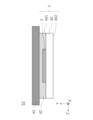
- FIG. 1 is a schematic diagram showing an example of a cross section of a radio wave focusing body according to one embodiment
- FIG. 1 is a schematic diagram showing an example of a cross section of a window glass including a radio wave concentrator according to one embodiment
- FIG. 4 is a schematic diagram showing another example of a cross section of a window glass including a radio wave concentrator according to one embodiment
- FIG. 2 is a diagram schematically showing an example of a radio wave focusing section 21 according to the first embodiment
- FIG. FIG. 3 is a diagram for explaining the principle of operation of the radio wave converging body having the radio wave converging unit 21 according to the first embodiment
- FIG. 4 is a diagram schematically showing another example of the radio wave focusing section 21 according to the first embodiment
- FIG. 10 is a diagram schematically showing an example of a radio wave focusing section 22 according to a second embodiment
- FIG. 10 is a diagram for explaining the principle of operation of a radio wave converging body having a radio wave converging section 22 according to the second embodiment
- FIG. 10 is a diagram schematically showing another example of the radio wave focusing section 22 according to the second embodiment
- FIG. 11 is a diagram schematically showing a radio wave focusing section 23 according to a third embodiment
- FIG. 10 is a diagram showing an example of a unit cell pattern 23unit included in a radio wave focusing unit 23 according to the third embodiment
- FIG. 11 is a diagram for explaining the principle of operation of a radio wave converging body having a radio wave converging section 23 according to a third embodiment;
- FIG. 10 is a diagram for explaining a simulation model of Example 1;
- FIG. 10 is a diagram showing an electric field intensity distribution, which is a simulation result of Example 1;
- FIG. 10 is a diagram showing an electric field intensity distribution, which is a simulation result of Example 2;
- FIG. 11 is a diagram for explaining a simulation model of Example 3;
- FIG. 10 is a diagram showing an electric field intensity distribution, which is a simulation result (part 1) of Example 3;
- FIG. 11 is a diagram showing an example of simulation results (part 2) of Example 3;
- FIG. 11 is a diagram showing a radio wave focusing unit 23 according to example 4;
- FIG. 10 is a diagram showing an electric field strength distribution, which is a simulation result (part 1) of Example 4;
- FIG. 10 is a diagram showing a simulation result (part 2) of Example 4, and is
- a three-dimensional orthogonal coordinate system with three axial directions (X-axis direction, Y-axis direction, Z-axis direction)
- the width direction of the wall is the X-axis direction
- the height direction of the wall is the Z-axis direction
- the wall thickness direction is the Y-axis direction.
- the direction from the bottom to the top of the wall is the +Z-axis direction
- the opposite direction is the -Z-axis direction.
- the +Y-axis direction is the direction from the outdoors to the indoors
- the -Y-axis direction is the opposite direction.
- the +Z-axis direction may be referred to as upward
- the ⁇ Z-axis direction may be referred to as downward
- the +Y-axis direction may be referred to as indoor side
- the ⁇ Y-axis direction may be referred to as indoor side.
- the X-axis direction, Y-axis direction, and Z-axis direction represent the direction parallel to the X-axis, the direction parallel to the Y-axis, and the direction parallel to Z, respectively.
- the X-axis direction, the Y-axis direction, and the Z-axis direction are orthogonal to each other.
- the XY plane, YZ plane, and ZX plane are virtual planes parallel to the X-axis direction and Y-axis direction, virtual planes parallel to the Y-axis direction and Z-axis direction, and virtual planes parallel to the Z-axis direction and X-axis direction, respectively.
- millimeter wave or “millimeter wave band” includes the quasi-millimeter wave band of 24 GHz to 30 GHz in addition to the frequency band of 30 GHz to 300 GHz.
- a “radio wave” is a kind of electromagnetic wave, and generally, an electromagnetic wave of 3 THz or less is called a radio wave.
- electromagnetic waves radiated from base stations or relay stations are referred to as “radio waves”, and electromagnetic waves in general are referred to as “electromagnetic waves”.
- the same elements may be denoted by the same reference numerals, and overlapping descriptions may be omitted.
- FIG. 1 is a schematic diagram showing a radio wave control system 1 according to one embodiment of the present invention.
- a radio wave control system 1 includes a building BD and a radio wave concentrator 3 .
- the radio wave concentrator 3 is used as a window of the building BD, but it is not limited to this, and may be used as a shelter roof of a bus stop or a station platform.
- the XY plane is assumed to be a horizontal plane.
- the walls of the building BD act as shields for millimeter wave band radio waves, and either do not pass such radio waves or attenuate them significantly. Therefore, the millimeter-wave radio waves emitted from the base station pass through the window, not the wall.
- millimeter wave band radio waves that pass through a window travel straight ahead, so areas other than the line of sight (LOS; Line of Sight) (hereinafter also referred to as "LOS1") of the window are areas where the communication environment is not good. become a zone.
- LOS1 most of the millimeter waveband radio waves that have passed through the window reach the wall of the building BD without reaching the electronic equipment, and then attenuate significantly or disappear.
- LOS refers to a straight line of sight when radio waves are perpendicularly incident on the main surface of the radio wave converging body 3 .
- the radio wave intensity of the radio wave transmitted through the window can be reduced indoors or inside the building BD. It can be improved in a wide range of outdoor areas.
- the radio wave control system 1 can deliver the radio waves that have entered the radio wave concentrator 3 to the convergence area F that exists outside the LOS 1 and extends in the X-axis direction.
- the radio waves incident on the radio wave converging body 3 are focused on a convergence region F′ extending in the X-axis direction, which exists in an area within the LOS1 excluding the straight line of sight of the radio wave converging unit 2 (hereinafter also referred to as “LOS2”).
- LOS2 straight line of sight of the radio wave converging unit 2
- the radio wave converging unit 2 is provided on the indoor side in FIG. 1, it may be provided on the outdoor side.
- Fig. 1 the method for improving the radio wave intensity over a wide range indoors when radio waves are radiated from the outdoors has been explained, but it is also possible to improve the radio wave intensity over a wide range outdoors when radio waves are radiated indoors. It is possible as well.
- the radio waves controlled by the radio wave control system 1 are millimeter wave bands such as the fifth generation mobile communication system (5G), frequency bands of 6 GHz or less (hereinafter also referred to as “Sub-6”), LTE (Long Term Evolution), LTE-A (LTE-Advanced), 0.3 to 30 GHz, or 1 to 30 GHz.
- the radio waves to be controlled are UMB (Ultra Mobile Broadband), IEEE802.11 (Wi-Fi (registered trademark)), IEEE802.16 (WiMAX (registered trademark)), IEEE802.20, UWB (Ultra-Wideband), Bluetooth (registered trademark), LPWA (Low Power Wide Area). It may be used in any communication system, such as other enhanced communication systems. It should be noted that as the frequency becomes higher, the propagation loss due to reflection and diffraction becomes larger, and the dead zone as described above tends to occur. Therefore, the radio wave control system 1 of the present invention is more suitable for communication handling relatively high frequencies.
- FIG. 2 is a schematic diagram showing an example of a cross section of the radio wave focusing body 3.
- the radio wave focusing body 3 has a base body 40 having a first main surface 401 and a second main surface 402 facing each other, and a radio wave focusing portion 2 provided on the first main surface 401 .
- the term "principal surface” means a surface perpendicular to the thickness direction of the member.
- the substrate 40 is made of any material that is transparent to electromagnetic waves at the operating frequency of the radio wave control system 1 and capable of supporting the radio wave focusing section 2 .
- transparent means that the luminous transmittance is 60% or more, preferably 70% or more, more preferably 80% or more, and still more preferably 90% or more.
- the substrate 40 is preferably made of glass.
- glass commonly available glass may be used, and examples thereof include soda-lime glass, alkali-free glass, Pyrex (registered trademark) glass, and quartz glass.
- the radio wave focusing body 3 can be used as a window glass.
- the substrate 40 may be made of resin.
- resins include acrylic resins (polymethyl methacrylate, etc.), cycloolefin resins, polycarbonate resins, and the like.
- other members may be laminated. This will be described in detail below with reference to FIGS. 3A and 3B.
- FIG. 3A is a diagram showing an example of a cross section of the window glass 51 including the radio wave concentrator 3.
- the window glass 51 includes a substrate 40 made of resin having a first principal surface 401 and a second principal surface 402 facing each other, a radio wave focusing portion 2 provided on the first principal surface 401 , and an adhesive layer 42 . and a glass plate 43 bonded to the second main surface 402 side via the glass plate 43 .
- FIG. 3B is a diagram showing an example of a cross section of the window glass 52 including the radio wave concentrator 3.
- the window glass 302 includes a substrate 40 made of resin having a first main surface 401 and a second main surface 402 facing each other, a radio wave focusing section 2 provided on the first main surface 401, and an adhesive layer . and a glass plate 43 adhered to the first main surface 401 side via the glass plate 43 .
- the adhesive layer 42 is made of any adhesive material that can bond the resin plate 41 and the glass plate 43 together. Note that the thickness of the adhesive layer 42 is not particularly limited as long as it is equal to or greater than the thickness of the radio wave focusing section 2 .
- the glass plate 43 is made of glass.
- the glass may be any commonly available glass, such as soda lime glass, alkali-free glass, Pyrex (registered trademark) glass, quartz glass, and the like.
- the adhesive layer 42 and the glass plate 43 are transparent to electromagnetic waves at the operating frequency of the radio wave control system 1, like the base 40.
- the radio wave focusing section 2 includes a plurality of conductor regions.
- the conductor region is made of transparent conductive films such as zinc oxide (ZnO), tin oxide (SnO 2 ), tin-doped indium oxide (ITO), indium oxide/tin oxide (IZO), titanium nitride (TiN ) and metal nitride films such as chromium nitride (CrN), Low-e (Low emissivity) films for glass, copper (Cu), silver (Ag), aluminum (Al), chromium (Cr), nickel ( Ni), gold (Au), platinum (Pt), tin (Sn), and iron (Fe).
- transparent conductive films such as zinc oxide (ZnO), tin oxide (SnO 2 ), tin-doped indium oxide (ITO), indium oxide/tin oxide (IZO), titanium nitride (TiN ) and metal nitride films such as chromium nitride (CrN), Low-e (Low emissivity)
- the thickness of the conductor region is preferably 0.1 ⁇ m or more, more preferably 1 ⁇ m or more, still more preferably 5 ⁇ m or more, and particularly preferably 8 ⁇ m or more. If the thickness of the conductor region is 0.1 ⁇ m or more, the sheet resistance value of the conductor region can be reduced.
- the thickness of the conductor region is preferably 50 ⁇ m or less, more preferably 40 ⁇ m or less, still more preferably 30 ⁇ m or less, even more preferably 20 ⁇ m or less, and particularly preferably 15 ⁇ m or less. 1 ⁇ /sq or less is more preferable, and 0.5 ⁇ /sq or less is even more preferable.
- the conductor region may be obtained by forming the above-described metal material over the entire surface of the region (a so-called metal film formed over the entire surface). It may be obtained by forming into a shape. In the case of the mesh shape, the conductor region can increase the transparency of visible light to such an extent that it is difficult to visually confirm, and the visibility is excellent.
- the line width of the fine metal wire is preferably 1 ⁇ m to 10 ⁇ m, more preferably 1 ⁇ m to 5 ⁇ m, even more preferably 1 ⁇ m to 3 ⁇ m. Moreover, the interval between the thin metal wires is preferably 300 ⁇ m to 500 ⁇ m. From the standpoint of strength and manufacturing, an aspect ratio (thickness of fine metal wire/line width of fine metal wire) of 1 or less is preferable.
- the shape of the opening may be square or rhombic, and in the case of square, square is preferable from the viewpoint of design.
- the openings may have a random shape obtained by a self-assembly method, in which case moire can be suppressed.
- the opening ratio of the openings to the entire mesh is preferably 80% or more, more preferably 90% or more. As the aperture ratio is increased, the visible light transmittance of the conductor region can be increased.
- the conductor region may be composed of a metasurface.
- metasurface means an artificial surface that controls transmission and reflection characteristics of incident electromagnetic waves.
- a plurality of conductor regions included in the radio wave focusing unit 2 will be described in more detail below using three embodiments. In the following three embodiments, the case where the electromagnetic wave is incident from the second main surface 402 will be described, but the case where the electromagnetic wave is incident from the first main surface 401 can be similarly described.
- FIG. 4A is a diagram schematically showing an example of the radio wave focusing section 21 according to the first embodiment.
- the radio wave focusing unit 21 includes n (n is a natural number of 2 or more) conductor regions, that is, conductor regions 21-1 to 21-n (hereinafter referred to as Any one of the conductor regions 21-1 to 21-n is also simply referred to as a "first region").
- the shape of the first region is not annular but strip-shaped defined by straight lines. As shown in FIG. 4A, the line width of the first regions becomes narrower along the +Z-axis direction, and the interval between adjacent first regions becomes narrower.
- FIG. 4B is a diagram for explaining the principle of operation of the radio wave converging body 31 having the radio wave converging section 21.
- FIG. 4B as an example, consider a case where an electromagnetic wave (plane wave) is radiated toward the second main surface 402 from an electromagnetic wave generation source S on the second main surface 402 side. If the electromagnetic waves radiated from the source S are spherical waves, the same design is possible by considering the distribution of the incident phases when they are incident on the radio wave concentrator 31 .
- an electromagnetic wave plane wave
- an electromagnetic wave incident on the radio wave focusing portion 21 can be focused on a focusing region F1 extending in the X-axis direction, which is separated from the first main surface 401 by a distance f1 in the +Y-axis direction. The conditions at this time will be described below.
- the distance in the Z-axis direction between the lower side of the conductor region 21-n and the focusing region F1 is D 2n ⁇ 1
- the distance in the Z-axis direction between the upper side of the conductor region 21-n and the focusing region F1 is Assuming that the distance is D2n and the wavelength of the incident electromagnetic wave is ⁇ , the following equation (1) holds.
- the lower side is an example of the first side
- the upper side is an example of the second side.
- the focusing region F1 is formed below the conductor region 21-1 (in the ⁇ Z-axis direction), but its position is not particularly limited. or outside the LOS.
- FIG. 4A illustrates the case where the shape of the first region is a band defined by straight lines
- the shape is not limited as long as the above conditions are satisfied.
- the shape of the first region may be a strip defined by curved lines.
- the focusing area F1 has the same shape as the strip defined by the curve, and the first area and the focusing area F 1 in the Z - axis direction satisfies the above formula (1) or (2).
- the distance f1 may be different in the X-axis direction by changing the Z-direction width of the strip-shaped first region in the X-axis direction while satisfying the expression (1) or (2).
- the position of the focusing area F1 in the Y-axis direction is different in the X-axis direction.
- FIG. 5A is a diagram schematically showing an example of the radio wave focusing section 22 according to the second embodiment.
- the radio wave focusing unit 22 includes n (n is a natural number of 2 or more) conductor regions, that is, conductor regions 22-1 to 22-n (hereinafter referred to as conductor regions 22-1 to conductor Any one of the regions 22-n is also simply referred to as a “second region”).
- the line widths of the second regions are the same, and the intervals between adjacent second regions are also the same.
- FIG. 5B is a diagram for explaining the principle of operation of the radio wave converging body 32 having the radio wave converging section 22.
- FIG. 5B as an example, consider a case where an electromagnetic wave (plane wave) is radiated toward the second main surface 402 from an electromagnetic wave source S on the second main surface 402 side.
- an electromagnetic wave plane wave
- the electromagnetic wave incident on the radio wave concentrator 22 can be delivered to the line segment A2 extending in the X-axis direction outside the LOS of the radio wave concentrator 32 .
- the electromagnetic wave incident on the second main surface 402 is moved within the LOS of the radio wave focusing body 32 and outside the LOS of the radio wave focusing portion 22 by a distance f2 from the first main surface 401 in the +Y-axis direction. It can be focused into a separate, X-axis extending focusing region F2 . The conditions at this time will be described below.
- the above formula (3) is a conditional expression when the electromagnetic waves transmitted through the radio wave converging section 22 are strengthened by the diffraction grating formed in the radio wave converging section 22 .
- the above equation (4) is a conditional expression when the electromagnetic wave that has passed through the radio wave focusing portion 22 and the electromagnetic wave that has not passed through the radio wave focusing portion 22 but has simply passed through the substrate 40 strengthen each other.
- the electromagnetic wave incident on the radio wave focusing portion 22 is refracted by the diffraction grating toward the line segment A2 in the ⁇ direction, and at the same time, it is strengthened with the electromagnetic wave that has passed through the base 40 to form the focusing region F2. do.
- the position of the focusing area F2 is not particularly limited, and may be within the LOS of the radio wave focusing body 32 or outside the LOS.
- FIG. 5A illustrates the case where the shape of the second region is a strip defined by straight lines
- the shape is not limited as long as the lattice constant is constant.
- the shape of the second region may be a strip defined by curved lines.
- the intervals (lattice constant d) of the second regions are all the same, and the focusing region F 2 is the curve It has the same shape as the belt shape defined by.
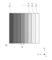
- FIG. 6A is a diagram schematically showing the radio wave focusing section 23 according to the third embodiment.
- the radio wave focusing unit 23 includes n (n is a natural number of 2 or more) strip-shaped regions, that is, strip-shaped regions 23-1 to 23-n (hereinafter referred to as strip-shaped regions 23-1 to 23-n) aligned without gaps.
- ⁇ n is also simply referred to as a “third region”) are arranged without gaps.
- the widths in the Z-axis direction of the third regions are the same.
- the third region is a conductor region formed by the unit cell pattern 23unit, or a region that does not contain a metal film (hereinafter also referred to as "metal film non-containing region"). However, in the radio wave focusing portion 23, the number of metal film non-containing regions is 0 or 1. FIG.
- the conductor area becomes a metasurface.
- metasurface means an artificial surface that controls transmission and reflection characteristics of incident electromagnetic waves. By controlling at least one of the phase and amplitude of the electromagnetic wave incident on the third region, it is possible to realize radio wave characteristics that do not exist in the natural world.
- the third region can transmit, reflect, or focus incident electromagnetic waves in a desired direction.
- the electromagnetic waves transmitted through the band-shaped regions 23-1 to 23-n can have different phases.
- FIG. 6B is a diagram showing an example of the unit cell pattern 23unit included in the third area.
- the third region is formed by repeatedly arranging unit cell patterns 23unit having the size of Lunit in the same direction. That is, the repetition period of the center C of the unit cell pattern 23unit is Lunit.
- the shape of the unit cell pattern 23unit is annular in FIG. 6B, it is not limited to this, and may be, for example, a cross shape, a swastika shape, a rectangular ring shape, a polygonal ring shape, an elliptical ring shape, a patch shape, or the like. may
- the unit cell pattern 23unit may be a metal film made of the metal material described above, or may be obtained by forming fine metal wires made of the metal material described above into a mesh.
- Two unit cell patterns 23unit may be stacked in the Y-axis direction. By stacking two of each unit cell pattern 23unit, the amount of change in the phase of the electromagnetic wave that passes through the conductor region (absolute difference between the phase of the electromagnetic wave before passing through the conductor region and the phase of the electromagnetic wave after passing through the conductor region) value) can be greater than ⁇ /2.
- FIG. 6C is a diagram for explaining the principle of operation of the radio wave converging body 33 having the radio wave converging section 23.
- FIG. 6C as an example, consider a case where an electromagnetic wave (plane wave) is radiated toward the second main surface 402 from an electromagnetic wave generation source S on the second main surface 402 side. If the electromagnetic wave radiated from the antenna is a spherical wave, it can be similarly designed by considering the phase at the time of incidence.
- the electromagnetic waves incident on the radio wave concentrator 23 can be delivered to the line segment A3 extending in the X-axis direction outside the LOS of the radio wave concentrator 33.
- the electromagnetic waves incident on the second main surface 402 are moved within the LOS of the radio wave focusing body 33 and outside the LOS of the radio wave focusing portion 23 by a distance f3 from the first main surface 401 in the +Y-axis direction. It can be focused into a separate, X-axis extending focusing region F3 .
- the conditions at this time will be described below.
- it will be shown in a later example that the effect of improving the intensity of the radio waves can be obtained even outside the LOS of the radio wave converging body 33 .
- the unit cell pattern 23unit is arranged in the third region so that the phase of the electromagnetic wave transmitted through the band-shaped region 23-n is ⁇ +2 ⁇ n/m ( ⁇ : any reference phase, m: any natural number equal to or greater than n). do.
- one of the third regions may be a metal film-free region as long as the above phase condition is satisfied.
- the width of the third region in the Z-axis direction is W
- the angle between the first main surface 401 and the line segment A3 is ⁇
- the wavelength of the incident electromagnetic wave is ⁇
- the natural number are s and t, the relationships of the following equations (5) and (6) hold.
- the above formula (5) is a conditional formula when the electromagnetic wave transmitted through the radio wave focusing section 23 is refracted in the ⁇ direction according to Huygens' principle.
- the above formula (6) is a conditional expression when the electromagnetic wave that has passed through the radio wave focusing portion 23 and the electromagnetic wave that has not passed through the radio wave focusing portion 23 but has simply passed through the substrate 40 strengthen each other.
- the electromagnetic wave incident on the radio wave focusing section 23 is refracted by the diffraction grating toward the line segment A3 in the ⁇ direction, and at the same time, it is strengthened with the electromagnetic wave that has passed through the substrate 40 to form the focusing area F3 . do.
- the radio wave converging section 23 formed of n band-shaped areas has been described, but a plurality of such radio converging sections 23 may be used without gaps. At this time, the values of n and m in each radio wave focusing unit 23 may be different.
- Example> The inventors of the present invention have verified the above-described first to third embodiments through simulations. The results are shown in Examples 1 to 4 below.
- FIG. 7 is a diagram for explaining a simulation model of Example 1.
- the radio wave focusing unit 21 or the wall 70 connected below the radio wave focusing unit 21 ( ⁇ Z axis direction) is installed on the -Y axis direction side.
- a radio wave (plane wave) is radiated from a radio wave source S.
- the electric field intensity of radio waves was observed in the focusing region F1 , which is separated from the radio wave focusing portion 21 (or the wall 70) by the distance f1 in the +Y-axis direction and which extends infinitely in the X-axis direction.
- the model in Example 1 includes three models. Specifically, a model having only the radio wave focusing unit 21 (model A), a model having the radio wave focusing unit 21 and the wall 70 (model B), and a model having only the wall 70 without the radio wave focusing unit 21 (model C).
- model A a model having only the radio wave focusing unit 21
- model B a model having the radio wave focusing unit 21 and the wall 70
- model C a model having only the wall 70 without the radio wave focusing unit 21
- the thicknesses of the radio wave focusing portion 21 and the wall 70 are virtually zero
- the radio wave focusing portion 21 extends infinitely in the X-axis direction
- the wall 70 extends infinitely in the ⁇ Z-axis direction. It is assumed that there is
- f1 was 150 mm and wavelength ⁇ was 61.2 mm (frequency 4.9 GHz).
- the radio wave focusing unit 21 is assumed to have n of 11 in FIG. 4A. That is, formed by the conductor regions 21-1 to 21-11 (first region), the line width of the first region becomes narrower along the +Z-axis direction, and the interval between adjacent first regions becomes narrower. and
- D 1 to D 22 are set according to formula (2). For example, D1 was 100.6 mm and D22 was 809.2 mm.
- the width of the radio wave focusing portion 21 in the Z-axis direction was set to 708.6 mm (D 22 -D 1 ).
- the conductor region was obtained by forming a perfect electrical conductor (a metal with zero electrical resistance) over the entire surface of the region.
- FIG. 8 is a diagram showing an electric field intensity distribution, which is a simulation result of Example 1.
- the horizontal axis represents the position (Y coordinate) of the focusing area F1 in the Y axis direction when the Y coordinate of the surface of the radio wave focusing section 21 (or wall 70) is zero.
- the vertical axis indicates the electric field strength at the position of the focusing region F1 .
- model A and model B having the radio wave focusing portion 21 the electric field intensity was the strongest at the position of the focusing region F1 .
- model A without wall 70 had a stronger electric field strength.
- model C which does not have the radio wave focusing portion, no change in the electric field strength was observed at the position of the focusing region F1 .
- the sub-6 band radio waves incident on the radio wave converging unit 21 are converged on the convergence region F1 existing below the radio wave converging unit 21 ( ⁇ Z axis direction). It was shown that it is possible to
- Example 2 In Example 2, the wavelength ⁇ was set to 10.7 mm (frequency of 28 GHz), and accordingly the line width and spacing of the first region of the radio wave focusing section 21 were changed. A simulation was performed in the same manner as in Example 1 except that the settings were reset. At this time, in the radio wave converging portion 21, for example, D1 is 40.4 mm, D22 is 221.8 mm, and the width of the radio wave converging portion 21 in the Z-axis direction is 181.4 mm ( D22 - D1 ).
- FIG. 9 is a diagram showing an electric field intensity distribution, which is a simulation result of Example 2.
- FIG. 9 shows the electric field intensity distribution at the same height as the focusing area F1 when the Y coordinate of the surface of the radio wave focusing portion 21 (or the wall 70) is zero.
- model A and model B having the radio wave focusing portion 21 the electric field strength was the strongest at the position of the focusing region F1 .
- model A without wall 70 had a stronger electric field strength.
- model C which does not have the radio wave focusing portion, no change in the electric field strength was observed at the position of the focusing region F1 .
- the millimeter wave band radio waves incident on the radio wave focusing unit 21 are focused on the focusing area F1 existing below ( ⁇ Z axis direction) the radio wave focusing unit 21 . was shown to be possible.
- Example 3 10A and 10B are diagrams for explaining a simulation model of Example 3.
- FIG. 10 in the model of Example 3, radio waves (plane waves) were radiated from the radio wave source S installed on the -Y-axis direction side of the radio wave focusing unit 22 . In this way, the electric field intensity of radio waves was observed for each distance in the +Y-axis direction from the radio wave converging section 22 .
- the thickness of the radio wave converging portion 22 is virtually zero, and the radio wave converging portion 22 extends infinitely in the X-axis direction.
- the wavelength ⁇ was 10.7 mm (frequency 28 GHz).
- n in FIG. 5A is assumed to be 6. That is, the conductor regions 22-1 to 22-6 (second regions) are formed, and each second region has a width of 11.1 mm in the Z-axis direction and a lattice constant d of 21.42 mm. . Therefore, the width of the radio wave focusing portion 22 in the Z-axis direction was 118.2 mm.
- the conductor region was obtained by forming a perfect electrical conductor over the entire surface of the region.
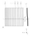
- FIG. 11A is a diagram showing the electric field intensity distribution, which is the simulation result (Part 1) of Example 3.
- Part 1 the simulation result of Example 3.
- the position indicated by the dotted line in the drawing that is, when the Y-coordinate of the surface of the radio wave converging portion 22 is zero, the radio wave converging portion 22 is separated downward by 40.4 mm ( ⁇ Z axis direction). It shows the electric field intensity distribution at height.
- FIG. 11B is a diagram showing the simulation results (Part 2) of Example 3, showing the electric field intensity distribution.
- the simulation results of Example 3 (Part 2) are calculated for Models A, B, and C.
- Model A as shown in FIG. 5B, is a model in which the radio wave focusing portion 22 is provided on the first main surface 401 of the substrate 40, and the substrate 40 is provided in the window of the wall 70 (see FIG. 7). Since the substrate 40 is larger than the radio wave focusing portion 22 in a plan view seen from the +Y-axis direction, there are portions where only the substrate 40 exists on both sides of the radio wave focusing portion 22 in the X-axis direction and the Z-axis direction. The portion where only substrate 40 exists is in line of sight, such as the portion of LOS1 in FIG. 1 excluding LOS2.
- a model B is a model in which the radio wave focusing portion 22 is provided on the first main surface 401 of the base 40 , and the base 40 is provided in the window of the wall 70 .
- the size of the radio wave converging portion 22 in a plan view seen from the +Y axis direction side is equal to the size of the radio wave converging portion 22 of the model A
- the size of the base 40 of the model B in a plan view seen from the +Y axis direction side. is equal to the size of the radio wave focusing section 22 .
- the size of the window in the wall 70 of model B in plan view is equal to the size of the substrate 40 .
- the base 40 and the window are smaller than in model A, and the wall 70 covers the portion where the base 40 and the window are reduced.
- the walls 70 are larger as the substrate 40 and window are smaller.
- the model C is a model obtained by removing the radio wave focusing unit 22 from the model B.
- the radio wave intensity is a value at the position indicating the convergence area F' shown in FIG. This position is in the line of sight (within the LOS) for model A, but is outside the line of sight (out of the LOS) for models B and C due to the enlarged wall 70 .
- FIG. 11A The results for model A are the same as those shown in FIG. 11A.
- FIG. 11B differs from FIG. 11A in the scale of the vertical axis.
- model C has a very low electric field strength, but model B shows a tendency for the electric field strength to increase before and after the position of f 1 (150 mm). From this, it can be confirmed that the electric field strength of the radio wave increases outside the LOS even when the radio wave focusing section 22 as a diffraction grating is used and there is no constructive interaction with the radio waves that do not pass through the radio wave focusing section 22. rice field.
- Example 4 In Example 4, the simulation was performed in the same manner as in Example 3 except that the radio wave focusing unit 23 was used instead of the radio wave focusing unit 22 .
- the radio wave focusing unit 23 was as shown in FIG. 12A. 6A (hereinafter, also referred to as “radio wave converging units 231”) are arranged without gaps.
- the radio wave converging portion 231 was formed of strip regions 23-1 to 23-4 (third regions), and the width W of each third region in the Z-axis direction was 8.03 mm.
- the band-shaped region 23-4 is a region that does not contain a metal film, and the band-shaped region 23-1 to band-shaped region 23-3 each have an annular unit cell pattern 23unit with a size Lunit of 2.68 mm. was superimposed on two.
- the unit cell patterns 23unit having the same shape in a plan view viewed from the +Y-axis direction facing the first main surface 401 are provided on the first main surface 401 and the second main surface 402 of the substrate 40, and When viewed from above, the unit cell patterns 23unit on both sides overlap.
- the outer diameter and inner diameter of the annular unit cell pattern 23unit are set so that the phase of the radio wave transmitted through the band-shaped region 23-n (n: an integer of 1 to 4) satisfies ⁇ +2 ⁇ n/4 ( ⁇ : 0°).
- the strip region 23-1 has an outer diameter of 1.2 mm and an inner diameter of 1.1 mm
- the strip region 23-2 has an outer diameter of 1 mm and an inner diameter of 0.9 mm
- the strip region 23-3 has an outer diameter of 0.74 mm and an inner diameter of 0 .64 mm.
- the unit cell pattern 23unit was obtained by forming a perfect electrical conductor in the annular shape.
- FIG. 12B is a diagram showing the electric field intensity distribution, which is the simulation result (Part 1) of Example 4.
- the wave incident on the radio wave focusing portion 23 is refracted by Huygens' principle.
- the radio waves that were picked up and the radio waves that simply went straight without being incident on the radio wave converging section 23 strengthened each other at a plurality of Y-coordinates according to the above formulas (5) and (6), and the electric field strength increased.
- the radio wave focusing unit 23 by using the radio wave focusing unit 23, the electric field intensity of the radio waves of Sub-6 that pass through the radio wave focusing unit 23 can be strengthened at a position below the radio wave focusing unit 23 (in the ⁇ Z-axis direction). was shown to be
- FIG. 12C is a diagram showing the simulation results (Part 2) of Example 4, showing the electric field intensity distribution.
- the simulation results of Example 4 (Part 2) are calculated for Models A, B, and C.
- Models AC are identical to models AC used to obtain the simulation results of FIG. 11B.
- FIG. 12C The results for model A in FIG. 12C are the same as those shown in FIG. 12B.
- FIG. 12C differs from FIG. 12B in the scale of the vertical axis.
- model C has a very low electric field intensity, but model B shows a tendency to increase the overall electric field intensity compared to model C. From this, it can be confirmed that the electric field strength of the radio wave increases outside the LOS even when the radio wave focusing section 23 as a diffraction grating is used and there is no constructive interaction with the radio waves that do not pass through the radio wave focusing section 23. rice field.
- radio wave concentrators and glazings of exemplary embodiments of the present disclosure have been described above, the present disclosure is not limited to the specifically disclosed embodiments and departs from the scope of the claims. Various modifications and changes are possible.
- radio wave control system 2 radio wave focusing unit 3
- radio wave focusing body 40 base 401 first main surface 402 second main surface 41 resin plate 42 adhesive layer 43 glass plates 51, 52 window glasses 21, 22, 23 radio wave focusing unit 21-n, 22-n Conductor region 23-n Strip region 23unit Unit cell pattern
Landscapes
- Aerials With Secondary Devices (AREA)
Priority Applications (1)
| Application Number | Priority Date | Filing Date | Title |
|---|---|---|---|
| JP2023572437A JPWO2023132274A1 (https=) | 2022-01-06 | 2022-12-23 |
Applications Claiming Priority (2)
| Application Number | Priority Date | Filing Date | Title |
|---|---|---|---|
| JP2022000999 | 2022-01-06 | ||
| JP2022-000999 | 2022-01-06 |
Publications (1)
| Publication Number | Publication Date |
|---|---|
| WO2023132274A1 true WO2023132274A1 (ja) | 2023-07-13 |
Family
ID=87073606
Family Applications (1)
| Application Number | Title | Priority Date | Filing Date |
|---|---|---|---|
| PCT/JP2022/047596 Ceased WO2023132274A1 (ja) | 2022-01-06 | 2022-12-23 | 電波集束体および窓ガラス |
Country Status (2)
| Country | Link |
|---|---|
| JP (1) | JPWO2023132274A1 (https=) |
| WO (1) | WO2023132274A1 (https=) |
Citations (5)
| Publication number | Priority date | Publication date | Assignee | Title |
|---|---|---|---|---|
| JPS5112755A (en) * | 1974-07-23 | 1976-01-31 | Mitsubishi Electric Corp | Horogurafuitsuku antena |
| JPH04134909A (ja) * | 1990-09-26 | 1992-05-08 | Arimura Giken Kk | 回折リング型アンテナ |
| JP2002164735A (ja) * | 2000-11-28 | 2002-06-07 | Kobe Steel Ltd | マイクロ波無線通信システムにおける無給電中継装置 |
| JP2005191982A (ja) * | 2003-12-26 | 2005-07-14 | Kobe Steel Ltd | アンテナ |
| WO2019198702A1 (ja) * | 2018-04-09 | 2019-10-17 | 株式会社村田製作所 | 電磁波伝搬制御部材、電磁波伝搬制御構造体、電磁波伝搬制御部材付きサッシ、窓構造体及び電子機器 |
Family Cites Families (4)
| Publication number | Priority date | Publication date | Assignee | Title |
|---|---|---|---|---|
| ES2177309T3 (es) * | 1998-03-10 | 2002-12-01 | Qinetiq Ltd | Sistema tridimensional de formacion de imagenes. |
| FR2980648B1 (fr) * | 2011-09-26 | 2014-05-09 | Thales Sa | Antenne lentille comprenant un composant dielectrique diffractif apte a mettre en forme un front d'onde hyperfrequence |
| EP3828994B1 (en) * | 2018-10-05 | 2024-07-31 | Agc Inc. | Antenna system |
| JP7265462B2 (ja) * | 2019-09-30 | 2023-04-26 | Kddi株式会社 | 電波透過板および電波透過システム |
-
2022
- 2022-12-23 JP JP2023572437A patent/JPWO2023132274A1/ja active Pending
- 2022-12-23 WO PCT/JP2022/047596 patent/WO2023132274A1/ja not_active Ceased
Patent Citations (5)
| Publication number | Priority date | Publication date | Assignee | Title |
|---|---|---|---|---|
| JPS5112755A (en) * | 1974-07-23 | 1976-01-31 | Mitsubishi Electric Corp | Horogurafuitsuku antena |
| JPH04134909A (ja) * | 1990-09-26 | 1992-05-08 | Arimura Giken Kk | 回折リング型アンテナ |
| JP2002164735A (ja) * | 2000-11-28 | 2002-06-07 | Kobe Steel Ltd | マイクロ波無線通信システムにおける無給電中継装置 |
| JP2005191982A (ja) * | 2003-12-26 | 2005-07-14 | Kobe Steel Ltd | アンテナ |
| WO2019198702A1 (ja) * | 2018-04-09 | 2019-10-17 | 株式会社村田製作所 | 電磁波伝搬制御部材、電磁波伝搬制御構造体、電磁波伝搬制御部材付きサッシ、窓構造体及び電子機器 |
Also Published As
| Publication number | Publication date |
|---|---|
| JPWO2023132274A1 (https=) | 2023-07-13 |
Similar Documents
| Publication | Publication Date | Title |
|---|---|---|
| KR102632951B1 (ko) | 유리용 안테나 유닛, 안테나 구비 유리판, 및 유리용 안테나 유닛의 제조 방법 | |
| US12261367B2 (en) | Antenna unit and window glass | |
| KR20180042543A (ko) | 필름 적층물 및 이를 포함하는 윈도우 제조물 | |
| JPWO2019107514A1 (ja) | アンテナユニット、およびアンテナ付きガラス板 | |
| WO2023153328A1 (ja) | フレネルゾーンプレートレンズ、フレネルゾーンプレートレンズ一体型窓ガラス、及びフレネルゾーンプレートレンズ付き窓ガラス | |
| US12057631B2 (en) | Antenna unit and window glass | |
| CN105609937A (zh) | 一种光透明天线 | |
| US20240120664A1 (en) | Antenna device and window glass for building | |
| CN102682858A (zh) | 吸波材料 | |
| TW202245339A (zh) | 相位調整板、玻璃板及無線通信系統 | |
| US20250309551A1 (en) | Radio transmission system | |
| WO2023120471A1 (ja) | 電波集束体、窓ガラス、及び、電波通信システム | |
| CN116111335A (zh) | 透光天线 | |
| WO2023132274A1 (ja) | 電波集束体および窓ガラス | |
| CN112103661A (zh) | 透明柔性宽带微波低散射结构及透明柔性蒙皮 | |
| JP6965989B2 (ja) | 電磁波伝搬制御部材、電磁波伝搬制御構造体、電磁波伝搬制御部材付きサッシ及び窓構造体 | |
| JP7816378B2 (ja) | 電波集束体、及び、窓ガラス | |
| US20240145937A1 (en) | Radio wave control system | |
| TW202410552A (zh) | 反射板、使用其之電磁波反射裝置、及電磁波反射柵 | |
| TW202410553A (zh) | 反射板、電磁波反射裝置及電磁波反射柵 | |
| JP2025009862A (ja) | 金属反射体 | |
| CN102751583B (zh) | 偏置后馈式卫星电视天线及卫星电视收发系统 | |
| TW202410551A (zh) | 無線傳輸系統 | |
| Huang et al. | Optically Transparent Intelligent Reflecting Surface Assisted 5G Network Coverage Enhancement | |
| WO2025142894A1 (ja) | 電波透過構造体 |
Legal Events
| Date | Code | Title | Description |
|---|---|---|---|
| 121 | Ep: the epo has been informed by wipo that ep was designated in this application |
Ref document number: 22918858 Country of ref document: EP Kind code of ref document: A1 |
|
| WWE | Wipo information: entry into national phase |
Ref document number: 2023572437 Country of ref document: JP |
|
| NENP | Non-entry into the national phase |
Ref country code: DE |
|
| 122 | Ep: pct application non-entry in european phase |
Ref document number: 22918858 Country of ref document: EP Kind code of ref document: A1 |