WO2023132181A1 - 蓄電モジュール - Google Patents
蓄電モジュール Download PDFInfo
- Publication number
- WO2023132181A1 WO2023132181A1 PCT/JP2022/045162 JP2022045162W WO2023132181A1 WO 2023132181 A1 WO2023132181 A1 WO 2023132181A1 JP 2022045162 W JP2022045162 W JP 2022045162W WO 2023132181 A1 WO2023132181 A1 WO 2023132181A1
- Authority
- WO
- WIPO (PCT)
- Prior art keywords
- stacking direction
- portions
- storage module
- sheet member
- current collector
- Prior art date
- Legal status (The legal status is an assumption and is not a legal conclusion. Google has not performed a legal analysis and makes no representation as to the accuracy of the status listed.)
- Ceased
Links
Images



Classifications
-
- H—ELECTRICITY
- H01—ELECTRIC ELEMENTS
- H01G—CAPACITORS; CAPACITORS, RECTIFIERS, DETECTORS, SWITCHING DEVICES, LIGHT-SENSITIVE OR TEMPERATURE-SENSITIVE DEVICES OF THE ELECTROLYTIC TYPE
- H01G11/00—Hybrid capacitors, i.e. capacitors having different positive and negative electrodes; Electric double-layer [EDL] capacitors; Processes for the manufacture thereof or of parts thereof
- H01G11/78—Cases; Housings; Encapsulations; Mountings
-
- H—ELECTRICITY
- H01—ELECTRIC ELEMENTS
- H01G—CAPACITORS; CAPACITORS, RECTIFIERS, DETECTORS, SWITCHING DEVICES, LIGHT-SENSITIVE OR TEMPERATURE-SENSITIVE DEVICES OF THE ELECTROLYTIC TYPE
- H01G11/00—Hybrid capacitors, i.e. capacitors having different positive and negative electrodes; Electric double-layer [EDL] capacitors; Processes for the manufacture thereof or of parts thereof
- H01G11/78—Cases; Housings; Encapsulations; Mountings
- H01G11/80—Gaskets; Sealings
-
- H—ELECTRICITY
- H01—ELECTRIC ELEMENTS
- H01M—PROCESSES OR MEANS, e.g. BATTERIES, FOR THE DIRECT CONVERSION OF CHEMICAL ENERGY INTO ELECTRICAL ENERGY
- H01M10/00—Secondary cells; Manufacture thereof
- H01M10/04—Construction or manufacture in general
-
- H—ELECTRICITY
- H01—ELECTRIC ELEMENTS
- H01M—PROCESSES OR MEANS, e.g. BATTERIES, FOR THE DIRECT CONVERSION OF CHEMICAL ENERGY INTO ELECTRICAL ENERGY
- H01M10/00—Secondary cells; Manufacture thereof
- H01M10/05—Accumulators with non-aqueous electrolyte
- H01M10/052—Li-accumulators
-
- H—ELECTRICITY
- H01—ELECTRIC ELEMENTS
- H01M—PROCESSES OR MEANS, e.g. BATTERIES, FOR THE DIRECT CONVERSION OF CHEMICAL ENERGY INTO ELECTRICAL ENERGY
- H01M10/00—Secondary cells; Manufacture thereof
- H01M10/05—Accumulators with non-aqueous electrolyte
- H01M10/058—Construction or manufacture
- H01M10/0585—Construction or manufacture of accumulators having only flat construction elements, i.e. flat positive electrodes, flat negative electrodes and flat separators
-
- H—ELECTRICITY
- H01—ELECTRIC ELEMENTS
- H01M—PROCESSES OR MEANS, e.g. BATTERIES, FOR THE DIRECT CONVERSION OF CHEMICAL ENERGY INTO ELECTRICAL ENERGY
- H01M10/00—Secondary cells; Manufacture thereof
- H01M10/60—Heating or cooling; Temperature control
- H01M10/61—Types of temperature control
- H01M10/613—Cooling or keeping cold
-
- H—ELECTRICITY
- H01—ELECTRIC ELEMENTS
- H01M—PROCESSES OR MEANS, e.g. BATTERIES, FOR THE DIRECT CONVERSION OF CHEMICAL ENERGY INTO ELECTRICAL ENERGY
- H01M10/00—Secondary cells; Manufacture thereof
- H01M10/60—Heating or cooling; Temperature control
- H01M10/62—Heating or cooling; Temperature control specially adapted for specific applications
- H01M10/625—Vehicles
-
- H—ELECTRICITY
- H01—ELECTRIC ELEMENTS
- H01M—PROCESSES OR MEANS, e.g. BATTERIES, FOR THE DIRECT CONVERSION OF CHEMICAL ENERGY INTO ELECTRICAL ENERGY
- H01M10/00—Secondary cells; Manufacture thereof
- H01M10/60—Heating or cooling; Temperature control
- H01M10/64—Heating or cooling; Temperature control characterised by the shape of the cells
- H01M10/647—Prismatic or flat cells, e.g. pouch cells
-
- H—ELECTRICITY
- H01—ELECTRIC ELEMENTS
- H01M—PROCESSES OR MEANS, e.g. BATTERIES, FOR THE DIRECT CONVERSION OF CHEMICAL ENERGY INTO ELECTRICAL ENERGY
- H01M10/00—Secondary cells; Manufacture thereof
- H01M10/60—Heating or cooling; Temperature control
- H01M10/65—Means for temperature control structurally associated with the cells
- H01M10/655—Solid structures for heat exchange or heat conduction
- H01M10/6556—Solid parts with flow channel passages or pipes for heat exchange
-
- H—ELECTRICITY
- H01—ELECTRIC ELEMENTS
- H01M—PROCESSES OR MEANS, e.g. BATTERIES, FOR THE DIRECT CONVERSION OF CHEMICAL ENERGY INTO ELECTRICAL ENERGY
- H01M50/00—Constructional details or processes of manufacture of the non-active parts of electrochemical cells other than fuel cells, e.g. hybrid cells
- H01M50/10—Primary casings; Jackets or wrappings
- H01M50/102—Primary casings; Jackets or wrappings characterised by their shape or physical structure
- H01M50/103—Primary casings; Jackets or wrappings characterised by their shape or physical structure prismatic or rectangular
-
- H—ELECTRICITY
- H01—ELECTRIC ELEMENTS
- H01M—PROCESSES OR MEANS, e.g. BATTERIES, FOR THE DIRECT CONVERSION OF CHEMICAL ENERGY INTO ELECTRICAL ENERGY
- H01M50/00—Constructional details or processes of manufacture of the non-active parts of electrochemical cells other than fuel cells, e.g. hybrid cells
- H01M50/10—Primary casings; Jackets or wrappings
- H01M50/102—Primary casings; Jackets or wrappings characterised by their shape or physical structure
- H01M50/105—Pouches or flexible bags
-
- H—ELECTRICITY
- H01—ELECTRIC ELEMENTS
- H01M—PROCESSES OR MEANS, e.g. BATTERIES, FOR THE DIRECT CONVERSION OF CHEMICAL ENERGY INTO ELECTRICAL ENERGY
- H01M50/00—Constructional details or processes of manufacture of the non-active parts of electrochemical cells other than fuel cells, e.g. hybrid cells
- H01M50/10—Primary casings; Jackets or wrappings
- H01M50/116—Primary casings; Jackets or wrappings characterised by the material
- H01M50/124—Primary casings; Jackets or wrappings characterised by the material having a layered structure
-
- H—ELECTRICITY
- H01—ELECTRIC ELEMENTS
- H01M—PROCESSES OR MEANS, e.g. BATTERIES, FOR THE DIRECT CONVERSION OF CHEMICAL ENERGY INTO ELECTRICAL ENERGY
- H01M50/00—Constructional details or processes of manufacture of the non-active parts of electrochemical cells other than fuel cells, e.g. hybrid cells
- H01M50/10—Primary casings; Jackets or wrappings
- H01M50/116—Primary casings; Jackets or wrappings characterised by the material
- H01M50/124—Primary casings; Jackets or wrappings characterised by the material having a layered structure
- H01M50/126—Primary casings; Jackets or wrappings characterised by the material having a layered structure comprising three or more layers
- H01M50/129—Primary casings; Jackets or wrappings characterised by the material having a layered structure comprising three or more layers with two or more layers of only organic material
-
- H—ELECTRICITY
- H01—ELECTRIC ELEMENTS
- H01M—PROCESSES OR MEANS, e.g. BATTERIES, FOR THE DIRECT CONVERSION OF CHEMICAL ENERGY INTO ELECTRICAL ENERGY
- H01M50/00—Constructional details or processes of manufacture of the non-active parts of electrochemical cells other than fuel cells, e.g. hybrid cells
- H01M50/10—Primary casings; Jackets or wrappings
- H01M50/172—Arrangements of electric connectors penetrating the casing
- H01M50/174—Arrangements of electric connectors penetrating the casing adapted for the shape of the cells
- H01M50/178—Arrangements of electric connectors penetrating the casing adapted for the shape of the cells for pouch or flexible bag cells
-
- Y—GENERAL TAGGING OF NEW TECHNOLOGICAL DEVELOPMENTS; GENERAL TAGGING OF CROSS-SECTIONAL TECHNOLOGIES SPANNING OVER SEVERAL SECTIONS OF THE IPC; TECHNICAL SUBJECTS COVERED BY FORMER USPC CROSS-REFERENCE ART COLLECTIONS [XRACs] AND DIGESTS
- Y02—TECHNOLOGIES OR APPLICATIONS FOR MITIGATION OR ADAPTATION AGAINST CLIMATE CHANGE
- Y02E—REDUCTION OF GREENHOUSE GAS [GHG] EMISSIONS, RELATED TO ENERGY GENERATION, TRANSMISSION OR DISTRIBUTION
- Y02E60/00—Enabling technologies; Technologies with a potential or indirect contribution to GHG emissions mitigation
- Y02E60/10—Energy storage using batteries
-
- Y—GENERAL TAGGING OF NEW TECHNOLOGICAL DEVELOPMENTS; GENERAL TAGGING OF CROSS-SECTIONAL TECHNOLOGIES SPANNING OVER SEVERAL SECTIONS OF THE IPC; TECHNICAL SUBJECTS COVERED BY FORMER USPC CROSS-REFERENCE ART COLLECTIONS [XRACs] AND DIGESTS
- Y02—TECHNOLOGIES OR APPLICATIONS FOR MITIGATION OR ADAPTATION AGAINST CLIMATE CHANGE
- Y02P—CLIMATE CHANGE MITIGATION TECHNOLOGIES IN THE PRODUCTION OR PROCESSING OF GOODS
- Y02P70/00—Climate change mitigation technologies in the production process for final industrial or consumer products
- Y02P70/50—Manufacturing or production processes characterised by the final manufactured product
Definitions
- the present disclosure relates to power storage modules.
- Patent Document 1 describes an assembled battery. This assembled battery is obtained by stacking a plurality of sheet-type polymer secondary batteries (unit cells) and connecting each unit cell in series.
- This assembled battery includes a metal upper armor plate that also serves as a positive electrode current collector, a metal lower armor plate that also serves as a negative electrode current collector, and a metal intermediate armor plate that also serves as a positive and negative electrode current collector. ing. Rectangular frame-shaped resin sealing bodies are provided between the upper armor plate and the intermediate armor plate and between the lower armor plate and the intermediate armor plate, respectively.
- the sealing member is thermally welded to each exterior plate.
- a power generation element is arranged in a space surrounded by each exterior plate and the sealing member.
- the power generation element is composed of a positive electrode layer, a negative electrode layer, and a gel electrolyte layer interposed between the positive electrode layer and the negative electrode layer.
- the gel electrolyte layer contains a non-aqueous electrolyte and a polymer that retains this electrolyte.
- each power generation element is sealed with a metal exterior plate and a resin frame-like sealing member.
- resins are known to be more permeable to moisture than metals. Sealing with a frame-shaped sealing member made of resin may not be able to sufficiently suppress the intrusion of moisture from the outside.
- An object of the present disclosure is to provide an electricity storage module capable of suppressing moisture intrusion while suppressing short circuits.
- a power storage module includes a laminate having an outer surface, and a sheet member provided in close contact with the laminate so as to cover the outer surface in a cross section along the stacking direction of the laminate,
- the sheet member includes a metal layer, and a first insulating layer laminated on the metal layer and arranged on the outer surface side of the metal layer, and the laminate includes a plurality of electrodes laminated along the lamination direction,
- Each of the electrodes includes a current collector, the electrolyte is housed in a space between adjacent current collectors in the stacking direction, and the sealing part is the space is a frame-shaped member for sealing an electrolyte in the frame, and the electrodes include a plurality of bipolar electrodes, a positive terminal electrode, and a negative terminal terminal electrode, each of the bipolar electrodes including a current collector and a current collector
- a positive electrode active material layer provided on one side of the body and a negative electrode active material layer provided on the other side of the current collector, and the positive electrode active material layer and the negative electrode
- the positive electrode terminating electrode has a current collector and a positive electrode active material layer provided on one side of the current collector, and is laminated to the bipolar electrode at one end in the stacking direction of the laminate.
- the terminating electrode has a current collector and a negative electrode active material layer provided on the other side of the current collector, and is stacked on the bipolar electrode at the other end in the stacking direction of the stack.
- the space is sealed by welding a plurality of frame-shaped first resin layers provided on the peripheral edge of each of the plurality of current collectors and the ends of the plurality of first resin layers on the opposite side of the space.
- the outer surface includes the end surface of the second resin layer opposite to the space and the outer side in the stacking direction of the first resin layer provided on the current collector of the positive terminal electrode.
- the outer surface of the current collector in the stacking direction includes an exposed portion exposed to the outside from the sealing portion, and the sheet member extends from the first surface to the second surface through the end surface, In a cross-section along a direction, it is divided into a plurality of portions insulated from each other.
- the laminate includes a plurality of bipolar electrodes, positive terminal electrodes, and negative terminal electrodes.
- a frame-shaped sealing portion for sealing the electrolyte is provided in the space between the current collectors of each electrode.
- the sealing portion includes a first resin layer provided on each current collector and a second resin layer that seals the space by welding the outer ends of the first resin layer to each other.
- the outer surface of the laminate includes a first surface, a second surface, and an end surface. The first surface and the second surface are the outer surfaces in the stacking direction of the first resin layers provided on the positive terminal electrode and the negative terminal electrode, respectively.
- the end surface is the outer surface of the second resin layer.
- a sheet member including a metal layer is provided in close contact so as to cover the outer surface of the laminate. Since the metal layer included in the sheet member has a high moisture barrier property, penetration of moisture is suppressed as compared with the case where only the resin layer is used.
- the sheet member extends from the first surface to the second surface through the end surface and is divided into a plurality of mutually insulated portions within a cross section along the stacking direction. Therefore, although the outer surfaces of the current collectors of the positive terminal electrode and the negative terminal electrode include an exposed portion exposed to the outside from the sealing portion, the positive terminal electrode and the negative terminal electrode are short-circuited through the sheet member. is suppressed. As described above, according to this power storage module, it is possible to suppress a short circuit when suppressing moisture intrusion.
- the adjacent portions among the plurality of divided portions of the sheet member may include overlapping portions that overlap each other.
- the portion of the sealing portion exposed from the sheet member is reduced, and intrusion of not only moisture but also air (nitrogen, oxygen, etc.) is suppressed.
- adjacent portions of the plurality of divided sheet member portions are spaced apart so as to form a gap between the ends of each other, and the gap includes an insulating member may be placed.
- the plurality of portions of the sheet member are spaced apart from each other in this way, it is possible to reliably suppress breakage of the metal layer due to deformation of the sheet member following expansion and contraction of the sealing portion due to heat. .
- the gas generated inside the sheet member escapes through the gap, thereby suppressing an increase in internal pressure.
- the sealing portion includes a plurality of frame-shaped third resin layers, and the third resin layers are arranged so as to be interposed between the first resin layers adjacent in the stacking direction.
- the second resin layer may seal the spaces by welding the ends of the plurality of first resin layers and the ends of the plurality of third resin layers opposite to the spaces. In this case, a plurality of spaces can be collectively sealed by the second resin layer integrally formed along the stacking direction, and the manufacturing thereof is easy.
- the sheet member includes the second insulating layer laminated on the metal layer on the side opposite to the first insulating layer, and at the overlapping portion, the one portion of the first insulating layer and the one portion Electrical insulation may be formed by overlapping the second insulating layer of another portion adjacent to the second insulating layer.
- the insulation can be easily ensured by overlapping the respective portions of the sheet member.
- one portion relatively vertically upward may overlap another portion relatively vertically downward at the overlapping portion.
- water flowing vertically downward from the vertically upward direction is prevented from being accumulated in overlapping portions of the respective portions of the sheet member.
- the power storage module according to the present disclosure may include an insulating tape attached to the sheet member so as to cover the overlapping portion. In this case, it is possible to prevent peeling at overlapping portions of the sheet members, and to reliably suppress moisture intrusion.
- the plurality of portions includes a first portion extending from the first surface over the end surface and a second portion extending from the second surface over the end surface.
- the portions may overlap each other on the end face.
- the plurality of portions includes the first portion arranged on the first surface, the second portion arranged on the second surface, and the first portion and the second portion from the end surface. and a third portion extending to overlap with each of the first and second portions, wherein the third portion overlaps with each of the first and second portions, wherein the third portion is outside the first and second portions may be superimposed on
- the plurality of portions includes the first portion arranged on the first surface, the second portion arranged on the second surface, and the first portion and the second portion from the end surface. and a third portion extending so as to overlap with each of the first portion and the third portion, in the overlapping portion of the first portion and the third portion, in the cross section along the stacking direction, the end of the third portion is the first portion
- the end of the first part and the end of the third part are in contact so that the end of the first part and the end of the third part are on the side of the laminate, and the overlapping part of the second part and the third part is along the stacking direction
- the end of the second portion and the end of the third portion may be in contact with each other such that the end of the third portion is closer to the laminate than the end of the second portion in the cross section.
- the plurality of portions include a first portion extending from one of the first surface and the second surface so as to cover the end surface, and a first portion extending from the other of the first surface and the second surface. and a second portion extending toward the first portion.
- various forms of division of the sheet member are conceivable in order to suppress moisture intrusion while suppressing short circuits.
- the current collector includes a first region in which the positive electrode active material layer and the negative electrode active material layer are formed when viewed in the stacking direction, and a second region located outside the first region when viewed in the stacking direction. and a third region located outside the second region when viewed in the stacking direction and formed with the first resin layer, and the sheet member is a boundary between the third region and the second region when viewed in the stacking direction. You may extend so that it may reach the neighborhood. In this case, the sheet member is arranged on the first resin layer so that the edge does not reach the second region. By covering a wide range of the sealing portion with the sheet member, it is possible to more effectively suppress moisture intrusion into the laminate while suppressing a short circuit between the positive terminal electrode and the negative terminal electrode.
- the laminate has a rectangular shape having four side portions when viewed from the stacking direction, and the sheet member is provided along at least one of the four side portions when viewed from the stacking direction. may have been In this way, it is sufficient that the sheet member is provided on at least one side portion of the laminate when viewed from the lamination direction.
- the sheet member is divided into a plurality of fourth portions when viewed from the stacking direction, and the ends of the fourth portions adjacent to each other when viewed from the stacking direction are overlapped with each other to form overlapping portions. may be formed.
- formation of conductive paths due to entry of condensed water between the parts is suppressed.
- an electricity storage module capable of suppressing moisture intrusion while suppressing short circuits.
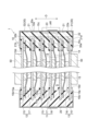
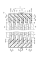
- FIG. 1 is a schematic cross-sectional view of a power storage module according to an embodiment.
- FIG. 2 is a cross-sectional view showing an enlarged area AR of FIG. 3 is a cross-sectional view showing a part of the power storage module shown in FIG. 1.
- FIG. 4 is a schematic plan view of the power storage module shown in FIG. 1.
- FIG. 5 is a schematic cross-sectional view of a power storage module according to a first modified example.
- FIG. 6 is a schematic cross-sectional view of a power storage module according to a second modification.
- FIG. 7 is a schematic cross-sectional view of a power storage module according to a third modification.
- FIG. 8 is a schematic cross-sectional view of a power storage module according to a fourth modification.
- FIG. 9 is a schematic cross-sectional view of a power storage module according to a fifth modification.
- FIG. 1 is a schematic cross-sectional view of the power storage module according to the embodiment.
- FIG. 2 is a cross-sectional view showing an enlarged area AR of FIG.
- a power storage module 1 shown in FIGS. 1 and 2 is, for example, a power storage module used in batteries of various vehicles such as forklifts, hybrid vehicles, and electric vehicles.
- the power storage module 1 is, for example, a secondary battery such as a nickel-hydrogen secondary battery or a lithium-ion secondary battery.
- the power storage module 1 may be an electric double layer capacitor or an all-solid battery. Here, the case where the electric storage module 1 is a lithium ion secondary battery is illustrated.
- the power storage module 1 includes a laminate 10 and sheet members 30 .
- the laminate 10 has a plurality of electrodes, a plurality of separators 14, a sealing portion 20, and an electrolyte (not shown).
- the plurality of electrodes includes a plurality of bipolar electrodes 11 , negative terminal electrodes 12 and positive terminal electrodes 13 .
- Each of the multiple bipolar electrodes 11 has a current collector 15 , a positive electrode active material layer 16 and a negative electrode active material layer 17 .
- the current collector 15 has, for example, a rectangular sheet shape.
- the positive electrode active material layer 16 is provided on one surface 15 a of the current collector 15 .
- the negative electrode active material layer 17 is provided on the other surface 15 b of the current collector 15 .
- the plurality of bipolar electrodes 11 are stacked such that the positive electrode active material layer 16 of one bipolar electrode 11 and the negative electrode active material layer 17 of another bipolar electrode 11 face each other.
- the direction in which the bipolar electrodes 11 are stacked is called a stacking direction D.
- One surface 15a of the current collector 15 faces one side of the stacking direction D
- the other surface 15b of the current collector 15 faces the other side of the stacking direction D.
- the positive electrode active material layer 16 and the negative electrode active material layer 17 are rectangular when viewed from the stacking direction D.
- the negative electrode active material layer 17 is one size larger than the positive electrode active material layer 16 when viewed in the stacking direction D. As shown in FIG. That is, in a plan view in the stacking direction D, the entire forming region of the positive electrode active material layer 16 is located within the forming region of the negative electrode active material layer 17 .
- the negative terminal electrode 12 has a current collector 15 and a negative electrode active material layer 17 provided on the other surface 15 b of the current collector 15 .
- the negative terminal electrode 12 does not have the positive electrode active material layer 16 and the negative electrode active material layer 17 on one surface 15 a of the current collector 15 . That is, the active material layer is not provided on the one surface 15a of the current collector 15 of the negative terminal electrode 12 .
- the negative terminal electrode 12 is stacked on the bipolar electrode 11 at one end in the stacking direction D of the stack 10 .
- the negative terminal electrode 12 is laminated on the bipolar electrode 11 such that the negative electrode active material layer 17 faces the positive electrode active material layer 16 of the bipolar electrode 11 . Therefore, one surface 15 a of the current collector 15 of the negative terminal electrode 12 faces the outside of the laminate 10 and is partly exposed outside the laminate 10 .
- the positive terminal electrode 13 has a current collector 15 and a positive electrode active material layer 16 provided on one surface 15 a of the current collector 15 .
- the positive terminal electrode 13 does not have the positive electrode active material layer 16 and the negative electrode active material layer 17 on the other surface 15 b of the current collector 15 . That is, no active material layer is provided on the other surface 15b of the current collector 15 of the positive terminal electrode 13 .
- the positive terminal electrode 13 is stacked on the bipolar electrode 11 at the other end of the stack 10 in the stacking direction D. As shown in FIG. Positive terminal electrode 13 is stacked on bipolar electrode 11 such that positive electrode active material layer 16 faces negative electrode active material layer 17 of bipolar electrode 11 . Therefore, the other surface 15 b of the current collector 15 of the positive terminal electrode 13 faces the outside of the laminate 10 and is partially exposed outside the laminate 10 .
- the separators 14 are arranged between the adjacent bipolar electrodes 11 , between the negative terminal electrode 12 and the bipolar electrode 11 , and between the positive terminal electrode 13 and the bipolar electrode 11 .
- the separator 14 is interposed between the positive electrode active material layer 16 and the negative electrode active material layer 17 .
- the separator 14 separates the positive electrode active material layer 16 and the negative electrode active material layer 17 from each other, thereby preventing short circuits due to contact between adjacent electrodes. Separator 14 is permeable to charge carriers such as lithium ions.
- the current collector 15 is a chemically inactive electrical conductor for continuing current flow through the positive electrode active material layer 16 and the negative electrode active material layer 17 during discharging or charging of the lithium ion secondary battery.
- the material of the current collector 15 is, for example, a metal material, a conductive resin material, or a conductive inorganic material.
- the conductive resin material include a resin obtained by adding a conductive filler to a conductive polymer material or a non-conductive polymer material as necessary.
- the current collector 15 may comprise multiple layers. In this case, each layer of the current collector 15 may contain the above metal material or conductive resin material.
- a coating layer may be formed on the surface of the current collector 15 .
- the coating layer may be formed by a known method such as plating or spray coating.
- the current collector 15 may have, for example, a plate shape, a foil shape (for example, a metal foil), a film shape, a mesh shape, or the like.
- metal foil include aluminum foil, copper foil, nickel foil, titanium foil, stainless steel foil, and the like.
- Stainless steel foils include, for example, SUS 304, SUS 316, SUS 301, etc. specified in JIS G 4305:2015.
- the current collector 15 may be an alloy foil or clad foil of the above metals.
- the thickness of the current collector 15 may be, for example, 1 ⁇ m to 100 ⁇ m.
- the positive electrode active material layer 16 contains a positive electrode active material capable of intercalating and deintercalating charge carriers such as lithium ions.
- positive electrode active materials include lithium composite metal oxides having a layered rock salt structure, metal oxides having a spinel structure, and polyanionic compounds. Any positive electrode active material may be used as long as it can be used in a lithium ion secondary battery.
- the positive electrode active material layer 16 may contain a plurality of positive electrode active materials.
- the positive electrode active material layer 16 contains olivine-type lithium iron phosphate (LiFePO 4 ) as a composite oxide.
- the negative electrode active material layer 17 contains a negative electrode active material capable of intercalating and deintercalating charge carriers such as lithium ions.
- the negative electrode active material may be a simple substance, an alloy, or a compound.
- Examples of negative electrode active materials include Li, carbon, and metal compounds.
- the negative electrode active material may be an element that can be alloyed with lithium, a compound thereof, or the like.
- Examples of carbon include natural graphite, artificial graphite, hard carbon (non-graphitizable carbon), soft carbon (easily graphitizable carbon), and the like.
- Examples of artificial graphite include highly oriented graphite and mesocarbon microbeads. Elements that can be alloyed with lithium include silicon (silicon), tin, and the like.
- the negative electrode active material layer 17 contains graphite as a carbonaceous material.
- Each of the positive electrode active material layer 16 and the negative electrode active material layer 17 contains a conductive aid, a binder, an electrolyte ( polymer matrices, ion-conducting polymers, electrolytes, etc.), electrolyte-supporting salts (lithium salts) to enhance ionic conductivity, and the like.
- a conductive aid is added to increase the conductivity of each electrode (bipolar electrode 11, negative terminal electrode 12, positive terminal electrode 13).
- the conductive aid is, for example, acetylene black, carbon black or graphite.
- Binders include fluorine-containing resins such as polyvinylidene fluoride, polytetrafluoroethylene, and fluororubber, thermoplastic resins such as polypropylene and polyethylene, imide resins such as polyimide and polyamideimide, alkoxysilyl group-containing resins, and acrylic acid.
- acrylic resins such as methacrylic acid, styrene-butadiene rubber (SBR), carboxymethyl cellulose, alginates such as sodium alginate and ammonium alginate, water-soluble cellulose ester crosslinked products, starch-acrylic acid graft polymers, and the like.
- SBR styrene-butadiene rubber
- alginates such as sodium alginate and ammonium alginate
- water-soluble cellulose ester crosslinked products starch-acrylic acid graft polymers, and the like.
- the solvent include water, N-methyl-2-pyrrolidone (NMP), and the like.
- the separator 14 may be, for example, a porous sheet or non-woven fabric containing a polymer that absorbs and retains the electrolyte.
- materials for the separator 14 include polypropylene, polyethylene, polyolefin, and polyester.
- Separator 14 may have a single-layer structure or a multi-layer structure.
- the multilayer structure may, for example, have ceramic layers or the like as adhesive layers or heat-resistant layers.
- the separator 14 may be impregnated with an electrolyte.
- the separator 14 may be composed of an electrolyte such as a polymer electrolyte or an inorganic electrolyte.
- the electrolyte impregnated in the separator 14 is, for example, a liquid electrolyte (electrolytic solution) containing a non-aqueous solvent and an electrolyte salt dissolved in the non-aqueous solvent, or a polymer gel electrolyte containing an electrolyte held in a polymer matrix. etc.
- the electrolyte salt may be LiClO 4 , LiAsF 6 , LiPF 6 , LiBF 4 , LiCF 3 SO 3 , LiN(FSO 2 ) 2 , LiN(CF 3 SO 2 ) 2 or the like.
- known lithium salts of may be used.
- nonaqueous solvent known solvents such as cyclic carbonates, cyclic esters, chain carbonates, chain esters, and ethers may be used. Two or more of these known solvent materials may be used in combination.
- the sealing portion 20 is formed in a frame-like shape on the periphery of the laminate 10 so as to surround the laminate 10 .
- the sealing portion 20 can be joined to each of the one surface 15a and the other surface 15b of each current collector 15 at the peripheral edge portion 15c of each current collector 15 .
- the sealing portion 20 seals each of the spaces S between the current collectors 15 adjacent to each other in the stacking direction D. As shown in FIG.
- Each space S contains an electrolyte.
- the sealing portion 20 prevents permeation of the electrolyte to the outside.
- the sealing portion 20 suppresses entry of moisture or the like into the space S from the outside of the laminate 10 .
- the sealing portion 20 prevents, for example, gas generated at each electrode due to charge/discharge reaction or the like from leaking to the outside of the power storage module 1 .
- the edge of each separator 14 is joined to the sealing portion 20 .
- the sealing portion 20 contains an insulating material. Examples of materials for the sealing portion 20 include various resin materials such as polypropylene, polyethylene, polystyrene, ABS resin, acid-modified polypropylene, acid-modified polyethylene, and acrylonitrile-styrene resin.
- the sealing portion 20 includes multiple first resin layers 21 , second resin layers 22 , and multiple third resin layers 23 .
- the first resin layer 21 is provided on each current collector 15 . Therefore, the plurality of first resin layers 21 are stacked together along the stacking direction D. As shown in FIG.
- the first resin layer 21 is frame-shaped.
- the first resin layer 21 is provided on the peripheral portion 15 c of the current collector 15 . That is, the first resin layer 21 is provided so as to extend from the one surface 15a of the current collector 15 to the other surface 15b via the end surface, and covers the peripheral edge portion 15c.
- the first resin layer 21 can be welded to at least one of the one surface 15 a and the other surface 15 b of the current collector 15 .
- Each of the plurality of third resin layers 23 is arranged so as to be interposed between the first resin layers 21 adjacent in the stacking direction D. Thereby, the plurality of third resin layers 23 hold spaces between adjacent first resin layers 21 , that is, between adjacent current collectors 15 .
- the third resin layer 23 is frame-shaped.
- the third resin layer 23 is arranged on the peripheral edge portion 15 c of the current collector 15 when viewed from the stacking direction D. As shown in FIG.
- the third resin layer 23 can be welded to at least one of the pair of first resin layers 21 adjacent in the stacking direction D. As shown in FIG. Here, the ends of the separator 14 are sandwiched and fixed between the first resin layer 21 and the third resin layer 23 .
- the second resin layer 22 is an edge weld layer formed by welding and integrating the portions of the plurality of first resin layers 21 and the plurality of third resin layers 23 that overlap in the stacking direction D.
- the second resin layer 22 has a frame-like shape surrounding the laminate 10 when viewed from the stacking direction D. As shown in FIG. In the second resin layer 22, the end portions of the plurality of adjacent first resin layers 21 and the end portions of the plurality of third resin layers 23 are welded and integrated. As a result, the space S formed between adjacent electrodes with the separator 14 interposed therebetween is sealed. An end surface 22 s of the second resin layer 22 opposite to the space S constitutes a part of the outer surface 10 s of the laminate 10 .
- the outer side surface 10s of the laminate 10 includes the end surface 22s, the first surface 21a, and the second surface 21b.
- the first surface 21 a is the outer surface in the stacking direction D of the first resin layer 21 provided on the current collector 15 of the positive terminal electrode 13 .
- the second surface 21 b is the outer surface in the stacking direction D of the first resin layer 21 provided on the current collector 15 of the negative terminal electrode 12 .
- the outer side surface 10 s of the laminate 10 is the outer side surface of the sealing portion 20 .
- the one surface 15a of the negative terminal electrode 12 facing the outside of the laminate 10 includes an exposed portion 15d exposed to the outside from the sealing portion 20 (first resin layer 21).
- the exposed portion 15d of the negative terminal electrode 12 is a portion of the current collector 15 of the negative terminal electrode 12 other than the second surface 21b (a portion that does not overlap the second surface 21b) when viewed from the stacking direction D.
- the other surface 15b of the positive terminal electrode 13 facing the outside of the laminate 10 includes an exposed portion 15d exposed to the outside from the sealing portion 20 (first resin layer 21).
- the exposed portion 15d of the positive terminal electrode 13 is a portion of the current collector 15 of the positive terminal electrode 13 other than the first surface 21a (a portion that does not overlap the first surface 21a) when viewed from the stacking direction D.
- the exposed portions 15 d provided on the negative terminal electrode 12 and the positive terminal electrode 13 respectively function as terminals for extracting current from the power storage module 1 .
- the conductive member 50 is arranged and electrically connected to these exposed portions 15d.
- Conductive member 50 is used to electrically connect a plurality of power storage modules 1 .
- the conductive member 50 can also be used as a restraining member to apply a restraining load to the laminate 10 .
- a cooling channel may be formed in the conductive member 50 .
- the laminate 10 can be cooled by circulating the cooling medium through the cooling channels formed in the conductive member 50 .
- coolers are arranged for the exposed portions 15 d of the outer surface of the current collector 15 .
- condensation water is more likely to occur around the conductive member 50 than at other portions.
- the sheet member 30 is arranged in close contact with the laminate 10 so as to cover the outer surface 10s of the laminate 10 .
- the sheet member 30 includes at least a metal layer 41 and a first insulating layer 42 laminated on the metal layer 41 .
- the sheet member 30 further includes a second insulating layer 43 laminated to the metal layer 41 on the opposite side of the first insulating layer 42 in this embodiment.
- the second insulating layer 43 is provided on the other surface of the metal layer 41 opposite to the one surface on which the first insulating layer 42 is provided. That is, the sheet member 30 is configured by sandwiching the metal layer 41 between the first insulating layer 42 and the second insulating layer 43 .
- the sheet member 30 is provided on the laminate 10 so that the first insulating layer 42 is on the outer surface 10 s side of the laminate 10 .
- the first insulating layer 42 is in contact with the outer surface 10s.
- the first insulating layer 42 may function as an adhesive layer for the outer surface 10s.
- another adhesive layer may be interposed between the sheet member 30 and the outer surface 10s.
- the first insulating layer 42 is made of insulating resin.
- the material of the first insulating layer 42 is, for example, polypropylene, polyethylene, polyamide, or the like.
- the material of the first insulating layer 42 may be selected from materials similar to those of the sealing section 20 from the viewpoint of adhesiveness to the sealing section 20 .
- the metal layer 41 is made of a material with low moisture permeability (low moisture permeability coefficient) such as aluminum foil or stainless steel foil.
- the second insulating layer 43 is made of, for example, an insulating resin.
- the material of the second insulating layer 43 is, for example, polypropylene, polyethylene, polyamide, nylon, or the like.
- the sheet member 30 is an aluminum laminate sheet, and polypropylene may be selected as the first insulating layer 42 , aluminum as the metal layer 41 , and polyethylene terephthalate as the second insulating layer 43 .
- the sheet member 30 has a portion 30a positioned on the first surface 21a on the positive terminal electrode 13 side, a portion 30s positioned on the end surface 22s, and a portion 30b positioned on the second surface 21b on the negative terminal electrode 12 side. ,including. Thereby, the sheet member 30 extends from the first surface 21a to the second surface 21b via the end surface 22s.
- the current collector 15 of the negative terminal electrode 12 includes a first area A1, a second area A2 and a third area A3.
- the first region A1 is a region where the negative electrode active material layer 17 is formed when viewed from the stacking direction D. As shown in FIG.
- the second area A2 is located outside the first area A1 when viewed from the stacking direction D, and is an area where the negative electrode active material layer 17 is not formed.
- the third area A3 is located outside the second area A2 when viewed from the stacking direction D, and is an area where the first resin layer 21 is formed.
- the current collector 15 of the positive terminal electrode 13 similarly includes a first region A1, a second region A2 and a third region A3.
- the first region A1 is a region where the positive electrode active material layer 16 is formed when viewed from the stacking direction D.
- the second area A2 is located outside the first area A1 when viewed from the stacking direction D, and is an area where the positive electrode active material layer 16 is not formed.
- the third area A3 is located outside the second area A2 when viewed from the stacking direction D, and is an area where the first resin layer 21 is formed.
- the sheet member 30 extends to the vicinity of the boundary between the third area A3 and the second area A2 so as to cover the third area A3 of the current collector 15 when viewed from the stacking direction D. .
- the sheet member 30 can be terminated so as not to reach the exposed portion 15d including the first area A1 and the second area A2.
- the end of the sheet member 30 can be arranged on the third area A3.
- the end portion of the sheet member 30 is aligned with the inner edge of the third resin layer 23 when viewed from the stacking direction D, but the end portion is not limited to this and may be positioned in the third area A3.
- 3 is a sectional view showing a part of the power storage module 1 shown in FIG. 1, but hatching is omitted.
- the sheet member 30 has at least the metal layer 41 and the , and the metal layer 41 in the portion 30b on the negative terminal electrode 12 side are electrically insulated from each other.
- the sheet member 30 includes a first portion 31 extending from the first surface 21a to the end surface 22s and a second portion 31 extending from the second surface 21b to the end surface 22s in the cross section along the stacking direction D. It is divided into parts 32 and . The first portion 31 and the second portion 32 overlap each other on the end surface 22s. Thereby, the end surface 22 s is covered with the sheet member 30 .
- the sheet member 30 is divided into a first portion 31 and a second portion 32 insulated from each other in the cross section along the stacking direction D.
- the first portion 31 and the second portion 32 include overlapping portions P that overlap each other.
- the first insulating layer 42 of the second portion 32 is in contact with the second insulating layer 43 of the first portion 31 at the overlapping portion P between the first portion 31 and the second portion 32 .
- the end of the second portion 32 overlaps the end of the first portion 31 at the overlapping portion P (on the side opposite to the laminate 10).
- the first portion 31 and the second portion 32 are electrically insulated. That is, the sheet member 30 is electrically separated in the middle. Therefore, the exposed portion 15 d of the positive terminal electrode 13 and the exposed portion 15 d of the negative terminal electrode 12 are prevented from being short-circuited via the metal layer 41 of the sheet member 30 .
- condensed water is generated around the conductive member 50 (cooler), and the condensed water causes the exposed portion 15d of the current collector 15 and the metal layer 41 of the sheet member 30 adjacent to the exposed portion 15d. Even if a conductive path is formed on both sides, the sheet member 30 on the side of the positive terminal electrode 13 and the sheet member 30 on the side of the negative terminal electrode 12 are separated from each other. A short circuit through the member 30 is suppressed.
- the second portion 32 which is arranged relatively vertically upward when the power storage module 1 is in use, is arranged relatively vertically downward. It is superimposed on the first portion 31 (on the side opposite to the laminate 10, outside). Therefore, the water flowing vertically downward is less likely to be stored in the overlapping portion P.
- an insulating tape 45 may be attached to the sheet member 30 so as to cover the overlapping portion P (so as to span from the second portion 32 to the first portion 31).
- the laminate 10 (the outer side surface 10s) has a polygonal shape with a plurality of side portions when viewed from the lamination direction D.
- the laminated body 10 has a quadrangular shape having four side portions when viewed from the lamination direction D.
- the sheet member 30 is formed in a rectangular frame shape when viewed from the stacking direction D, and consists of four portions (fourth portions) 30A, 30B, 30C, and 30D along four side portions.
- the sheet member 30 is composed of four portions 30A to 30D respectively covering the four side surfaces of the rectangular tubular outer surface 10s. That is, the sheet member 30 may be divided into a plurality of fourth portions when viewed from the stacking direction D.
- the first portion 31 and the second portion 32 of the sheet member 30 are each divided into four portions (fourth portions) 30A, 30B, 30C, and 30D along the four side portions when viewed from the stacking direction D.
- the sheet members 30 for example, the portions 30A and 30B provided on the two side portions of the laminate 10
- a portion Q is formed by overlapping each other. That is, the ends of the fourth portions that are adjacent to each other when viewed in the stacking direction D may be overlapped with each other to form an overlapping portion Q.
- the laminate 10 includes a plurality of bipolar electrodes 11 and positive terminal electrodes 13 and negative terminal electrodes 12 .
- a frame-shaped sealing portion 20 for sealing the electrolyte is provided in the space S between the current collectors 15 of each electrode.
- the sealing portion 20 is a first resin layer 21 provided on each of the current collectors 15 and a second resin layer that seals the space S by welding the outer ends of the first resin layer 21 to each other. 22.
- the outer surface 10s of the laminate 10 includes a first surface 21a, a second surface 21b, and an end surface 22s.
- the first surface 21a and the second surface 21b are outer surfaces in the stacking direction D of the first resin layer 21 provided on the positive terminal electrode 13 and the negative terminal electrode 12, respectively.
- the end surface 22 s is the outer surface of the second resin layer 22 .
- a sheet member 30 including a metal layer 41 is provided so as to cover the outer surface 10 s of the laminate 10 .
- the metal layer 41 included in the sheet member 30 has a high barrier property against moisture, intrusion of moisture into the laminate 10 is suppressed as compared with the case where the sealing body is formed only by the resin layer. .
- the sheet member 30 is provided so as to extend from the first surface 21a to the second surface 21b via the end surface 22s. For this reason, it is possible to effectively suppress the intrusion of moisture into the laminate 10 .
- the sheet member 30 is provided in close contact with the laminate 10 , a space is less likely to occur between the laminate 10 and the sheet member 30 . Therefore, intrusion of moisture can be suppressed without increasing the physical size of the power storage module 1 .
- the sheet member 30 is divided on the end surface 22s into a first portion 31 on the side of the positive terminal electrode 13 and a second portion 32 on the side of the negative terminal electrode 12 in a cross section along the stacking direction D.
- the first portion 31 and the second portion 32 are electrically insulated from each other. Therefore, although the outer surface of the current collector 15 of the positive terminal electrode 13 and the negative terminal electrode 12 includes an exposed portion 15 d exposed to the outside from the sealing portion 20 , the sheet member 30 allows the positive electrode terminal electrode 13 to and the negative terminal electrode 12 are prevented from being short-circuited.
- the power storage module 1 it is possible to suppress the intrusion of moisture into the laminate 10 while suppressing the short circuit between the positive terminal electrode 13 and the negative terminal electrode 12 .
- the sheet member 30 is divided into the first portion 31 and the second portion 32, so that when the sheet member 30 is provided in close contact with the laminate 10, each portion is laminated. It can be brought into close contact with the body 10 (it can be pasted), and workability is improved. Therefore, when the sheet member 30 is provided, wrinkles are less likely to occur in the metal layer 41 and the like.
- a sheet member containing a metal layer not divided
- the sealing portion expands and contracts due to heat, the entire sheet member tends to deform following the expansion and contraction. As a result, the metal layer, which is difficult to deform in response to the deformation, may break.
- the sheet member 30 is divided into the first portion 31 and the second portion 32, the sheet member 30 is formed so as to follow the expansion and contraction of the sealing portion 20 due to heat. Since the whole is not deformed, breakage of the metal layer 41 is suppressed.
- the first portion 31 and the second portion 32 of the divided sheet member 30 include overlapping portions P that overlap each other. For this reason, the exposed portion of the sealing portion 20 from the sheet member 30 is reduced, and intrusion of not only moisture but also air (nitrogen, oxygen, etc.) is suppressed.
- the sealing portion 20 includes a plurality of frame-shaped third resin layers 23 .
- the third resin layer 23 is arranged so as to be interposed between the first resin layers 21 adjacent in the stacking direction D.
- the second resin layer 22 seals the space S by welding the ends of the plurality of first resin layers 21 and the plurality of third resin layers 23 opposite to the space S. Therefore, the plurality of spaces S can be collectively sealed by the second resin layer 22 integrally formed along the stacking direction D, and the manufacturing thereof is easy.
- the sheet member 30 includes a second insulating layer 43 laminated on the metal layer 41 on the side opposite to the first insulating layer 42 .
- the first insulating layer 42 of the second portion 32 and the second insulating layer 43 of the first portion 31 adjacent to the second portion 32 are overlapped. Electrical insulation is formed.
- the metal layer 41 is interposed between the two layers of the first insulating layer 42 and the second insulating layer 43, so that the insulation can be easily ensured by overlapping the respective portions of the sheet member 30.
- the second portion 32 that is relatively vertically upward overlaps the first portion 31 that is relatively vertically downward at the overlapping portion P between the first portion 31 and the second portion 32. It is for this reason, in the overlapping portion P, water flowing from vertically upward to vertically downward is suppressed from being stored.
- the power storage module 1 may include an insulating tape 45 attached to the sheet member 30 so as to cover the overlapping portion P between the first portion 31 and the second portion 32 . In this case, it is possible to prevent peeling at the overlapping portion P and reliably suppress moisture intrusion.
- the current collector 15 includes a first area A1, a second area A2, and a third area A3.
- the first region A1 is a region where the positive electrode active material layer 16 and the negative electrode active material layer 17 are formed when viewed from the stacking direction D.
- the second area A2 is an area located outside the first area A1 when viewed from the stacking direction D.
- the third area A3 is located outside the second area A2 when viewed from the stacking direction D, and is an area where the first resin layer 21 is formed.
- the sheet member 30 may extend to the vicinity of the boundary between the third area A3 and the second area A2 when viewed from the stacking direction D.
- the sheet member 30 is arranged on the first resin layer 21 so that the end thereof does not reach the second area A2.
- the sealing portion 20 By covering a wide range of the sealing portion 20 with the sheet member 30, it is possible to suppress the short circuit between the positive electrode terminal electrode 13 and the negative electrode terminal electrode 12, and more effectively suppress the moisture intrusion into the laminate 10. be.
- the laminate 10 has a quadrangular shape having four side portions when viewed in the stacking direction D, and the sheet members 30 each have four side portions of the laminate 10 when viewed in the stacking direction D. It consists of four portions 30A-30D along the . Therefore, by preparing a plurality of portions 30A to 30D corresponding to each side portion of the laminate 10 when viewed from the stacking direction D, the sheet member 30 can be easily configured.
- the sheet member 30 is divided into a plurality of fourth portions (portions 30A to 30D) when viewed in the stacking direction D. Then, when viewed from the lamination direction D, the ends of the fourth portions adjacent to each other are overlapped with each other to form an overlapping portion Q. As shown in FIG. Therefore, in a configuration in which the sheet member 30 is divided into a plurality of parts when viewed from the stacking direction D, formation of conductive paths due to entry of condensed water between the parts is suppressed.
- the above embodiment describes one aspect of the power storage module according to the present disclosure.
- the power storage module according to the present disclosure may be any modification of the power storage module 1 described above. Subsequently, modifications will be described.
- FIG. 5 is a schematic cross-sectional view showing an electricity storage module 1A according to the first modified example.
- the sheet member 30 is divided into three parts, a first part 33, a second part 34 and a third part 35.
- the first portion 33 is the portion arranged on the first surface 21a
- the second portion 34 is the portion arranged on the second surface 21b.
- the first portion 33 and the second portion 34 extend to cover the entire first surface 21a and the second surface 21b, respectively.
- the third portion 35 covers the end face 22s and extends from the end face 22s so as to overlap the first portion 33 and the second portion 34 respectively.
- the third portion 35 overlaps the first portion 33 and the second portion 34 . That is, the third portion 35 overlaps the outside of the first portion 33 and the second portion 34 at the overlapping portion P between the first portion 33 and the second portion 34 and the third portion 35 . More specifically, at the overlapping portion P between the first portion 33 and the third portion 35, the end portion of the first portion 33 is stacked more than the end portion of the third portion 35 in the cross section along the stacking direction D.
- the end of the first portion 33 and the end of the third portion 35 are in contact so as to be on the body 10 side.
- the end portion of the second portion 34 is closer to the laminate 10 than the end portion of the third portion 35 in the cross section along the stacking direction D.
- the end of the second portion 34 and the end of the third portion 35 are in contact with each other.
- the outer edges of the first portion 33 and the second portion 34 need only be covered with the third portion 35 .
- the outer edges of each of the first portion 33 and the second portion 34 are sandwiched between the sealing portion 20 and the third portion 35 .
- the third portion 35 does not reach the position above the current collector 15 here, it may extend so as to reach the position above the current collector 15 .
- FIG. 6 is a schematic cross-sectional view showing a power storage module 1B according to a second modified example.
- the sheet member 30 is divided into a first portion 33, a second portion 34, and a third portion 35 similar to the power storage module 1A.
- the third portion 35 overlaps the first portion 33 and the second portion 34 at the overlapping portion P between the first portion 33 and the second portion 34 and the third portion 35, respectively. It is That is, the first portion 33 and the second portion 34 are overlapped on the outer side of the third portion 35 at the overlapping portion P between the third portion 35 and the first portion 33 and the second portion 34 .
- the end portion of the third portion 35 is stacked more than the end portion of the first portion 33 in the cross section along the stacking direction D.
- the end of the first portion 33 and the end of the third portion 35 are in contact so as to be on the body 10 side.
- the end of the third portion 35 is closer to the laminate 10 than the end of the second portion 34 in the cross section along the stacking direction D.
- the end of the second portion 34 and the end of the third portion 35 are in contact with each other.
- the outer edge of the third portion 35 may be covered with the first portion 33 and the second portion 34 respectively. In the cross section along the stacking direction D, the outer edge of the third portion 35 is sandwiched between each of the first portion 33 and the second portion 34 and the sealing portion 20 .
- the sheet member 30 has a first portion disposed on one of the first surface 21a and the second surface 21b, and an end surface 22s from the other of the first surface 21a and the second surface 21b. and a second portion extending so as to overlap the first portion. Then, the insulating tape 45 can be attached so as to cover the overlapping portion P of both of the power storage modules 1A and 1B.
- the sheet member 30 may be divided into a plurality of parts of four or more. That is, it is sufficient that the adjacent portions of the plurality of divided portions of the sheet member 30 have overlapping portions P that overlap each other.
- FIG. 7 is a schematic cross-sectional view showing an electricity storage module 1C according to the third modified example.
- the sheet member 30 includes a first portion 36 extending from the first surface 21a to cover the end surface 22s, and a second portion 36 disposed on the second surface 21b. and a second portion 37 extending toward the first portion 36 .
- the first portion 36 includes a portion 30a of the sheet member 30 located on the first surface 21a and a portion 30s located on the end surface 22s.
- Second portion 37 includes (is) portion 30b located on second surface 21b.
- it is sufficient that the second portion 37 is insulated from the first portion 36 .
- the end portion of the first portion 36 on the side of the end surface 22s is located at the corner portion R including the second surface 21b and the end surface 22s of the sealing portion 20 .
- the end portion of the second portion 37 on the side of the end face 22s is positioned at the corner portion R.
- the first portion 36 and the second portion 37 are separated so that a gap G is formed between their ends.
- the first portion 36 and the second portion 37 are insulated from each other.
- an insulating member can be arranged in the gap G.
- the insulating member may be provided so as to fill the gap G with liquid insulating resin (for example, liquid silicon) or the like.
- a protective tape such as an insulating tape or a metal laminate film (for example, a film having a layer structure similar to that of the sheet member 30) is attached so as to span the first portion 36 and the second portion 37 via the gap G. good too. Since the end face of the first portion 36 and the end face of the second portion 37 sandwiching the gap G are covered with the protective tape, the insulation between the first portion 36 and the second portion 37 due to dew condensation can be ensured more reliably.
- the gap G can be set to the minimum length within a range in which insulation can be ensured, but it may be set to a length that exposes a portion of the outer surface 10s in consideration of variations when attaching the sheet member 30 .
- the first portion 36 and the second portion 37 of the divided sheet member 30 are separated so that the gap G is formed between the ends thereof.
- An insulating member may be arranged in the gap G.
- the sheet member 30 is divided into two parts, the first part 36 and the second part 37, which are separated from each other has been described.
- the sheet member 30 may be divided into three or more portions separated by the gap G from each other.
- the position of the division (that is, the position of the gap G) can be arbitrarily set.
- the sheet member 30 is divided into a first portion extending from the first surface 21a to the middle of the end surface 22s and a second portion extending from the second surface 21b to the middle of the end surface 22s.
- the gap G may be arranged as much as possible.
- FIG. 8 is a schematic cross-sectional view of a power storage module 1D according to a fourth modified example.
- the sheet member 30 is divided into a first portion 31 and a second portion 32, similar to the power storage module 1 shown in FIG.
- the first portion 31 and the second portion 32 abut each other on the end surface 22s.
- Each of the first portion 31 and the second portion 32 extends so as to protrude away from the laminate 10 from its abutment portion.
- the first portion 31 and the second portion 32 are overlapped with each other to form an overlapping portion P at the portion protruding from the respective laminates 10 .
- the first portion 31 and the second portion 32 are electrically insulated from each other by bonding (for example, welding) the respective first insulating layers 42 to each other.
- bonding for example, welding
- FIG. 9 is a schematic cross-sectional view of a power storage module 1E according to the fifth modification.
- sheet member 30 is divided into first portion 36 and second portion 37, similar to power storage module 1C shown in FIG.
- the first portion 36 and the second portion 37 abut against each other at the corner portion R.
- Each of the first portion 36 and the second portion 37 extends so as to protrude away from the laminate 10 from its abutment portion (that is, the corner portion R).
- the first portion 36 and the second portion 37 are overlapped with each other to form an overlapping portion P at the portion protruding from the respective laminates 10 .
- the first portion 36 and the second portion 37 are electrically insulated from each other by bonding (for example, welding) the respective first insulating layers 42 to each other.
- the end of the second portion 37 is located outside the end (end surface 22s) of the first surface 21a.
- the end portion of the first portion 36 is located closer to the laminate 10 than the end portion of the second portion 37 is.
- the first portion 36 and the second portion 37 extend in a direction intersecting the stacking direction D at the overlapping portion P.
- the first portion 36 and the second portion 37 may be extended along the stacking direction D by being bent inward in the direction D. As shown in FIG.
- the sheet member 30 has three layers, the first insulating layer 42, the metal layer 41, and the second insulating layer 43. From the viewpoint of suppressing short circuits and moisture intrusion, the sheet member 30 should have at least the metal layer 41 and the first insulating layer 42 . Alternatively, sheet member 30 may have four or more layers including metal layer 41 and first insulating layer 42 .
- the sheet members 30 are provided along each of the four side portions of the laminate 10 when viewed from the stacking direction D.
- the sheet member 30 may be provided along at least one of the four side portions of the laminate 10 when viewed from the stacking direction D.
- the sheet member 30 is not limited to the four portions 30A to 30D covering the four side surfaces of the square tubular outer surface 10s. It is only necessary to have a portion that covers one side surface.
Landscapes
- Chemical & Material Sciences (AREA)
- Chemical Kinetics & Catalysis (AREA)
- Electrochemistry (AREA)
- General Chemical & Material Sciences (AREA)
- Engineering & Computer Science (AREA)
- Manufacturing & Machinery (AREA)
- Power Engineering (AREA)
- Microelectronics & Electronic Packaging (AREA)
- Sealing Battery Cases Or Jackets (AREA)
Priority Applications (2)
| Application Number | Priority Date | Filing Date | Title |
|---|---|---|---|
| JP2023572389A JP7711772B2 (ja) | 2022-01-07 | 2022-12-07 | 蓄電モジュール |
| CN202280087615.5A CN118525402A (zh) | 2022-01-07 | 2022-12-07 | 蓄电模块 |
Applications Claiming Priority (2)
| Application Number | Priority Date | Filing Date | Title |
|---|---|---|---|
| JP2022001467 | 2022-01-07 | ||
| JP2022-001467 | 2022-01-07 |
Publications (1)
| Publication Number | Publication Date |
|---|---|
| WO2023132181A1 true WO2023132181A1 (ja) | 2023-07-13 |
Family
ID=87073498
Family Applications (1)
| Application Number | Title | Priority Date | Filing Date |
|---|---|---|---|
| PCT/JP2022/045162 Ceased WO2023132181A1 (ja) | 2022-01-07 | 2022-12-07 | 蓄電モジュール |
Country Status (3)
| Country | Link |
|---|---|
| JP (1) | JP7711772B2 (https=) |
| CN (1) | CN118525402A (https=) |
| WO (1) | WO2023132181A1 (https=) |
Cited By (4)
| Publication number | Priority date | Publication date | Assignee | Title |
|---|---|---|---|---|
| JPWO2024034403A1 (https=) * | 2022-08-12 | 2024-02-15 | ||
| WO2025229817A1 (ja) * | 2024-04-30 | 2025-11-06 | 株式会社豊田自動織機 | 蓄電装置 |
| WO2025253930A1 (ja) * | 2024-06-03 | 2025-12-11 | 株式会社豊田自動織機 | 蓄電装置 |
| WO2025253932A1 (ja) * | 2024-06-03 | 2025-12-11 | 株式会社豊田自動織機 | 蓄電装置 |
Citations (6)
| Publication number | Priority date | Publication date | Assignee | Title |
|---|---|---|---|---|
| JP2005276486A (ja) * | 2004-03-23 | 2005-10-06 | Nissan Motor Co Ltd | 積層型電池、組電池および車両 |
| WO2006062204A1 (ja) * | 2004-12-10 | 2006-06-15 | Nissan Motor Co., Ltd. | バイポーラ電池 |
| JP2020030949A (ja) * | 2018-08-22 | 2020-02-27 | 株式会社豊田自動織機 | 蓄電モジュール |
| JP2020057554A (ja) * | 2018-10-03 | 2020-04-09 | 株式会社豊田自動織機 | 蓄電モジュール |
| JP2020144996A (ja) * | 2019-03-04 | 2020-09-10 | 積水化学工業株式会社 | 蓄電素子および蓄電素子の製造方法 |
| JP2021177478A (ja) * | 2020-04-30 | 2021-11-11 | 株式会社豊田自動織機 | 蓄電セル、蓄電装置及び蓄電装置の製造方法 |
-
2022
- 2022-12-07 WO PCT/JP2022/045162 patent/WO2023132181A1/ja not_active Ceased
- 2022-12-07 JP JP2023572389A patent/JP7711772B2/ja active Active
- 2022-12-07 CN CN202280087615.5A patent/CN118525402A/zh active Pending
Patent Citations (6)
| Publication number | Priority date | Publication date | Assignee | Title |
|---|---|---|---|---|
| JP2005276486A (ja) * | 2004-03-23 | 2005-10-06 | Nissan Motor Co Ltd | 積層型電池、組電池および車両 |
| WO2006062204A1 (ja) * | 2004-12-10 | 2006-06-15 | Nissan Motor Co., Ltd. | バイポーラ電池 |
| JP2020030949A (ja) * | 2018-08-22 | 2020-02-27 | 株式会社豊田自動織機 | 蓄電モジュール |
| JP2020057554A (ja) * | 2018-10-03 | 2020-04-09 | 株式会社豊田自動織機 | 蓄電モジュール |
| JP2020144996A (ja) * | 2019-03-04 | 2020-09-10 | 積水化学工業株式会社 | 蓄電素子および蓄電素子の製造方法 |
| JP2021177478A (ja) * | 2020-04-30 | 2021-11-11 | 株式会社豊田自動織機 | 蓄電セル、蓄電装置及び蓄電装置の製造方法 |
Cited By (7)
| Publication number | Priority date | Publication date | Assignee | Title |
|---|---|---|---|---|
| JPWO2024034403A1 (https=) * | 2022-08-12 | 2024-02-15 | ||
| WO2024034403A1 (ja) * | 2022-08-12 | 2024-02-15 | 株式会社豊田自動織機 | 蓄電モジュール |
| JP7772232B2 (ja) | 2022-08-12 | 2025-11-18 | 株式会社豊田自動織機 | 蓄電モジュール |
| EP4553936A4 (en) * | 2022-08-12 | 2025-11-19 | Toyota Jidoshokki Kk | ELECTRICAL ENERGY STORAGE MODULE |
| WO2025229817A1 (ja) * | 2024-04-30 | 2025-11-06 | 株式会社豊田自動織機 | 蓄電装置 |
| WO2025253930A1 (ja) * | 2024-06-03 | 2025-12-11 | 株式会社豊田自動織機 | 蓄電装置 |
| WO2025253932A1 (ja) * | 2024-06-03 | 2025-12-11 | 株式会社豊田自動織機 | 蓄電装置 |
Also Published As
| Publication number | Publication date |
|---|---|
| JP7711772B2 (ja) | 2025-07-23 |
| CN118525402A (zh) | 2024-08-20 |
| JPWO2023132181A1 (https=) | 2023-07-13 |
Similar Documents
| Publication | Publication Date | Title |
|---|---|---|
| JP7711772B2 (ja) | 蓄電モジュール | |
| US20260074398A1 (en) | Electric power storage module | |
| JP2023087348A (ja) | 蓄電装置の製造方法及び蓄電装置 | |
| JP7468233B2 (ja) | 蓄電モジュール | |
| WO2022102286A1 (ja) | 蓄電モジュール | |
| JP2022016904A (ja) | 蓄電モジュール | |
| US20260058339A1 (en) | Method for manufacturing power storage module, and power storage module | |
| US20250105452A1 (en) | Electric power storage module | |
| JP7810095B2 (ja) | 蓄電モジュール | |
| KR20230125820A (ko) | 축전 셀 및 축전 장치 | |
| JP2024120645A (ja) | 蓄電モジュール製造方法、及び、蓄電モジュール | |
| JP2024088116A (ja) | 蓄電モジュール製造方法、及び、蓄電モジュール | |
| US20250219206A1 (en) | Power storage module and manufacturing method of power storage module | |
| JP2021197279A (ja) | 蓄電セル及び蓄電装置 | |
| JP7772232B2 (ja) | 蓄電モジュール | |
| JP7444029B2 (ja) | 蓄電セル及び蓄電装置 | |
| JP7647886B2 (ja) | 蓄電装置 | |
| WO2025115451A1 (ja) | 蓄電モジュール | |
| WO2025053143A1 (ja) | 蓄電モジュール | |
| KR20260061240A (ko) | 축전 모듈 | |
| JP2023046589A (ja) | 蓄電装置 | |
| JP2022064585A (ja) | 蓄電装置 | |
| JP2022064371A (ja) | 蓄電セル及び蓄電装置 | |
| JP2022080684A (ja) | 蓄電モジュール | |
| JP2022076709A (ja) | 蓄電装置 |
Legal Events
| Date | Code | Title | Description |
|---|---|---|---|
| 121 | Ep: the epo has been informed by wipo that ep was designated in this application |
Ref document number: 22918767 Country of ref document: EP Kind code of ref document: A1 |
|
| WWE | Wipo information: entry into national phase |
Ref document number: 202280087615.5 Country of ref document: CN |
|
| ENP | Entry into the national phase |
Ref document number: 2023572389 Country of ref document: JP Kind code of ref document: A |
|
| NENP | Non-entry into the national phase |
Ref country code: DE |
|
| 122 | Ep: pct application non-entry in european phase |
Ref document number: 22918767 Country of ref document: EP Kind code of ref document: A1 |