WO2023132047A1 - 静止誘導器ユニット - Google Patents
静止誘導器ユニット Download PDFInfo
- Publication number
- WO2023132047A1 WO2023132047A1 PCT/JP2022/000315 JP2022000315W WO2023132047A1 WO 2023132047 A1 WO2023132047 A1 WO 2023132047A1 JP 2022000315 W JP2022000315 W JP 2022000315W WO 2023132047 A1 WO2023132047 A1 WO 2023132047A1
- Authority
- WO
- WIPO (PCT)
- Prior art keywords
- chamber
- stationary
- stationary inductor
- duct
- heat radiation
- Prior art date
- Legal status (The legal status is an assumption and is not a legal conclusion. Google has not performed a legal analysis and makes no representation as to the accuracy of the status listed.)
- Ceased
Links
Images




Classifications
-
- H—ELECTRICITY
- H01—ELECTRIC ELEMENTS
- H01F—MAGNETS; INDUCTANCES; TRANSFORMERS; SELECTION OF MATERIALS FOR THEIR MAGNETIC PROPERTIES
- H01F27/00—Details of transformers or inductances, in general
- H01F27/08—Cooling; Ventilating
-
- H—ELECTRICITY
- H01—ELECTRIC ELEMENTS
- H01F—MAGNETS; INDUCTANCES; TRANSFORMERS; SELECTION OF MATERIALS FOR THEIR MAGNETIC PROPERTIES
- H01F27/00—Details of transformers or inductances, in general
- H01F27/08—Cooling; Ventilating
- H01F27/10—Liquid cooling
- H01F27/12—Oil cooling
-
- H—ELECTRICITY
- H01—ELECTRIC ELEMENTS
- H01F—MAGNETS; INDUCTANCES; TRANSFORMERS; SELECTION OF MATERIALS FOR THEIR MAGNETIC PROPERTIES
- H01F27/00—Details of transformers or inductances, in general
- H01F27/08—Cooling; Ventilating
- H01F27/20—Cooling by special gases or non-ambient air
Definitions
- Embodiments of the present invention relate to stationary inductor units.
- a stationary inductor unit has a stationary inductor and a radiator.
- a static inductor has a transformer and an insulating medium.
- a radiator is connected to the stationary inductor and has an insulating medium flowing through it. A radiator cools the insulating medium.
- substations are installed indoors due to overcrowding due to population growth in urban areas.
- a stationary inductor unit When a stationary inductor unit is installed in the confined space of an indoor or underground substation, the cooling performance of the insulating medium may be degraded.
- a stationary inductor unit that can suppress deterioration in cooling performance of an insulating medium.
- JP 2017-180182 A JP-A-1-312810
- the problem to be solved by the present invention is to provide a stationary inductor unit that can suppress deterioration in cooling performance of an insulating medium.
- the stationary inductor unit of the embodiment has a stationary inductor, a radiator, a heat radiation duct, and a regulating member.
- a stationary inductor includes an insulating medium.
- a radiator is connected to the stationary inductor and has an insulating medium flowing through it.
- the heat radiating duct houses the radiator and has an upper opening and a lower opening.
- the regulating member regulates air circulation between the upper opening and the lower opening via the outside of the heat radiation duct in the accommodation chamber for the stationary inductor and the heat radiation duct.
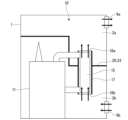
- FIG. 2 is a schematic configuration diagram of the stationary inducer unit of the first embodiment; The schematic block diagram of the stationary inducer unit of the modification of 1st Embodiment. The schematic block diagram of the stationary inducer unit of 2nd Embodiment. The schematic block diagram of the stationary inducer unit of 3rd Embodiment. The schematic block diagram of the stationary inducer unit of 4th Embodiment. The schematic block diagram of the stationary inducer unit of the modification of 4th Embodiment.
- FIG. 1 is a schematic configuration diagram of a stationary inducer unit of the first embodiment.
- the stationary inductor unit 10 has a stationary inductor 11 , a radiator 15 and a heat dissipation duct 17 .
- the stationary inductor 11 contains a transformer and an insulating medium (both not shown) inside a tank.
- a transformer has an iron core (core) and windings (coils).
- the insulating medium is insulating oil, insulating gas, or the like.
- the insulating gas is SF6 or the like, and the insulating oil is mineral oil or ester oil or the like.
- An insulating medium is filled around the transformer. The transformer heats up as the windings are energized. The heat in the transformer is transferred to the surrounding insulating medium.
- a radiator (radiator) 15 has a flow path through which an insulating medium flows.
- the channel is formed in a flat plate shape.
- a plurality of flat plate-like flow paths are arranged horizontally side by side.
- the radiator 15 is connected to the stationary inductor 11 by pipes 13a and 13b.
- the pipes 13a and 13b are an upper pipe 13a and a lower pipe 13b.
- the insulating medium heated by the stationary inductor 11 flows into the radiator 15 through the upper pipe 13a.
- the insulating medium flowing through the radiator 15 exchanges heat with the surrounding air, radiates heat, and is cooled.
- the cooled insulating medium returns to the stationary inductor 11 through the lower pipe 13b.
- a heat radiation duct (ventilation duct) 17 surrounds the radiator 15 in the horizontal direction.
- the heat radiation duct 17 has an upper opening 18a and a lower opening 18b.
- the stationary inducer unit 10 is placed inside the containment chamber 1.
- the containment chamber 1 has an upper ventilation port 6a and a lower ventilation port 6b.
- the upper ventilation port 6 a is arranged in the upper part of the storage room 1 and the lower ventilation port 6 b is arranged in the lower part of the storage room 1 . Ventilation openings 6a and 6b communicate the inside and outside of storage room 1 with each other.
- the cold air outside the containment room 1 flows into the containment room 1 through the lower ventilation port 6b. Cool air flows into the heat radiation duct 17 from the lower opening 18b. The cold air flowing through the heat radiation duct 17 exchanges heat with the insulating medium flowing through the radiator 15, absorbs heat, and changes into warm air. The warm air flows into the housing chamber 1 through the upper opening 18 a of the heat radiation duct 17 . The warm air flows out of the storage room 1 through the upper ventilation port 6a. Air blowers may be attached to the ventilation openings 6a and 6b.
- the stationary inducer unit 10 is housed inside the narrow housing chamber 1 in order to save space.
- part of the warm air that has flowed out of the upper opening 18a of the heat radiation duct 17 stays inside the storage room 1 without flowing out of the storage room 1 through the upper ventilation port 6a.
- Warm air descends outside the heat radiation duct 17 along the side wall of the housing chamber 1 .
- Warm air flows into the heat radiation duct 17 from the lower opening 18b. That is, warm air circulates inside the storage chamber 1 .
- the heat exchange efficiency of the radiator 15 is lowered, and the cooling performance of the insulating medium of the stationary inductor unit 10 is lowered.
- the stationary inducer unit 10 has a regulating member 20.
- the regulating member 20 regulates circulation of warm air inside the storage chamber 1 .
- the regulating member 20 regulates the flow of air between the upper opening 18 a and the lower opening 18 b via the outside of the heat radiation duct 17 inside the housing chamber 1 .
- the stationary inducer unit 10 has an upper connection duct 21 as a regulating member 20.
- the upper connection duct 21 connects the upper opening 18 a of the heat radiation duct 17 and the upper ventilation port 6 a of the storage chamber 1 .
- the warm air flowing out from the upper opening 18a passes through the upper connection duct 21 and flows out of the storage room 1 from the upper ventilation port 6a.
- the upper connection duct 21 regulates the flow of air between the upper opening 18 a and the lower opening 18 b via the outside of the heat radiation duct 17 inside the housing chamber 1 .
- Warm air does not flow into the heat radiation duct 17 from the lower opening 18b. Instead, cold air that has flowed into the housing chamber 1 through the lower ventilation port 6b flows into the heat radiation duct 17 through the lower opening 18b.
- the heat exchange efficiency of the radiator 15 is improved, and the deterioration of the cooling performance of the insulating medium of the stationary inductor unit 10 is suppressed.
- the static inducer unit 10 can be accommodated inside the narrow accommodation chamber 1 .
- the size of the containment chamber 1 can be reduced to the extent of the physical size of the stationary inducer unit 10 .
- the stationary inducer unit 10 may have a lower connection duct (not shown) as the regulating member 20 instead of the upper connection duct 21 .
- the lower connection duct connects the lower ventilation port 6b of the storage chamber 1 and the lower opening 18b of the heat radiation duct 17. As shown in FIG. In this case, only cool air that has flowed in from the lower ventilation port 6b flows into the lower opening 18b of the heat radiation duct 17. As shown in FIG.
- the lower connection duct regulates air circulation between the upper opening 18 a and the lower opening 18 b via the outside of the heat radiation duct 17 inside the storage chamber 1 . Warm air flowing out from the upper opening 18a of the heat radiation duct 17 does not flow into the lower opening 18b.
- the stationary inducer unit 10 may have both an upper connecting duct 21 and a lower connecting duct as the restricting member 20 .
- FIG. 2 is a schematic configuration diagram of a stationary inducer unit of a modified example of the first embodiment.
- the stationary inductor unit 10 of the modification differs from the first embodiment in that it has a blower (fan, cooling fan) 30 .
- the blower 30 is attached to the lower opening 18 b of the heat radiation duct 17 .
- the blower 30 blows air into the heat radiation duct 17 from the lower opening 18b. Cool air that has flowed into the storage chamber 1 from the lower ventilation port 6 b is promoted to flow into the heat radiation duct 17 . This improves the cooling performance of the insulating medium of the stationary inductor unit 10 .
- FIG. 3 is a schematic configuration diagram of a stationary inducer unit of the second embodiment.
- a stationary inducer unit 10 of the second embodiment differs from the first embodiment in that it has a closing plate 23 as a regulating member 20 . Descriptions of the second embodiment that are the same as those of the first embodiment may be omitted.
- the closing plate 23 divides the interior of the housing chamber 1 into an upper chamber 2a and a lower chamber 2b.
- Upper chamber 2 a includes upper opening 18 a of heat dissipation duct 17 and upper ventilation port 6 a of housing chamber 1 .
- the lower chamber 2b includes the lower opening 18b of the heat radiation duct 17 and the lower ventilation port 6b of the accommodation chamber 1.
- the lower chamber 2b further contains a stationary inductor 11.
- the closing plate 23 is arranged outside the heat radiation duct 17 and in the middle portion of the heat radiation duct 17 in the vertical direction.
- the closing plate 23 regulates the flow of air between the upper opening 18 a and the lower opening 18 b via the outside of the heat radiation duct 17 inside the housing chamber 1 .
- a closing plate 23 regulates the descent of warm air into the lower chamber 2b.
- Warm air does not flow into the heat radiation duct 17 through the lower opening 18b included in the lower chamber 2b.
- Cool air that has flowed into the lower chamber 2b from the lower ventilation port 6b flows into the heat radiation duct 17 from the lower opening 18b. Thereby, the heat exchange efficiency of the radiator 15 is improved, and the deterioration of the cooling performance of the insulating medium of the stationary inductor unit 10 is suppressed.
- a blower may be attached to the lower opening 18b of the heat radiation duct 17 of the stationary inductor unit 10. This improves the cooling performance of the insulating medium of the stationary inductor unit 10 .
- FIG. 4 is a schematic configuration diagram of a stationary inducer unit of the third embodiment.
- a stationary inducer unit 10 of the third embodiment differs from the first embodiment in that it has a partition wall 25 .
- a description of the third embodiment that is the same as that of the first embodiment may be omitted.
- the stationary inductor 11 generates heat during operation.
- the heat of the stationary inductor 11 is transferred to the surrounding air.
- the stationary inducer unit 10 may be housed inside a narrow housing chamber 1 . In this case, warm air around the stationary inductor 11 may flow into the heat radiation duct 17 through the lower opening 18b. As a result, the heat exchange efficiency of the radiator 15 is lowered, and the cooling performance of the insulating medium of the stationary inductor unit 10 is lowered.
- the stationary inductor unit 10 has a partition wall 25.
- the partition wall 25 partitions the interior of the storage chamber 1 into a first chamber 3c and a second chamber 3d.
- the first chamber 3 c includes a radiator 15 and a heat radiation duct 17 .
- a blower 30 is attached to the lower opening 18 b of the heat radiation duct 17 .
- the second chamber 3 d contains a stationary inducer 11 .
- the partition wall 25 regulates air circulation between the first chamber 3c and the second chamber 3d.
- a partition wall 25 regulates movement of warm air from the second chamber 3 d containing the stationary inductor 11 to the first chamber 3 c containing the heat radiation duct 17 .
- Warm air around the stationary inductor 11 does not flow into the lower opening 18b of the heat radiation duct 17 .
- deterioration in the cooling performance of the insulating medium of the stationary inductor unit 10 is suppressed.
- the first chamber 3c includes the above-described upper ventilation port 6a and lower ventilation port 6b (hereinafter sometimes referred to as the first upper ventilation port 6a and the first lower ventilation port 6b).
- the second chamber 3d includes a second upper ventilation opening 7a and a second lower ventilation opening 7b.
- the second upper ventilation port 7a is arranged above the second chamber 3d, and the second lower ventilation port 7b is arranged below the second chamber 3d. Ventilation ports 7a and 7b communicate the inside of the second chamber 3d and the outside of the storage chamber 1. As shown in FIG.
- the warm air around the stationary inductor 11 flows out of the containment chamber 1 through the second upper ventilation port 7a. Cool air outside the housing chamber 1 flows into the second chamber 3d through the second lower ventilation port 7b. Thereby, the temperature rise of the stationary inductor 11 in the second chamber 3d is suppressed.
- a blower may be attached to the ventilation openings 7a and 7b.
- FIG. 5 is a schematic configuration diagram of a stationary inducer unit of the fourth embodiment.
- a stationary inducer unit 10 of the fourth embodiment differs from the second and third embodiments in that it has a closing plate 23 as a regulating member 20 in addition to the partition wall 25 . Descriptions of the fourth embodiment that are the same as those of the second and third embodiments may be omitted.
- the closing plate 23 divides the interior of the first chamber 3c into an upper chamber 2a and a lower chamber 2b.
- the upper chamber 2a includes the upper opening 18a of the heat radiation duct 17 and the first upper ventilation port 6a of the first chamber 3c.
- the lower chamber 2b includes the lower opening 18b of the heat dissipation duct 17 and the first lower ventilation port 6b of the first chamber 3c.
- the closing plate 23 regulates air flow between the upper opening 18a and the lower opening 18b through the outside of the heat radiation duct 17 inside the first chamber 3c. Warm air that has flowed into the upper chamber 2a through the upper opening 18a does not flow into the heat radiation duct 17 through the lower opening 18b of the lower chamber 2b.
- the partition wall 25 regulates air circulation between the first chamber 3c and the second chamber 3d. Warm air around the stationary inductor 11 in the second chamber 3d does not flow into the heat radiation duct 17 in the first chamber 3c. As a result, deterioration in the cooling performance of the insulating medium of the stationary inductor unit 10 is suppressed.
- the stationary inducer unit 10 of the fourth embodiment has a closing plate 23 as the regulating member 20 in addition to the partition wall 25 .
- the stationary inducer unit 10 may have one or both of the upper connecting duct 21 and the lower connecting duct as the restricting member 20 in addition to the partition wall 25 .
- FIG. 6 is a schematic configuration diagram of a stationary inducer unit of a modified example of the fourth embodiment.
- the stationary inductor unit 10 of the modified example differs from the fourth embodiment in that it has a blower 30 .
- the blower 30 is attached to the lower opening 18 b of the heat radiation duct 17 .
- the blower 30 blows air into the heat radiation duct 17 from the lower opening 18b. Cool air that has flowed into the lower chamber 2 b from the first lower ventilation port 6 b is promoted to flow into the heat radiation duct 17 . This improves the cooling performance of the insulating medium of the stationary inductor unit 10 .
- a regulating member 20 that regulates air circulation between the upper opening 18a and the lower opening 18b via the outside of the heat radiation duct 17 inside the storage chamber 1.
- SYMBOLS 1 Storage chamber, 2a... Upper chamber, 2b... Lower chamber, 6a... Upper ventilation port, 6b... Lower ventilation port, 10... Stationary inductor unit, 11... Stationary inductor, 15... Radiator, 17... Radiation duct, 18a... Upper opening, 18b... Lower opening, 20... Regulating member, 21... Upper connecting duct (connecting duct), 23... Closing plate, 25... Partition wall, 30... Blower.
Landscapes
- Engineering & Computer Science (AREA)
- Power Engineering (AREA)
- Cooling Or The Like Of Electrical Apparatus (AREA)
- Transformer Cooling (AREA)
Priority Applications (2)
| Application Number | Priority Date | Filing Date | Title |
|---|---|---|---|
| PCT/JP2022/000315 WO2023132047A1 (ja) | 2022-01-07 | 2022-01-07 | 静止誘導器ユニット |
| JP2023572305A JP7600438B2 (ja) | 2022-01-07 | 2022-01-07 | 静止誘導器ユニット |
Applications Claiming Priority (1)
| Application Number | Priority Date | Filing Date | Title |
|---|---|---|---|
| PCT/JP2022/000315 WO2023132047A1 (ja) | 2022-01-07 | 2022-01-07 | 静止誘導器ユニット |
Publications (1)
| Publication Number | Publication Date |
|---|---|
| WO2023132047A1 true WO2023132047A1 (ja) | 2023-07-13 |
Family
ID=87073463
Family Applications (1)
| Application Number | Title | Priority Date | Filing Date |
|---|---|---|---|
| PCT/JP2022/000315 Ceased WO2023132047A1 (ja) | 2022-01-07 | 2022-01-07 | 静止誘導器ユニット |
Country Status (2)
| Country | Link |
|---|---|
| JP (1) | JP7600438B2 (https=) |
| WO (1) | WO2023132047A1 (https=) |
Citations (10)
| Publication number | Priority date | Publication date | Assignee | Title |
|---|---|---|---|---|
| JPS4739528Y1 (https=) * | 1968-10-28 | 1972-11-30 | ||
| JPS5229413U (https=) * | 1975-08-22 | 1977-03-01 | ||
| JPH032616U (https=) * | 1989-05-30 | 1991-01-11 | ||
| JPH062648U (ja) * | 1992-06-22 | 1994-01-14 | 東芝エフエーシステムエンジニアリング株式会社 | 耐塩形変圧器 |
| JPH11283843A (ja) * | 1998-03-30 | 1999-10-15 | Daihen Corp | 屋内設置変圧器の冷却装置 |
| JPH11283844A (ja) * | 1998-03-30 | 1999-10-15 | Daihen Corp | 屋内設置変圧器の冷却装置 |
| JP2009081171A (ja) * | 2007-09-25 | 2009-04-16 | Mitsubishi Electric Corp | キュービクルの放熱構造 |
| JP2013214624A (ja) * | 2012-04-02 | 2013-10-17 | Mitsubishi Electric Corp | 電気機器の冷却装置 |
| JP2014117121A (ja) * | 2012-12-12 | 2014-06-26 | Toshiba Corp | 冷却装置及び冷却方法並びに鉄道車両 |
| JP2016213211A (ja) * | 2013-09-06 | 2016-12-15 | 株式会社日立製作所 | 変圧器 |
-
2022
- 2022-01-07 WO PCT/JP2022/000315 patent/WO2023132047A1/ja not_active Ceased
- 2022-01-07 JP JP2023572305A patent/JP7600438B2/ja active Active
Patent Citations (10)
| Publication number | Priority date | Publication date | Assignee | Title |
|---|---|---|---|---|
| JPS4739528Y1 (https=) * | 1968-10-28 | 1972-11-30 | ||
| JPS5229413U (https=) * | 1975-08-22 | 1977-03-01 | ||
| JPH032616U (https=) * | 1989-05-30 | 1991-01-11 | ||
| JPH062648U (ja) * | 1992-06-22 | 1994-01-14 | 東芝エフエーシステムエンジニアリング株式会社 | 耐塩形変圧器 |
| JPH11283843A (ja) * | 1998-03-30 | 1999-10-15 | Daihen Corp | 屋内設置変圧器の冷却装置 |
| JPH11283844A (ja) * | 1998-03-30 | 1999-10-15 | Daihen Corp | 屋内設置変圧器の冷却装置 |
| JP2009081171A (ja) * | 2007-09-25 | 2009-04-16 | Mitsubishi Electric Corp | キュービクルの放熱構造 |
| JP2013214624A (ja) * | 2012-04-02 | 2013-10-17 | Mitsubishi Electric Corp | 電気機器の冷却装置 |
| JP2014117121A (ja) * | 2012-12-12 | 2014-06-26 | Toshiba Corp | 冷却装置及び冷却方法並びに鉄道車両 |
| JP2016213211A (ja) * | 2013-09-06 | 2016-12-15 | 株式会社日立製作所 | 変圧器 |
Also Published As
| Publication number | Publication date |
|---|---|
| JP7600438B2 (ja) | 2024-12-16 |
| JPWO2023132047A1 (https=) | 2023-07-13 |
Similar Documents
| Publication | Publication Date | Title |
|---|---|---|
| KR102323608B1 (ko) | 유입 변압기 | |
| JPWO2008007513A1 (ja) | 車両用変圧器 | |
| KR102163167B1 (ko) | 폐열을 이용한 난방 시스템 | |
| KR101538093B1 (ko) | 유입변압기 | |
| KR960014519B1 (ko) | 가스절연식 전기장치 | |
| CN114785030A (zh) | 一种散热机壳、电机和空压机 | |
| JP2009231441A (ja) | 油入変圧器装置 | |
| JP2009081171A (ja) | キュービクルの放熱構造 | |
| WO2023132047A1 (ja) | 静止誘導器ユニット | |
| JP7228377B2 (ja) | 静止誘導電器 | |
| CN111403151B (zh) | 一种水循环冷却的干式变压器 | |
| KR101679340B1 (ko) | 유입변압기 | |
| KR102144666B1 (ko) | 스테이터의 밀폐 냉각을 통해 고효율 냉각이 가능한 터보 모터 | |
| JP2019066058A (ja) | 室内ユニット、及びこれを備えた空気調和機 | |
| JP6946218B2 (ja) | 静止誘導器 | |
| JP6796023B2 (ja) | 静止誘導機器及び静止誘導機器用の放熱器 | |
| JP6594588B1 (ja) | 静止誘導機器 | |
| CN223842724U (zh) | 一种干式配电变压器 | |
| JP2018195667A (ja) | 油入静止誘導機器 | |
| JP2012119398A (ja) | ガス絶縁誘導装置 | |
| KR101099190B1 (ko) | 유입 변압기 | |
| KR20170000937U (ko) | 유입식 변압기 | |
| JPH04354312A (ja) | ガス絶縁変圧器 | |
| CN120833956B (zh) | 一种具有蜂窝散热结构的油浸式变压器 | |
| CN218214920U (zh) | 散热装置 |
Legal Events
| Date | Code | Title | Description |
|---|---|---|---|
| 121 | Ep: the epo has been informed by wipo that ep was designated in this application |
Ref document number: 22918636 Country of ref document: EP Kind code of ref document: A1 |
|
| ENP | Entry into the national phase |
Ref document number: 2023572305 Country of ref document: JP Kind code of ref document: A |
|
| NENP | Non-entry into the national phase |
Ref country code: DE |
|
| 122 | Ep: pct application non-entry in european phase |
Ref document number: 22918636 Country of ref document: EP Kind code of ref document: A1 |