WO2023127389A1 - 繊維強化複合材料の製造方法、繊維強化複合材料、及び、成形品の製造方法 - Google Patents
繊維強化複合材料の製造方法、繊維強化複合材料、及び、成形品の製造方法 Download PDFInfo
- Publication number
- WO2023127389A1 WO2023127389A1 PCT/JP2022/044316 JP2022044316W WO2023127389A1 WO 2023127389 A1 WO2023127389 A1 WO 2023127389A1 JP 2022044316 W JP2022044316 W JP 2022044316W WO 2023127389 A1 WO2023127389 A1 WO 2023127389A1
- Authority
- WO
- WIPO (PCT)
- Prior art keywords
- fiber
- reinforced composite
- composite material
- roll
- impregnation
- Prior art date
Links
- 239000000463 material Substances 0.000 title claims abstract description 69
- 239000003733 fiber-reinforced composite Substances 0.000 title claims abstract description 60
- 238000004519 manufacturing process Methods 0.000 title claims abstract description 48
- 238000005470 impregnation Methods 0.000 claims abstract description 88
- 239000011342 resin composition Substances 0.000 claims abstract description 35
- 239000012783 reinforcing fiber Substances 0.000 claims abstract description 33
- 238000010438 heat treatment Methods 0.000 claims description 8
- 238000003825 pressing Methods 0.000 claims description 6
- 238000010030 laminating Methods 0.000 claims description 3
- 238000000034 method Methods 0.000 abstract description 16
- 229920005989 resin Polymers 0.000 description 41
- 239000011347 resin Substances 0.000 description 41
- 229920000049 Carbon (fiber) Polymers 0.000 description 31
- 239000004917 carbon fiber Substances 0.000 description 31
- 239000003822 epoxy resin Substances 0.000 description 30
- 229920000647 polyepoxide Polymers 0.000 description 30
- 239000003677 Sheet moulding compound Substances 0.000 description 25
- VNWKTOKETHGBQD-UHFFFAOYSA-N methane Chemical compound C VNWKTOKETHGBQD-UHFFFAOYSA-N 0.000 description 25
- -1 phenoxyethyl Chemical group 0.000 description 25
- 239000000047 product Substances 0.000 description 25
- NIXOWILDQLNWCW-UHFFFAOYSA-M Acrylate Chemical compound [O-]C(=O)C=C NIXOWILDQLNWCW-UHFFFAOYSA-M 0.000 description 18
- 239000012778 molding material Substances 0.000 description 15
- IISBACLAFKSPIT-UHFFFAOYSA-N bisphenol A Chemical compound C=1C=C(O)C=CC=1C(C)(C)C1=CC=C(O)C=C1 IISBACLAFKSPIT-UHFFFAOYSA-N 0.000 description 14
- LNEPOXFFQSENCJ-UHFFFAOYSA-N haloperidol Chemical compound C1CC(O)(C=2C=CC(Cl)=CC=2)CCN1CCCC(=O)C1=CC=C(F)C=C1 LNEPOXFFQSENCJ-UHFFFAOYSA-N 0.000 description 14
- 150000001875 compounds Chemical class 0.000 description 11
- 239000005056 polyisocyanate Substances 0.000 description 11
- 229920001228 polyisocyanate Polymers 0.000 description 11
- 239000011208 reinforced composite material Substances 0.000 description 10
- 229920001567 vinyl ester resin Polymers 0.000 description 10
- 239000000178 monomer Substances 0.000 description 9
- 239000003505 polymerization initiator Substances 0.000 description 9
- 239000000843 powder Substances 0.000 description 9
- CERQOIWHTDAKMF-UHFFFAOYSA-N Methacrylic acid Chemical compound CC(=C)C(O)=O CERQOIWHTDAKMF-UHFFFAOYSA-N 0.000 description 7
- 239000003795 chemical substances by application Substances 0.000 description 7
- 238000001723 curing Methods 0.000 description 7
- VYPSYNLAJGMNEJ-UHFFFAOYSA-N Silicium dioxide Chemical compound O=[Si]=O VYPSYNLAJGMNEJ-UHFFFAOYSA-N 0.000 description 6
- 238000006243 chemical reaction Methods 0.000 description 6
- 238000000465 moulding Methods 0.000 description 6
- LYCAIKOWRPUZTN-UHFFFAOYSA-N Ethylene glycol Chemical compound OCCO LYCAIKOWRPUZTN-UHFFFAOYSA-N 0.000 description 5
- 239000004743 Polypropylene Substances 0.000 description 5
- 239000002253 acid Substances 0.000 description 5
- 229920001155 polypropylene Polymers 0.000 description 5
- IJGRMHOSHXDMSA-UHFFFAOYSA-N Atomic nitrogen Chemical compound N#N IJGRMHOSHXDMSA-UHFFFAOYSA-N 0.000 description 4
- 229930185605 Bisphenol Natural products 0.000 description 4
- 239000004593 Epoxy Substances 0.000 description 4
- 239000004698 Polyethylene Substances 0.000 description 4
- 230000032683 aging Effects 0.000 description 4
- 239000011248 coating agent Substances 0.000 description 4
- 238000000576 coating method Methods 0.000 description 4
- 239000000835 fiber Substances 0.000 description 4
- 125000002887 hydroxy group Chemical group [H]O* 0.000 description 4
- 239000003112 inhibitor Substances 0.000 description 4
- 239000005001 laminate film Substances 0.000 description 4
- 229920000573 polyethylene Polymers 0.000 description 4
- 238000006116 polymerization reaction Methods 0.000 description 4
- 229920001187 thermosetting polymer Polymers 0.000 description 4
- 239000002562 thickening agent Substances 0.000 description 4
- 229920006337 unsaturated polyester resin Polymers 0.000 description 4
- QTBSBXVTEAMEQO-UHFFFAOYSA-N Acetic acid Chemical compound CC(O)=O QTBSBXVTEAMEQO-UHFFFAOYSA-N 0.000 description 3
- 229920000178 Acrylic resin Polymers 0.000 description 3
- 239000004925 Acrylic resin Substances 0.000 description 3
- KWYUFKZDYYNOTN-UHFFFAOYSA-M Potassium hydroxide Chemical compound [OH-].[K+] KWYUFKZDYYNOTN-UHFFFAOYSA-M 0.000 description 3
- DNIAPMSPPWPWGF-UHFFFAOYSA-N Propylene glycol Chemical compound CC(O)CO DNIAPMSPPWPWGF-UHFFFAOYSA-N 0.000 description 3
- 150000001252 acrylic acid derivatives Chemical class 0.000 description 3
- 125000003118 aryl group Chemical group 0.000 description 3
- TZCXTZWJZNENPQ-UHFFFAOYSA-L barium sulfate Chemical compound [Ba+2].[O-]S([O-])(=O)=O TZCXTZWJZNENPQ-UHFFFAOYSA-L 0.000 description 3
- HIFVAOIJYDXIJG-UHFFFAOYSA-N benzylbenzene;isocyanic acid Chemical class N=C=O.N=C=O.C=1C=CC=CC=1CC1=CC=CC=C1 HIFVAOIJYDXIJG-UHFFFAOYSA-N 0.000 description 3
- 238000000748 compression moulding Methods 0.000 description 3
- MTHSVFCYNBDYFN-UHFFFAOYSA-N diethylene glycol Chemical compound OCCOCCO MTHSVFCYNBDYFN-UHFFFAOYSA-N 0.000 description 3
- GYZLOYUZLJXAJU-UHFFFAOYSA-N diglycidyl ether Chemical compound C1OC1COCC1CO1 GYZLOYUZLJXAJU-UHFFFAOYSA-N 0.000 description 3
- 125000005442 diisocyanate group Chemical group 0.000 description 3
- 229920001971 elastomer Polymers 0.000 description 3
- 125000003700 epoxy group Chemical group 0.000 description 3
- 239000000945 filler Substances 0.000 description 3
- 229910052751 metal Inorganic materials 0.000 description 3
- 239000002184 metal Substances 0.000 description 3
- 150000001451 organic peroxides Chemical class 0.000 description 3
- 239000002245 particle Substances 0.000 description 3
- 229920005992 thermoplastic resin Polymers 0.000 description 3
- PUPZLCDOIYMWBV-UHFFFAOYSA-N (+/-)-1,3-Butanediol Chemical compound CC(O)CCO PUPZLCDOIYMWBV-UHFFFAOYSA-N 0.000 description 2
- MYRTYDVEIRVNKP-UHFFFAOYSA-N 1,2-Divinylbenzene Chemical compound C=CC1=CC=CC=C1C=C MYRTYDVEIRVNKP-UHFFFAOYSA-N 0.000 description 2
- FKTHNVSLHLHISI-UHFFFAOYSA-N 1,2-bis(isocyanatomethyl)benzene Chemical compound O=C=NCC1=CC=CC=C1CN=C=O FKTHNVSLHLHISI-UHFFFAOYSA-N 0.000 description 2
- AZQWKYJCGOJGHM-UHFFFAOYSA-N 1,4-benzoquinone Chemical compound O=C1C=CC(=O)C=C1 AZQWKYJCGOJGHM-UHFFFAOYSA-N 0.000 description 2
- LXBGSDVWAMZHDD-UHFFFAOYSA-N 2-methyl-1h-imidazole Chemical compound CC1=NC=CN1 LXBGSDVWAMZHDD-UHFFFAOYSA-N 0.000 description 2
- CEXQWAAGPPNOQF-UHFFFAOYSA-N 2-phenoxyethyl 2-methylprop-2-enoate Chemical compound CC(=C)C(=O)OCCOC1=CC=CC=C1 CEXQWAAGPPNOQF-UHFFFAOYSA-N 0.000 description 2
- JJYPMNFTHPTTDI-UHFFFAOYSA-N 3-methylaniline Chemical compound CC1=CC=CC(N)=C1 JJYPMNFTHPTTDI-UHFFFAOYSA-N 0.000 description 2
- UPMLOUAZCHDJJD-UHFFFAOYSA-N 4,4'-Diphenylmethane Diisocyanate Chemical compound C1=CC(N=C=O)=CC=C1CC1=CC=C(N=C=O)C=C1 UPMLOUAZCHDJJD-UHFFFAOYSA-N 0.000 description 2
- VTYYLEPIZMXCLO-UHFFFAOYSA-L Calcium carbonate Chemical compound [Ca+2].[O-]C([O-])=O VTYYLEPIZMXCLO-UHFFFAOYSA-L 0.000 description 2
- QIGBRXMKCJKVMJ-UHFFFAOYSA-N Hydroquinone Chemical compound OC1=CC=C(O)C=C1 QIGBRXMKCJKVMJ-UHFFFAOYSA-N 0.000 description 2
- JLTDJTHDQAWBAV-UHFFFAOYSA-N N,N-dimethylaniline Chemical compound CN(C)C1=CC=CC=C1 JLTDJTHDQAWBAV-UHFFFAOYSA-N 0.000 description 2
- NQRYJNQNLNOLGT-UHFFFAOYSA-N Piperidine Chemical compound C1CCNCC1 NQRYJNQNLNOLGT-UHFFFAOYSA-N 0.000 description 2
- 239000005062 Polybutadiene Substances 0.000 description 2
- JUJWROOIHBZHMG-UHFFFAOYSA-N Pyridine Chemical compound C1=CC=NC=C1 JUJWROOIHBZHMG-UHFFFAOYSA-N 0.000 description 2
- PPBRXRYQALVLMV-UHFFFAOYSA-N Styrene Chemical compound C=CC1=CC=CC=C1 PPBRXRYQALVLMV-UHFFFAOYSA-N 0.000 description 2
- BGNXCDMCOKJUMV-UHFFFAOYSA-N Tert-Butylhydroquinone Chemical compound CC(C)(C)C1=CC(O)=CC=C1O BGNXCDMCOKJUMV-UHFFFAOYSA-N 0.000 description 2
- ADCOVFLJGNWWNZ-UHFFFAOYSA-N antimony trioxide Chemical compound O=[Sb]O[Sb]=O ADCOVFLJGNWWNZ-UHFFFAOYSA-N 0.000 description 2
- PXKLMJQFEQBVLD-UHFFFAOYSA-N bisphenol F Chemical compound C1=CC(O)=CC=C1CC1=CC=C(O)C=C1 PXKLMJQFEQBVLD-UHFFFAOYSA-N 0.000 description 2
- WERYXYBDKMZEQL-UHFFFAOYSA-N butane-1,4-diol Chemical compound OCCCCO WERYXYBDKMZEQL-UHFFFAOYSA-N 0.000 description 2
- 239000004203 carnauba wax Substances 0.000 description 2
- 235000013869 carnauba wax Nutrition 0.000 description 2
- 230000000052 comparative effect Effects 0.000 description 2
- 229920001577 copolymer Polymers 0.000 description 2
- 229940120693 copper naphthenate Drugs 0.000 description 2
- SEVNKWFHTNVOLD-UHFFFAOYSA-L copper;3-(4-ethylcyclohexyl)propanoate;3-(3-ethylcyclopentyl)propanoate Chemical compound [Cu+2].CCC1CCC(CCC([O-])=O)C1.CCC1CCC(CCC([O-])=O)CC1 SEVNKWFHTNVOLD-UHFFFAOYSA-L 0.000 description 2
- 238000005520 cutting process Methods 0.000 description 2
- GGSUCNLOZRCGPQ-UHFFFAOYSA-N diethylaniline Chemical compound CCN(CC)C1=CC=CC=C1 GGSUCNLOZRCGPQ-UHFFFAOYSA-N 0.000 description 2
- QXYJCZRRLLQGCR-UHFFFAOYSA-N dioxomolybdenum Chemical compound O=[Mo]=O QXYJCZRRLLQGCR-UHFFFAOYSA-N 0.000 description 2
- 125000003055 glycidyl group Chemical group C(C1CO1)* 0.000 description 2
- 150000002484 inorganic compounds Chemical class 0.000 description 2
- 229910010272 inorganic material Inorganic materials 0.000 description 2
- 239000007788 liquid Substances 0.000 description 2
- 125000000896 monocarboxylic acid group Chemical group 0.000 description 2
- 229910052757 nitrogen Inorganic materials 0.000 description 2
- 150000002894 organic compounds Chemical class 0.000 description 2
- 239000012188 paraffin wax Substances 0.000 description 2
- 239000005011 phenolic resin Substances 0.000 description 2
- 229920002857 polybutadiene Polymers 0.000 description 2
- 229920000139 polyethylene terephthalate Polymers 0.000 description 2
- 239000005020 polyethylene terephthalate Substances 0.000 description 2
- 230000005070 ripening Effects 0.000 description 2
- 239000005060 rubber Substances 0.000 description 2
- 239000000377 silicon dioxide Substances 0.000 description 2
- 229920003002 synthetic resin Polymers 0.000 description 2
- 239000000057 synthetic resin Substances 0.000 description 2
- 229920002803 thermoplastic polyurethane Polymers 0.000 description 2
- 239000001993 wax Substances 0.000 description 2
- DTGKSKDOIYIVQL-WEDXCCLWSA-N (+)-borneol Chemical group C1C[C@@]2(C)[C@@H](O)C[C@@H]1C2(C)C DTGKSKDOIYIVQL-WEDXCCLWSA-N 0.000 description 1
- KDGNCLDCOVTOCS-UHFFFAOYSA-N (2-methylpropan-2-yl)oxy propan-2-yl carbonate Chemical compound CC(C)OC(=O)OOC(C)(C)C KDGNCLDCOVTOCS-UHFFFAOYSA-N 0.000 description 1
- XBTRYWRVOBZSGM-UHFFFAOYSA-N (4-methylphenyl)methanediamine Chemical compound CC1=CC=C(C(N)N)C=C1 XBTRYWRVOBZSGM-UHFFFAOYSA-N 0.000 description 1
- IMYCVFRTNVMHAD-UHFFFAOYSA-N 1,1-bis(2-methylbutan-2-ylperoxy)cyclohexane Chemical compound CCC(C)(C)OOC1(OOC(C)(C)CC)CCCCC1 IMYCVFRTNVMHAD-UHFFFAOYSA-N 0.000 description 1
- VBQCFYPTKHCPGI-UHFFFAOYSA-N 1,1-bis(2-methylpentan-2-ylperoxy)cyclohexane Chemical compound CCCC(C)(C)OOC1(OOC(C)(C)CCC)CCCCC1 VBQCFYPTKHCPGI-UHFFFAOYSA-N 0.000 description 1
- HSLFISVKRDQEBY-UHFFFAOYSA-N 1,1-bis(tert-butylperoxy)cyclohexane Chemical compound CC(C)(C)OOC1(OOC(C)(C)C)CCCCC1 HSLFISVKRDQEBY-UHFFFAOYSA-N 0.000 description 1
- OUPZKGBUJRBPGC-UHFFFAOYSA-N 1,3,5-tris(oxiran-2-ylmethyl)-1,3,5-triazinane-2,4,6-trione Chemical compound O=C1N(CC2OC2)C(=O)N(CC2OC2)C(=O)N1CC1CO1 OUPZKGBUJRBPGC-UHFFFAOYSA-N 0.000 description 1
- SBJCUZQNHOLYMD-UHFFFAOYSA-N 1,5-Naphthalene diisocyanate Chemical compound C1=CC=C2C(N=C=O)=CC=CC2=C1N=C=O SBJCUZQNHOLYMD-UHFFFAOYSA-N 0.000 description 1
- WJFKNYWRSNBZNX-UHFFFAOYSA-N 10H-phenothiazine Chemical compound C1=CC=C2NC3=CC=CC=C3SC2=C1 WJFKNYWRSNBZNX-UHFFFAOYSA-N 0.000 description 1
- AUFZRCJENRSRLY-UHFFFAOYSA-N 2,3,5-trimethylhydroquinone Chemical compound CC1=CC(O)=C(C)C(C)=C1O AUFZRCJENRSRLY-UHFFFAOYSA-N 0.000 description 1
- SMZOUWXMTYCWNB-UHFFFAOYSA-N 2-(2-methoxy-5-methylphenyl)ethanamine Chemical compound COC1=CC=C(C)C=C1CCN SMZOUWXMTYCWNB-UHFFFAOYSA-N 0.000 description 1
- NIXOWILDQLNWCW-UHFFFAOYSA-N 2-Propenoic acid Natural products OC(=O)C=C NIXOWILDQLNWCW-UHFFFAOYSA-N 0.000 description 1
- RQZUWSJHFBOFPI-UHFFFAOYSA-N 2-[1-[1-(oxiran-2-ylmethoxy)propan-2-yloxy]propan-2-yloxymethyl]oxirane Chemical compound C1OC1COC(C)COC(C)COCC1CO1 RQZUWSJHFBOFPI-UHFFFAOYSA-N 0.000 description 1
- OJPDDQSCZGTACX-UHFFFAOYSA-N 2-[n-(2-hydroxyethyl)anilino]ethanol Chemical compound OCCN(CCO)C1=CC=CC=C1 OJPDDQSCZGTACX-UHFFFAOYSA-N 0.000 description 1
- WDQMWEYDKDCEHT-UHFFFAOYSA-N 2-ethylhexyl 2-methylprop-2-enoate Chemical compound CCCCC(CC)COC(=O)C(C)=C WDQMWEYDKDCEHT-UHFFFAOYSA-N 0.000 description 1
- QTWJRLJHJPIABL-UHFFFAOYSA-N 2-methylphenol;3-methylphenol;4-methylphenol Chemical compound CC1=CC=C(O)C=C1.CC1=CC=CC(O)=C1.CC1=CC=CC=C1O QTWJRLJHJPIABL-UHFFFAOYSA-N 0.000 description 1
- GRWFFFOEIHGUBG-UHFFFAOYSA-N 3,4-Epoxy-6-methylcyclohexylmethyl-3,4-epoxy-6-methylcyclo-hexanecarboxylate Chemical compound C1C2OC2CC(C)C1C(=O)OCC1CC2OC2CC1C GRWFFFOEIHGUBG-UHFFFAOYSA-N 0.000 description 1
- BYPFICORERPGJY-UHFFFAOYSA-N 3,4-diisocyanatobicyclo[2.2.1]hept-2-ene Chemical compound C1CC2(N=C=O)C(N=C=O)=CC1C2 BYPFICORERPGJY-UHFFFAOYSA-N 0.000 description 1
- MECNWXGGNCJFQJ-UHFFFAOYSA-N 3-piperidin-1-ylpropane-1,2-diol Chemical compound OCC(O)CN1CCCCC1 MECNWXGGNCJFQJ-UHFFFAOYSA-N 0.000 description 1
- CXXSQMDHHYTRKY-UHFFFAOYSA-N 4-amino-2,3,5-tris(oxiran-2-ylmethyl)phenol Chemical compound C1=C(O)C(CC2OC2)=C(CC2OC2)C(N)=C1CC1CO1 CXXSQMDHHYTRKY-UHFFFAOYSA-N 0.000 description 1
- FHQRDEDZJIFJAL-UHFFFAOYSA-N 4-phenylmorpholine Chemical compound C1COCCN1C1=CC=CC=C1 FHQRDEDZJIFJAL-UHFFFAOYSA-N 0.000 description 1
- RZJKZTPKSRPUFJ-UHFFFAOYSA-N 5,5-dimethyl-1,3-bis(oxiran-2-ylmethyl)imidazolidine-2,4-dione Chemical compound O=C1N(CC2OC2)C(=O)C(C)(C)N1CC1CO1 RZJKZTPKSRPUFJ-UHFFFAOYSA-N 0.000 description 1
- FVCSARBUZVPSQF-UHFFFAOYSA-N 5-(2,4-dioxooxolan-3-yl)-7-methyl-3a,4,5,7a-tetrahydro-2-benzofuran-1,3-dione Chemical compound C1C(C(OC2=O)=O)C2C(C)=CC1C1C(=O)COC1=O FVCSARBUZVPSQF-UHFFFAOYSA-N 0.000 description 1
- YCAVEHXYQKTITH-UHFFFAOYSA-N 6,6-dimethyl-2-(2-methylbutan-2-ylperoxy)heptanoic acid Chemical compound CCC(C)(C)OOC(CCCC(C)(C)C)C(=O)O YCAVEHXYQKTITH-UHFFFAOYSA-N 0.000 description 1
- FRBAZRWGNOJHRO-UHFFFAOYSA-N 6-tert-butylperoxycarbonyloxyhexyl (2-methylpropan-2-yl)oxy carbonate Chemical compound CC(C)(C)OOC(=O)OCCCCCCOC(=O)OOC(C)(C)C FRBAZRWGNOJHRO-UHFFFAOYSA-N 0.000 description 1
- QTBSBXVTEAMEQO-UHFFFAOYSA-M Acetate Chemical compound CC([O-])=O QTBSBXVTEAMEQO-UHFFFAOYSA-M 0.000 description 1
- 239000005995 Aluminium silicate Substances 0.000 description 1
- 229920002101 Chitin Polymers 0.000 description 1
- 239000004641 Diallyl-phthalate Substances 0.000 description 1
- RPNUMPOLZDHAAY-UHFFFAOYSA-N Diethylenetriamine Chemical compound NCCNCCN RPNUMPOLZDHAAY-UHFFFAOYSA-N 0.000 description 1
- XEEYBQQBJWHFJM-UHFFFAOYSA-N Iron Chemical compound [Fe] XEEYBQQBJWHFJM-UHFFFAOYSA-N 0.000 description 1
- 239000005058 Isophorone diisocyanate Substances 0.000 description 1
- 235000019738 Limestone Nutrition 0.000 description 1
- 239000004640 Melamine resin Substances 0.000 description 1
- 229920000877 Melamine resin Polymers 0.000 description 1
- CERQOIWHTDAKMF-UHFFFAOYSA-M Methacrylate Chemical compound CC(=C)C([O-])=O CERQOIWHTDAKMF-UHFFFAOYSA-M 0.000 description 1
- IIGAAOXXRKTFAM-UHFFFAOYSA-N N=C=O.N=C=O.CC1=C(C)C(C)=C(C)C(C)=C1C Chemical compound N=C=O.N=C=O.CC1=C(C)C(C)=C(C)C(C)=C1C IIGAAOXXRKTFAM-UHFFFAOYSA-N 0.000 description 1
- 229930192627 Naphthoquinone Natural products 0.000 description 1
- 239000004677 Nylon Substances 0.000 description 1
- ISWSIDIOOBJBQZ-UHFFFAOYSA-N Phenol Chemical compound OC1=CC=CC=C1 ISWSIDIOOBJBQZ-UHFFFAOYSA-N 0.000 description 1
- FQYUMYWMJTYZTK-UHFFFAOYSA-N Phenyl glycidyl ether Chemical compound C1OC1COC1=CC=CC=C1 FQYUMYWMJTYZTK-UHFFFAOYSA-N 0.000 description 1
- 239000002202 Polyethylene glycol Substances 0.000 description 1
- LCXXNKZQVOXMEH-UHFFFAOYSA-N Tetrahydrofurfuryl methacrylate Chemical compound CC(=C)C(=O)OCC1CCCO1 LCXXNKZQVOXMEH-UHFFFAOYSA-N 0.000 description 1
- GWEVSGVZZGPLCZ-UHFFFAOYSA-N Titan oxide Chemical compound O=[Ti]=O GWEVSGVZZGPLCZ-UHFFFAOYSA-N 0.000 description 1
- GSEJCLTVZPLZKY-UHFFFAOYSA-N Triethanolamine Chemical compound OCCN(CCO)CCO GSEJCLTVZPLZKY-UHFFFAOYSA-N 0.000 description 1
- 239000012963 UV stabilizer Substances 0.000 description 1
- 229920006311 Urethane elastomer Polymers 0.000 description 1
- YIMQCDZDWXUDCA-UHFFFAOYSA-N [4-(hydroxymethyl)cyclohexyl]methanol Chemical compound OCC1CCC(CO)CC1 YIMQCDZDWXUDCA-UHFFFAOYSA-N 0.000 description 1
- NBICYCZLCAMSBG-UHFFFAOYSA-L [Co+2].CCCCCC=CC([O-])=O.CCCCCC=CC([O-])=O Chemical compound [Co+2].CCCCCC=CC([O-])=O.CCCCCC=CC([O-])=O NBICYCZLCAMSBG-UHFFFAOYSA-L 0.000 description 1
- WFDIJRYMOXRFFG-UHFFFAOYSA-N acetic anhydride Substances CC(=O)OC(C)=O WFDIJRYMOXRFFG-UHFFFAOYSA-N 0.000 description 1
- 239000012345 acetylating agent Substances 0.000 description 1
- 229920000800 acrylic rubber Polymers 0.000 description 1
- 239000000654 additive Substances 0.000 description 1
- 125000002723 alicyclic group Chemical group 0.000 description 1
- 125000002947 alkylene group Chemical group 0.000 description 1
- 229910052782 aluminium Inorganic materials 0.000 description 1
- XAGFODPZIPBFFR-UHFFFAOYSA-N aluminium Chemical compound [Al] XAGFODPZIPBFFR-UHFFFAOYSA-N 0.000 description 1
- WNROFYMDJYEPJX-UHFFFAOYSA-K aluminium hydroxide Chemical compound [OH-].[OH-].[OH-].[Al+3] WNROFYMDJYEPJX-UHFFFAOYSA-K 0.000 description 1
- PNEYBMLMFCGWSK-UHFFFAOYSA-N aluminium oxide Inorganic materials [O-2].[O-2].[O-2].[Al+3].[Al+3] PNEYBMLMFCGWSK-UHFFFAOYSA-N 0.000 description 1
- 235000012211 aluminium silicate Nutrition 0.000 description 1
- 150000001412 amines Chemical class 0.000 description 1
- 239000003242 anti bacterial agent Substances 0.000 description 1
- 239000003963 antioxidant agent Substances 0.000 description 1
- 239000010425 asbestos Substances 0.000 description 1
- 238000011074 autoclave method Methods 0.000 description 1
- 229910052788 barium Inorganic materials 0.000 description 1
- QVQLCTNNEUAWMS-UHFFFAOYSA-N barium oxide Chemical compound [Ba]=O QVQLCTNNEUAWMS-UHFFFAOYSA-N 0.000 description 1
- 229910001864 baryta Inorganic materials 0.000 description 1
- 239000010428 baryte Substances 0.000 description 1
- 229910052601 baryte Inorganic materials 0.000 description 1
- 125000001797 benzyl group Chemical group [H]C1=C([H])C([H])=C(C([H])=C1[H])C([H])([H])* 0.000 description 1
- 230000001588 bifunctional effect Effects 0.000 description 1
- JRPRCOLKIYRSNH-UHFFFAOYSA-N bis(oxiran-2-ylmethyl) benzene-1,2-dicarboxylate Chemical compound C=1C=CC=C(C(=O)OCC2OC2)C=1C(=O)OCC1CO1 JRPRCOLKIYRSNH-UHFFFAOYSA-N 0.000 description 1
- KIKYOFDZBWIHTF-UHFFFAOYSA-N bis(oxiran-2-ylmethyl) cyclohex-3-ene-1,2-dicarboxylate Chemical compound C1CC=CC(C(=O)OCC2OC2)C1C(=O)OCC1CO1 KIKYOFDZBWIHTF-UHFFFAOYSA-N 0.000 description 1
- QUDWYFHPNIMBFC-UHFFFAOYSA-N bis(prop-2-enyl) benzene-1,2-dicarboxylate Chemical compound C=CCOC(=O)C1=CC=CC=C1C(=O)OCC=C QUDWYFHPNIMBFC-UHFFFAOYSA-N 0.000 description 1
- 235000019437 butane-1,3-diol Nutrition 0.000 description 1
- 229910000019 calcium carbonate Inorganic materials 0.000 description 1
- AXCZMVOFGPJBDE-UHFFFAOYSA-L calcium dihydroxide Chemical compound [OH-].[OH-].[Ca+2] AXCZMVOFGPJBDE-UHFFFAOYSA-L 0.000 description 1
- 239000000920 calcium hydroxide Substances 0.000 description 1
- 229910001861 calcium hydroxide Inorganic materials 0.000 description 1
- BRPQOXSCLDDYGP-UHFFFAOYSA-N calcium oxide Chemical compound [O-2].[Ca+2] BRPQOXSCLDDYGP-UHFFFAOYSA-N 0.000 description 1
- 239000000292 calcium oxide Substances 0.000 description 1
- ODINCKMPIJJUCX-UHFFFAOYSA-N calcium oxide Inorganic materials [Ca]=O ODINCKMPIJJUCX-UHFFFAOYSA-N 0.000 description 1
- CJZGTCYPCWQAJB-UHFFFAOYSA-L calcium stearate Chemical compound [Ca+2].CCCCCCCCCCCCCCCCCC([O-])=O.CCCCCCCCCCCCCCCCCC([O-])=O CJZGTCYPCWQAJB-UHFFFAOYSA-L 0.000 description 1
- 235000013539 calcium stearate Nutrition 0.000 description 1
- 239000008116 calcium stearate Substances 0.000 description 1
- 125000003178 carboxy group Chemical group [H]OC(*)=O 0.000 description 1
- 239000003054 catalyst Substances 0.000 description 1
- 239000001913 cellulose Substances 0.000 description 1
- 229920002678 cellulose Polymers 0.000 description 1
- 239000003638 chemical reducing agent Substances 0.000 description 1
- 239000004927 clay Substances 0.000 description 1
- HHZAIOOQYMFSFC-UHFFFAOYSA-L cobalt(2+);3-oxobutanoate Chemical compound [Co+2].CC(=O)CC([O-])=O.CC(=O)CC([O-])=O HHZAIOOQYMFSFC-UHFFFAOYSA-L 0.000 description 1
- 239000002131 composite material Substances 0.000 description 1
- 238000010276 construction Methods 0.000 description 1
- 238000001816 cooling Methods 0.000 description 1
- 229940079721 copper chloride Drugs 0.000 description 1
- ORTQZVOHEJQUHG-UHFFFAOYSA-L copper(II) chloride Chemical compound Cl[Cu]Cl ORTQZVOHEJQUHG-UHFFFAOYSA-L 0.000 description 1
- 239000011258 core-shell material Substances 0.000 description 1
- 229930003836 cresol Natural products 0.000 description 1
- ZWAJLVLEBYIOTI-UHFFFAOYSA-N cyclohexene oxide Chemical compound C1CCCC2OC21 ZWAJLVLEBYIOTI-UHFFFAOYSA-N 0.000 description 1
- 239000012933 diacyl peroxide Substances 0.000 description 1
- 238000010586 diagram Methods 0.000 description 1
- 239000000539 dimer Substances 0.000 description 1
- SZXQTJUDPRGNJN-UHFFFAOYSA-N dipropylene glycol Chemical compound OCCCOCCCO SZXQTJUDPRGNJN-UHFFFAOYSA-N 0.000 description 1
- YCWQBZCTYWZZAX-UHFFFAOYSA-N ditert-butyl 7,8-dioxabicyclo[4.2.0]octane-3,6-dicarboxylate Chemical compound C1C(C(=O)OC(C)(C)C)CCC2(C(=O)OC(C)(C)C)OOC21 YCWQBZCTYWZZAX-UHFFFAOYSA-N 0.000 description 1
- 125000003438 dodecyl group Chemical group [H]C([H])([H])C([H])([H])C([H])([H])C([H])([H])C([H])([H])C([H])([H])C([H])([H])C([H])([H])C([H])([H])C([H])([H])C([H])([H])C([H])([H])* 0.000 description 1
- 239000010459 dolomite Substances 0.000 description 1
- 229910000514 dolomite Inorganic materials 0.000 description 1
- 239000000806 elastomer Substances 0.000 description 1
- 230000032050 esterification Effects 0.000 description 1
- 238000005886 esterification reaction Methods 0.000 description 1
- HNPDNOZNULJJDL-UHFFFAOYSA-N ethyl n-ethenylcarbamate Chemical compound CCOC(=O)NC=C HNPDNOZNULJJDL-UHFFFAOYSA-N 0.000 description 1
- 238000011156 evaluation Methods 0.000 description 1
- 239000010419 fine particle Substances 0.000 description 1
- 239000003063 flame retardant Substances 0.000 description 1
- 239000007849 furan resin Substances 0.000 description 1
- 239000007789 gas Substances 0.000 description 1
- 239000011521 glass Substances 0.000 description 1
- 239000003365 glass fiber Substances 0.000 description 1
- 150000004676 glycans Chemical class 0.000 description 1
- 230000005484 gravity Effects 0.000 description 1
- 239000010440 gypsum Substances 0.000 description 1
- 229910052602 gypsum Inorganic materials 0.000 description 1
- 125000000623 heterocyclic group Chemical group 0.000 description 1
- RRAMGCGOFNQTLD-UHFFFAOYSA-N hexamethylene diisocyanate Chemical class O=C=NCCCCCCN=C=O RRAMGCGOFNQTLD-UHFFFAOYSA-N 0.000 description 1
- XXMIOPMDWAUFGU-UHFFFAOYSA-N hexane-1,6-diol Chemical compound OCCCCCCO XXMIOPMDWAUFGU-UHFFFAOYSA-N 0.000 description 1
- 150000002432 hydroperoxides Chemical class 0.000 description 1
- WGCNASOHLSPBMP-UHFFFAOYSA-N hydroxyacetaldehyde Natural products OCC=O WGCNASOHLSPBMP-UHFFFAOYSA-N 0.000 description 1
- 238000001746 injection moulding Methods 0.000 description 1
- 239000011256 inorganic filler Substances 0.000 description 1
- 229910003475 inorganic filler Inorganic materials 0.000 description 1
- LZKLAOYSENRNKR-LNTINUHCSA-N iron;(z)-4-oxoniumylidenepent-2-en-2-olate Chemical compound [Fe].C\C(O)=C\C(C)=O.C\C(O)=C\C(C)=O.C\C(O)=C\C(C)=O LZKLAOYSENRNKR-LNTINUHCSA-N 0.000 description 1
- 239000012948 isocyanate Substances 0.000 description 1
- IQPQWNKOIGAROB-UHFFFAOYSA-N isocyanate group Chemical group [N-]=C=O IQPQWNKOIGAROB-UHFFFAOYSA-N 0.000 description 1
- 150000002513 isocyanates Chemical class 0.000 description 1
- NIMLQBUJDJZYEJ-UHFFFAOYSA-N isophorone diisocyanate Chemical compound CC1(C)CC(N=C=O)CC(C)(CN=C=O)C1 NIMLQBUJDJZYEJ-UHFFFAOYSA-N 0.000 description 1
- NLYAJNPCOHFWQQ-UHFFFAOYSA-N kaolin Chemical compound O.O.O=[Al]O[Si](=O)O[Si](=O)O[Al]=O NLYAJNPCOHFWQQ-UHFFFAOYSA-N 0.000 description 1
- 239000006028 limestone Substances 0.000 description 1
- ZLNQQNXFFQJAID-UHFFFAOYSA-L magnesium carbonate Chemical compound [Mg+2].[O-]C([O-])=O ZLNQQNXFFQJAID-UHFFFAOYSA-L 0.000 description 1
- 239000001095 magnesium carbonate Substances 0.000 description 1
- 229910000021 magnesium carbonate Inorganic materials 0.000 description 1
- VTHJTEIRLNZDEV-UHFFFAOYSA-L magnesium dihydroxide Chemical compound [OH-].[OH-].[Mg+2] VTHJTEIRLNZDEV-UHFFFAOYSA-L 0.000 description 1
- 239000000347 magnesium hydroxide Substances 0.000 description 1
- 229910001862 magnesium hydroxide Inorganic materials 0.000 description 1
- 239000000395 magnesium oxide Substances 0.000 description 1
- CPLXHLVBOLITMK-UHFFFAOYSA-N magnesium oxide Inorganic materials [Mg]=O CPLXHLVBOLITMK-UHFFFAOYSA-N 0.000 description 1
- AXZKOIWUVFPNLO-UHFFFAOYSA-N magnesium;oxygen(2-) Chemical compound [O-2].[Mg+2] AXZKOIWUVFPNLO-UHFFFAOYSA-N 0.000 description 1
- 239000000155 melt Substances 0.000 description 1
- 229910000000 metal hydroxide Inorganic materials 0.000 description 1
- 150000004692 metal hydroxides Chemical class 0.000 description 1
- 229910044991 metal oxide Inorganic materials 0.000 description 1
- 150000004706 metal oxides Chemical class 0.000 description 1
- 239000010445 mica Substances 0.000 description 1
- 229910052618 mica group Inorganic materials 0.000 description 1
- 238000002156 mixing Methods 0.000 description 1
- 239000000203 mixture Substances 0.000 description 1
- GYVGXEWAOAAJEU-UHFFFAOYSA-N n,n,4-trimethylaniline Chemical compound CN(C)C1=CC=C(C)C=C1 GYVGXEWAOAAJEU-UHFFFAOYSA-N 0.000 description 1
- JAYXSROKFZAHRQ-UHFFFAOYSA-N n,n-bis(oxiran-2-ylmethyl)aniline Chemical compound C1OC1CN(C=1C=CC=CC=1)CC1CO1 JAYXSROKFZAHRQ-UHFFFAOYSA-N 0.000 description 1
- GEMHFKXPOCTAIP-UHFFFAOYSA-N n,n-dimethyl-n'-phenylcarbamimidoyl chloride Chemical compound CN(C)C(Cl)=NC1=CC=CC=C1 GEMHFKXPOCTAIP-UHFFFAOYSA-N 0.000 description 1
- GUYMMHOQXYZMJQ-UHFFFAOYSA-N n-ethyl-3-methylaniline Chemical compound CCNC1=CC=CC(C)=C1 GUYMMHOQXYZMJQ-UHFFFAOYSA-N 0.000 description 1
- 150000002791 naphthoquinones Chemical class 0.000 description 1
- SLCVBVWXLSEKPL-UHFFFAOYSA-N neopentyl glycol Chemical compound OCC(C)(C)CO SLCVBVWXLSEKPL-UHFFFAOYSA-N 0.000 description 1
- 229920003986 novolac Polymers 0.000 description 1
- 229920001778 nylon Polymers 0.000 description 1
- NWAHZAIDMVNENC-UHFFFAOYSA-N octahydro-1h-4,7-methanoinden-5-yl methacrylate Chemical compound C12CCCC2C2CC(OC(=O)C(=C)C)C1C2 NWAHZAIDMVNENC-UHFFFAOYSA-N 0.000 description 1
- RVTZCBVAJQQJTK-UHFFFAOYSA-N oxygen(2-);zirconium(4+) Chemical compound [O-2].[O-2].[Zr+4] RVTZCBVAJQQJTK-UHFFFAOYSA-N 0.000 description 1
- NWVVVBRKAWDGAB-UHFFFAOYSA-N p-methoxyphenol Chemical compound COC1=CC=C(O)C=C1 NWVVVBRKAWDGAB-UHFFFAOYSA-N 0.000 description 1
- 239000012466 permeate Substances 0.000 description 1
- 229950000688 phenothiazine Drugs 0.000 description 1
- IGALFTFNPPBUDN-UHFFFAOYSA-N phenyl-[2,3,4,5-tetrakis(oxiran-2-ylmethyl)phenyl]methanediamine Chemical compound C=1C(CC2OC2)=C(CC2OC2)C(CC2OC2)=C(CC2OC2)C=1C(N)(N)C1=CC=CC=C1 IGALFTFNPPBUDN-UHFFFAOYSA-N 0.000 description 1
- 238000000016 photochemical curing Methods 0.000 description 1
- 230000000704 physical effect Effects 0.000 description 1
- 239000000049 pigment Substances 0.000 description 1
- 229920003023 plastic Polymers 0.000 description 1
- 239000004033 plastic Substances 0.000 description 1
- 239000004014 plasticizer Substances 0.000 description 1
- 229920000058 polyacrylate Polymers 0.000 description 1
- 229920002239 polyacrylonitrile Polymers 0.000 description 1
- 229920006122 polyamide resin Polymers 0.000 description 1
- 229920001707 polybutylene terephthalate Polymers 0.000 description 1
- 229920005668 polycarbonate resin Polymers 0.000 description 1
- 239000004431 polycarbonate resin Substances 0.000 description 1
- 229920001223 polyethylene glycol Polymers 0.000 description 1
- 229920013716 polyethylene resin Polymers 0.000 description 1
- 229920001721 polyimide Polymers 0.000 description 1
- 239000009719 polyimide resin Substances 0.000 description 1
- 229920001195 polyisoprene Polymers 0.000 description 1
- 229920000642 polymer Polymers 0.000 description 1
- 229920005862 polyol Polymers 0.000 description 1
- 150000003077 polyols Chemical class 0.000 description 1
- 229920006389 polyphenyl polymer Polymers 0.000 description 1
- 229920001451 polypropylene glycol Polymers 0.000 description 1
- 229920001282 polysaccharide Polymers 0.000 description 1
- 239000005017 polysaccharide Substances 0.000 description 1
- 229920005990 polystyrene resin Polymers 0.000 description 1
- UMJSCPRVCHMLSP-UHFFFAOYSA-N pyridine Natural products COC1=CC=CN=C1 UMJSCPRVCHMLSP-UHFFFAOYSA-N 0.000 description 1
- 239000002994 raw material Substances 0.000 description 1
- 239000012744 reinforcing agent Substances 0.000 description 1
- 229910052895 riebeckite Inorganic materials 0.000 description 1
- 239000004576 sand Substances 0.000 description 1
- 229920006395 saturated elastomer Polymers 0.000 description 1
- 238000004904 shortening Methods 0.000 description 1
- 229920002379 silicone rubber Polymers 0.000 description 1
- 210000000329 smooth muscle myocyte Anatomy 0.000 description 1
- 239000000344 soap Substances 0.000 description 1
- MWNQXXOSWHCCOZ-UHFFFAOYSA-L sodium;oxido carbonate Chemical class [Na+].[O-]OC([O-])=O MWNQXXOSWHCCOZ-UHFFFAOYSA-L 0.000 description 1
- 239000000243 solution Substances 0.000 description 1
- 239000004575 stone Substances 0.000 description 1
- 238000003860 storage Methods 0.000 description 1
- 239000000126 substance Substances 0.000 description 1
- 150000005846 sugar alcohols Polymers 0.000 description 1
- 239000000454 talc Substances 0.000 description 1
- 229910052623 talc Inorganic materials 0.000 description 1
- OGIDPMRJRNCKJF-UHFFFAOYSA-N titanium oxide Inorganic materials [Ti]=O OGIDPMRJRNCKJF-UHFFFAOYSA-N 0.000 description 1
- DVKJHBMWWAPEIU-UHFFFAOYSA-N toluene 2,4-diisocyanate Chemical compound CC1=CC=C(N=C=O)C=C1N=C=O DVKJHBMWWAPEIU-UHFFFAOYSA-N 0.000 description 1
- 229960004418 trolamine Drugs 0.000 description 1
- 125000005287 vanadyl group Chemical group 0.000 description 1
- XLYOFNOQVPJJNP-UHFFFAOYSA-N water Substances O XLYOFNOQVPJJNP-UHFFFAOYSA-N 0.000 description 1
- 238000004804 winding Methods 0.000 description 1
- XOOUIPVCVHRTMJ-UHFFFAOYSA-L zinc stearate Chemical compound [Zn+2].CCCCCCCCCCCCCCCCCC([O-])=O.CCCCCCCCCCCCCCCCCC([O-])=O XOOUIPVCVHRTMJ-UHFFFAOYSA-L 0.000 description 1
- 229910001928 zirconium oxide Inorganic materials 0.000 description 1
Images

Classifications
-
- B—PERFORMING OPERATIONS; TRANSPORTING
- B29—WORKING OF PLASTICS; WORKING OF SUBSTANCES IN A PLASTIC STATE IN GENERAL
- B29B—PREPARATION OR PRETREATMENT OF THE MATERIAL TO BE SHAPED; MAKING GRANULES OR PREFORMS; RECOVERY OF PLASTICS OR OTHER CONSTITUENTS OF WASTE MATERIAL CONTAINING PLASTICS
- B29B11/00—Making preforms
- B29B11/14—Making preforms characterised by structure or composition
- B29B11/16—Making preforms characterised by structure or composition comprising fillers or reinforcement
Definitions
- the present invention relates to a method for manufacturing a fiber-reinforced composite material, a fiber-reinforced composite material obtained by the manufacturing method, and a method for manufacturing a molded article obtained using the fiber-reinforced composite material.
- thermosetting resins such as epoxy resins and unsaturated polyester resins are reinforced with carbon fiber as the reinforcing fiber
- carbon fiber as the reinforcing fiber
- an autoclave method is known in which a molding material called prepreg is heated in a pressurized autoclave and cured, and unsaturated polyester resin is used.
- a method of molding the molded material a method is known in which an intermediate material called a sheet molding compound (SMC) is used and hardened and molded by means of press molding, injection molding, or the like.
- SMC sheet molding compound
- a liquid resin compound (resin composition) composed of an unsaturated polyester resin, an inorganic filler, a curing agent, a thickener, and other additives is coated on a carrier film by a doctor knife method or the like. Reinforcing fibers made of cut glass fiber, carbon fiber, etc. are sandwiched between two sets of resin compound layers coated with a certain thickness, the reinforcing fibers are impregnated with the resin compound, wound into a roll, and then the resin is applied.
- SMC sheet-like molding material
- This resin compound (resin composition) is liquid when applied to a carrier film with a certain thickness, and forms a sheet-like molding material (SMC) after being impregnated with reinforcing fibers and thickened. It is required that
- carbon fiber reinforced composite materials that use carbon fibers as reinforcing fibers are in increasing demand as materials for reducing the weight of the chassis of aircraft, etc., in addition to automobile parts.
- SMC using carbon fiber as a reinforcing fiber is often required to have high strength and high elastic modulus performance, and the content of carbon fiber usually needs to be as high as 40% by mass or more in the SMC. .
- Carbon fiber has a low specific gravity, and its bulk density increases when it is cut.
- Patent Document 1 a method of impregnating the reinforcing fibers with the resin compound, for example, a method of applying a layer to a certain thickness on a release sheet to form a laminate, and pressing and impregnating this with a rotating roll having a large number of needle-like projections. and the like (Patent Document 1).
- the carbon fiber when carbon fiber is used as the reinforcing fiber, although the carbon fiber has a high tensile modulus, it is flexible and soft, so when the fiber is bent, it is difficult to return to its original straight shape.
- the portion pressed by the roll maintains its shape, and unevenness may be transferred to the SMC surface. If the SMC is aged (to B-stage) in this state, the SMC will be manufactured with the uneven pattern remaining.
- this SMC is molded, uneven patterns remain on the surface of the molded product, and there is a risk of poor appearance, which is a problem.
- the problem to be solved by the present invention is to control the arrangement of the convex portions of adjacent impregnation rolls having uneven grooves on the surface, so that the sheet-like molding material (fiber reinforced Composite material) and a method for producing a fiber-reinforced composite material that can avoid the occurrence of uneven patterns caused by an impregnated roll in a molded product obtained using the fiber-reinforced composite material, and a method for producing the fiber-reinforced composite material.
- An object of the present invention is to provide a fiber-reinforced composite material and a method for producing a molded article obtained using the fiber-reinforced composite material.
- the present inventors have found that by controlling the arrangement of the convex portions of adjacent impregnation rolls having uneven grooves on the surface, the sheet-like molding material (fiber reinforced composite material) after B-stage and the fiber.
- the present inventors have found a method for producing a fiber-reinforced composite material that can avoid the occurrence of uneven patterns caused by impregnated rolls in a molded article obtained using the reinforced composite material, and have completed the present invention.
- the present invention provides a method for producing a fiber-reinforced composite material by impregnating reinforcing fibers with a resin composition, comprising a step of laminating the reinforcing fibers and the resin composition on a carrier film to prepare a laminate. and a step of impregnating the reinforcing fibers with the resin composition by pressing and advancing the laminate while rotating a plurality of impregnation rolls, and Two impregnating rolls that match each other have uneven grooves on their surfaces, and between the protrusions on one surface of the two adjacent impregnating rolls, the other of the two adjacent impregnating rolls has an uneven groove.
- the present invention relates to a method for producing a fiber-reinforced composite material, characterized in that convex portions on one surface are arranged and the plurality of impregnation rolls are substantially coplanar.
- the method for producing a fiber-reinforced composite material of the present invention preferably includes a step of heating after impregnating the reinforcing fibers with the resin composition.
- the final roll is a smooth roll with respect to the advancing direction.
- the width of the convex portion increases with respect to the advancing direction.
- the present invention relates to a fiber-reinforced composite material characterized by being obtained by the method for producing a fiber-reinforced composite material.
- the present invention relates to a method for manufacturing a molded product characterized by using the fiber-reinforced composite material.
- a sheet-like molding material fiber-reinforced Composite material
- the occurrence of uneven patterns caused by the impregnation roll in the molded product obtained using the fiber reinforced composite material can be avoided, and the fiber reinforced composite material obtained using the manufacturing method has excellent appearance, Useful.
- the resin composition used in the method for producing a fiber-reinforced composite material of the present invention is not particularly limited, but it is preferable to use resins used for applications such as thermosetting resins.
- a saturated monomer, a polyisocyanate, a polymerization initiator, and the like can be used as raw material components.
- the vinyl ester resin can be obtained by reacting an epoxy resin with an unsaturated monomer (e.g., (meth)acrylic acid). and the molar ratio (COOH/EP) of the epoxy group (EP) of the epoxy resin and the carboxyl group (COOH) of the (meth)acrylic acid in the range of 0.6 to 1.1. It is preferable to react.
- an epoxy resin with an unsaturated monomer (e.g., (meth)acrylic acid).
- an unsaturated monomer e.g., (meth)acrylic acid
- COOH/EP unsaturated monomer
- COOH carboxyl group
- the epoxy equivalent of the epoxy resin is preferably in the range of 170-360 g/eq, more preferably in the range of 180-280 g/eq.
- (meth)acrylic acid refers to one or both of acrylic acid and methacrylic acid
- (meth)acrylate refers to one or both of acrylate and methacrylate
- epoxy resin examples include bisphenol A-type epoxy resins, bisphenol F-type epoxy resins, bisphenol fluorene-type epoxy resins, bisphenol-type epoxy resins such as bis-cresol fluorene-type epoxy resins, phenol novolac-type epoxy resins, cresol novolac-type epoxy resins, and the like.
- bifunctional aromatic epoxy resins are preferred because they are superior in molded product strength, handling of molding materials, and fluidity during molding, and bisphenol A type epoxy resins and bisphenol F type epoxy resins are more preferable. preferable. These epoxy resins can be used alone or in combination of two or more.
- a dibasic acid such as bisphenol A may be used to increase the molecular weight.
- the reaction between the epoxy resin and (meth)acrylic acid is preferably carried out at 60 to 140°C using an esterification catalyst.
- a polymerization inhibitor or the like can also be used.
- a vinyl ester resin can be obtained by the reaction between the epoxy resin and (meth)acrylic acid.
- unsaturated monomer examples include benzyl (meth)acrylate, phenoxyethyl (meth)acrylate, phenoxypolyethylene glycol (meth)acrylate, polyethylene glycol (meth)acrylate alkyl ether, polypropylene glycol (meth)acrylate alkyl ether, 2-ethylhexyl methacrylate, isodecyl (meth) acrylate, lauryl (meth) acrylate, isotridecyl (meth) acrylate, n-stearyl (meth) acrylate, tetrahydrofurfuryl methacrylate, isobornyl (meth) acrylate, dicyclopentenyloxyethyl (meth) Monofunctional (meth)acrylate compounds such as acrylates and dicyclopentanyl methacrylate; ethylene glycol di(meth)acrylate, propylene glycol di(meth)acrylate, 1,4
- (Meth)acrylate compounds diallyl phthalate, divinylbenzene, styrene, and the like. Phenoxyethyl methacrylate is more preferred. These unsaturated monomers can be used alone or in combination of two or more.
- the mass ratio of the vinyl ester resin and the unsaturated monomer improves the resin impregnation property of the reinforcing fiber and the balance between handling property and curability, A range of 40/60 to 85/15 is preferred, and a range of 50/50 to 70/30 is more preferred.
- polyisocyanate examples include diphenylmethane diisocyanate (4,4'-, 2,4'-, 2,2'-, or mixtures thereof), carbodiimide-modified diphenylmethane diisocyanate, and nurate-modified diphenylmethane diisocyanate.
- Burette modified products, urethane imine modified products, diphenylmethane diisocyanate modified products such as polyol modified products with a number average molecular weight of 1,000 or less such as diethylene glycol and dipropylene glycol, tolylene diisocyanate, tolidine diisocyanate, polymethylene polyphenyl poly aromatic polyisocyanates such as isocyanate, xylylene diisocyanate, 1,5-naphthalene diisocyanate, tetramethylxylene diisocyanate; alicyclic polyisocyanates such as isophorone diisocyanate, hydrogenated diphenylmethane diisocyanate, hydrogenated xylylene diisocyanate, norbornene diisocyanate; hexamethylene Aliphatic polyisocyanates such as diisocyanate, nurate-modified hexamethylene diisocyanate, burette-modified, adduct, and dimer acid diisocyan
- the molar ratio (NCO/OH) between the isocyanate group (NCO) of the polyisocyanate and the hydroxyl group (OH) of the vinyl ester resin is preferably in the range of 0.5 to 0.95 because the melt viscosity can be easily controlled. , 0.55 to 0.85 are more preferred.
- the polymerization initiator is not particularly limited, but is preferably an organic peroxide. Examples include diacyl peroxide compounds, peroxyester compounds, hydroperoxide compounds, ketone peroxide compounds, alkyl perester compounds, percarbonate compounds, Examples include peroxyketal and the like, which can be appropriately selected according to the molding conditions. These polymerization initiators can be used alone or in combination of two or more.
- a polymerization initiator having a temperature of 70 to 110° C. for obtaining a 10-hour half-life for the purpose of shortening the molding time.
- the temperature is within the above range, the life of the fiber-reinforced composite material at room temperature is long, and curing can be performed in a short period of time by heating.
- polymerization initiators examples include 1,6-bis(t-butylperoxycarbonyloxy)hexane, 1,1-bis(t-butylperoxy)cyclohexane, 1,1-bis(t- amylperoxy)cyclohexane, 1,1-bis(t-hexylperoxy)cyclohexane, t-butylperoxydiethyl acetate, t-butylperoxyisopropyl carbonate, t-amylperoxyisopropylcarbonate, t-hexylperoxyisopropyl carbonate carbonate, di-tert-butylperoxyhexahydroterephthalate, t-amylperoxytrimethylhexanoate and the like.
- the content of the polymerization initiator is in the range of 0.3 to 3% by mass with respect to the total amount of the vinyl ester resin and the unsaturated monomer, since both curing characteristics and storage stability are excellent. preferable.
- those other than the vinyl ester resin, the unsaturated monomer, the polyisocyanate, and the polymerization initiator may be used.
- thermosetting resin examples include vinyl urethane resin, unsaturated polyester resin, acrylic resin, epoxy resin, phenol resin, melamine resin, and furan resin. Moreover, these thermosetting resins can be used alone or in combination of two or more.
- thermoplastic resin examples include polyamide resin, polyethylene terephthalate resin, polybutylene terephthalate resin, polycarbonate resin, urethane resin, polypropylene resin, polyethylene resin, polystyrene resin, acrylic resin, polybutadiene resin, polyisoprene resin, and copolymers thereof. and the like. Moreover, these thermoplastic resins can be used alone or in combination of two or more.
- polymerization inhibitor examples include hydroquinone, trimethylhydroquinone, pt-butylcatechol, t-butylhydroquinone, trihydroquinone, p-benzoquinone, naphthoquinone, hydroquinone monomethyl ether, phenothiazine, copper naphthenate, copper chloride, and the like. be done. These polymerization inhibitors can be used alone or in combination of two or more.
- curing accelerator examples include metal soaps such as cobalt naphthenate, cobalt octenoate, vanadyl octenoate, copper naphthenate and barium naphthenate; and metal chelates such as vanadyl acetylacetate, cobalt acetylacetate and iron acetylacetonate. compound.
- N,N-dimethylamino-p-benzaldehyde N,N-dimethylaniline, N,N-diethylaniline, N,N-dimethyl-p-toluidine, N-ethyl-m-toluidine, triethanol amine, m-toluidine, diethylenetriamine, pyridine, phenylmorpholine, piperidine, diethanolaniline and the like.
- These curing accelerators can be used alone or in combination of two or more.
- the fillers include inorganic compounds and organic compounds, which can be used to adjust physical properties such as molded product strength, elastic modulus, impact strength, and fatigue durability.
- Examples of the inorganic compound include calcium carbonate, magnesium carbonate, barium sulfate, mica, talc, kaolin, clay, celite, asbestos, barite, baryta, silica, silica sand, dolomite limestone, gypsum, aluminum fine powder, hollow balloons, Alumina, glass powder, aluminum hydroxide, cold water stone, zirconium oxide, antimony trioxide, titanium oxide, molybdenum dioxide, iron powder and the like.
- Examples of the organic compound include powders of natural polysaccharides such as cellulose and chitin, powders of synthetic resins, and the like, and powders of synthetic resins include hard resins, soft rubbers, elastomers, polymers (copolymers), and the like. Particles having a multi-layered structure such as organic powders and core-shell type particles can be used. Specific examples include particles of butadiene rubber and/or acrylic rubber, urethane rubber, silicon rubber, polyimide resin powder, fluororesin powder, phenol resin powder, and the like. These fillers can be used alone or in combination of two or more.
- release agent examples include zinc stearate, calcium stearate, paraffin wax, polyethylene wax, and carnauba wax. Paraffin wax, polyethylene wax, carnauba wax and the like are preferred. These release agents can be used alone or in combination of two or more.
- thickening agent examples include metal oxides and metal hydroxides such as magnesium oxide, magnesium hydroxide, calcium oxide and calcium hydroxide, acrylic resin-based fine particles, and the like. These thickeners can be used alone or in combination of two or more.
- the viscosity of the resin composition is preferably in the range of 200 to 8000 mPa ⁇ s (25°C), since the impregnating property of the reinforcing fibers with the resin is improved.
- the reinforcing fiber is not particularly limited, but from the viewpoint of mechanical strength and durability, carbon fiber is preferable, and high-strength carbon fiber can be obtained. Among them, polyacrylonitrile-based ones are more preferable because high-strength carbon fibers can be easily obtained.
- carbon fiber cut to a length of 2.5 to 50 mm is used. Carbon fibers cut to 40 mm are more preferred.
- the number of filaments in the fiber bundle used as the carbon fiber is preferably 1,000 to 60,000 because the resin impregnation property and the mechanical properties of the molded product are further improved.
- the content of the reinforcing fiber in the components of the fiber-reinforced composite material obtained by the method for producing a fiber-reinforced composite material of the present invention is such that the mechanical strength of the molded article obtained from the obtained fiber-reinforced composite material is further improved. Therefore, the range of 20 to 80% by mass is preferable, and the range of 40 to 70% by mass is more preferable. If the content of the reinforcing fibers is low, a molded product with high strength may not be obtained. There is a possibility that a high-strength molded product cannot be obtained.
- the present invention provides a method for producing a fiber-reinforced composite material by impregnating reinforcing fibers with a resin composition, comprising: preparing a laminate by laminating the reinforcing fibers and the resin composition on a carrier film; a step of impregnating the reinforcing fibers with the resin composition by pressing and advancing the laminate while rotating a plurality of impregnation rolls, wherein at least two adjacent impregnation rolls among the plurality of impregnation rolls are impregnated with the resin composition; Each of the two impregnation rolls has an uneven groove on each surface, and between the protrusions on one surface of the two adjacent impregnation rolls, the other of the two adjacent impregnation rolls
- the present invention relates to a method for producing a fiber-reinforced composite material, characterized in that projections on the surface are arranged and the plurality of impregnation rolls are substantially coplanar
- At least two adjacent impregnation rolls among the impregnation rolls have uneven grooves on their surfaces, and one of the two adjacent impregnation rolls
- one of the two adjacent impregnation rolls By arranging the protrusions on the other surface of the two adjacent impregnation rolls between the protrusions on the surfaces of the impregnation rolls, the pressure on the surface of the laminate in contact with the impregnation rolls is dispersed. , it is possible to suppress the occurrence of uneven patterns caused by the impregnation roll, which is preferable.
- the pressure on the surface of the laminate in contact with the impregnation rolls is applied to the same positions, resulting in This is not preferable because it causes uneven patterns to occur.
- the protrusions on one surface of the two adjacent impregnation rolls are arranged. The parts may partially overlap each other. Due to the overlapping, the surface of the laminate that comes into contact with the protrusions is flattened, and it is easy to suppress the occurrence of uneven patterns caused by the impregnation roll, which is preferable.
- the pressure on the surface of the laminate in contact with the impregnation rolls is dispersed, and the pressure caused by the impregnation rolls It is possible to suppress the occurrence of uneven patterns, which is preferable.
- the surface of the laminate will be affected.
- the pressure may not be applied uniformly, and in order to solve this, it is necessary to change the shape of the impregnation roll in various ways. do not have.
- substantially the same plane means a vertical difference within ⁇ 10% with respect to the diameter including the projections of the impregnation roll.
- the plurality of impregnation rolls at least two adjacent impregnation rolls have uneven grooves on their surfaces, and the protrusions on one surface of the two adjacent impregnation rolls The protrusions on the other surface of the two adjacent impregnation rolls are arranged between them, but in addition to that, for example, all the surfaces of the plurality (n) impregnation rolls have uneven grooves. Then, in all the impregnation rolls, the protrusions of the second roll are arranged between the protrusions on the surface of the first roll when viewed from the vertical direction, and similarly the protrusions on the surface of the second roll are arranged.
- the convex part of the third roll is arranged between the part and the convex part, and furthermore, the fourth roll and the fifth roll do not satisfy the above conditions, and then Even if the sixth roll and the seventh roll satisfy the above conditions, there is no particular problem as long as the uneven pattern caused by the impregnation roll can be suppressed.
- the concave-convex grooves of the two adjacent impregnation rolls may all have the same shape or may have different shapes.
- the pitch of arrangement of protrusions on one surface of two adjacent impregnation rolls and the pitch of arrangement of protrusions on the other surface are the same. Preferably.
- the method for producing a fiber-reinforced composite material of the present invention preferably includes a step of heating (aging) after impregnating the reinforcing fibers with the resin composition.
- the reinforcing fibers are subjected to a heating (aging) step after impregnation of the resin composition, so that a sheet-like material after B-stage is obtained.
- a fiber-reinforced composite material can be obtained as a molding material (SMC), and it is excellent in workability, film peelability, etc., and is preferable.
- the final roll is a smooth roll with respect to the advancing direction.
- the final roll in the traveling direction when pressing and advancing the laminate while rotating the plurality of impregnation rolls is a smooth roll, so that even a sheet-like molding material ( Even if some irregularities occur before the SMC) reaches the final roll, the smooth roll can suppress deflection (distortion) due to the irregularities, which is preferable.
- the smooth roll is preferably the final roll, but the impregnated roll other than the final roll may include a smooth roll, and even if it is not the final roll, the latter half of the plurality of impregnated rolls may be smooth.
- the uneven grooves in which the width of the protrusions is wider than the width of the recesses Even if the width of the portion is narrower than the width of the recess, it can be used.
- the plurality of impregnation rolls at least two adjacent impregnation rolls have uneven grooves on their surfaces, and between the protrusions on one surface of the two adjacent impregnation rolls. , the protrusions on the other surface of the two adjacent impregnation rolls are arranged, and the width of the protrusions in the uneven grooves is wider or narrower than the width of the recesses.
- the pressure on the surface of the laminate in contact with the impregnation roll is dispersed, and the occurrence of uneven patterns caused by the impregnation roll can be suppressed.
- the width of the convex portion increases with respect to the advancing direction.
- the plurality of impregnation rolls at least two adjacent impregnation rolls have uneven grooves on their surfaces, and between the protrusions on one surface of the two adjacent impregnation rolls. , the protrusions on the other surface of the two adjacent impregnation rolls are arranged, and the width of the protrusions increases in the direction of travel, so that the laminate surface in contact with the impregnation rolls pressure is dispersed, and it is possible to suppress the occurrence of uneven patterns caused by the impregnation roll, which is preferable.
- the impregnating roll is not particularly limited, examples of the material include metal, rubber, and plastic.
- the uneven pattern provided on the surface of the impregnation roll is not particularly limited, but may be a groove-shaped unevenness provided in the circumferential direction of the roll, or may be provided in a rod-like, needle-like, or zigzag shape on the roll surface.
- the grooved roll is preferable because it facilitates the position control of the protrusions on the surfaces of the adjacent impregnation rolls.
- the convex portion of the grooved roll may or may not be rounded in the width direction. Further, the convex portion of the grooved roll may have a constant width in the depth direction, or may have a wider width.
- the SMC is produced by mixing and dispersing each component contained in the resin composition using a mixer such as a common mixer, intermixer, planetary mixer, roll, kneader, and extruder.
- the resin composition is applied to the carrier films placed above and below so as to have a uniform thickness, the reinforcing fibers are sandwiched between the resin compositions on the carrier films placed above and below, and then the whole is impregnated with rolls.
- a method of impregnating the reinforcing fiber with the resin composition by passing it through a gap and applying pressure to the reinforcing fiber and then winding it into a roll can be used.
- heating (ripening) is performed in a temperature range of 20 to 60° C. for 12 to 72 hours to obtain SMC, and heating (ripening) may be performed in a plurality of temperature ranges.
- heating (aging) refers to a range from a low temperature (eg, about 20° C.) to a high temperature (eg, about 60° C.), and can be adjusted according to the purpose.
- the thickness of the SMC can be appropriately set according to the desired performance and application. 0.5 mm or more is particularly preferred. Moreover, it is preferably 10 mm or less, more preferably 5 mm or less, and particularly preferably 4 mm or less.
- a polyethylene film As the carrier film, a polyethylene film, a polypropylene film, a laminate film of polyethylene and polypropylene, polyethylene terephthalate, nylon, or the like can be used.
- the present invention relates to a method for producing a molded product, characterized by using the fiber-reinforced composite material.
- the molded article obtained by the manufacturing method of the molded article obtained using the fiber-reinforced composite material is preferably hot compression molding of SMC from the viewpoint of excellent productivity and appearance.
- the heat compression molding for example, a predetermined amount of molding material such as SMC is weighed, put into a mold heated to 110 to 180 ° C. in advance, the mold is clamped with a compression molding machine, and the molding material is molded.
- the molded product can be produced by curing the molding material by holding the molding pressure of 0.1 to 30 MPa, and then taking out the obtained molded product.
- the fiber-reinforced composite material of the present invention is excellent in appearance and the like, it is used for automobile members, railway vehicle members, aerospace aircraft members, ship members, housing equipment members, sports members, light vehicle members, construction and civil engineering members, OA equipment, etc. can be suitably used for the housing of
- hydroxyl value is the milligram of potassium hydroxide required to neutralize the acetic acid generated when 1 g of a resin sample is reacted with an acetylating agent at a specified temperature and time based on the method specified in JIS K-0070. The number (mgKOH/g) was measured and calculated.
- Viscosity was measured at 25° C. using a digital viscometer (manufactured by Atago Co., Ltd., VISCO).
- the epoxy resin (A) obtained above is cooled to around 60° C., 228 parts by mass of methacrylic acid and 0.29 parts by mass of t-butyl hydroquinone are charged therein, and nitrogen and air are added at a ratio of 1:1.
- the temperature was raised to 90° C. under the flow of the mixed gas. Further, 0.23 parts by mass of 2-methylimidazole was added thereto, the temperature was raised to 110° C., and the reaction was carried out for 10 hours. Since the acid value became 6 or less, the reaction was terminated at this point as the end point of the reaction. .
- the reaction vessel was taken out to obtain a vinyl ester resin (1) having a hydroxyl value of 206 mgKOH/g.
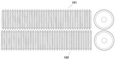
- Example 1 Five impregnated rolls were prepared (see FIG. 1). Grooved rolls were used for the first to fourth rolls (“13” in FIG. 1). Four rolls having a plurality of grooves with a width of 3 mm for the convex portion, a height of 10 mm and a width of 9 mm for the concave portion in the width direction of the roll were used. The second roll was installed so that the protrusions of the second roll were positioned between adjacent protrusions of the first roll when viewed from the vertical direction of the impregnation roll (see FIG. 2).
- the protrusions of the third roll were positioned between the protrusions of the second roll, and the protrusions of the fourth roll were positioned between the protrusions of the third roll.
- a smooth roll having no irregularities on the roll surface was used as the fifth roll ("8" in Fig. 1).
- the resin composition (1) obtained above was coated on a polyethylene-polypropylene laminate film (“12a” in FIG. 1) using a resin coating apparatus (“21a” in FIG. 1) at a coating amount of 0.00. 5 kg/m 2 , and carbon fiber roving (“T700SC-12000-50C” manufactured by Toray Industries, Inc.) (“23” in FIG. 1) is pulled out (“24” in FIG. 1).
- the carbon fiber (“24a” in FIG. 1) cut to 25 mm using the cutting device (“25” in FIG. 1) has no fiber orientation, the thickness is uniform, and the carbon fiber content is 50% by mass.
- resin composition (1) was applied onto a polyethylene-polypropylene laminate film (“12b” in FIG. 1) using a resin coating device (“21b” in FIG. 1). It was sandwiched between films coated so that the weight was 0.5 kg/m 2 .
- the sandwiched laminate (“9” in FIG. 1) was transported by a transfer belt (“20” in FIG. 1) and impregnated using the five impregnation rolls described above. After being impregnated with the resin composition (1), it was wound up and allowed to stand (aged) in a constant temperature machine at 45° C. for 24 hours to obtain a 1.8 mm thick carbon fiber reinforced composite material (X-1) (SMC) ( "7" in Fig. 1) was obtained. The basis weight of this carbon fiber reinforced composite material (X-1) was 2 kg/m 2 .
- Example 2 Of the five impregnation rolls used in Example 1, the fourth roll, which is a groove roll, was changed to a roll having a plurality of grooves with a protrusion width of 7 mm, a height of 10 mm, and a recess width of 5 mm.
- a carbon fiber reinforced composite material (X-2) (SMC) having a thickness of 1.8 mm was obtained in the same manner as in .
- the basis weight of this carbon fiber reinforced composite material (X-2) was 2 kg/m 2 .
- the obtained carbon fiber reinforced composite material (X-2) was molded in the same procedure as in Example 1 to obtain a flat molded product. No unevenness caused by the grooved roll was observed on the surface of the molded product.
- Example 1 Five impregnation rolls used in Example 1 were prepared. The second roll was installed so that the projections of the first roll and the projections of the second roll overlapped at the same positions when viewed from the vertical direction of the impregnation rolls. Similarly, the third roll was installed so that the protrusions of the third roll overlapped the positions of the protrusions of the second roll. The fourth roll was installed so that the position of the convex part of the 3rd roll also overlapped with the 4th roll. A smooth roll having no irregularities on the roll surface was used as the fifth roll.
- Example 2 Of the five impregnation rolls used in Example 1, the same procedure as in Example 1 was performed except that the positions of the convex portions of the first to fourth rolls, which are grooved rolls, were the same. A 1.8 mm carbon fiber reinforced composite (X-3) (SMC) was obtained. The basis weight of this carbon fiber reinforced composite material (X-3) was 2 kg/m 2 .
- the obtained carbon fiber reinforced composite material (X-3) was molded in the same procedure as in Example 1 to obtain a flat molded product. Unevenness caused by the grooved roll was observed on the surface of the molded product.
- Example 2 in the uneven grooves of the impregnation roll, the width of the protrusions is wider than the width of the recesses, so that the gap between the protrusions of the third roll and the protrusions of the fourth roll It was confirmed that the carbon fiber reinforced composite material can be made smooth by impregnating it with the convex portions of , and that the appearance is excellent without the occurrence of uneven patterns in the flat plate-shaped molded product.
- Comparative Example 1 since the convex portions of the adjacent impregnating rolls were arranged at the same positions, the pressure based on the convex portions of the impregnating rolls was increased, and even if a smooth roll was used as the final roll, the obtained flat plate was obtained. It was confirmed that the appearance of the molded product was poor, with the occurrence of uneven patterns in the molded product.
Landscapes
- Engineering & Computer Science (AREA)
- Mechanical Engineering (AREA)
- Reinforced Plastic Materials (AREA)
Abstract
本発明は、強化繊維に樹脂組成物を含浸させて繊維強化複合材料を製造する方法において、キャリアフィルム上に、前記強化繊維と前記樹脂組成物を積層して積層物を調製する工程と、前記積層物を、複数の含浸ロールを回転させながら押圧・進行することにより、前記強化繊維に、前記樹脂組成物を含浸する工程と、を含み、前記複数の含浸ロールの内、少なくとも、隣り合う2つの含浸ロールが、それぞれの表面に凹凸状の溝を有し、前記隣り合う2つの含浸ロールの一方の表面に有する凸部と凸部の間に、前記隣り合う2つの含浸ロールのもう一方の表面に有する凸部が配置され、前記複数の含浸ロールが、略同一平面上にあることを特徴とする繊維強化複合材料の製造方法に関する。
Description
本発明は、繊維強化複合材料の製造方法、前記製造方法により得られる繊維強化複合材料、及び、前記繊維強化複合材料を用いて得られる成形品の製造方法に関する。
近年、炭素繊維を強化繊維として、エポキシ樹脂や不飽和ポリエステル樹脂等の熱硬化性樹脂を強化した繊維強化複合材料は、軽量でありながら、耐熱性や機械強度に優れる特徴が注目され、住設部材、自動車部品、電気部品などに広く使用されている。
上記繊維強化複合材料に関して、エポキシ樹脂を使用した材料の成形方法としては、プリプレグと呼ばれる成形材料を加圧可能なオートクレーブで加熱し、硬化させるオートクレーブ法が知られており、不飽和ポリエステル樹脂を使用した材料の成形方法としては、シートモールディングコンパウンド(SMC)と呼ばれる中間材料を用いて、プレス成形、射出成形等の手法により、硬化、成形させる方法が知られている。特に近年では、生産性に優れる材料開発が活発に行われている。
また、上記SMCとしては、例えば、不飽和ポリエステル樹脂、無機充填剤、硬化剤、増粘剤、その他添加剤からなる液状の樹脂コンパウンド(樹脂組成物)をドクターナイフ方式などにより、キャリアフィルム上に一定の厚みで塗布した2組の樹脂コンパウンド層の間に、裁断したガラス繊維や炭素繊維等からなる強化繊維を挟み込み、強化繊維に樹脂コンパウンドを含浸させ、ロール状に巻き取り、その後、樹脂を増粘させることで(Bステージ化)、取り扱いに優れたシート状の成形材料(SMC)を繊維強化複合材料として得られるものである。なお、この樹脂コンパウンド(樹脂組成物)は、キャリアフィルム上に一定の厚みで塗布する際には液状で、強化繊維に含浸した後に、増粘後は、シート状の成形材料(SMC)を形成していることが求められる。
また、上記成形材料の中でも、炭素繊維を強化繊維として用いた炭素繊維強化複合材料は、自動車部品などに加えて、航空機等の筐体を軽量化する材料として、需要が高まっている。
また、炭素繊維を強化繊維として用いたSMCは、高強度で高弾性率の性能が求められる場合が多く、炭素繊維の含有量は、通常、SMC中、40質量%以上と高くする必要がある。炭素繊維は、比重が軽く、裁断した際に、その嵩密度が大きくなる。また、炭素繊維は、一般的に樹脂コンパウンドと親和性が低いため、嵩高い、高濃度の炭素繊維に樹脂コンパウンドを含浸させるためには、効率良く、樹脂コンパウンドの炭素繊維間に浸透させる必要がある。
上記強化繊維に樹脂コンパウンドを含浸させる方法として、例えば、剥離シート上に一定厚みで塗布して積層物とし、これを多数の針状の突起を有する回転ロールを用いて、押圧し、含浸させる方法などが挙げられる(特許文献1)。
ただ、上記強化繊維として、炭素繊維を使用する場合、前記炭素繊維は、引張弾性率が高いものの、しなやかで柔らかいため、繊維が屈曲した場合、元の直線状に戻りにくいため、メッシュベルトや凹凸ロールによって押圧された部分が、そのままの形状を維持した状態となり、SMC表面に凹凸が転写される場合がある。この状態でSMCを熟成(Bステージ化)すると、凹凸模様が残った状態のSMCが製造されてしまう。このSMCを成形すると、成形品表面にも凹凸模様が残り、外観不良となる恐れがあり、問題であった。
そこで、本発明が解決しようとする課題は、表面に凹凸状の溝を有する隣り合う含浸ロールのそれぞれの凸部の配置を制御することで、Bステージ化後のシート状の成形材料(繊維強化複合材料)や、前記繊維強化複合材料を用いて得られる成形品における含浸ロールに起因する凹凸模様の発生を回避できる、繊維強化複合材料の製造方法、前記繊維強化複合材料の製造方法により得られる繊維強化複合材料、及び、前記繊維強化複合材料を用いて得られる成形品の製造方法を提供することにある。
本発明者は、表面に凹凸状の溝を有する隣り合う含浸ロールのそれぞれの凸部の配置を制御することで、Bステージ化後のシート状の成形材料(繊維強化複合材料)や、前記繊維強化複合材料を用いて得られる成形品における含浸ロールに起因する凹凸模様の発生を回避できる繊維強化複合材料の製造方法を見出し、本発明を完成した。
すなわち、本発明は、強化繊維に樹脂組成物を含浸させて繊維強化複合材料を製造する方法において、キャリアフィルム上に、前記強化繊維と前記樹脂組成物を積層して積層物を調製する工程と、前記積層物を、複数の含浸ロールを回転させながら押圧・進行することにより、前記強化繊維に、前記樹脂組成物を含浸する工程と、を含み、前記複数の含浸ロールの内、少なくとも、隣り合う2つの含浸ロールが、それぞれの表面に凹凸状の溝を有し、前記隣り合う2つの含浸ロールの一方の表面に有する凸部と凸部の間に、前記隣り合う2つの含浸ロールのもう一方の表面に有する凸部が配置され、前記複数の含浸ロールが、略同一平面上にあることを特徴とする繊維強化複合材料の製造方法に関する。
本発明の繊維強化複合材料の製造方法は、前記強化繊維に、前記樹脂組成物を含浸した後、加熱する工程、を含むことが好ましい。
本発明の繊維強化複合材料の製造方法は、前記複数の含浸ロールの内、前記進行する方向に対して、最終ロールが、平滑のロールであることが好ましい。
本発明の繊維強化複合材料の製造方法は、前記凹凸状の溝の内、凸部の幅が、凹部の幅よりも広いものを用いることができる。
本発明の繊維強化複合材料の製造方法は、前記凹凸状の溝の内、凸部の幅が、凹部の幅よりも狭いものを用いることができる。
本発明の繊維強化複合材料の製造方法は、前記進行する方向に対して、前記凸部の幅が広くなることが好ましい。
本発明は、前記繊維強化複合材料の製造方法により得られることを特徴とする繊維強化複合材料に関する。
本発明は、前記繊維強化複合材料を用いて得られることを特徴とする成形品の製造方法に関する。
本発明の繊維強化複合材料の製造方法は、表面に凹凸状の溝を有する隣り合う含浸ロールのそれぞれの凸部の配置を制御することで、Bステージ化後のシート状の成形材料(繊維強化複合材料)や、前記繊維強化複合材料を用いて得られる成形品における含浸ロールに起因する凹凸模様の発生を回避でき、前記製造方法を用いて得られる繊維強化複合材料は、外観性に優れ、有用である。
以下、本発明の実施形態について詳細に説明する。
[樹脂組成物]
本発明の繊維強化複合材料の製造方法に用いる樹脂組成物としては、特に制限されないが、熱硬化性樹脂等の用途に使用される樹脂等を使用することが好ましく、例えば、ビニルエステル樹脂、不飽和単量体、ポリイソシアネート、及び、重合開始剤などを原料成分として使用することができる。
本発明の繊維強化複合材料の製造方法に用いる樹脂組成物としては、特に制限されないが、熱硬化性樹脂等の用途に使用される樹脂等を使用することが好ましく、例えば、ビニルエステル樹脂、不飽和単量体、ポリイソシアネート、及び、重合開始剤などを原料成分として使用することができる。
[ビニルエステル樹脂]
前記ビニルエステル樹脂としては、エポキシ樹脂と不飽和単量体(例えば、(メタ)アクリル酸)とを反応させることにより得られるが、成形時のフィルム剥離性やタック性等の取扱性と流動性とのバランスに優れることから、前記エポキシ樹脂のエポキシ基(EP)と前記(メタ)アクリル酸のカルボキシル基(COOH)とのモル比(COOH/EP)を0.6~1.1の範囲で反応させることが好ましい。
前記ビニルエステル樹脂としては、エポキシ樹脂と不飽和単量体(例えば、(メタ)アクリル酸)とを反応させることにより得られるが、成形時のフィルム剥離性やタック性等の取扱性と流動性とのバランスに優れることから、前記エポキシ樹脂のエポキシ基(EP)と前記(メタ)アクリル酸のカルボキシル基(COOH)とのモル比(COOH/EP)を0.6~1.1の範囲で反応させることが好ましい。
また、上記バランスの観点から、前記エポキシ樹脂のエポキシ当量は、170~360g/eqの範囲が好ましく、180~280g/eqの範囲がより好ましい。
なお、本発明において、「(メタ)アクリル酸」とは、アクリル酸とメタクリル酸の一方又は両方をいい、「(メタ)アクリレート」とは、アクリレートとメタクリレートの一方又は両方をいう。
前記エポキシ樹脂としては、例えば、ビスフェノールA型エポキシ樹脂、ビスフェノールF型エポキシ樹脂、ビスフェノールフルオレン型エポキシ樹脂、ビスクレゾールフルオレン型等のビスフェノール型エポキシ樹脂、フェノールノボラック型エポキシ樹脂、クレゾールノボラック型エポキシ樹脂等のノボラック型エポキシ樹脂、オキゾドリドン変性エポキシ樹脂、これらの樹脂の臭素化エポキシ樹脂等のフェノールのグリシジルエーテル、ジプロピレングリコールジグリシジルエーテル、トリメチロールプロパントリグリシジルエーテル、ビスフェノールAのアルキレンオキサイド付加物のジグリシジルエーテル、水素化ビスフェノールAのジグリシジルエーテル等の多価アルコールのグリシジルエーテル、3,4-エポキシ-6-メチルシクロヘキシルメチル-3,4-エポキシ-6-メチルシクロヘキサンカルボキシレート、1-エポシエチル-3,4-エポキシシクロヘキサン等の脂環式エポキシ樹脂、フタル酸ジグリシジルエステル、テトラヒドロフタル酸ジグリシジルエステル、ジグリシジル-p-オキシ安息香酸、ダイマー酸グリシジルエステルなどのグリシジルエステル、テトラグリシジルジアミノジフェニルメタン、テトラグリシジル-m-キシレンジアミン、トリグリシジル-p一アミノフェノール、N,N-ジグリシジルアニリンなどのグリシジルアミン、1,3-ジグリシジル-5,5-ジメチルヒダントイン、トリグリシジルイソシアヌレートなどの複素環式エポキシ樹脂などが挙げられる。これらの中でも、成形品強度と成形材料の取り扱い性、成形材料の成形時の流動性により優れることから2官能性芳香族系エポキシ樹脂が好ましく、ビスフェノールA型エポキシ樹脂およびビスフェノールF型エポキシ樹脂がより好ましい。なお、これらのエポキシ樹脂は、単独で用いることも2種以上併用することもできる。
また、前記エポキシ樹脂としては、エポキシ当量を調整するために、ビスフェノールA等の二塩基酸により、高分子量化し、使用してもよい。
前記エポキシ樹脂と(メタ)アクリル酸との反応は、エステル化触媒を用い、60~140℃において行われることが好ましい。また、重合禁止剤等を使用することもできる。なお、前記エポキシ樹脂と(メタ)アクリル酸との反応により、ビニルエステル樹脂を得ることができる。
[不飽和単量体]
前記不飽和単量体としては、例えば、ベンジル(メタ)アクリレート、フェノキシエチル(メタ)アクリレート、フェノキシポリエチレングリコール(メタ)アクリレート、ポリエチレングリコール(メタ)アクリレートアルキルエーテル、ポリプロピレングリコール(メタ)アクリレートアルキルエーテル、2-エチルヘキシルメタクリレート、イソデシル(メタ)アクリレート、ラウリル(メタ)アクリレート、イソトリデシル(メタ)アクリレート、n-ステアリル(メタ)アクリレート、テトラヒドロフルフリルメタクリレート、イソボルニル(メタ)アクリレート、ジシクロペンテニルオキシエチル(メタ)アクリレート、ジシクロペンタニルメタクリレート等の単官能(メタ)アクリレート化合物;エチレングリコールジ(メタ)アクリレート、プロピレングリコールジ(メタ)アクリレート、1,4-ブタンジオールジ(メタ)アクリレート、1,3-ブタンジオールジ(メタ)アクリレート、ネオペンチルグリコールジ(メタ)アクリレート、1,6-ヘキサンジオールジ(メタ)アクリレート、ビスフェノールジ(メタ)アクリレート、1,4-シクロヘキサンジメタノールジ(メタ)アクリレート等のジ(メタ)アクリレート化合物;ジアリルフタレート、ジビニルベンゼン、スチレンなどが挙げられるが、これらの中でも、より高強度の成形材料が得られることから、芳香族を有する不飽和単量体が好ましく、ベンジルメタクリレート、フェノキシエチルメタクリレートがより好ましい。なお、これらの不飽和単量体は単独で用いることも2種以上併用することもできる。
前記不飽和単量体としては、例えば、ベンジル(メタ)アクリレート、フェノキシエチル(メタ)アクリレート、フェノキシポリエチレングリコール(メタ)アクリレート、ポリエチレングリコール(メタ)アクリレートアルキルエーテル、ポリプロピレングリコール(メタ)アクリレートアルキルエーテル、2-エチルヘキシルメタクリレート、イソデシル(メタ)アクリレート、ラウリル(メタ)アクリレート、イソトリデシル(メタ)アクリレート、n-ステアリル(メタ)アクリレート、テトラヒドロフルフリルメタクリレート、イソボルニル(メタ)アクリレート、ジシクロペンテニルオキシエチル(メタ)アクリレート、ジシクロペンタニルメタクリレート等の単官能(メタ)アクリレート化合物;エチレングリコールジ(メタ)アクリレート、プロピレングリコールジ(メタ)アクリレート、1,4-ブタンジオールジ(メタ)アクリレート、1,3-ブタンジオールジ(メタ)アクリレート、ネオペンチルグリコールジ(メタ)アクリレート、1,6-ヘキサンジオールジ(メタ)アクリレート、ビスフェノールジ(メタ)アクリレート、1,4-シクロヘキサンジメタノールジ(メタ)アクリレート等のジ(メタ)アクリレート化合物;ジアリルフタレート、ジビニルベンゼン、スチレンなどが挙げられるが、これらの中でも、より高強度の成形材料が得られることから、芳香族を有する不飽和単量体が好ましく、ベンジルメタクリレート、フェノキシエチルメタクリレートがより好ましい。なお、これらの不飽和単量体は単独で用いることも2種以上併用することもできる。
前記ビニルエステル樹脂と前記不飽和単量体との質量比(ビニルエステル樹脂/不飽和単量体)は、強化繊維への樹脂含浸性、取り扱い性と硬化性のバランスがより向上することから、40/60~85/15の範囲が好ましく、50/50~70/30の範囲がより好ましい。
[ポリイソシアネート]
前記ポリイソシアネートとしては、例えば、ジフェニルメタンジイソシアネート(4,4’-体、2,4’-体、又は2,2’-体、もしくはそれらの混合物)、ジフェニルメタンジイソシアネートのカルボジイミド変性体、ヌレート変性体、ビュレット変性体、ウレタンイミン変性体、ジエチレングリコールやジプロピレングリコール等の数平均分子量1,000以下のポリオールで変性したポリオール変性体等のジフェニルメタンジイソシアネート変性体、トリレンジイソシアネート、トリジンジイソシアネート、ポリメチレンポリフェニルポリイソシアネート、キシリレンジイソシアネート、1,5-ナフタレンジイソシアネート、テトラメチルキシレンジイソシアネート等の芳香族ポリイソシアネート;イソホロンジイソシアネート、水添ジフェニルメタンジイソシアネート、水添キシリレンジイソシアネート、ノルボルネンジイソシアネート等の脂環式ポリイソシアネート;ヘキサメチレンジイソシアネート、ヘキサメチレンジイソシアネートのヌレート変性体、ビュレット変性体、アダクト体、ダイマー酸ジイソシアネート等の脂肪族ポリイソシアネートなどを用いることができる。これらの中でも、取り扱い性(フィルム剥離性・タック性)に優れる成形材料が得られることから、芳香族ポリイソシアネートが好ましい。なお、これらのポリイソシアネートは、単独で用いることも2種以上併用することもできる。
前記ポリイソシアネートとしては、例えば、ジフェニルメタンジイソシアネート(4,4’-体、2,4’-体、又は2,2’-体、もしくはそれらの混合物)、ジフェニルメタンジイソシアネートのカルボジイミド変性体、ヌレート変性体、ビュレット変性体、ウレタンイミン変性体、ジエチレングリコールやジプロピレングリコール等の数平均分子量1,000以下のポリオールで変性したポリオール変性体等のジフェニルメタンジイソシアネート変性体、トリレンジイソシアネート、トリジンジイソシアネート、ポリメチレンポリフェニルポリイソシアネート、キシリレンジイソシアネート、1,5-ナフタレンジイソシアネート、テトラメチルキシレンジイソシアネート等の芳香族ポリイソシアネート;イソホロンジイソシアネート、水添ジフェニルメタンジイソシアネート、水添キシリレンジイソシアネート、ノルボルネンジイソシアネート等の脂環式ポリイソシアネート;ヘキサメチレンジイソシアネート、ヘキサメチレンジイソシアネートのヌレート変性体、ビュレット変性体、アダクト体、ダイマー酸ジイソシアネート等の脂肪族ポリイソシアネートなどを用いることができる。これらの中でも、取り扱い性(フィルム剥離性・タック性)に優れる成形材料が得られることから、芳香族ポリイソシアネートが好ましい。なお、これらのポリイソシアネートは、単独で用いることも2種以上併用することもできる。
前記ポリイソシアネートのイソシアネート基(NCO)と前記ビニルエステル樹脂の水酸基(OH)とのモル比(NCO/OH)は、溶融粘度を容易に制御できることから、0.5~0.95の範囲が好ましく、0.55~0.85がより好ましい。
[重合開始剤]
前記重合開始剤としては、特に限定されないが、有機過酸化物が好ましく、例えば、ジアシルパーオキサイド化合物、パーオキシエステル化合物、ハイドロパーオキサイド化合物、ケトンパーオキサイド化合物、アルキルパーエステル化合物、パーカーボネート化合物、パーオキシケタール等が挙げられ、成形条件に応じて適宜選択できる。なお、これらの重合開始剤は、単独で用いることも2種以上併用することもできる。
前記重合開始剤としては、特に限定されないが、有機過酸化物が好ましく、例えば、ジアシルパーオキサイド化合物、パーオキシエステル化合物、ハイドロパーオキサイド化合物、ケトンパーオキサイド化合物、アルキルパーエステル化合物、パーカーボネート化合物、パーオキシケタール等が挙げられ、成形条件に応じて適宜選択できる。なお、これらの重合開始剤は、単独で用いることも2種以上併用することもできる。
また、前記有機過酸化物の中でも、成形時間を短縮する目的で、10時間半減期を得るための温度が70~110℃の重合開始剤を使用するのが好ましい。前記温度の範囲内であれば、繊維強化複合材料の常温でのライフが長く、また、加熱により短時間で硬化ができるため好ましく、硬化性と成形性のバランスがより優れる。このような重合開始剤としては、例えば、1,6-ビス(t-ブチルパーオキシカルボニロキシ)ヘキサン、1,1-ビス(t-ブチルパーオキシ)シクロヘキサン、1,1-ビス(t-アミルパーオキシ)シクロヘキサン、1,1-ビス(t-ヘキシルパーオキシ)シクロヘキサン、t-ブチルパーオキシジエチルアセテート、t-ブチルパーオキシイソプロピルカーボネート、t-アミルパーオキシイソプロピルカーボネート、t-ヘキシルパーオキシイソプロピルカーボネート、ジーtert-ブチルパーオキシヘキサハイドロテレフタレート、t-アミルパーオキシトリメチルヘキサノエート等が挙げられる。
前記重合開始剤の含有量としては、硬化特性と保存安定性が共に優れることから、前記ビニルエステル樹脂と前記不飽和単量体との総量に対して、0.3~3質量%の範囲が好ましい。
前記樹脂組成物としては、前記ビニルエステル樹脂、前記不飽和単量体、前記ポリイソシアネート、及び、前記重合開始剤以外のものを使用してもよく、例えば、前記ビニルエステル樹脂以外の熱硬化性樹脂、熱可塑性樹脂、重合禁止剤、硬化促進剤、充填剤、低収縮剤、離型剤、増粘剤、減粘剤、顔料、酸化防止剤、可塑剤、難燃剤、抗菌剤、紫外線安定剤、補強材、光硬化剤等を含有することができる。
前記熱硬化性樹脂としては、例えば、ビニルウレタン樹脂、不飽和ポリエステル樹脂、アクリル樹脂、エポキシ樹脂、フェノール樹脂、メラミン樹脂、フラン樹脂等が挙げられる。また、これらの熱硬化性樹脂は、単独で用いることも2種以上併用することもできる。
前記熱可塑性樹脂としては、例えば、ポリアミド樹脂、ポリエチレンテレフタレート樹脂、ポリブチレンテレフタレート樹脂、ポリカーボネート樹脂、ウレタン樹脂、ポリプロピレン樹脂、ポリエチレン樹脂、ポリスチレン樹脂、アクリル樹脂、ポリブタジエン樹脂、ポリイソプレン樹脂およびこれらを共重合等により変性させたものが挙げられる。また、これらの熱可塑性樹脂は、単独で用いることも2種以上併用することもできる。
前記重合禁止剤としては、例えば、ハイドロキノン、トリメチルハイドロキノン、p-t-ブチルカテコール、t-ブチルハイドロキノン、トルハイドロキノン、p-ベンゾキノン、ナフトキノン、ハイドロキノンモノメチルエーテル、フェノチアジン、ナフテン酸銅、塩化銅等が挙げられる。これらの重合禁止剤は、単独で用いることも2種以上を併用することもできる。
前記硬化促進剤としては、例えば、ナフテン酸コバルト、オクテン酸コバルト、オクテン酸バナジル、ナフテン酸銅、ナフテン酸バリウム等の金属石鹸類、バナジルアセチルアセテート、コバルトアセチルアセテート、鉄アセチルアセトネート等の金属キレート化合物が挙げられる。またアミン類として、N,N-ジメチルアミノ-p-ベンズアルデヒド、N,N-ジメチルアニリン、N,N-ジエチルアニリン、N,N-ジメチル-p-トルイジン、N-エチル-m-トルイジン、トリエタノールアミン、m-トルイジン、ジエチレントリアミン、ピリジン、フェニルモルホリン、ピペリジン、ジエタノールアニリン等が挙げられる。これらの硬化促進剤は、単独で用いることも2種以上を併用することもできる。
前記充填剤としては、無機化合物、有機化合物があり、成形品強度、弾性率、衝撃強度、疲労耐久性等の物性を調整するために使用できる。
前記無機化合物としては、例えば、炭酸カルシウム、炭酸マグネシウム、硫酸バリウム、マイカ、タルク、カオリン、クレー、セライト、アスベスト、バーライト、バライタ、シリカ、ケイ砂、ドロマイト石灰石、石こう、アルミニウム微粉、中空バルーン、アルミナ、ガラス粉、水酸化アルミニウム、寒水石、酸化ジルコニウム、三酸化アンチモン、酸化チタン、二酸化モリブデン、鉄粉等が挙げられる。
前記有機化合物としては、セルロース、キチン等の天然多糖類粉末や、合成樹脂粉末等があり、合成樹脂粉末としては、硬質樹脂、軟質ゴム、エラストマーまたは重合体(共重合体)などから構成される有機物の粉体やコアシェル型などの多層構造を有する粒子を使用できる。具体的には、ブタジエンゴムおよび/またはアクリルゴム、ウレタンゴム、シリコンゴム等からなる粒子、ポリイミド樹脂粉末、フッ素樹脂粉末、フェノール樹脂粉末などが挙げられる。これらの充填剤は、単独で用いることも2種以上を併用することもできる。
前記有機化合物としては、セルロース、キチン等の天然多糖類粉末や、合成樹脂粉末等があり、合成樹脂粉末としては、硬質樹脂、軟質ゴム、エラストマーまたは重合体(共重合体)などから構成される有機物の粉体やコアシェル型などの多層構造を有する粒子を使用できる。具体的には、ブタジエンゴムおよび/またはアクリルゴム、ウレタンゴム、シリコンゴム等からなる粒子、ポリイミド樹脂粉末、フッ素樹脂粉末、フェノール樹脂粉末などが挙げられる。これらの充填剤は、単独で用いることも2種以上を併用することもできる。
前記離型剤としては、例えば、ステアリン酸亜鉛、ステアリン酸カルシウム、パラフィンワックス、ポリエチレンワックス、カルナバワックスなどが挙げられる。好ましくは、パラフィンワックス、ポリエチレンワックス、カルナバワックス等が挙げられる。これらの離型剤は、単独で用いることも、2種以上を併用することもできる。
前記増粘剤としては、例えば、酸化マグネシウム、水酸化マグネシウム、酸化カルシウム、水酸化カルシウム等の金属酸化物や金属水酸化物など、アクリル樹脂系微粒子などが挙げられる。これらの増粘剤は、単独で用いることも、2種以上を併用することもできる。
また、前記樹脂組成物の粘度は、強化繊維への樹脂含浸性が向上することから、200~8000mPa・s(25℃)の範囲が好ましい。
[強化繊維]
前記強化繊維としては、特に制限されないが、機械的強度や耐久性の観点から、炭素繊維が好ましく、高強度の炭素繊維が得られることから、ポリアクリロニトリル系、ピッチ系、レーヨン系などの各種のものが使用でき、中でも、容易に高強度の炭素繊維が得られることから、ポリアクリロニトリル系のものがより好ましい。
前記強化繊維としては、特に制限されないが、機械的強度や耐久性の観点から、炭素繊維が好ましく、高強度の炭素繊維が得られることから、ポリアクリロニトリル系、ピッチ系、レーヨン系などの各種のものが使用でき、中でも、容易に高強度の炭素繊維が得られることから、ポリアクリロニトリル系のものがより好ましい。
前記炭素繊維としては、2.5~50mmの長さにカットした炭素繊維が用いられるが、成形時の金型内流動性、成形品の外観及び機械的物性がより向上することから、5~40mmにカットした炭素繊維がより好ましい。
前記炭素繊維として使用される繊維束のフィラメント数は、樹脂含浸性及び成形品の機械的物性がより向上することから、1000~60000が好ましい。
本発明の繊維強化複合材料の製造方法により得られる繊維強化複合材料の成分中の、前記強化繊維の含有率は、得られる繊維強化複合材料から得られる成形品の機械的強度がより向上することから、20~80質量%の範囲が好ましく、40~70質量%の範囲がより好ましい。前記強化繊維の含有率が低いと、高強度な成形品が得られない可能性があり、前記強化繊維の含有率が高いと、繊維への樹脂含浸性が不十分で、成形品に膨れが生じ、やはり高強度な成形品が得られない可能性がある。
[繊維強化複合材料の製造方法]
本発明は、強化繊維に樹脂組成物を含浸させて繊維強化複合材料を製造する方法において、キャリアフィルム上に、前記強化繊維と前記樹脂組成物を積層して積層物を調製する工程と、前記積層物を、複数の含浸ロールを回転させながら押圧・進行することにより、前記強化繊維に、前記樹脂組成物を含浸する工程と、を含み、前記複数の含浸ロールの内、少なくとも、隣り合う2つの含浸ロールが、それぞれの表面に凹凸状の溝を有し、前記隣り合う2つの含浸ロールの一方の表面に有する凸部と凸部の間に、前記隣り合う2つの含浸ロールのもう一方の表面に有する凸部が配置され、前記複数の含浸ロールが、略同一平面上にあることを特徴とする繊維強化複合材料の製造方法に関する。
本発明の繊維強化複合材料の製造方法においては、前記含浸ロールの内、少なくとも、隣り合う2つの含浸ロールが、それぞれの表面に凹凸状の溝を有し、前記隣り合う2つの含浸ロールの一方の表面に有する凸部と凸部の間に、前記隣り合う2つの含浸ロールのもう一方の表面に有する凸部が配置されることで、含浸ロールと接触する積層物表面への圧力が分散され、含浸ロールに起因する凹凸模様の発生を抑制でき、好ましい。一方、従前のように、隣り合う含浸ロールの凸部が、それぞれ、同じ位置に配置される場合、含浸ロールと接触する積層物表面への圧力が同じ位置に掛かることになり、含浸ロールに起因する凹凸模様が発生する原因となるため、好ましくない。
なお、前記隣り合う2つの含浸ロールの一方の表面に有する凸部と凸部の間に、前記隣り合う2つの含浸ロールのもう一方の表面に有する凸部が配置されるが、前記隣り合う凸部同士の一部が重なりあってもいてもよい。前記重なり合っていることで、前記凸部と接触する前記積層物の表面が、平面状に均されることになり、含浸ロールに起因する凹凸模様の発生を抑制しやすくなり、好ましい。
また、本発明の繊維強化複合材料の製造方法においては、前記複数の含浸ロールが、略同一平面上にあることで、含浸ロールと接触する積層物表面への圧力が分散され、含浸ロールに起因する凹凸模様の発生を抑制でき、好ましい。一方、従前のように、複数の含浸ロールが存在する場合に、略同一平面上になく、隣り合う含浸ロールに上下差があるような場合(例えば、つづら折り状に配置)、積層物表面への圧力が均一に掛からない場合があり、これを解消するため、含浸ロールの形状を様々変更する必要などがあり、作業性が劣り、含浸ロールを含む装置の価格上昇などが生じることもあり、好ましくない。ここで、「略」同一平面とは、含浸ロールの凸部を含む直径に対して±10%以内の上下差の違いを意味する。
なお、前記複数の含浸ロールとして、少なくとも、隣り合う2つの含浸ロールが、それぞれの表面に凹凸状の溝を有し、前記隣り合う2つの含浸ロールの一方の表面に有する凸部と凸部の間に、前記隣り合う2つの含浸ロールのもう一方の表面に有する凸部が配置されるが、それ以外に、例えば、複数(n個)の含浸ロールの全ての表面に凹凸状の溝を有し、全ての含浸ロールにおいて、垂直方向から見て、第一ロールの表面に有する凸部と凸部の間に、第二ロールの凸部が配置され、同様に第二ロールの表面に有する凸部と凸部の間に、第三ロールの凸部が配置されるように配置するといったものなどであってもよいし、更に、第四ロール及び第五ロールは、上記条件を満たさず、その後、第六ロール及び第七ロールが上記条件を満たすなどの組合せであっても、含浸ロールに起因する凹凸模様が発生を抑制できる場合であれば、特に問題はない。
前記隣り合う2つの含浸ロールの凹凸状の溝は、全て同じ形状であって良いし、異なっていても良い。前記凹凸状の溝の形状が異なる場合は、隣り合う2つの含浸ロールの一方の表面に有する凸部と凸部の配置のピッチと、もう一方の表面に有する凸部の配置のピッチが同じであることが好ましい。
更に、本発明の繊維強化複合材料の製造方法は、前記強化繊維に、前記樹脂組成物を含浸した後、加熱(熟成)する工程、を含むことが好ましい。
本発明の繊維強化複合材料の製造方法においては、上記製造工程と共に、前記強化繊維に、前記樹脂組成物を含浸した後の加熱(熟成)工程を経ることで、Bステージ化後のシート状の成形材料(SMC)としての繊維強化複合材料が得られ、作業性や、フィルムの剥離性等に優れ、好ましい。
本発明の繊維強化複合材料の製造方法においては、上記製造工程と共に、前記強化繊維に、前記樹脂組成物を含浸した後の加熱(熟成)工程を経ることで、Bステージ化後のシート状の成形材料(SMC)としての繊維強化複合材料が得られ、作業性や、フィルムの剥離性等に優れ、好ましい。
本発明の繊維強化複合材料の製造方法は、前記複数の含浸ロールの内、前記進行する方向に対して、最終ロールが、平滑のロールであることが好ましい。
前記複数の含浸ロールの内、前記積層物を、複数の含浸ロールを回転させながら押圧・進行させる際の進行方向の最終ロールが、平滑のロールであることで、たとえ、シート状の成形材料(SMC)が、最終ロールに到達する前に、多少の凹凸が発生した場合であっても、前記平滑ロールにより、凹凸による撓み(歪み)を抑えることができ、好ましい。
なお、前記平滑ロールとしては、最終ロールであることが好ましいが、最終ロール以外の含浸ロールにおいて、平滑ロールを含んでいてもよいし、最終ロールでない場合であっても、複数の含浸ロールの後半に配置された含浸ロールが平滑であってもよい。
前記複数の含浸ロールの内、前記積層物を、複数の含浸ロールを回転させながら押圧・進行させる際の進行方向の最終ロールが、平滑のロールであることで、たとえ、シート状の成形材料(SMC)が、最終ロールに到達する前に、多少の凹凸が発生した場合であっても、前記平滑ロールにより、凹凸による撓み(歪み)を抑えることができ、好ましい。
なお、前記平滑ロールとしては、最終ロールであることが好ましいが、最終ロール以外の含浸ロールにおいて、平滑ロールを含んでいてもよいし、最終ロールでない場合であっても、複数の含浸ロールの後半に配置された含浸ロールが平滑であってもよい。
本発明の繊維強化複合材料の製造方法は、前記凹凸状の溝の内、凸部の幅が、凹部の幅よりも広いものを用いることができ、また、前記凹凸状の溝の内、凸部の幅が、凹部の幅よりも狭いものであっても、用いることができる。
前記複数の含浸ロールの内、少なくとも、隣り合う2つの含浸ロールが、それぞれの表面に凹凸状の溝を有し、前記隣り合う2つの含浸ロールの一方の表面に有する凸部と凸部の間に、前記隣り合う2つの含浸ロールのもう一方の表面に有する凸部が配置され、前記凹凸状の溝の内、凸部の幅が、凹部の幅よりも広いものであっても、狭いものであっても、含浸ロールと接触する積層物表面への圧力が分散され、含浸ロールに起因する凹凸模様の発生を抑制でき、好ましいが、特に、前記凹凸状の溝の内、凸部の幅が、凹部の幅よりも広いものを使用することで、含浸ロールと積層物の接触面積が大きくなり、より圧力が分散され、凹凸模様の発生を抑制でき、好ましい。
前記複数の含浸ロールの内、少なくとも、隣り合う2つの含浸ロールが、それぞれの表面に凹凸状の溝を有し、前記隣り合う2つの含浸ロールの一方の表面に有する凸部と凸部の間に、前記隣り合う2つの含浸ロールのもう一方の表面に有する凸部が配置され、前記凹凸状の溝の内、凸部の幅が、凹部の幅よりも広いものであっても、狭いものであっても、含浸ロールと接触する積層物表面への圧力が分散され、含浸ロールに起因する凹凸模様の発生を抑制でき、好ましいが、特に、前記凹凸状の溝の内、凸部の幅が、凹部の幅よりも広いものを使用することで、含浸ロールと積層物の接触面積が大きくなり、より圧力が分散され、凹凸模様の発生を抑制でき、好ましい。
本発明の繊維強化複合材料の製造方法は、前記進行する方向に対して、前記凸部の幅が広くなることが好ましい。
前記複数の含浸ロールの内、少なくとも、隣り合う2つの含浸ロールが、それぞれの表面に凹凸状の溝を有し、前記隣り合う2つの含浸ロールの一方の表面に有する凸部と凸部の間に、前記隣り合う2つの含浸ロールのもう一方の表面に有する凸部が配置され、前記進行する方向に対して、前記凸部の幅が広くなることで、含浸ロールと接触する積層物表面への圧力が分散され、含浸ロールに起因する凹凸模様の発生を抑制でき、好ましい。一方、凸部の幅が、進行方向に対して、狭くなる場合、含浸ロールと接触する積層物表面への圧力が高くなり、含浸ロールに起因する凹凸模様の発生を誘発することになり、好ましくない。
前記複数の含浸ロールの内、少なくとも、隣り合う2つの含浸ロールが、それぞれの表面に凹凸状の溝を有し、前記隣り合う2つの含浸ロールの一方の表面に有する凸部と凸部の間に、前記隣り合う2つの含浸ロールのもう一方の表面に有する凸部が配置され、前記進行する方向に対して、前記凸部の幅が広くなることで、含浸ロールと接触する積層物表面への圧力が分散され、含浸ロールに起因する凹凸模様の発生を抑制でき、好ましい。一方、凸部の幅が、進行方向に対して、狭くなる場合、含浸ロールと接触する積層物表面への圧力が高くなり、含浸ロールに起因する凹凸模様の発生を誘発することになり、好ましくない。
[含浸ロール]
前記含浸ロールとしては、特に限定されないが、材質としては金属、ゴム、プラスチックなどが挙げられる。含浸ロール表面に設けられる凹凸状の模様としては、特に制限されないが、ロールの周方向に凹凸が設けられた溝状、ロール表面に棒状、針状、千鳥状に設けられていても良い。これらの中でも、隣り合う含浸ロールの表面の凸部の位置制御を容易するため、溝ロールが好ましい。前記溝ロールの凸部は、幅方向に丸みを帯びていてもよく、丸みを帯びていなくても良い。また、前記溝ロールの凸部は深さ方向に幅が一定であっても良く、幅が広くなっていても良い。
前記含浸ロールとしては、特に限定されないが、材質としては金属、ゴム、プラスチックなどが挙げられる。含浸ロール表面に設けられる凹凸状の模様としては、特に制限されないが、ロールの周方向に凹凸が設けられた溝状、ロール表面に棒状、針状、千鳥状に設けられていても良い。これらの中でも、隣り合う含浸ロールの表面の凸部の位置制御を容易するため、溝ロールが好ましい。前記溝ロールの凸部は、幅方向に丸みを帯びていてもよく、丸みを帯びていなくても良い。また、前記溝ロールの凸部は深さ方向に幅が一定であっても良く、幅が広くなっていても良い。
[シートモールディングコンパウンド(SMC)]
前記SMCの製造方法としては、通常のミキサー、インターミキサー、プラネタリーミキサー、ロール、ニーダー、押し出し機などの混合機を用いて、前記樹脂組成物に含まれる各成分を混合・分散し、得られた樹脂組成物を上下に設置されたキャリアフィルムに均一な厚さになるように塗布し、前記強化繊維を前記上下に設置されたキャリアフィルム上の樹脂組成物で挟み込み、次いで、全体を含浸ロールの間に通して、圧力を加えて、前記強化繊維に樹脂組成物を含浸させた後、ロール状に巻き取る等の方法が挙げられる。さらに、この後、20~60℃の温度領域で、12~72時間加熱(熟成)を行い、SMCとすることができ、また、複数の温度領域により、加熱(熟成)してもよい。なお、加熱(熟成)とは、低温(例えば、20℃程度)から高温(例えば、60℃程度)領域を指し、目的に応じて、調整することができる。SMCの厚みは所望の性能や用途に応じて適宜設定できるが、成形性や硬化物における強度等に優れることから、1mm以上であることが好ましく、1.2mm以上であることがより好ましく、1.5mm以上であることが特に好ましい。また、10mm以下であることが好ましく、5mm以下であることがより好ましく、4mm以下であることが特に好ましい。
前記SMCの製造方法としては、通常のミキサー、インターミキサー、プラネタリーミキサー、ロール、ニーダー、押し出し機などの混合機を用いて、前記樹脂組成物に含まれる各成分を混合・分散し、得られた樹脂組成物を上下に設置されたキャリアフィルムに均一な厚さになるように塗布し、前記強化繊維を前記上下に設置されたキャリアフィルム上の樹脂組成物で挟み込み、次いで、全体を含浸ロールの間に通して、圧力を加えて、前記強化繊維に樹脂組成物を含浸させた後、ロール状に巻き取る等の方法が挙げられる。さらに、この後、20~60℃の温度領域で、12~72時間加熱(熟成)を行い、SMCとすることができ、また、複数の温度領域により、加熱(熟成)してもよい。なお、加熱(熟成)とは、低温(例えば、20℃程度)から高温(例えば、60℃程度)領域を指し、目的に応じて、調整することができる。SMCの厚みは所望の性能や用途に応じて適宜設定できるが、成形性や硬化物における強度等に優れることから、1mm以上であることが好ましく、1.2mm以上であることがより好ましく、1.5mm以上であることが特に好ましい。また、10mm以下であることが好ましく、5mm以下であることがより好ましく、4mm以下であることが特に好ましい。
前記キャリアフィルムとしては、ポリエチレンフィルム、ポリプロピレンフィルム、ポリエチレンとポリプロピレンのラミネートフィルム、ポリエチレンテレフタレート、ナイロン等を用いることができる。
[成形品の製造方法]
本発明は、前記繊維強化複合材料を用いて得られることを特徴とする成形品の製造方法に関する。前記繊維強化複合材料を用いて得られる成形品の製造方法により得られる成形品は、生産性や外観性に優れる観点から、その成形方法としては、SMCの加熱圧縮成形が好ましい。
本発明は、前記繊維強化複合材料を用いて得られることを特徴とする成形品の製造方法に関する。前記繊維強化複合材料を用いて得られる成形品の製造方法により得られる成形品は、生産性や外観性に優れる観点から、その成形方法としては、SMCの加熱圧縮成形が好ましい。
前記加熱圧縮成形としては、例えば、SMC等の成形材料を所定量計量し、予め、110~180℃に加熱した金型に投入し、圧縮成形機にて型締めを行い、成形材料を賦型させ、0.1~30MPaの成形圧力を保持することによって、成形材料を硬化させ、その後、得られた成形品を取り出すことで、成形品を製造することができる。
[用途]
本発明の繊維強化複合材料は、外観性等に優れることから、自動車部材、鉄道車両部材、航空宇宙機部材、船舶部材、住宅設備部材、スポーツ部材、軽車両部材、建築土木部材、OA機器等の筐体等に好適に用いることができる。
本発明の繊維強化複合材料は、外観性等に優れることから、自動車部材、鉄道車両部材、航空宇宙機部材、船舶部材、住宅設備部材、スポーツ部材、軽車両部材、建築土木部材、OA機器等の筐体等に好適に用いることができる。
以下に本発明を具体的な実施例を挙げて、より詳細に説明するが、これらに限定解釈されるものではない。
<水酸基価>
水酸基価は、樹脂試料1gをJIS K-0070の規定の方法に基づき、アセチル化剤を用いて、規定温度及び時間で反応させた時に生成した酢酸を中和するのに要する水酸化カリウムのミリグラム数(mgKOH/g)を測定し、算出した。
水酸基価は、樹脂試料1gをJIS K-0070の規定の方法に基づき、アセチル化剤を用いて、規定温度及び時間で反応させた時に生成した酢酸を中和するのに要する水酸化カリウムのミリグラム数(mgKOH/g)を測定し、算出した。
<粘度>
粘度は、デジタル粘度計(株式会社アタゴ製、VISCO)を用いて、25℃における粘度を測定した。
粘度は、デジタル粘度計(株式会社アタゴ製、VISCO)を用いて、25℃における粘度を測定した。
(樹脂組成物(1)の製造)
温度計、窒素導入管、撹拌機を設けた2Lフラスコに、エポキシ樹脂(DIC株式会社製「エピクロン850」、ビスフェノールA型エポキシ樹脂、エポキシ当量:188g/eq)667質量部、ビスフェノールAを96.9質量部、及び、2-メチルイミダゾール0.38質量部を仕込み、120℃に昇温して3時間反応させ、エポキシ樹脂(A)(エポキシ当量:283g/eq)を得た。
上記で得られたエポキシ樹脂(A)を、60℃付近まで冷却し、ここに、メタクリル酸228質量部、及び、t-ブチルハイドロキノン0.29質量部を仕込み、窒素と空気とを1対1で混合したガス流通下で、90℃まで昇温した。更に、ここに2-メチルイミダゾール0.23質量部を投入し、110℃に昇温して10時間反応させ、酸価が6以下になったので、ここを反応の終点として、反応を終了した。60℃付近まで冷却した後、反応容器より取り出し、水酸基価206mgKOH/gのビニルエステル樹脂(1)を得た。
上記得られたビニルエステル樹脂(1)55質量部を、フェノキシエチルメタクリレート45質量部に溶解した樹脂溶液100質量部に、ポリイソシアネート(三井化学株式会社製「コスモネートLL」)20質量部、及び、重合開始剤(化薬アクゾ株式会社製「カヤカルボンAIC-75」、有機過酸化物)1質量部を混合し、樹脂組成物(1)を得た。樹脂組成物(1)の粘度は3Pa・sであった。
(実施例1)
含浸ロールを5本準備した(図1参照)。第一ロールから第四ロールは溝ロールを用いた(図1中の「13」)。ロール幅方向に凸部幅3mm、高さ10mm、凹部幅9mmの溝を複数有するロールを4本用いた。含浸ロールの垂直方向からみて、第一ロールの隣り合う凸部と凸部の間に第二ロールの凸部が位置するように第二ロールを設置した(図2参照)。同様に第三ロールの凸部が第二ロール凸部と凸部の間、第四ロールの凸部が第三ロールの凸部と凸部の間に位置するように配置した。第五ロールとしてロール表面に凹凸のない平滑ロールを用いた(図1中の「8」)。
含浸ロールを5本準備した(図1参照)。第一ロールから第四ロールは溝ロールを用いた(図1中の「13」)。ロール幅方向に凸部幅3mm、高さ10mm、凹部幅9mmの溝を複数有するロールを4本用いた。含浸ロールの垂直方向からみて、第一ロールの隣り合う凸部と凸部の間に第二ロールの凸部が位置するように第二ロールを設置した(図2参照)。同様に第三ロールの凸部が第二ロール凸部と凸部の間、第四ロールの凸部が第三ロールの凸部と凸部の間に位置するように配置した。第五ロールとしてロール表面に凹凸のない平滑ロールを用いた(図1中の「8」)。
上記で得られた樹脂組成物(1)を、樹脂塗布装置(図1中の「21a」)を用いてポリエチレンとポリプロピレンのラミネートフィルム(図1中の「12a」)上に塗布量が0.5kg/m2となるよう塗布し、この上に、炭素繊維ロービング(東レ株式会社製「T700SC-12000-50C」)(図1中の「23」)を引き出し(図1中の「24」)、切断装置(図1中の「25」を用いて25mmにカットした炭素繊維(図1中の「24a」)を繊維方向性が無く、厚みが均一で炭素繊維含有率が50質量%になるよう空中から均一落下させ、同様に樹脂組成物(1)を樹脂塗布装置(図1中の「21b」)を用いてポリエチレンとポリプロピレンのラミネートフィルム(図1中の「12b」)上に塗布量が0.5kg/m2となるよう塗布したフィルムで挟み込んだ。
挟み込んだ積層物(図1中の「9」)を移送ベルトで搬送し(図1中の「20」)、上記5本の含浸ロールを用いて含浸させた。樹脂組成物(1)を含浸させた後、巻き取り、45℃恒温機中に24時間静置(熟成)し、厚さ1.8mmの炭素繊維強化複合材料(X-1)(SMC)(図1中の「7」)を得た。この炭素繊維強化複合材料(X-1)の目付け量は、2kg/m2であった。
熟成後、常温(25℃)に冷却し、265mm×265mmの上記SMCを2枚切り出した。300mm×300mmの平板金型の中央に265mm角のSMCを2枚重ねてセットし、プレス金型温度150℃、プレス時間3分間、プレス圧力10MPaで成形し、厚さ約2mmの平板状の成形品を得た。成形品表面に溝ロールに起因する凹凸は観察されなかった。
(実施例2)
実施例1で用いた5本の含浸ロールの内、溝ロールである第四ロールを、凸部幅7mm、高さ10mm、凹部幅5mmの溝を複数有するロールに変更した以外は、実施例1と同様の手順にて、厚さ1.8mmの炭素繊維強化複合材料(X-2)(SMC)を得た。この炭素繊維強化複合材料(X-2)の目付け量は、2kg/m2であった。
実施例1で用いた5本の含浸ロールの内、溝ロールである第四ロールを、凸部幅7mm、高さ10mm、凹部幅5mmの溝を複数有するロールに変更した以外は、実施例1と同様の手順にて、厚さ1.8mmの炭素繊維強化複合材料(X-2)(SMC)を得た。この炭素繊維強化複合材料(X-2)の目付け量は、2kg/m2であった。
得られた炭素繊維強化複合材料(X-2)を実施例1と同様の手順にて成形し、平板状の成形品を得た。成形品表面に溝ロールに起因する凹凸は観察されなかった。
(比較例1)
実施例1で用いた含浸ロール5本を準備した。含浸ロールの垂直方向からみて、第一ロールの凸部と第二ロールの凸部が同じ位置に重なるように第二ロールを設置した。同様に第三ロールの凸部が第二ロールの凸部の位置と重なるように第三ロールを設置した。第四ロールも第三ロールの凸部の位置と重なるように第四ロールを設置した。第五ロールとしてロール表面に凹凸のない平滑ロールを用いた。
実施例1で用いた含浸ロール5本を準備した。含浸ロールの垂直方向からみて、第一ロールの凸部と第二ロールの凸部が同じ位置に重なるように第二ロールを設置した。同様に第三ロールの凸部が第二ロールの凸部の位置と重なるように第三ロールを設置した。第四ロールも第三ロールの凸部の位置と重なるように第四ロールを設置した。第五ロールとしてロール表面に凹凸のない平滑ロールを用いた。
実施例1で用いた5本の含浸ロールの内、溝ロールである第一ロールから第四ロールの凸部の位置を同じ位置にした以外は、実施例1と同様の手順にて、厚さ1.8mmの炭素繊維強化複合材料(X-3)(SMC)を得た。この炭素繊維強化複合材料(X-3)の目付け量は、2kg/m2であった。
得られた炭素繊維強化複合材料(X-3)を実施例1と同様の手順にて成形し、平板状の成形品を得た。成形品表面に溝ロールに起因する凹凸が観察された。
上記評価結果より、実施例1及び実施例2では、隣り合う含浸ロールの凸部がそれぞれ異なる位置に配置することで、樹脂組成物を含浸させた積層物に対して、含浸ロールの凸部に基づく圧力が分散し、前記積層物から得られる平板状の成形品への溝ロールに起因する凹凸模様の発生を抑えられることが確認できた。特に、実施例2においては、更に、含浸ロールの凹凸状の溝の内、凸部の幅が、凹部の幅よりも広いことで、第三ロールの凸部と凸部の間を第四ロールの凸部で含浸させることにより、炭素繊維強化複合材料を平滑にすることが可能となり、平板状の成形品における凹凸模様の発生がなく、外観性に優れることが確認できた。
一方、比較例1においては、隣り合う含浸ロールの凸部がそれぞれ同じ位置に配置したため、含浸ロールの凸部に基づく圧力が高くなり、最終ロールに、平滑ロールを用いても、得られた平板状の成形品における凹凸模様の発生が認められ、外観性に劣ることが確認された。
一方、比較例1においては、隣り合う含浸ロールの凸部がそれぞれ同じ位置に配置したため、含浸ロールの凸部に基づく圧力が高くなり、最終ロールに、平滑ロールを用いても、得られた平板状の成形品における凹凸模様の発生が認められ、外観性に劣ることが確認された。
7 SMC
8 平滑ロール
9 積層物
12a、12b ラミネートフィルム(キャリアフィルム)
13 含浸ロール
19a、19b 巻出装置
20 移送ベルト
21a、21b 樹脂塗布装置
22a、22b 樹脂組成物(樹脂ペースト)
23 ロービング
24 ストランド
24a チョップドストランド
25 切断装置
101 第一ロール
102 第二ロール
8 平滑ロール
9 積層物
12a、12b ラミネートフィルム(キャリアフィルム)
13 含浸ロール
19a、19b 巻出装置
20 移送ベルト
21a、21b 樹脂塗布装置
22a、22b 樹脂組成物(樹脂ペースト)
23 ロービング
24 ストランド
24a チョップドストランド
25 切断装置
101 第一ロール
102 第二ロール
Claims (8)
- 強化繊維に樹脂組成物を含浸させて繊維強化複合材料を製造する方法において、
キャリアフィルム上に、前記強化繊維と前記樹脂組成物を積層して積層物を調製する工程と、
前記積層物を、複数の含浸ロールを回転させながら押圧・進行することにより、前記強化繊維に、前記樹脂組成物を含浸する工程と、を含み、
前記複数の含浸ロールの内、少なくとも、隣り合う2つの含浸ロールが、それぞれの表面に凹凸状の溝を有し、
前記隣り合う2つの含浸ロールの一方の表面に有する凸部と凸部の間に、前記隣り合う2つの含浸ロールのもう一方の表面に有する凸部が配置され、
前記複数の含浸ロールが、略同一平面上にあることを特徴とする繊維強化複合材料の製造方法。 - 前記強化繊維に、前記樹脂組成物を含浸した後、加熱する工程、を含むことを特徴とする請求項1に記載の繊維強化複合材料の製造方法。
- 前記複数の含浸ロールの内、前記進行する方向に対して、最終ロールが、表面が平滑であることを特徴とする請求項1又は2に記載の繊維強化複合材料の製造方法。
- 前記凹凸状の溝の内、凸部の幅が、凹部の幅よりも広いことを特徴とする請求項1~3のいずれかに記載の繊維強化複合材料の製造方法。
- 前記凹凸状の溝の内、凸部の幅が、凹部の幅よりも狭いことを特徴とする請求項1~3のいずれかに記載の繊維強化複合材料の製造方法。
- 前記進行する方向に対して、前記凸部の幅が広くなることを特徴とする請求項1~5のいずれかに記載の繊維強化複合材料の製造方法。
- 請求項1~6のいずれか1項に記載の繊維強化複合材料の製造方法により得られることを特徴とする繊維強化複合材料。
- 請求項7に記載の繊維強化複合材料を用いて得られることを特徴とする成形品の製造方法。
Priority Applications (1)
| Application Number | Priority Date | Filing Date | Title |
|---|---|---|---|
| JP2023568047A JPWO2023127389A1 (ja) | 2021-12-27 | 2022-12-01 |
Applications Claiming Priority (2)
| Application Number | Priority Date | Filing Date | Title |
|---|---|---|---|
| JP2021-212278 | 2021-12-27 | ||
| JP2021212278 | 2021-12-27 |
Publications (1)
| Publication Number | Publication Date |
|---|---|
| WO2023127389A1 true WO2023127389A1 (ja) | 2023-07-06 |
Family
ID=86998553
Family Applications (1)
| Application Number | Title | Priority Date | Filing Date |
|---|---|---|---|
| PCT/JP2022/044316 WO2023127389A1 (ja) | 2021-12-27 | 2022-12-01 | 繊維強化複合材料の製造方法、繊維強化複合材料、及び、成形品の製造方法 |
Country Status (2)
| Country | Link |
|---|---|
| JP (1) | JPWO2023127389A1 (ja) |
| WO (1) | WO2023127389A1 (ja) |
Citations (12)
| Publication number | Priority date | Publication date | Assignee | Title |
|---|---|---|---|---|
| JPS4894764A (ja) * | 1972-03-17 | 1973-12-06 | ||
| JPS58131028A (ja) * | 1982-01-29 | 1983-08-04 | Toray Ind Inc | 繊維−樹脂複合シ−ト材料の製造装置 |
| JPS5910295B2 (ja) * | 1981-05-28 | 1984-03-08 | 横浜ゴム株式会社 | プリプレグシ−トの製造方法 |
| JPS6273914A (ja) | 1985-09-27 | 1987-04-04 | Showa Highpolymer Co Ltd | 成形用シ−ト状樹脂複合材の製造方法 |
| JPH01249409A (ja) * | 1988-03-29 | 1989-10-04 | Schmidt & Heinzmann Gmbh & Co Kg | シート材成形装置における脱泡装置並びに該装置に用いるワイヤーメッシュベルト及び押圧ローラー |
| JPH03112314U (ja) * | 1990-03-01 | 1991-11-18 | ||
| JP2004099820A (ja) * | 2002-09-12 | 2004-04-02 | Dainippon Ink & Chem Inc | シートモールディングコンパウンド(smc)の製造方法及び製造装置 |
| JP2007283492A (ja) * | 2006-04-12 | 2007-11-01 | Dainippon Ink & Chem Inc | 繊維強化樹脂シートの製造方法及び製造装置 |
| WO2017110912A1 (ja) * | 2015-12-24 | 2017-06-29 | 三菱レイヨン株式会社 | 繊維強化樹脂材料成形体、繊維強化樹脂材料成形体の製造方法及び繊維強化樹脂材料の製造方法 |
| WO2020175266A1 (ja) * | 2019-02-25 | 2020-09-03 | Dic株式会社 | シート材押圧装置、シート材押圧方法、押圧ローラ及びシート材の製造方法 |
| WO2021106585A1 (ja) * | 2019-11-25 | 2021-06-03 | Dic株式会社 | シートモールディングコンパウンド及び成形品の製造方法 |
| WO2021106584A1 (ja) * | 2019-11-25 | 2021-06-03 | Dic株式会社 | シートモールディングコンパウンド及び成形品の製造方法 |
-
2022
- 2022-12-01 WO PCT/JP2022/044316 patent/WO2023127389A1/ja active Application Filing
- 2022-12-01 JP JP2023568047A patent/JPWO2023127389A1/ja active Pending
Patent Citations (12)
| Publication number | Priority date | Publication date | Assignee | Title |
|---|---|---|---|---|
| JPS4894764A (ja) * | 1972-03-17 | 1973-12-06 | ||
| JPS5910295B2 (ja) * | 1981-05-28 | 1984-03-08 | 横浜ゴム株式会社 | プリプレグシ−トの製造方法 |
| JPS58131028A (ja) * | 1982-01-29 | 1983-08-04 | Toray Ind Inc | 繊維−樹脂複合シ−ト材料の製造装置 |
| JPS6273914A (ja) | 1985-09-27 | 1987-04-04 | Showa Highpolymer Co Ltd | 成形用シ−ト状樹脂複合材の製造方法 |
| JPH01249409A (ja) * | 1988-03-29 | 1989-10-04 | Schmidt & Heinzmann Gmbh & Co Kg | シート材成形装置における脱泡装置並びに該装置に用いるワイヤーメッシュベルト及び押圧ローラー |
| JPH03112314U (ja) * | 1990-03-01 | 1991-11-18 | ||
| JP2004099820A (ja) * | 2002-09-12 | 2004-04-02 | Dainippon Ink & Chem Inc | シートモールディングコンパウンド(smc)の製造方法及び製造装置 |
| JP2007283492A (ja) * | 2006-04-12 | 2007-11-01 | Dainippon Ink & Chem Inc | 繊維強化樹脂シートの製造方法及び製造装置 |
| WO2017110912A1 (ja) * | 2015-12-24 | 2017-06-29 | 三菱レイヨン株式会社 | 繊維強化樹脂材料成形体、繊維強化樹脂材料成形体の製造方法及び繊維強化樹脂材料の製造方法 |
| WO2020175266A1 (ja) * | 2019-02-25 | 2020-09-03 | Dic株式会社 | シート材押圧装置、シート材押圧方法、押圧ローラ及びシート材の製造方法 |
| WO2021106585A1 (ja) * | 2019-11-25 | 2021-06-03 | Dic株式会社 | シートモールディングコンパウンド及び成形品の製造方法 |
| WO2021106584A1 (ja) * | 2019-11-25 | 2021-06-03 | Dic株式会社 | シートモールディングコンパウンド及び成形品の製造方法 |
Also Published As
| Publication number | Publication date |
|---|---|
| JPWO2023127389A1 (ja) | 2023-07-06 |
Similar Documents
| Publication | Publication Date | Title |
|---|---|---|
| CN109415524B (zh) | 纤维增强成形材料和使用其的成形品 | |
| CN108026300B (zh) | 预浸料和成型品 | |
| JP6241583B1 (ja) | 繊維強化成形材料及びそれを用いた成形品 | |
| JP5950050B2 (ja) | 加熱圧縮成形用成形材料、それを用いた成形品及びその製造方法 | |
| JP6156612B1 (ja) | 加熱圧縮成形用成形材料、それを用いた成形品及びその製造方法 | |
| TW201802158A (zh) | 預浸漬物及成形品 | |
| EP3715405B1 (en) | Fiber-reinforced molding material and molded article using same | |
| CN116096543A (zh) | 片状模塑料和成形品的制造方法 | |
| JP2019099609A (ja) | 繊維強化成形材料及びそれを用いた成形品 | |
| JP6150034B1 (ja) | プリプレグ及び成形品 | |
| WO2023127389A1 (ja) | 繊維強化複合材料の製造方法、繊維強化複合材料、及び、成形品の製造方法 | |
| WO2020213414A1 (ja) | 繊維強化成形材料及びそれを用いた成形品 | |
| JP7003583B2 (ja) | 繊維強化成形材料及びそれを用いた成形品 | |
| JP6966026B2 (ja) | 繊維強化成形材料及びそれを用いた成形品 | |
| JP7298800B1 (ja) | ラジカル硬化性樹脂組成物、繊維強化成形材料、及びそれを用いた成形品 | |
| JP7136393B2 (ja) | ラジカル硬化性樹脂組成物、繊維強化成形材料、及びそれを用いた成形品 | |
| JP7468804B2 (ja) | シートモールディングコンパウンド及びその製造方法 | |
| JP2022180095A (ja) | ラジカル硬化性樹脂組成物、成形材料、及びそれを用いた成形品 |
Legal Events
| Date | Code | Title | Description |
|---|---|---|---|
| 121 | Ep: the epo has been informed by wipo that ep was designated in this application |
Ref document number: 22915620 Country of ref document: EP Kind code of ref document: A1 |
|
| WWE | Wipo information: entry into national phase |
Ref document number: 2023568047 Country of ref document: JP |