WO2023120631A1 - チタン合金箔及びディスプレーパネル、並びにディスプレーパネルの製造方法 - Google Patents
チタン合金箔及びディスプレーパネル、並びにディスプレーパネルの製造方法 Download PDFInfo
- Publication number
- WO2023120631A1 WO2023120631A1 PCT/JP2022/047311 JP2022047311W WO2023120631A1 WO 2023120631 A1 WO2023120631 A1 WO 2023120631A1 JP 2022047311 W JP2022047311 W JP 2022047311W WO 2023120631 A1 WO2023120631 A1 WO 2023120631A1
- Authority
- WO
- WIPO (PCT)
- Prior art keywords
- titanium alloy
- alloy foil
- bending
- foil
- plane
- Prior art date
- Legal status (The legal status is an assumption and is not a legal conclusion. Google has not performed a legal analysis and makes no representation as to the accuracy of the status listed.)
- Ceased
Links
Images


Classifications
-
- B—PERFORMING OPERATIONS; TRANSPORTING
- B21—MECHANICAL METAL-WORKING WITHOUT ESSENTIALLY REMOVING MATERIAL; PUNCHING METAL
- B21B—ROLLING OF METAL
- B21B1/00—Metal-rolling methods or mills for making semi-finished products of solid or profiled cross-section; Sequence of operations in milling trains; Layout of rolling-mill plant, e.g. grouping of stands; Succession of passes or of sectional pass alternations
- B21B1/40—Metal-rolling methods or mills for making semi-finished products of solid or profiled cross-section; Sequence of operations in milling trains; Layout of rolling-mill plant, e.g. grouping of stands; Succession of passes or of sectional pass alternations for rolling foils which present special problems, e.g. because of thinness
-
- C—CHEMISTRY; METALLURGY
- C22—METALLURGY; FERROUS OR NON-FERROUS ALLOYS; TREATMENT OF ALLOYS OR NON-FERROUS METALS
- C22C—ALLOYS
- C22C14/00—Alloys based on titanium
-
- B—PERFORMING OPERATIONS; TRANSPORTING
- B21—MECHANICAL METAL-WORKING WITHOUT ESSENTIALLY REMOVING MATERIAL; PUNCHING METAL
- B21B—ROLLING OF METAL
- B21B3/00—Rolling materials of special alloys so far as the composition of the alloy requires or permits special rolling methods or sequences ; Rolling of aluminium, copper, zinc or other non-ferrous metals
-
- C—CHEMISTRY; METALLURGY
- C22—METALLURGY; FERROUS OR NON-FERROUS ALLOYS; TREATMENT OF ALLOYS OR NON-FERROUS METALS
- C22F—CHANGING THE PHYSICAL STRUCTURE OF NON-FERROUS METALS AND NON-FERROUS ALLOYS
- C22F1/00—Changing the physical structure of non-ferrous metals or alloys by heat treatment or by hot or cold working
- C22F1/16—Changing the physical structure of non-ferrous metals or alloys by heat treatment or by hot or cold working of other metals or alloys based thereon
- C22F1/18—High-melting or refractory metals or alloys based thereon
-
- H—ELECTRICITY
- H10—SEMICONDUCTOR DEVICES; ELECTRIC SOLID-STATE DEVICES NOT OTHERWISE PROVIDED FOR
- H10K—ORGANIC ELECTRIC SOLID-STATE DEVICES
- H10K50/00—Organic light-emitting devices
-
- H—ELECTRICITY
- H10—SEMICONDUCTOR DEVICES; ELECTRIC SOLID-STATE DEVICES NOT OTHERWISE PROVIDED FOR
- H10K—ORGANIC ELECTRIC SOLID-STATE DEVICES
- H10K59/00—Integrated devices, or assemblies of multiple devices, comprising at least one organic light-emitting element covered by group H10K50/00
- H10K59/10—OLED displays
- H10K59/12—Active-matrix OLED [AMOLED] displays
- H10K59/1201—Manufacture or treatment
-
- H—ELECTRICITY
- H10—SEMICONDUCTOR DEVICES; ELECTRIC SOLID-STATE DEVICES NOT OTHERWISE PROVIDED FOR
- H10K—ORGANIC ELECTRIC SOLID-STATE DEVICES
- H10K59/00—Integrated devices, or assemblies of multiple devices, comprising at least one organic light-emitting element covered by group H10K50/00
- H10K59/80—Constructional details
- H10K59/87—Passivation; Containers; Encapsulations
-
- H—ELECTRICITY
- H10—SEMICONDUCTOR DEVICES; ELECTRIC SOLID-STATE DEVICES NOT OTHERWISE PROVIDED FOR
- H10K—ORGANIC ELECTRIC SOLID-STATE DEVICES
- H10K77/00—Constructional details of devices covered by this subclass and not covered by groups H10K10/80, H10K30/80, H10K50/80 or H10K59/80
- H10K77/10—Substrates, e.g. flexible substrates
- H10K77/111—Flexible substrates
-
- C—CHEMISTRY; METALLURGY
- C22—METALLURGY; FERROUS OR NON-FERROUS ALLOYS; TREATMENT OF ALLOYS OR NON-FERROUS METALS
- C22C—ALLOYS
- C22C2200/00—Crystalline structure
-
- C—CHEMISTRY; METALLURGY
- C22—METALLURGY; FERROUS OR NON-FERROUS ALLOYS; TREATMENT OF ALLOYS OR NON-FERROUS METALS
- C22F—CHANGING THE PHYSICAL STRUCTURE OF NON-FERROUS METALS AND NON-FERROUS ALLOYS
- C22F1/00—Changing the physical structure of non-ferrous metals or alloys by heat treatment or by hot or cold working
-
- H—ELECTRICITY
- H10—SEMICONDUCTOR DEVICES; ELECTRIC SOLID-STATE DEVICES NOT OTHERWISE PROVIDED FOR
- H10K—ORGANIC ELECTRIC SOLID-STATE DEVICES
- H10K2102/00—Constructional details relating to the organic devices covered by this subclass
- H10K2102/301—Details of OLEDs
- H10K2102/311—Flexible OLED
Definitions
- the present invention relates to a titanium alloy foil and display panel, and a method of manufacturing the display panel.
- Bendable light-emitting elements especially organic EL elements
- foldable devices in which the screen itself can be folded
- rollable devices which can be rolled up and stored
- foldable devices When there is no need to distinguish between a device and a rollable device, both may be collectively called a foldable device).
- the organic EL element Since the organic EL element itself has no rigidity, it often needs a reinforcing plate on its back surface.
- the reinforcing plate is attached to the light-emitting element using an adhesive or the like, and since it is bent together with the light-emitting element, it must be flexible, so a thin stainless steel plate or stainless steel foil is mainly selected. What is required for such a reinforcing plate is bending durability. Specifically, it is required that the steel should not develop a bending habit in repeated bending, and should not crack or break due to metal fatigue. Therefore, the required properties are similar to those required for spring materials, but unlike spring materials, restoring force is not necessarily required.
- Patent Document 1 a stainless steel foil with an average arithmetic mean roughness (Ra) of 50 nm or less in the rolling direction of the foil and in the direction perpendicular to the rolling direction is devised as a stainless steel foil used for flexible display substrates.
- the curvature in this invention is assumed to be a relatively large curvature from the scope of the claims.
- a substrate made of stainless steel foil with a thin insulating film on which a circuit is formed is required to have smoothness so as not to impair the resolution of the display.
- Patent Document 2 proposes an organic light emitting device including a flexible conductive substrate made of stainless steel or titanium and a thin film transistor formed on the conductive substrate.
- this light emitting device relates to a system that applies a bias to the conductive substrate.
- the property required for flexible substrates is conductivity, and repeated bending is not assumed.
- Patent Document 3 describes that a titanium alloy material is used as a reinforcing material for a light-emitting panel such as an organic EL.
- a titanium alloy material is used as a reinforcing material for a light-emitting panel such as an organic EL.
- it is described on the same level as currently used stainless steel, plastic, aluminum, and silicone rubber, which generally have low strength, and is not expected to be used for severe repeated bending, which is required in recent years.
- these electronic devices are required to be thinner and lighter, as in the case of clamshell type, slide type, and tablet mobile phone terminals.
- the curvature required for durability is becoming more and more severe. In other words, more precise requirements are required for the metal materials required for the reinforcing plate, and the current materials are becoming unable to meet these requirements.
- the present invention provides a material with higher bending durability to replace the metal foil currently used as a backing reinforcing material for light-emitting elements such as display panels of foldable devices.
- a material which does not generate a large fatigue crack even when it is repeatedly bent at a small bending radius (large curvature) and a large bending angle, and which has a small bending habit when it is re-bent.
- Another object of the present invention is to provide a display panel using such a material and a method for manufacturing the display panel.
- the present inventors have studied the use of a titanium alloy foil, which has a high specific strength among metals, as a reinforcing material from the viewpoint of reducing the weight of the device. As described above, in the prior art, titanium alloy foils have not been considered for applications requiring severe repeated bending. As a result of further studies, the inventors of the present invention found that controlling the texture of the titanium alloy foil to a predetermined state greatly improves the bending durability.
- the present invention has been made in view of the above findings.
- the gist of the present invention is as follows.
- the titanium alloy foil according to one aspect of the present invention has a thickness t of 0.005 mm or more and 0.200 mm or less, and when the surface is subjected to X-ray diffraction, In the obtained X-ray diffraction intensity, the peak intensity of the 200 plane of the body-centered cubic structure crystal is 5.0 times or more the maximum peak intensity from other crystal structures, and among the X-ray diffraction intensities, the body In the X-ray diffraction intensity of the centered cubic structure crystal, the peak intensity of the 200 plane or the peak intensity of the 211 plane is greater than the peak intensity of the 110 plane, and the tensile strength is 1000 MPa or more and 1800 MPa or less.
- the peak intensity of the 200 plane may be higher than all other peak intensities.
- the surface arithmetic mean roughness Ra may be 0.010 ⁇ m or more, and the maximum valley depth Rv may be 0.180 ⁇ m or less.
- the surface arithmetic mean roughness Ra may be 0.010 ⁇ m or more, and the maximum valley depth Rv may be 0.180 ⁇ m or less.
- a display panel comprises the titanium alloy foil according to any one of [1] to [4] above, and an adhesive layer provided on the surface of the titanium alloy foil. and a light emitting element provided on the surface of the adhesive layer.
- the light-emitting element may be an organic EL display element.
- a method of manufacturing a display panel according to another aspect of the present invention includes: a titanium alloy foil according to any one of [1] to [4]; and attaching the light emitting element via an adhesive layer.
- a titanium alloy foil with high bending durability By using this titanium alloy foil, display panels for foldable electronic equipment (foldable devices) and rollable electronic equipment (rollable devices) equipped with thin, small, lightweight, and highly durable flexible light-emitting panels have been developed. display panels and electronic devices such as foldable and retractable mobile terminals and televisions having these display panels. Further, according to the above aspect of the present invention, it is possible to provide a display panel comprising a titanium alloy foil with high bending durability and light emitting elements, and a method of manufacturing the same.
- FIG. 2 illustrates an example of a display panel for a foldable electronic device
- FIG. 1 shows an example of a display panel for a rollable electronic device
- FIG. 1 shows an example of a display panel for a rollable electronic device
- It is a figure which shows a clamshell type
- the titanium alloy foil according to one embodiment of the present invention (titanium alloy foil according to this embodiment) has a thickness t of 0.005 mm or more and 0.200 mm or less, and
- the peak intensity of the 200 plane of the crystal of the body-centered cubic structure is 5.0 times or more the maximum peak intensity from other crystal structures, and the X Among the line diffraction intensities, in the X-ray diffraction intensity of the body-centered cubic structure crystal, the peak intensity of the 200 plane or the peak intensity of the 211 plane is greater than the peak intensity of the 110 plane, and the tensile strength is 1000 MPa. Above, it is below 1800MPa.
- the titanium alloy foil according to the present embodiment is assumed to be applied to a display panel.
- the titanium alloy foil according to the present embodiment is used, the titanium alloy foil according to the present embodiment, the adhesive layer provided on the surface of the titanium alloy foil, and the light emitting layer provided on the surface of the adhesive layer It is possible to obtain a display panel (hereinafter sometimes referred to as a display panel according to the present embodiment) having the elements. I will explain each.
- FIGS. 1 to 3 Examples of the display panel according to this embodiment are shown in FIGS. 1 to 3.
- FIG. 1 is an example of a display panel for foldable electronic equipment
- FIGS. 2 and 3 are examples of display panels for rollable electronic equipment. All of these figures are simplified for the sake of explanation.
- the titanium alloy foil 1 according to this embodiment and a light-emitting element 2 such as an organic EL element are bonded together face-to-face using an adhesive or the like (not shown). Become.
- the light-emitting element, the adhesive, and the like are not limited, and known ones may be used.
- the light-emitting element is, for example, an organic EL display element.
- the light emitting element 2 and the titanium alloy foil 1 are attached together so that the light emitting element 2 is on the inside of the bend, but the light emitting element 2 may be attached to the outside of the titanium alloy foil 1.
- the display panel is subjected to repeated bending in a completely closed state and a 180° open state. That is, the titanium alloy foil included in the display panel is also subjected to repeated bending in the completely closed state and the 180° open state.
- the repeated bending angle of the display panel (in the case of titanium alloy foil, the repeated bending angle of the titanium alloy foil) is referred to as the "development angle”.
- the minimum closing angle is 0° and the maximum opening angle is 360°. Therefore, the range of deployment angles is 0° or more and 360° or less. In the case of FIG. 1, the closing angle is 0°, the opening angle is 180°, and the deployment angle is 180°.
- the opening angle need not be 180°, and the opening angle may be up to about 135° in view of the visibility of the display.
- the cross section of the titanium alloy foil 1 is bent into an arc shape with a bending radius R at the bent location.
- the "bending radius R" defined in this embodiment is the center axis of bending and the titanium It is defined as the radius of the outer peripheral surface of the titanium alloy foil where the curvature given to the titanium alloy foil is the largest when the outer curved portion of the alloy foil is approximated to an arc.
- R the thickness of the electronic device in a folded state can be reduced.
- a display panel using the titanium alloy foil 1 according to the present embodiment is useful because even if the bending radius R is small, a large fatigue crack does not occur and the bending habit when it is bent back is small.
- the line forming the crease (dotted line in FIG. 1) is called the ridge line, and the direction of the ridge line is called the "ridge line direction".
- the direction of the ridge is parallel to the central axis of bending.
- the foil is flattened, the direction perpendicular to the ridge line in the plane is called the "bending direction”.
- a display panel for a rollable device as shown in FIGS. 2 and 3 has a closing angle of 0°, an opening angle of 180°, and an opening angle of 180° (for titanium alloy foil, the closing angle is 0° and the opening angle is 180°). The angle is 180° and the deployment angle is 180°).
- the curvature is constant, and the constant radius is defined as the bending radius R (mm).
- the smallest bending radius of the outer peripheral surface of the titanium alloy foil is defined as R (mm). If the bending radius R can be reduced, the display panel for a slide-type rollable device as shown in FIG. 2 can be made thinner, and a roll-type rollable display as shown in FIG. 3 can be used to reduce the storage space. be able to.
- Titanium alloys have a lower density than stainless steel and are effective in reducing weight. Titanium alloy foils, which have sufficient repeated bending properties even under severe conditions, are useful as materials for small, lightweight display panels. .
- titanium alloy foil The titanium alloy foil according to this embodiment will be described in detail below. As described above, the titanium alloy foil according to this embodiment can be used as a material (reinforcing plate for light emitting elements) of the display panel according to this embodiment.
- the thickness of metal foil used as a reinforcing plate for light-emitting elements in foldable displays and rollable devices is 0.200 mm (200 ⁇ m) or less, mostly 0.150 mm or less, particularly 0.050 mm or less. be. Therefore, the thickness of the titanium alloy foil according to this embodiment is set to 0.200 mm (200 ⁇ m) or less. It is preferably 0.150 mm or less, more preferably 0.100 mm or less, still more preferably 0.070 mm or less, and still more preferably 0.050 mm or less.
- titanium foil with a thickness of 0.200 mm or less has been used as a leaf spring that requires a restoring force and has a deployment angle of over 90° in repeated bending due to its thickness and low Young's modulus, which is a characteristic of titanium.
- Young's modulus which is a characteristic of titanium.
- a titanium alloy foil having a strength of 1000 MPa or more and having a body-centered cubic structure as a main body has a thickness of 0.200 mm or less. , and has extremely excellent durability against repeated bending with a small bending radius (large curvature).
- the titanium alloy foil according to the present embodiment is a titanium alloy foil with a thickness of 0.200 mm or less, which has the necessary flexibility for repeated bending at an expansion angle of more than 90° in the plane of the foil.
- the thickness of the titanium alloy foil according to this embodiment is 0.005 mm or more for the purpose of reinforcing the light emitting element.
- the thickness is more preferably 0.010 mm or more, still more preferably 0.020 mm or more.
- the peak intensity of the 200 plane of the body-centered cubic structure crystal is 5.0 times or more the maximum peak intensity from other crystal structures.
- the titanium alloy foil according to the present embodiment has a texture from the viewpoint of durability against repeated bending. Specifically, when the X-ray diffraction intensity of the titanium alloy foil according to the present embodiment is measured from the foil surface perpendicular to the thickness direction, the peak intensity from the 200 plane from the titanium alloy having a body-centered cubic structure is is at least 5.0 times the maximum peak intensity from titanium alloy phases with other crystal structures.
- the material that satisfies the durability requirements is the ⁇ -type. of titanium alloy foil. It does not necessarily have to be a single phase, and may contain other phases such as an ⁇ phase with a close-packed hexagonal structure and a very small amount of an ⁇ phase, but the ⁇ phase must be the main component.
- the peak intensity from the 200 plane from the titanium alloy having the body-centered cubic structure is greater than the maximum peak intensity from the titanium alloy phases having other crystal structures indicates that the area ratio of the ⁇ phase is large.
- the peak intensity of the 200 plane is 5.0 times the maximum peak intensity from other crystal structures, as an indicator that it is ⁇ -type titanium having a sufficient ⁇ -phase area ratio. Suppose that it is above.
- the peak intensity of the 200 plane or the peak intensity of the 211 plane is greater than the peak intensity of the 110 plane>
- the ⁇ 001 ⁇ ⁇ 110> texture is developed (when the peak strength of the 200 plane is large), the strength and elongation in the rolling direction increase, and the elastic limit against strain increases, so that it is resistant to repeated bending. Increased durability.
- the Young's modulus in the in-plane direction of the foil is generally high, especially in the rolling direction (RD).
- the Young's modulus increases in the direction (TD direction) perpendicular to the (TD) direction.
- the fact that orientations with high Young's modulus are concentrated in the in-plane direction is suitable for use in which soft light-emitting elements are bonded together to compensate for rigidity.
- the degree of texture formation is defined by the results of the wide-angle X-ray diffraction method, the X-ray diffraction intensity of ⁇ titanium alloys having random orientations such as powders is highest from the 110 plane.
- the thickness direction of the titanium alloy foil is perpendicular to the thickness direction.
- the peak intensity from the 200th plane the peak intensity of the 200th plane
- At least one of the peak intensities is greater than the peak intensity from the 110 plane (the peak intensity of the 110 plane). This can be said to be an index indicating that the number of crystal grains oriented in the 110 direction within the foil surface has increased.
- the texture can be obtained by foil rolling.
- the titanium alloy foil according to the present embodiment has a body-centered cubic structure, and a rolling texture in which ⁇ 001 ⁇ 110> and ⁇ 112 ⁇ 110> are developed can be obtained by intense cold rolling.
- the peak intensity of the 200 plane is greater than all other peak intensities> Moreover, it is preferable that the titanium alloy foil according to the present embodiment has the highest peak strength from the 200 plane. This indicates that the ⁇ 001 ⁇ 110> texture is more developed, and from the orientation relationship, the 110 orientation is accumulated not only in the rolling direction but also in the TD direction. Although the detailed mechanism is unknown, when the peak strength of the 200 plane is the highest, the bending durability is further improved. As described above, it is possible to obtain a rolling texture in which ⁇ 001 ⁇ ⁇ 110> and ⁇ 112 ⁇ ⁇ 110> are developed by strong cold rolling. strength is higher.
- Each X-ray diffraction peak intensity (peak intensity of 200 plane, peak intensity of 211 plane and peak intensity of 110 plane of body-centered cubic structure crystal, and maximum peak intensity from other crystal structures) is determined by the following method. Measure. A rectangular test piece measuring 10 mm in the width direction and 13 mm in the rolling (RD) direction is sampled from the titanium alloy foil, and this test piece is subjected to X-ray diffraction using a wide-angle XRD method (Cu tube, 40 kV, 150 mA). . It is not necessary to consider the front and back. For the measurement, RINT1500 (manufactured by Rigaku) or equivalent is used as a goniometer. Do not use filters or incident black and white.
- the divergence and scattering slits are both 1G
- the light receiving slit is 10.15 mm
- the monochromatic light receiving slit is 0.8 mm.
- the imaging conditions are a scan speed of 5°/min, a sampling width of 0.02°, and a scanning range of 10 to 100°.
- ⁇ Tensile strength 1000 MPa or more and 1800 MPa or less>
- the strength is anisotropic in the in-plane direction of the titanium alloy foil
- the repeated bending direction during use is limited to the direction in which a tensile strength of 1000 MPa or more can be obtained.
- the titanium alloy foil according to this embodiment needs to have a tensile strength of 1000 MPa or more in the bending direction. This is a necessary condition for both bending habit and destruction against repeated bending, and is especially essential for suppressing bending habit.
- the Young's modulus of titanium alloy foil is almost the same, the presence or absence of bending habits can be directly determined by the strength of the yield strength. Since there is a possibility, in this embodiment, the tensile strength (maximum strength) is defined.
- the tensile strength of the titanium alloy foil according to this embodiment is 1000 MPa or more, preferably 1100 MPa or more.
- the upper limit of the tensile strength is not particularly limited, but if it exceeds 1800 MPa, foil rolling becomes difficult, so from the viewpoint of manufacturing, the upper limit may be 1800 MPa.
- the strength of the titanium alloy foil according to this embodiment is the value of tensile strength obtained in a tensile test.
- a JIS No. 13B test piece is used for the tensile test. The test was carried out at a crosshead speed of 50 mm / min while reading the load applied to the load cell according to JIS2241:2011 "Metal material tensile test method". Tensile strength is obtained by dividing the area by the area.
- the titanium alloy foil according to the present embodiment has high durability against repeated bending because the texture and tensile strength are controlled as described above. Assuming that the titanium alloy foil according to the present embodiment is applied to the display panel of a foldable device such as a mobile phone as described above, the titanium alloy foil according to the present embodiment can be repeatedly bent at a deployment angle of 180°. It is also preferable to have durability against More specifically, the bending radius in mm is R, and the R and t are bent 180° in a range satisfying 65 ⁇ R / t ⁇ 69, and then returned to 0°, which was repeated 200,000 times.
- the length of cracks generated on the surface of the titanium alloy foil is 5 mm or less, and the bending habit is 170° or more in terms of opening angle when external stress is removed.
- the opening angle is more preferably 175° or more, and more preferably 180° with no bending tendency.
- the length of the crack defined here means the length of the longest crack when multiple cracks occur.
- the titanium alloy foil according to this embodiment is used integrally by bonding with a flexible light-emitting element represented by an organic EL element used in a foldable device. If there is a crack on the surface of the bent portion of the titanium alloy foil, a large amount of deformation will occur locally, causing an abnormality in the display of the light-emitting element, and in some cases, it may be damaged. Therefore, although it is desirable that cracks do not occur, a maximum of 5 mm is permissible due to the cushioning effect of the adhesive layer between the light emitting element and the titanium alloy foil.
- Foldable devices are expected to become smaller, thinner, and lighter in the future. It is preferable that cracks introduced into the surface of the titanium alloy foil be 5 mm or less when a repeated bending test is performed.
- the repeated bending test of the titanium alloy foil is performed using a clamshell type repeated bending tester under conditions of a closing angle of 0° and an opening angle of 180°.
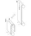
- FIG. 4 schematically shows the bending motion of the repeated bending test.
- the clamshell type cyclic bending tester is provided with a holding plate 3 composed of two sheets, to which a titanium alloy foil 1 is attached, and the holding plate is tilted to apply a corrective bending displacement to the titanium alloy foil 1.
- FIG. 4 shows state A with an opening angle of 180°, state B with an opening angle of about 90°, and state C with a closing angle of 0°.
- One of the two holding plates 3 is tilted while rotating around the drive shaft 4, the other holding plate maintains the same angle, and the corners of the upper surfaces of both holding plates are in contact with the titanium alloy foil.
- the two lines follow while keeping the distance constant as indicated by the dashed line in FIG.
- the titanium alloy foil can be repeatedly bent without applying a load other than bending.
- Yuasa System Equipment Co., Ltd., no-load clamshell bending tester, type DR11MR can be mentioned.
- the durability against repeated bending may be tested by incorporating it into an actual device.
- the titanium alloy foil is subjected to bending displacement forming an arc with a bending radius R.
- the bent portion may not form a complete arc.
- R of the outer peripheral surface of the titanium alloy foil when the part is regarded as an arc.
- the titanium alloy foil is cut into a size of 40 mm wide x 150 mm long, and the center of the long side and the width direction are measured so that the bending ridgeline direction.
- the width and length of the titanium alloy foil are measured on a scale with a minimum memory of 0.05 mm, and cut so as to have a tolerance range of ⁇ 0.5 mm.
- For the thickness use a single-sphere micrometer whose minimum reading value is micrometers or less, one side is flat and one side is spherical, and measure 10 points at different locations within the sample, and the average value is up to 0.1 ⁇ m. shall be taken.
- Gap 2R is set so that R/t is within ⁇ 2 of the target.
- the gap is measured using a limit gauge or vernier caliper, or by obtaining an image from the bending center axis direction at the closing angle of 0°, and measuring in millimeters to the first decimal place.
- both ends of the bent ridgeline should be polished with emery paper of #1500 or more before attaching the metal foil to the holding plate so that cracks do not form from the ends of the metal foil.
- the frequency of repeated bending that determines the bending speed is 1 Hz.
- R/t is a dimensionless quantity that has the same units for the numerator and denominator, and is an index that expresses the severity of bending in consideration of the stress and strain that the material receives. Even if R is the same, as the thickness (t) of the material increases, the stress and strain that the material receives increases. On the other hand, the material must have strength and rigidity according to its use.
- the preferred titanium alloy foil according to the present embodiment is 65 ⁇ R/t ⁇ 69 and the developed angle is 180°. .
- Repeated bending at 65 ⁇ R/t ⁇ 69 and an expansion angle of 180° is a preferable condition for defining the properties to be provided for the titanium alloy foil according to the present embodiment. It may be repeatedly bent at 30 to 250 degrees, more than 90 degrees, and 360 degrees or less (for example, a deployment angle of 135 degrees or more). Even when repeatedly bent at an R/t of 30 or more and 250 or less, more than 90° and 360° or less (for example, a deployment angle of 135° or more (135°, 180°, etc.)), when repeated 200,000 times, It is preferable that the length of cracks generated on the surface of the titanium alloy foil is 5 mm or less.
- R/t is less than 30, even foil that satisfies other conditions will have a large bending tendency or will not meet the required fatigue life (cracks will occur).
- R/t is greater than 250, even a conventional metal foil that does not meet the requirements of this embodiment can satisfy the bending habit and fatigue life. That is, the curvature and foil thickness required for foldable devices and rollable devices are outside the range, and general metal foils can be used.
- the permanent deformation (bend habit) after repeated bending is also used as an indicator of durability.
- bending is repeated, if the bending tendency in the bending direction is small, it is not a problem because it is corrected by the hinges and frames that make up the electronic device.
- the titanium alloy foil according to the present embodiment is used as a reinforcing material for light-emitting devices such as lighting and displays, which can be folded (bent) in two or rolled into a roll by adhering light-emitting elements on the foil surface. . These devices do not simply form curved surfaces, but are subjected to repeated bending with large curvatures.
- the organic EL element which is one of the light-emitting elements, is an element capable of high-definition display with high color rendering, and is used in displays of high-end televisions and mobile phones. Bending habits and breaking cracks in the reinforcing material deteriorate the quality of the display at that part, so high durability is required in particular. Therefore, a high tensile strength is required in a specific direction, specifically in the bending direction.
- the titanium alloy foil according to the present embodiment is not a substrate on which a light emitting element is directly formed, it does not need to be smooth as a surface. However, since the roughness measured in the bending direction affects the bending durability, it is preferable that the roughness be small. On the other hand, in order to prevent peeling of the adhesive that adheres the titanium alloy foil and the light emitting element, it is better to have a certain amount of unevenness that can be expected to have an anchor effect.
- the roughness of the titanium alloy foil according to the present embodiment is an arithmetic mean roughness Ra defined by JIS B 0601 (2001) of 0.010 ⁇ m or more and a maximum valley depth Rv of 0.180 ⁇ m or less. is preferred. Rv is more preferably 0.120 ⁇ m or less, even more preferably 0.100 ⁇ m or less.
- the reason why the upper limit of the roughness is the maximum valley depth is that the depth of the recesses has a greater effect on the durability against repeated bending than the height of the projections of the surface unevenness.
- the reason why the lower limit of the roughness is the arithmetic mean roughness is that when considering the adhesive strength of the adhesive, the average unevenness including peaks and valleys has an effect. From the viewpoint of durability, it is desirable that the roughness be as small as possible.
- Rv and Ra adopt the values measured by the stylus method according to JIS B 0601 (2001).
- the measurement conditions are a measurement length of 1.25 mm, a cutoff ( ⁇ c) of 0.25 mm, a cutoff ( ⁇ s) of 0.0025 mm, a stylus scanning speed of 0.3 mm/sec, and a measurement load of 0.7 mN.
- values using a cone with a radius of 2 ⁇ mR and a tip opening angle of 60° are adopted.
- Rv and Ra are obtained simultaneously in one measurement.
- Ra and Rv which are used as indexes in this embodiment, are obtained by measuring five or more different points on each surface of the titanium alloy foil and adopting the average value thereof.
- the roughness measured on the larger surface for Rv and the smaller surface for Ra is adopted as the surface unfavorable for performance. shall be
- the material that satisfies the durability requirements is mainly the ⁇ phase. It must be a ⁇ -type titanium alloy foil having Therefore, as described above, in the X-ray diffraction intensity obtained when X-ray diffraction is performed on the surface, the peak intensity of the 200 plane of the crystal of the body-centered cubic structure is the maximum peak intensity from other crystal structures. is 5.0 times or more.
- the titanium alloy foil according to the present embodiment particularly requires durability against repeated bending and is characterized by a small thickness, and the ratio of the phase different from the ⁇ phase is preferably small.
- the room-temperature stable phase of pure titanium is ⁇ -type titanium with a close-packed hexagonal crystal structure, and most titanium alloys generally used commercially are ⁇ -type titanium.
- the reason why a ⁇ -type titanium alloy foil mainly having a body-centered cubic structure is particularly preferable as the titanium alloy foil according to the present embodiment is that the durability can be increased when repeated bending is applied with a small bend. .
- strength is necessary, and the ⁇ -titanium alloy is easy to increase the cold rolling rate, and high strength can be obtained in a foil state.
- its Young's modulus is smaller than that of other high-strength metal foils such as stainless steel, and somewhat smaller than that of ⁇ -type titanium foil. Due to this feature, even if the strength is the same, the elastic limit is large with respect to a certain bending strain, and bending tendencies are less likely to occur when bent to a large curvature.
- Metal foil used as a reinforcing plate for light-emitting elements in foldable displays and rollable devices does not require a restoring force as a leaf spring when unbent, and rather a small one is preferable.
- a low Young's modulus of is suitable.
- Titanium alloy foil, which has a light specific gravity among metals, is also suitable from the viewpoint of reducing the weight of the device.
- the alloy system of the titanium alloy according to the present embodiment is not particularly limited as long as it is an alloy system that becomes a ⁇ -type titanium alloy mainly having a body-centered cubic structure, and the effect can be obtained regardless of the chemical composition.
- Mo equivalent (mass%) Mo + 0.67 ⁇ V + 0.44 ⁇ W + 0.28
- the Mo equivalent calculated by ⁇ Nb+0.22 ⁇ Ta+2.9 ⁇ Fe+1.6 ⁇ Cr ⁇ 1.0 ⁇ Al is preferably 5.0 (mass %) or more. More preferably, the Mo equivalent is 10.0 (mass%) or more.
- the element symbol in the formula is the content in mass% of each element contained in the titanium alloy)
- Ti-15V-3Cr-3Sn-3Al Ti-20V-4Al-1Sn, Ti-22V-4Al, Ti-15V-6Cr-4Al-1Fe, Ti-13V-11Cr- 3Al, Ti-3Al-8V-6Cr-4Mo-4Zr, Ti-4.5Fe-6.8Mo-1.5Al, Ti-8V-5Fe-1Al, Ti-16V-4Al, Ti-15Mo-5Zr, Ti- 15Mo-5Zr-3Al, T-15Mo-3Al, Ti-7.5V-8Cr-1.6Fe-3.5Sn-3Al, Ti-20V-4Al-1Sn, Ti-22V-4Al, Ti-10V-2Fe- 3Al, Ti-8Mo-8V-2Fe-3Al, Ti-11.5Mo-6Zr-4.5Sn and the like.
- Ti-15V-3Cr-3Sn-3Al is a representative value of the main alloy content of V: 15%, Cr: 3%, Sn: 3%, Al: 3%. , indicates a Ti alloy with the balance being Ti and impurities.
- the alloying elements used in these alloys are elements that act to stabilize the ⁇ -phase, which has a body-centered cubic structure, and improve strength, whereas the ⁇ -phase, which has a hexagonal close-packed structure, is stable at room temperature. be.
- a multicomponent alloy is selected because it is difficult to obtain sufficient phase stability and necessary strength by itself.
- Ti-36Nb-2Ta-3Zr-0.3O, Ti-47Nb-3Ta-4Zr-0.3O, Ti-34Nb-23Ta-11Zr-3V-0.3O, Ti-9Nb-12Ta-6Zr- 3V-0.3O is an alloy system with a large elastic range, and is suitable as the titanium alloy foil according to this embodiment.
- the composition of the above alloys is in mass %.
- Component values are representative values of essential elements, and may include manufacturing errors and unavoidable impurities.
- Ti-15V-3Cr-3Sn-3Al has, in mass%, V: 14.0 to 16.0%, Cr: 2.5 to 3.5%, Sn: 2.5 to 3.5%, Al: 2.5 to 3.5%, Fe: 1.00% or less, O: 0.25% or less, N: 0.15% or less, C: 0.15% or less , and the balance being Ti and impurities.
- vanadium, chromium, tin, and aluminum are used to stabilize the ⁇ phase at room temperature and facilitate cold working while ensuring strength.
- Iron (Fe), oxygen (O), nitrogen (N), and carbon (C) are elements that are likely to be contained as impurity elements, and managing the contents to a certain extent is effective for cost reduction.
- Iron is a ⁇ -phase stabilizing element, contributes to solid-solution strengthening, and has the effect of increasing strength.
- Oxygen, nitrogen, and carbon also contribute to solid-solution strengthening and have the effect of increasing strength.
- Ti-36Nb-2Ta-3Zr-0.3O is mass%, Nb: 33.0 to 38.5%, Ta: 1.5 to 2.5%, Zr: 2.5 ⁇ 3.5%, O: 0.05 to 1.3%, Fe: 1.00% or less, N: 0.15% or less, C: 0.15% or less, the balance being Ti and impurities It can be of a certain composition.
- the component ranges of niobium (Nb), tantalum (Ta), and zirconium (Zr) are each in this component range, so that the titanium alloy foil according to the present embodiment has a high strength and a large elastic strain exceeding 1%. is obtained.
- the preferred control ranges and reasons for iron, carbon, and nitrogen as impurity elements are the same as for Ti-15V-3Cr-3Sn-3Al.
- the reinforcing action of oxygen can be positively utilized.
- titanium alloys are, for example, ASTM Gr.6, AMS 4910, AMS 4926, AMS 4966, AMS 4919, AMS 4975, AMS 4976, ASTM Gr. 4977 specified titanium alloy.
- the chemical composition can be analyzed by known methods such as ICP-AES.
- the manufacturing method of the titanium alloy foil according to the present embodiment differs depending on the alloy system. It can be obtained by a manufacturing method in which cold rolling is performed after annealing. Preferred requirements for each step are described below.
- Softening annealing may be performed prior to cold rolling. Softening annealing reduces the hardness of the titanium alloy and facilitates cold rolling under the conditions described later, which is preferable. From this point of view, the softening annealing conditions are preferably such that the maximum heating temperature is 700° C. or higher, and the soaking time (holding time) at the maximum heating temperature is 5 seconds or longer for softening to a hardness that can be rolled. . The required time varies depending on the alloy system and the maximum heating temperature, but there is no problem as long as the hardness is sufficient for rolling. It is desirable to select the holding time according to the conditions of the alloy system to be produced and the maximum heating temperature.
- the soaking time is more preferably 30 seconds or more.
- the ⁇ phase and the ⁇ phase that causes embrittlement are precipitated by being significantly lower than the ⁇ transus temperature of the alloy system, and the target repetition Bending durability may not be obtained.
- the maximum heating temperature of the softening annealing exceeds 1000°C, the titanium alloy softens more than necessary, and the desired tensile strength cannot be obtained after cold rolling. Therefore, when performing softening annealing, the maximum heating temperature shall be 1000° C. or less.
- the maximum heating temperature when the maximum heating temperature is high, the crystal grain size becomes too large, and homogenization is not achieved, resulting in a decrease in flatness and an increase in roughness of the titanium alloy after cold rolling.
- the lower the maximum heating temperature the better. For example, it is 950° C. or less, or 900° C. or less.
- the soaking time exceeds 100 seconds, the crystal grain size becomes too large and homogenization is not achieved, resulting in a decrease in flatness and an increase in roughness of the titanium alloy after cold rolling. Therefore, the soaking time is set to 100 seconds or less.
- the heat treatment time can be controlled by the sheet threading speed or the like.
- Cold rolling In the cold rolling, a plate material subjected to softening annealing as necessary is subjected to cold rolling to obtain a titanium alloy foil having a thickness of 0.005 to 0.200 mm.
- the cumulative rolling reduction is set to 30% or more. Preferably it is 50% or more.
- the upper limit of the cumulative rolling reduction is not limited, rolling becomes difficult when the cumulative rolling reduction becomes high. Also, if the cumulative rolling reduction is too high, Rv may increase. Therefore, the cumulative rolling reduction may be 95% or less.
- Cold rolling may be temporarily interrupted and annealing may be performed, but in that case, the above cumulative rolling reduction is the cumulative rolling reduction after the final annealing (that is, the softening heat treatment).
- the number of passes since the roughness of the surface changes depending on the number of passes (the number of passes), it is preferable to control the number of passes when controlling the roughness. Specifically, when the number of passes is 5 or more, Rv can be reduced. Therefore, the number of passes is preferably five or more. More preferably, the number of passes is 25 or more. On the other hand, when the number of passes exceeds 40, Ra becomes small. It is believed that this is because Ra is reduced by pressing while slightly pressing down the surface. Therefore, by setting the number of passes to 40 or less, the maximum valley depth Ra can be set to 0.010 ⁇ m or more. In cold rolling, the roughness of the rolling rolls directly affects the roughness of the titanium alloy foil. Therefore, the rolling rolls are preferably bright rolls.
- Ra can be increased by using a dull roll, but by using a bright roll and setting the above-described predetermined number of passes, the maximum valley depth can be adjusted according to the conditions of a strength of 1000 MPa or more and an Rv of 0.180 ⁇ m or less.
- the thickness Ra can be controlled to be 0.010 ⁇ m or more. Oil marks are likely to be formed continuously in the TD direction perpendicular to the rolling direction.
- the rolling direction of the titanium alloy foil according to the present embodiment is preferably used as the bending direction of the foldable device. It has a big impact on durability.
- the sheet threading speed is set to 5 m/min.
- Rolling at a very low speed described below improves the discharge of rolling oil, so oil marks can be suppressed, and while obtaining a strength of 1000 MPa or more, the maximum valley depth Rv can be 0.180 ⁇ m or less, which is preferable. .
- foil manufacturing cold rolling After cold rolling (foil manufacturing cold rolling), heat treatment such as annealing is not performed. (as cold rolled) Heat treatment after cold rolling impairs the flatness of the foil. Moreover, a predetermined texture may not be obtained. In the production of foil, it is advantageous to produce as cold rolled. Moreover, if annealing is performed, there is a concern that the tensile strength may be lowered.
- the heat treatment conditions and cold rolling conditions are not uniquely determined because they vary depending on the rolling load, strip threading speed, and other capabilities and specifications of the manufacturing equipment, but are adjusted to the preferred strength, structure, and surface texture of the present invention.
- the display panel according to the present embodiment is obtained by attaching the light-emitting element to the titanium alloy foil obtained by the above-described method via an adhesive layer so that the light-emitting surface of the light-emitting element is the outermost surface. .
- the titanium alloy foil of the present invention will be described more specifically below while showing examples.
- the examples shown below are only examples of the titanium alloy foil of the present invention, and the flexible titanium alloy foil of the present invention is not limited to the examples shown below.
- a titanium slab having a predetermined chemical composition is hot-rolled, cold-rolled, and annealed to obtain a predetermined chemical composition ( ⁇ 153 alloy, ⁇ 3623 alloy, Ti—Cr , Ti-11.5Mo-6Zr-4.5Sn).
- a predetermined chemical composition ⁇ 153 alloy, ⁇ 3623 alloy, Ti—Cr , Ti-11.5Mo-6Zr-4.5Sn.
- commercially available plate materials with a thickness of 0.5 to 0.8 mm JIS G 4305: 2012 "Cold-rolled stainless steel plates and strips", SUS430, SUS316, SUS301 (all stainless steel plates), and , TR-270C, 6Al-4V, and Ti-6Al-6V-2Sn (these are titanium alloy plate materials)).
- the thickness of the foil was measured using a Mitutoyo single-ball digital micrometer, format: BMS-25MX, capable of measuring up to 1 ⁇ m, and the thickness was measured at 10 different locations and averaged. .
- the surface of the obtained foil is subjected to X-ray diffraction in the manner described above, and the peak intensity of the 200 plane, the 211 plane, and the 110 plane of the body-centered cubic structure crystal, and other The maximum peak intensity from the crystal structure of was obtained.
- the results are shown in Tables 5-8.
- the tensile strength of the obtained foil was measured.
- a test piece having a shape conforming to JIS No. 13B test piece having a length of 150 mm was cut out from the metal foil manufactured as described above, and a contact-type strain gauge with a gauge length of 50 mm was attached, and a crosshead speed of 50 mm/ min. was carried out at the speed of The test direction was the rolling (RD) direction.
- the load until breakage was monitored with a load cell, and the value obtained by dividing the maximum load by the cross-sectional area of the sample before the test was taken as the tensile strength.
- Tensile strength was taken as the average of values obtained by measuring 5 test pieces. The results are shown in Tables 5-8.
- the roughness (Ra, Rv) of the obtained foil was measured.
- arbitrary ranges of different points on the foil surface manufactured as described above are measured using a Tokyo Seimitsu stylus-type surface roughness measuring instrument (with a tabletop anti-vibration table), model: SURFCOM480B, using JISB0601 ( 2001).
- the measurement conditions were a measurement length of 1.25 mm, a cutoff ( ⁇ c) of 0.25 mm, a cutoff ( ⁇ s) of 0.0025 mm, a stylus scanning speed of 0.3 mm/sec, and a measurement load of 0.7 mN.
- the probe used was a cone with a tip radius of 2 ⁇ m and an opening angle of 60°.
- the direction of measurement was the rolling direction.
- the roughness curve is obtained from the contour curve, which is the displacement profile corresponding to the unevenness of the foil surface of the probe measured in one direction, and the arithmetic mean roughness ( Ra), the maximum valley depth (Rv) was derived.
- the measured values of Ra and Rv were measured at arbitrary 5 different points on the surface of the metal foil, and the average value of the 5 points was taken.
- Roughness measurement was performed on the front and back of the foil, and the smaller value for Ra and the larger value for Rv were taken as the roughness index of the foil. The results are shown in Tables 5-8.
- the obtained foil was subjected to a repeated bending test, and the bending durability was evaluated based on the presence or absence of fatigue cracks and the bending tendency when unbent.
- a sample for the repeated bending test was cut out from the manufactured foil with a size of 40 mm in width and 100 mm in length aligned in the length direction.
- a no-load clamshell bending tester, type DR11MR, manufactured by Yuasa System Co., Ltd. was used. With the longitudinal direction of the sample as the bending direction, the operation of bending and closing at the center by 180° and then returning and opening by 180° was repeated.
- the gap at the time of bending and closing the bending curvature can be changed. As shown in FIG. 4, by setting the gap to 2R, the bent portion with the bending radius R is formed. The cycle of repeated bending was set to 1 Hz. The test was performed until the number of repeated bending reached 200,000 times.
- the crack evaluation was A for a sample that did not generate any cracks
- the crack evaluation for a sample with a crack of 5 mm or more was D
- the maximum crack length was 3 mm or more and 5 mm.
- Crack evaluation was C for less than 1 mm
- crack evaluation B was for Cracks with maximum cracks of less than 3 mm.
- the maximum crack length was used as a criterion, and those with evaluation D were selected. It was regarded as failing, and the others were regarded as passing.
- the free opening angle remaining on the metal foil was measured by removing the test piece from the test jig so as not to apply a large force to the test piece.
- the opening angle changes due to its own weight.
- the image was taken with a digital camera, and the angle (bending habit) attached to the metal foil was measured using the image.
- the metal foil was measured by pressing plates from both sides so that the angle due to the bending habit of the metal foil did not change.
- the metal foil returned to the opening angle of 180° without bending habit evaluation A, 175° or more and less than 180° bending habit evaluation B, 170° or more and less than 175° bending habit evaluation C. , less than 170°, i.e., those with a bending habit evaluation of 10° or more were evaluated as D. Evaluation D was set as unacceptable.
- the X-ray diffraction intensity obtained when performing X-ray diffraction on the surface in the thickness range of 0.005 mm or more and 0.200 mm or less the peak intensity of the 200 plane of the body-centered cubic structure crystal is 5.0 times or more the maximum peak intensity from other crystal structures, and among the X-ray diffraction intensities, the X of the body-centered cubic crystal In line diffraction intensity, the peak intensity of the 200 plane or the peak intensity of the 211 plane is greater than the peak intensity of the 110 plane.
- the tensile strength is 1000 MPa or more and 1800 MPa or less, and the bending durability when repeatedly bending is performed is high.
- the foil is a stainless steel foil or the like and is not a predetermined titanium alloy foil.
- Sample Nos. 1 to 3 are stainless steel foils obtained using a stainless plate material
- Sample No. 4 is an ⁇ (non-body-centered cubic) type titanium foil, both of which had a crack evaluation of D.
- Sample No. 6 had an unsuitable texture (outside the scope of the present invention) and a low tensile strength due to insufficient cumulative reduction in cold rolling during foil production.
- Sample No. 14 had a thick titanium alloy foil. As a result, the crack evaluation was D.
- Sample No. 20 was subjected to a softening heat treatment, but the texture was unsuitable because the maximum heating temperature was low. As a result, the crack evaluation was D. Sample No. 21 had an unsuitable texture because the maximum heating temperature of the softening heat treatment was high. As a result, the crack evaluation was D. Also, the tensile strength was low. Sample Nos. 22 and 23 had unsuitable textures because the soaking time of the softening heat treatment was too long. As a result, the bending habit evaluation was D. Moreover, the tensile strength was also low. Sample No. 27 had an insufficient cumulative rolling reduction, and therefore had an unsuitable texture and a low tensile strength. Samples Nos.
- the present invention it is possible to provide a material titanium alloy foil with high bending durability.
- display panels for foldable electronic equipment (foldable devices) and rollable electronic equipment (rollable devices) equipped with thin, small, lightweight, and highly durable flexible light-emitting panels have been developed.
- display panels, and electronic devices such as portable terminals, televisions, etc. that can be folded and stowed with these display panels.
Landscapes
- Engineering & Computer Science (AREA)
- Chemical & Material Sciences (AREA)
- Mechanical Engineering (AREA)
- Organic Chemistry (AREA)
- Materials Engineering (AREA)
- Metallurgy (AREA)
- Physics & Mathematics (AREA)
- Microelectronics & Electronic Packaging (AREA)
- Manufacturing & Machinery (AREA)
- Thermal Sciences (AREA)
- Crystallography & Structural Chemistry (AREA)
- Optics & Photonics (AREA)
- Devices For Indicating Variable Information By Combining Individual Elements (AREA)
- Electroluminescent Light Sources (AREA)
- Metal Rolling (AREA)
Priority Applications (4)
| Application Number | Priority Date | Filing Date | Title |
|---|---|---|---|
| JP2023538684A JP7447362B2 (ja) | 2021-12-24 | 2022-12-22 | チタン合金箔及びディスプレーパネル、並びにディスプレーパネルの製造方法 |
| CN202280083666.0A CN118414447A (zh) | 2021-12-24 | 2022-12-22 | 钛合金箔和显示面板和显示面板的制造方法 |
| KR1020247020415A KR20240113520A (ko) | 2021-12-24 | 2022-12-22 | 티타늄 합금박 및 디스플레이 패널, 그리고 디스플레이 패널의 제조 방법 |
| US18/722,658 US20250143139A1 (en) | 2021-12-24 | 2022-12-22 | Titanium alloy foil, display panel, and method for manufacturing display panel |
Applications Claiming Priority (2)
| Application Number | Priority Date | Filing Date | Title |
|---|---|---|---|
| JP2021-210993 | 2021-12-24 | ||
| JP2021210993 | 2021-12-24 |
Publications (1)
| Publication Number | Publication Date |
|---|---|
| WO2023120631A1 true WO2023120631A1 (ja) | 2023-06-29 |
Family
ID=86902723
Family Applications (1)
| Application Number | Title | Priority Date | Filing Date |
|---|---|---|---|
| PCT/JP2022/047311 Ceased WO2023120631A1 (ja) | 2021-12-24 | 2022-12-22 | チタン合金箔及びディスプレーパネル、並びにディスプレーパネルの製造方法 |
Country Status (5)
| Country | Link |
|---|---|
| US (1) | US20250143139A1 (https=) |
| JP (1) | JP7447362B2 (https=) |
| KR (1) | KR20240113520A (https=) |
| CN (1) | CN118414447A (https=) |
| WO (1) | WO2023120631A1 (https=) |
Citations (4)
| Publication number | Priority date | Publication date | Assignee | Title |
|---|---|---|---|---|
| JPS6274062A (ja) * | 1985-09-27 | 1987-04-04 | Mitsubishi Metal Corp | Ti合金箔材の製造法 |
| JP2007501903A (ja) * | 2003-05-09 | 2007-02-01 | エイティーアイ・プロパティーズ・インコーポレーテッド | チタン−アルミニウム−バナジウム合金の加工及びそれによって製造した製品 |
| CN109371284A (zh) * | 2018-12-17 | 2019-02-22 | 河南师范大学 | 一种高性能立方织构金属基带及其制备方法 |
| CN113578967A (zh) * | 2021-06-27 | 2021-11-02 | 中国科学院金属研究所 | 一种550℃~650℃高温钛合金箔材的制备方法 |
Family Cites Families (3)
| Publication number | Priority date | Publication date | Assignee | Title |
|---|---|---|---|---|
| JP4316558B2 (ja) | 2005-06-28 | 2009-08-19 | 三星モバイルディスプレイ株式會社 | 有機発光表示装置 |
| CN102026743B (zh) | 2008-05-16 | 2015-02-11 | 新日铁住金高新材料株式会社 | 柔性显示器用不锈钢箔 |
| US9588549B2 (en) | 2014-02-28 | 2017-03-07 | Semiconductor Energy Laboratory Co., Ltd. | Electronic device |
-
2022
- 2022-12-22 US US18/722,658 patent/US20250143139A1/en active Pending
- 2022-12-22 CN CN202280083666.0A patent/CN118414447A/zh active Pending
- 2022-12-22 WO PCT/JP2022/047311 patent/WO2023120631A1/ja not_active Ceased
- 2022-12-22 JP JP2023538684A patent/JP7447362B2/ja active Active
- 2022-12-22 KR KR1020247020415A patent/KR20240113520A/ko active Pending
Patent Citations (4)
| Publication number | Priority date | Publication date | Assignee | Title |
|---|---|---|---|---|
| JPS6274062A (ja) * | 1985-09-27 | 1987-04-04 | Mitsubishi Metal Corp | Ti合金箔材の製造法 |
| JP2007501903A (ja) * | 2003-05-09 | 2007-02-01 | エイティーアイ・プロパティーズ・インコーポレーテッド | チタン−アルミニウム−バナジウム合金の加工及びそれによって製造した製品 |
| CN109371284A (zh) * | 2018-12-17 | 2019-02-22 | 河南师范大学 | 一种高性能立方织构金属基带及其制备方法 |
| CN113578967A (zh) * | 2021-06-27 | 2021-11-02 | 中国科学院金属研究所 | 一种550℃~650℃高温钛合金箔材的制备方法 |
Also Published As
| Publication number | Publication date |
|---|---|
| JPWO2023120631A1 (https=) | 2023-06-29 |
| KR20240113520A (ko) | 2024-07-22 |
| JP7447362B2 (ja) | 2024-03-11 |
| CN118414447A (zh) | 2024-07-30 |
| US20250143139A1 (en) | 2025-05-01 |
Similar Documents
| Publication | Publication Date | Title |
|---|---|---|
| KR101540163B1 (ko) | 가요성 디스플레이용 스테인리스 강박 | |
| JP5320638B2 (ja) | 圧延銅箔およびその製造方法 | |
| JP2009019232A (ja) | 圧延銅箔 | |
| JP2008106312A (ja) | 圧延銅箔およびその製造方法 | |
| JP4215093B2 (ja) | 圧延銅箔およびその製造方法 | |
| JP2011001622A (ja) | 圧延銅箔 | |
| WO2022210918A1 (ja) | 可撓性ステンレス箔および可撓性発光デバイス | |
| JP2010150597A (ja) | 圧延銅箔 | |
| JP2004256879A (ja) | 高い伸びを有する圧延銅箔 | |
| JP5161059B2 (ja) | 高強度で深絞り性に優れたチタン合金板およびチタン合金板の製造方法 | |
| JP7447362B2 (ja) | チタン合金箔及びディスプレーパネル、並びにディスプレーパネルの製造方法 | |
| KR20140004793A (ko) | 프레스 성형성과 강도의 밸런스 및 내식성이 우수한 순티타늄판, 및 그 제조 방법 | |
| JP5399759B2 (ja) | 高強度で曲げ加工性並びにプレス成形性に優れたチタン合金板およびチタン合金板の製造方法 | |
| JP5390852B2 (ja) | 圧延銅箔 | |
| JP5373941B1 (ja) | 圧延銅箔 | |
| CN103421977B (zh) | 轧制铜箔 | |
| KR101460931B1 (ko) | 압연 동박 | |
| WO1999062665A1 (fr) | Materiau revetu et son procede de fabrication | |
| JP2014019892A (ja) | 圧延銅箔 | |
| JP2023000682A (ja) | 圧延材および圧延材の製造方法 | |
| JP5631847B2 (ja) | 圧延銅箔 | |
| KR20130063444A (ko) | 압연동박 | |
| JP2008038170A (ja) | 圧延銅箔 | |
| JP7593530B2 (ja) | 圧延材 | |
| TWI392749B (zh) | 易壓延之合金材料 |
Legal Events
| Date | Code | Title | Description |
|---|---|---|---|
| WWE | Wipo information: entry into national phase |
Ref document number: 2023538684 Country of ref document: JP |
|
| 121 | Ep: the epo has been informed by wipo that ep was designated in this application |
Ref document number: 22911333 Country of ref document: EP Kind code of ref document: A1 |
|
| WWE | Wipo information: entry into national phase |
Ref document number: 202417044788 Country of ref document: IN |
|
| WWE | Wipo information: entry into national phase |
Ref document number: 202280083666.0 Country of ref document: CN |
|
| ENP | Entry into the national phase |
Ref document number: 20247020415 Country of ref document: KR Kind code of ref document: A |
|
| WWE | Wipo information: entry into national phase |
Ref document number: 1020247020415 Country of ref document: KR |
|
| WWE | Wipo information: entry into national phase |
Ref document number: 18722658 Country of ref document: US |
|
| NENP | Non-entry into the national phase |
Ref country code: DE |
|
| 122 | Ep: pct application non-entry in european phase |
Ref document number: 22911333 Country of ref document: EP Kind code of ref document: A1 |
|
| WWP | Wipo information: published in national office |
Ref document number: 18722658 Country of ref document: US |