WO2023120631A1 - Titanium alloy foil, display panel, and method for manufacturing display panel - Google Patents
Titanium alloy foil, display panel, and method for manufacturing display panel Download PDFInfo
- Publication number
- WO2023120631A1 WO2023120631A1 PCT/JP2022/047311 JP2022047311W WO2023120631A1 WO 2023120631 A1 WO2023120631 A1 WO 2023120631A1 JP 2022047311 W JP2022047311 W JP 2022047311W WO 2023120631 A1 WO2023120631 A1 WO 2023120631A1
- Authority
- WO
- WIPO (PCT)
- Prior art keywords
- titanium alloy
- alloy foil
- bending
- foil
- plane
- Prior art date
Links
- 239000011888 foil Substances 0.000 title claims abstract description 191
- 229910001069 Ti alloy Inorganic materials 0.000 title claims abstract description 146
- 238000004519 manufacturing process Methods 0.000 title claims description 21
- 238000000034 method Methods 0.000 title description 10
- 238000002441 X-ray diffraction Methods 0.000 claims abstract description 33
- 239000013078 crystal Substances 0.000 claims abstract description 33
- 239000012790 adhesive layer Substances 0.000 claims description 10
- 238000005452 bending Methods 0.000 description 130
- 238000005096 rolling process Methods 0.000 description 32
- 238000005097 cold rolling Methods 0.000 description 29
- 229910052751 metal Inorganic materials 0.000 description 24
- 239000002184 metal Substances 0.000 description 24
- 239000000956 alloy Substances 0.000 description 22
- 238000011156 evaluation Methods 0.000 description 22
- 229910045601 alloy Inorganic materials 0.000 description 21
- 239000000463 material Substances 0.000 description 21
- 238000010438 heat treatment Methods 0.000 description 20
- 239000000523 sample Substances 0.000 description 19
- 238000012360 testing method Methods 0.000 description 19
- 239000010935 stainless steel Substances 0.000 description 15
- 229910001220 stainless steel Inorganic materials 0.000 description 15
- RTAQQCXQSZGOHL-UHFFFAOYSA-N Titanium Chemical compound [Ti] RTAQQCXQSZGOHL-UHFFFAOYSA-N 0.000 description 13
- 238000000137 annealing Methods 0.000 description 13
- 230000009467 reduction Effects 0.000 description 13
- XEEYBQQBJWHFJM-UHFFFAOYSA-N iron Substances [Fe] XEEYBQQBJWHFJM-UHFFFAOYSA-N 0.000 description 12
- 239000000203 mixture Substances 0.000 description 12
- 239000010936 titanium Substances 0.000 description 12
- 230000001186 cumulative effect Effects 0.000 description 11
- 230000003014 reinforcing effect Effects 0.000 description 11
- 238000005259 measurement Methods 0.000 description 10
- 239000000126 substance Substances 0.000 description 10
- 229910052799 carbon Inorganic materials 0.000 description 9
- 239000011651 chromium Substances 0.000 description 9
- 239000012535 impurity Substances 0.000 description 9
- 229910052757 nitrogen Inorganic materials 0.000 description 9
- 239000000758 substrate Substances 0.000 description 9
- 229910052719 titanium Inorganic materials 0.000 description 9
- 229910052782 aluminium Inorganic materials 0.000 description 8
- 229910052804 chromium Inorganic materials 0.000 description 8
- 230000000694 effects Effects 0.000 description 7
- 229910052742 iron Inorganic materials 0.000 description 7
- 229910052760 oxygen Inorganic materials 0.000 description 7
- IJGRMHOSHXDMSA-UHFFFAOYSA-N Atomic nitrogen Chemical compound N#N IJGRMHOSHXDMSA-UHFFFAOYSA-N 0.000 description 6
- 239000000853 adhesive Substances 0.000 description 6
- 230000001070 adhesive effect Effects 0.000 description 6
- 239000010955 niobium Substances 0.000 description 5
- 239000012779 reinforcing material Substances 0.000 description 5
- 238000002791 soaking Methods 0.000 description 5
- 238000009864 tensile test Methods 0.000 description 4
- 229910052718 tin Inorganic materials 0.000 description 4
- 229910052720 vanadium Inorganic materials 0.000 description 4
- OKTJSMMVPCPJKN-UHFFFAOYSA-N Carbon Chemical compound [C] OKTJSMMVPCPJKN-UHFFFAOYSA-N 0.000 description 3
- QVGXLLKOCUKJST-UHFFFAOYSA-N atomic oxygen Chemical compound [O] QVGXLLKOCUKJST-UHFFFAOYSA-N 0.000 description 3
- 238000006073 displacement reaction Methods 0.000 description 3
- 229910052758 niobium Inorganic materials 0.000 description 3
- 239000003921 oil Substances 0.000 description 3
- 239000001301 oxygen Substances 0.000 description 3
- 230000002093 peripheral effect Effects 0.000 description 3
- 238000003825 pressing Methods 0.000 description 3
- 238000004439 roughness measurement Methods 0.000 description 3
- 229910052715 tantalum Inorganic materials 0.000 description 3
- 229910052726 zirconium Inorganic materials 0.000 description 3
- 229910001040 Beta-titanium Inorganic materials 0.000 description 2
- XAGFODPZIPBFFR-UHFFFAOYSA-N aluminium Chemical compound [Al] XAGFODPZIPBFFR-UHFFFAOYSA-N 0.000 description 2
- 238000011161 development Methods 0.000 description 2
- 230000005484 gravity Effects 0.000 description 2
- 238000000265 homogenisation Methods 0.000 description 2
- 239000007769 metal material Substances 0.000 description 2
- 150000002739 metals Chemical class 0.000 description 2
- 239000010731 rolling oil Substances 0.000 description 2
- 239000006104 solid solution Substances 0.000 description 2
- 238000005482 strain hardening Methods 0.000 description 2
- 238000005728 strengthening Methods 0.000 description 2
- 230000035882 stress Effects 0.000 description 2
- 229910000967 As alloy Inorganic materials 0.000 description 1
- VYZAMTAEIAYCRO-UHFFFAOYSA-N Chromium Chemical compound [Cr] VYZAMTAEIAYCRO-UHFFFAOYSA-N 0.000 description 1
- 229910000831 Steel Inorganic materials 0.000 description 1
- 241001422033 Thestylus Species 0.000 description 1
- ATJFFYVFTNAWJD-UHFFFAOYSA-N Tin Chemical compound [Sn] ATJFFYVFTNAWJD-UHFFFAOYSA-N 0.000 description 1
- 230000005856 abnormality Effects 0.000 description 1
- 238000005275 alloying Methods 0.000 description 1
- 230000015572 biosynthetic process Effects 0.000 description 1
- 230000008859 change Effects 0.000 description 1
- 230000000052 comparative effect Effects 0.000 description 1
- 125000004122 cyclic group Chemical group 0.000 description 1
- 230000006378 damage Effects 0.000 description 1
- 229910001651 emery Inorganic materials 0.000 description 1
- 230000006355 external stress Effects 0.000 description 1
- 230000002349 favourable effect Effects 0.000 description 1
- 239000010408 film Substances 0.000 description 1
- 238000003384 imaging method Methods 0.000 description 1
- 238000002354 inductively-coupled plasma atomic emission spectroscopy Methods 0.000 description 1
- 239000010410 layer Substances 0.000 description 1
- 230000007246 mechanism Effects 0.000 description 1
- GUCVJGMIXFAOAE-UHFFFAOYSA-N niobium atom Chemical compound [Nb] GUCVJGMIXFAOAE-UHFFFAOYSA-N 0.000 description 1
- 239000004033 plastic Substances 0.000 description 1
- 238000005498 polishing Methods 0.000 description 1
- 239000000843 powder Substances 0.000 description 1
- 238000009877 rendering Methods 0.000 description 1
- 238000005070 sampling Methods 0.000 description 1
- VSZWPYCFIRKVQL-UHFFFAOYSA-N selanylidenegallium;selenium Chemical compound [Se].[Se]=[Ga].[Se]=[Ga] VSZWPYCFIRKVQL-UHFFFAOYSA-N 0.000 description 1
- 229920002379 silicone rubber Polymers 0.000 description 1
- 239000004945 silicone rubber Substances 0.000 description 1
- 230000000087 stabilizing effect Effects 0.000 description 1
- 239000010959 steel Substances 0.000 description 1
- 238000003860 storage Methods 0.000 description 1
- 230000003746 surface roughness Effects 0.000 description 1
- GUVRBAGPIYLISA-UHFFFAOYSA-N tantalum atom Chemical compound [Ta] GUVRBAGPIYLISA-UHFFFAOYSA-N 0.000 description 1
- 239000010409 thin film Substances 0.000 description 1
- LEONUFNNVUYDNQ-UHFFFAOYSA-N vanadium atom Chemical compound [V] LEONUFNNVUYDNQ-UHFFFAOYSA-N 0.000 description 1
- 238000004736 wide-angle X-ray diffraction Methods 0.000 description 1
- 230000037303 wrinkles Effects 0.000 description 1
Images


Classifications
-
- B—PERFORMING OPERATIONS; TRANSPORTING
- B21—MECHANICAL METAL-WORKING WITHOUT ESSENTIALLY REMOVING MATERIAL; PUNCHING METAL
- B21B—ROLLING OF METAL
- B21B1/00—Metal-rolling methods or mills for making semi-finished products of solid or profiled cross-section; Sequence of operations in milling trains; Layout of rolling-mill plant, e.g. grouping of stands; Succession of passes or of sectional pass alternations
- B21B1/40—Metal-rolling methods or mills for making semi-finished products of solid or profiled cross-section; Sequence of operations in milling trains; Layout of rolling-mill plant, e.g. grouping of stands; Succession of passes or of sectional pass alternations for rolling foils which present special problems, e.g. because of thinness
-
- B—PERFORMING OPERATIONS; TRANSPORTING
- B21—MECHANICAL METAL-WORKING WITHOUT ESSENTIALLY REMOVING MATERIAL; PUNCHING METAL
- B21B—ROLLING OF METAL
- B21B3/00—Rolling materials of special alloys so far as the composition of the alloy requires or permits special rolling methods or sequences ; Rolling of aluminium, copper, zinc or other non-ferrous metals
-
- C—CHEMISTRY; METALLURGY
- C22—METALLURGY; FERROUS OR NON-FERROUS ALLOYS; TREATMENT OF ALLOYS OR NON-FERROUS METALS
- C22C—ALLOYS
- C22C14/00—Alloys based on titanium
-
- C—CHEMISTRY; METALLURGY
- C22—METALLURGY; FERROUS OR NON-FERROUS ALLOYS; TREATMENT OF ALLOYS OR NON-FERROUS METALS
- C22F—CHANGING THE PHYSICAL STRUCTURE OF NON-FERROUS METALS AND NON-FERROUS ALLOYS
- C22F1/00—Changing the physical structure of non-ferrous metals or alloys by heat treatment or by hot or cold working
- C22F1/16—Changing the physical structure of non-ferrous metals or alloys by heat treatment or by hot or cold working of other metals or alloys based thereon
- C22F1/18—High-melting or refractory metals or alloys based thereon
-
- C—CHEMISTRY; METALLURGY
- C22—METALLURGY; FERROUS OR NON-FERROUS ALLOYS; TREATMENT OF ALLOYS OR NON-FERROUS METALS
- C22F—CHANGING THE PHYSICAL STRUCTURE OF NON-FERROUS METALS AND NON-FERROUS ALLOYS
- C22F1/00—Changing the physical structure of non-ferrous metals or alloys by heat treatment or by hot or cold working
Definitions
- the present invention relates to a titanium alloy foil and display panel, and a method of manufacturing the display panel.
- Bendable light-emitting elements especially organic EL elements
- foldable devices in which the screen itself can be folded
- rollable devices which can be rolled up and stored
- foldable devices When there is no need to distinguish between a device and a rollable device, both may be collectively called a foldable device).
- the organic EL element Since the organic EL element itself has no rigidity, it often needs a reinforcing plate on its back surface.
- the reinforcing plate is attached to the light-emitting element using an adhesive or the like, and since it is bent together with the light-emitting element, it must be flexible, so a thin stainless steel plate or stainless steel foil is mainly selected. What is required for such a reinforcing plate is bending durability. Specifically, it is required that the steel should not develop a bending habit in repeated bending, and should not crack or break due to metal fatigue. Therefore, the required properties are similar to those required for spring materials, but unlike spring materials, restoring force is not necessarily required.
- Patent Document 1 a stainless steel foil with an average arithmetic mean roughness (Ra) of 50 nm or less in the rolling direction of the foil and in the direction perpendicular to the rolling direction is devised as a stainless steel foil used for flexible display substrates.
- the curvature in this invention is assumed to be a relatively large curvature from the scope of the claims.
- a substrate made of stainless steel foil with a thin insulating film on which a circuit is formed is required to have smoothness so as not to impair the resolution of the display.
- Patent Document 2 proposes an organic light emitting device including a flexible conductive substrate made of stainless steel or titanium and a thin film transistor formed on the conductive substrate.
- this light emitting device relates to a system that applies a bias to the conductive substrate.
- the property required for flexible substrates is conductivity, and repeated bending is not assumed.
- Patent Document 3 describes that a titanium alloy material is used as a reinforcing material for a light-emitting panel such as an organic EL.
- a titanium alloy material is used as a reinforcing material for a light-emitting panel such as an organic EL.
- it is described on the same level as currently used stainless steel, plastic, aluminum, and silicone rubber, which generally have low strength, and is not expected to be used for severe repeated bending, which is required in recent years.
- these electronic devices are required to be thinner and lighter, as in the case of clamshell type, slide type, and tablet mobile phone terminals.
- the curvature required for durability is becoming more and more severe. In other words, more precise requirements are required for the metal materials required for the reinforcing plate, and the current materials are becoming unable to meet these requirements.
- the present invention provides a material with higher bending durability to replace the metal foil currently used as a backing reinforcing material for light-emitting elements such as display panels of foldable devices.
- a material which does not generate a large fatigue crack even when it is repeatedly bent at a small bending radius (large curvature) and a large bending angle, and which has a small bending habit when it is re-bent.
- Another object of the present invention is to provide a display panel using such a material and a method for manufacturing the display panel.
- the present inventors have studied the use of a titanium alloy foil, which has a high specific strength among metals, as a reinforcing material from the viewpoint of reducing the weight of the device. As described above, in the prior art, titanium alloy foils have not been considered for applications requiring severe repeated bending. As a result of further studies, the inventors of the present invention found that controlling the texture of the titanium alloy foil to a predetermined state greatly improves the bending durability.
- the present invention has been made in view of the above findings.
- the gist of the present invention is as follows.
- the titanium alloy foil according to one aspect of the present invention has a thickness t of 0.005 mm or more and 0.200 mm or less, and when the surface is subjected to X-ray diffraction, In the obtained X-ray diffraction intensity, the peak intensity of the 200 plane of the body-centered cubic structure crystal is 5.0 times or more the maximum peak intensity from other crystal structures, and among the X-ray diffraction intensities, the body In the X-ray diffraction intensity of the centered cubic structure crystal, the peak intensity of the 200 plane or the peak intensity of the 211 plane is greater than the peak intensity of the 110 plane, and the tensile strength is 1000 MPa or more and 1800 MPa or less.
- the peak intensity of the 200 plane may be higher than all other peak intensities.
- the surface arithmetic mean roughness Ra may be 0.010 ⁇ m or more, and the maximum valley depth Rv may be 0.180 ⁇ m or less.
- the surface arithmetic mean roughness Ra may be 0.010 ⁇ m or more, and the maximum valley depth Rv may be 0.180 ⁇ m or less.
- a display panel comprises the titanium alloy foil according to any one of [1] to [4] above, and an adhesive layer provided on the surface of the titanium alloy foil. and a light emitting element provided on the surface of the adhesive layer.
- the light-emitting element may be an organic EL display element.
- a method of manufacturing a display panel according to another aspect of the present invention includes: a titanium alloy foil according to any one of [1] to [4]; and attaching the light emitting element via an adhesive layer.
- a titanium alloy foil with high bending durability By using this titanium alloy foil, display panels for foldable electronic equipment (foldable devices) and rollable electronic equipment (rollable devices) equipped with thin, small, lightweight, and highly durable flexible light-emitting panels have been developed. display panels and electronic devices such as foldable and retractable mobile terminals and televisions having these display panels. Further, according to the above aspect of the present invention, it is possible to provide a display panel comprising a titanium alloy foil with high bending durability and light emitting elements, and a method of manufacturing the same.
- FIG. 2 illustrates an example of a display panel for a foldable electronic device
- FIG. 1 shows an example of a display panel for a rollable electronic device
- FIG. 1 shows an example of a display panel for a rollable electronic device
- It is a figure which shows a clamshell type
- the titanium alloy foil according to one embodiment of the present invention (titanium alloy foil according to this embodiment) has a thickness t of 0.005 mm or more and 0.200 mm or less, and
- the peak intensity of the 200 plane of the crystal of the body-centered cubic structure is 5.0 times or more the maximum peak intensity from other crystal structures, and the X Among the line diffraction intensities, in the X-ray diffraction intensity of the body-centered cubic structure crystal, the peak intensity of the 200 plane or the peak intensity of the 211 plane is greater than the peak intensity of the 110 plane, and the tensile strength is 1000 MPa. Above, it is below 1800MPa.
- the titanium alloy foil according to the present embodiment is assumed to be applied to a display panel.
- the titanium alloy foil according to the present embodiment is used, the titanium alloy foil according to the present embodiment, the adhesive layer provided on the surface of the titanium alloy foil, and the light emitting layer provided on the surface of the adhesive layer It is possible to obtain a display panel (hereinafter sometimes referred to as a display panel according to the present embodiment) having the elements. I will explain each.
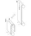
- FIGS. 1 to 3 Examples of the display panel according to this embodiment are shown in FIGS. 1 to 3.
- FIG. 1 is an example of a display panel for foldable electronic equipment
- FIGS. 2 and 3 are examples of display panels for rollable electronic equipment. All of these figures are simplified for the sake of explanation.
- the titanium alloy foil 1 according to this embodiment and a light-emitting element 2 such as an organic EL element are bonded together face-to-face using an adhesive or the like (not shown). Become.
- the light-emitting element, the adhesive, and the like are not limited, and known ones may be used.
- the light-emitting element is, for example, an organic EL display element.
- the light emitting element 2 and the titanium alloy foil 1 are attached together so that the light emitting element 2 is on the inside of the bend, but the light emitting element 2 may be attached to the outside of the titanium alloy foil 1.
- the display panel is subjected to repeated bending in a completely closed state and a 180° open state. That is, the titanium alloy foil included in the display panel is also subjected to repeated bending in the completely closed state and the 180° open state.
- the repeated bending angle of the display panel (in the case of titanium alloy foil, the repeated bending angle of the titanium alloy foil) is referred to as the "development angle”.
- the minimum closing angle is 0° and the maximum opening angle is 360°. Therefore, the range of deployment angles is 0° or more and 360° or less. In the case of FIG. 1, the closing angle is 0°, the opening angle is 180°, and the deployment angle is 180°.
- the opening angle need not be 180°, and the opening angle may be up to about 135° in view of the visibility of the display.
- the cross section of the titanium alloy foil 1 is bent into an arc shape with a bending radius R at the bent location.
- the "bending radius R" defined in this embodiment is the center axis of bending and the titanium It is defined as the radius of the outer peripheral surface of the titanium alloy foil where the curvature given to the titanium alloy foil is the largest when the outer curved portion of the alloy foil is approximated to an arc.
- R the thickness of the electronic device in a folded state can be reduced.
- a display panel using the titanium alloy foil 1 according to the present embodiment is useful because even if the bending radius R is small, a large fatigue crack does not occur and the bending habit when it is bent back is small.
- the line forming the crease (dotted line in FIG. 1) is called the ridge line, and the direction of the ridge line is called the "ridge line direction".
- the direction of the ridge is parallel to the central axis of bending.
- the foil is flattened, the direction perpendicular to the ridge line in the plane is called the "bending direction”.
- a display panel for a rollable device as shown in FIGS. 2 and 3 has a closing angle of 0°, an opening angle of 180°, and an opening angle of 180° (for titanium alloy foil, the closing angle is 0° and the opening angle is 180°). The angle is 180° and the deployment angle is 180°).
- the curvature is constant, and the constant radius is defined as the bending radius R (mm).
- the smallest bending radius of the outer peripheral surface of the titanium alloy foil is defined as R (mm). If the bending radius R can be reduced, the display panel for a slide-type rollable device as shown in FIG. 2 can be made thinner, and a roll-type rollable display as shown in FIG. 3 can be used to reduce the storage space. be able to.
- Titanium alloys have a lower density than stainless steel and are effective in reducing weight. Titanium alloy foils, which have sufficient repeated bending properties even under severe conditions, are useful as materials for small, lightweight display panels. .
- titanium alloy foil The titanium alloy foil according to this embodiment will be described in detail below. As described above, the titanium alloy foil according to this embodiment can be used as a material (reinforcing plate for light emitting elements) of the display panel according to this embodiment.
- the thickness of metal foil used as a reinforcing plate for light-emitting elements in foldable displays and rollable devices is 0.200 mm (200 ⁇ m) or less, mostly 0.150 mm or less, particularly 0.050 mm or less. be. Therefore, the thickness of the titanium alloy foil according to this embodiment is set to 0.200 mm (200 ⁇ m) or less. It is preferably 0.150 mm or less, more preferably 0.100 mm or less, still more preferably 0.070 mm or less, and still more preferably 0.050 mm or less.
- titanium foil with a thickness of 0.200 mm or less has been used as a leaf spring that requires a restoring force and has a deployment angle of over 90° in repeated bending due to its thickness and low Young's modulus, which is a characteristic of titanium.
- Young's modulus which is a characteristic of titanium.
- a titanium alloy foil having a strength of 1000 MPa or more and having a body-centered cubic structure as a main body has a thickness of 0.200 mm or less. , and has extremely excellent durability against repeated bending with a small bending radius (large curvature).
- the titanium alloy foil according to the present embodiment is a titanium alloy foil with a thickness of 0.200 mm or less, which has the necessary flexibility for repeated bending at an expansion angle of more than 90° in the plane of the foil.
- the thickness of the titanium alloy foil according to this embodiment is 0.005 mm or more for the purpose of reinforcing the light emitting element.
- the thickness is more preferably 0.010 mm or more, still more preferably 0.020 mm or more.
- the peak intensity of the 200 plane of the body-centered cubic structure crystal is 5.0 times or more the maximum peak intensity from other crystal structures.
- the titanium alloy foil according to the present embodiment has a texture from the viewpoint of durability against repeated bending. Specifically, when the X-ray diffraction intensity of the titanium alloy foil according to the present embodiment is measured from the foil surface perpendicular to the thickness direction, the peak intensity from the 200 plane from the titanium alloy having a body-centered cubic structure is is at least 5.0 times the maximum peak intensity from titanium alloy phases with other crystal structures.
- the material that satisfies the durability requirements is the ⁇ -type. of titanium alloy foil. It does not necessarily have to be a single phase, and may contain other phases such as an ⁇ phase with a close-packed hexagonal structure and a very small amount of an ⁇ phase, but the ⁇ phase must be the main component.
- the peak intensity from the 200 plane from the titanium alloy having the body-centered cubic structure is greater than the maximum peak intensity from the titanium alloy phases having other crystal structures indicates that the area ratio of the ⁇ phase is large.
- the peak intensity of the 200 plane is 5.0 times the maximum peak intensity from other crystal structures, as an indicator that it is ⁇ -type titanium having a sufficient ⁇ -phase area ratio. Suppose that it is above.
- the peak intensity of the 200 plane or the peak intensity of the 211 plane is greater than the peak intensity of the 110 plane>
- the ⁇ 001 ⁇ ⁇ 110> texture is developed (when the peak strength of the 200 plane is large), the strength and elongation in the rolling direction increase, and the elastic limit against strain increases, so that it is resistant to repeated bending. Increased durability.
- the Young's modulus in the in-plane direction of the foil is generally high, especially in the rolling direction (RD).
- the Young's modulus increases in the direction (TD direction) perpendicular to the (TD) direction.
- the fact that orientations with high Young's modulus are concentrated in the in-plane direction is suitable for use in which soft light-emitting elements are bonded together to compensate for rigidity.
- the degree of texture formation is defined by the results of the wide-angle X-ray diffraction method, the X-ray diffraction intensity of ⁇ titanium alloys having random orientations such as powders is highest from the 110 plane.
- the thickness direction of the titanium alloy foil is perpendicular to the thickness direction.
- the peak intensity from the 200th plane the peak intensity of the 200th plane
- At least one of the peak intensities is greater than the peak intensity from the 110 plane (the peak intensity of the 110 plane). This can be said to be an index indicating that the number of crystal grains oriented in the 110 direction within the foil surface has increased.
- the texture can be obtained by foil rolling.
- the titanium alloy foil according to the present embodiment has a body-centered cubic structure, and a rolling texture in which ⁇ 001 ⁇ 110> and ⁇ 112 ⁇ 110> are developed can be obtained by intense cold rolling.
- the peak intensity of the 200 plane is greater than all other peak intensities> Moreover, it is preferable that the titanium alloy foil according to the present embodiment has the highest peak strength from the 200 plane. This indicates that the ⁇ 001 ⁇ 110> texture is more developed, and from the orientation relationship, the 110 orientation is accumulated not only in the rolling direction but also in the TD direction. Although the detailed mechanism is unknown, when the peak strength of the 200 plane is the highest, the bending durability is further improved. As described above, it is possible to obtain a rolling texture in which ⁇ 001 ⁇ ⁇ 110> and ⁇ 112 ⁇ ⁇ 110> are developed by strong cold rolling. strength is higher.
- Each X-ray diffraction peak intensity (peak intensity of 200 plane, peak intensity of 211 plane and peak intensity of 110 plane of body-centered cubic structure crystal, and maximum peak intensity from other crystal structures) is determined by the following method. Measure. A rectangular test piece measuring 10 mm in the width direction and 13 mm in the rolling (RD) direction is sampled from the titanium alloy foil, and this test piece is subjected to X-ray diffraction using a wide-angle XRD method (Cu tube, 40 kV, 150 mA). . It is not necessary to consider the front and back. For the measurement, RINT1500 (manufactured by Rigaku) or equivalent is used as a goniometer. Do not use filters or incident black and white.
- the divergence and scattering slits are both 1G
- the light receiving slit is 10.15 mm
- the monochromatic light receiving slit is 0.8 mm.
- the imaging conditions are a scan speed of 5°/min, a sampling width of 0.02°, and a scanning range of 10 to 100°.
- ⁇ Tensile strength 1000 MPa or more and 1800 MPa or less>
- the strength is anisotropic in the in-plane direction of the titanium alloy foil
- the repeated bending direction during use is limited to the direction in which a tensile strength of 1000 MPa or more can be obtained.
- the titanium alloy foil according to this embodiment needs to have a tensile strength of 1000 MPa or more in the bending direction. This is a necessary condition for both bending habit and destruction against repeated bending, and is especially essential for suppressing bending habit.
- the Young's modulus of titanium alloy foil is almost the same, the presence or absence of bending habits can be directly determined by the strength of the yield strength. Since there is a possibility, in this embodiment, the tensile strength (maximum strength) is defined.
- the tensile strength of the titanium alloy foil according to this embodiment is 1000 MPa or more, preferably 1100 MPa or more.
- the upper limit of the tensile strength is not particularly limited, but if it exceeds 1800 MPa, foil rolling becomes difficult, so from the viewpoint of manufacturing, the upper limit may be 1800 MPa.
- the strength of the titanium alloy foil according to this embodiment is the value of tensile strength obtained in a tensile test.
- a JIS No. 13B test piece is used for the tensile test. The test was carried out at a crosshead speed of 50 mm / min while reading the load applied to the load cell according to JIS2241:2011 "Metal material tensile test method". Tensile strength is obtained by dividing the area by the area.
- the titanium alloy foil according to the present embodiment has high durability against repeated bending because the texture and tensile strength are controlled as described above. Assuming that the titanium alloy foil according to the present embodiment is applied to the display panel of a foldable device such as a mobile phone as described above, the titanium alloy foil according to the present embodiment can be repeatedly bent at a deployment angle of 180°. It is also preferable to have durability against More specifically, the bending radius in mm is R, and the R and t are bent 180° in a range satisfying 65 ⁇ R / t ⁇ 69, and then returned to 0°, which was repeated 200,000 times.
- the length of cracks generated on the surface of the titanium alloy foil is 5 mm or less, and the bending habit is 170° or more in terms of opening angle when external stress is removed.
- the opening angle is more preferably 175° or more, and more preferably 180° with no bending tendency.
- the length of the crack defined here means the length of the longest crack when multiple cracks occur.
- the titanium alloy foil according to this embodiment is used integrally by bonding with a flexible light-emitting element represented by an organic EL element used in a foldable device. If there is a crack on the surface of the bent portion of the titanium alloy foil, a large amount of deformation will occur locally, causing an abnormality in the display of the light-emitting element, and in some cases, it may be damaged. Therefore, although it is desirable that cracks do not occur, a maximum of 5 mm is permissible due to the cushioning effect of the adhesive layer between the light emitting element and the titanium alloy foil.
- Foldable devices are expected to become smaller, thinner, and lighter in the future. It is preferable that cracks introduced into the surface of the titanium alloy foil be 5 mm or less when a repeated bending test is performed.
- the repeated bending test of the titanium alloy foil is performed using a clamshell type repeated bending tester under conditions of a closing angle of 0° and an opening angle of 180°.
- FIG. 4 schematically shows the bending motion of the repeated bending test.
- the clamshell type cyclic bending tester is provided with a holding plate 3 composed of two sheets, to which a titanium alloy foil 1 is attached, and the holding plate is tilted to apply a corrective bending displacement to the titanium alloy foil 1.
- FIG. 4 shows state A with an opening angle of 180°, state B with an opening angle of about 90°, and state C with a closing angle of 0°.
- One of the two holding plates 3 is tilted while rotating around the drive shaft 4, the other holding plate maintains the same angle, and the corners of the upper surfaces of both holding plates are in contact with the titanium alloy foil.
- the two lines follow while keeping the distance constant as indicated by the dashed line in FIG.
- the titanium alloy foil can be repeatedly bent without applying a load other than bending.
- Yuasa System Equipment Co., Ltd., no-load clamshell bending tester, type DR11MR can be mentioned.
- the durability against repeated bending may be tested by incorporating it into an actual device.
- the titanium alloy foil is subjected to bending displacement forming an arc with a bending radius R.
- the bent portion may not form a complete arc.
- R of the outer peripheral surface of the titanium alloy foil when the part is regarded as an arc.
- the titanium alloy foil is cut into a size of 40 mm wide x 150 mm long, and the center of the long side and the width direction are measured so that the bending ridgeline direction.
- the width and length of the titanium alloy foil are measured on a scale with a minimum memory of 0.05 mm, and cut so as to have a tolerance range of ⁇ 0.5 mm.
- For the thickness use a single-sphere micrometer whose minimum reading value is micrometers or less, one side is flat and one side is spherical, and measure 10 points at different locations within the sample, and the average value is up to 0.1 ⁇ m. shall be taken.
- Gap 2R is set so that R/t is within ⁇ 2 of the target.
- the gap is measured using a limit gauge or vernier caliper, or by obtaining an image from the bending center axis direction at the closing angle of 0°, and measuring in millimeters to the first decimal place.
- both ends of the bent ridgeline should be polished with emery paper of #1500 or more before attaching the metal foil to the holding plate so that cracks do not form from the ends of the metal foil.
- the frequency of repeated bending that determines the bending speed is 1 Hz.
- R/t is a dimensionless quantity that has the same units for the numerator and denominator, and is an index that expresses the severity of bending in consideration of the stress and strain that the material receives. Even if R is the same, as the thickness (t) of the material increases, the stress and strain that the material receives increases. On the other hand, the material must have strength and rigidity according to its use.
- the preferred titanium alloy foil according to the present embodiment is 65 ⁇ R/t ⁇ 69 and the developed angle is 180°. .
- Repeated bending at 65 ⁇ R/t ⁇ 69 and an expansion angle of 180° is a preferable condition for defining the properties to be provided for the titanium alloy foil according to the present embodiment. It may be repeatedly bent at 30 to 250 degrees, more than 90 degrees, and 360 degrees or less (for example, a deployment angle of 135 degrees or more). Even when repeatedly bent at an R/t of 30 or more and 250 or less, more than 90° and 360° or less (for example, a deployment angle of 135° or more (135°, 180°, etc.)), when repeated 200,000 times, It is preferable that the length of cracks generated on the surface of the titanium alloy foil is 5 mm or less.
- R/t is less than 30, even foil that satisfies other conditions will have a large bending tendency or will not meet the required fatigue life (cracks will occur).
- R/t is greater than 250, even a conventional metal foil that does not meet the requirements of this embodiment can satisfy the bending habit and fatigue life. That is, the curvature and foil thickness required for foldable devices and rollable devices are outside the range, and general metal foils can be used.
- the permanent deformation (bend habit) after repeated bending is also used as an indicator of durability.
- bending is repeated, if the bending tendency in the bending direction is small, it is not a problem because it is corrected by the hinges and frames that make up the electronic device.
- the titanium alloy foil according to the present embodiment is used as a reinforcing material for light-emitting devices such as lighting and displays, which can be folded (bent) in two or rolled into a roll by adhering light-emitting elements on the foil surface. . These devices do not simply form curved surfaces, but are subjected to repeated bending with large curvatures.
- the organic EL element which is one of the light-emitting elements, is an element capable of high-definition display with high color rendering, and is used in displays of high-end televisions and mobile phones. Bending habits and breaking cracks in the reinforcing material deteriorate the quality of the display at that part, so high durability is required in particular. Therefore, a high tensile strength is required in a specific direction, specifically in the bending direction.
- the titanium alloy foil according to the present embodiment is not a substrate on which a light emitting element is directly formed, it does not need to be smooth as a surface. However, since the roughness measured in the bending direction affects the bending durability, it is preferable that the roughness be small. On the other hand, in order to prevent peeling of the adhesive that adheres the titanium alloy foil and the light emitting element, it is better to have a certain amount of unevenness that can be expected to have an anchor effect.
- the roughness of the titanium alloy foil according to the present embodiment is an arithmetic mean roughness Ra defined by JIS B 0601 (2001) of 0.010 ⁇ m or more and a maximum valley depth Rv of 0.180 ⁇ m or less. is preferred. Rv is more preferably 0.120 ⁇ m or less, even more preferably 0.100 ⁇ m or less.
- the reason why the upper limit of the roughness is the maximum valley depth is that the depth of the recesses has a greater effect on the durability against repeated bending than the height of the projections of the surface unevenness.
- the reason why the lower limit of the roughness is the arithmetic mean roughness is that when considering the adhesive strength of the adhesive, the average unevenness including peaks and valleys has an effect. From the viewpoint of durability, it is desirable that the roughness be as small as possible.
- Rv and Ra adopt the values measured by the stylus method according to JIS B 0601 (2001).
- the measurement conditions are a measurement length of 1.25 mm, a cutoff ( ⁇ c) of 0.25 mm, a cutoff ( ⁇ s) of 0.0025 mm, a stylus scanning speed of 0.3 mm/sec, and a measurement load of 0.7 mN.
- values using a cone with a radius of 2 ⁇ mR and a tip opening angle of 60° are adopted.
- Rv and Ra are obtained simultaneously in one measurement.
- Ra and Rv which are used as indexes in this embodiment, are obtained by measuring five or more different points on each surface of the titanium alloy foil and adopting the average value thereof.
- the roughness measured on the larger surface for Rv and the smaller surface for Ra is adopted as the surface unfavorable for performance. shall be
- the material that satisfies the durability requirements is mainly the ⁇ phase. It must be a ⁇ -type titanium alloy foil having Therefore, as described above, in the X-ray diffraction intensity obtained when X-ray diffraction is performed on the surface, the peak intensity of the 200 plane of the crystal of the body-centered cubic structure is the maximum peak intensity from other crystal structures. is 5.0 times or more.
- the titanium alloy foil according to the present embodiment particularly requires durability against repeated bending and is characterized by a small thickness, and the ratio of the phase different from the ⁇ phase is preferably small.
- the room-temperature stable phase of pure titanium is ⁇ -type titanium with a close-packed hexagonal crystal structure, and most titanium alloys generally used commercially are ⁇ -type titanium.
- the reason why a ⁇ -type titanium alloy foil mainly having a body-centered cubic structure is particularly preferable as the titanium alloy foil according to the present embodiment is that the durability can be increased when repeated bending is applied with a small bend. .
- strength is necessary, and the ⁇ -titanium alloy is easy to increase the cold rolling rate, and high strength can be obtained in a foil state.
- its Young's modulus is smaller than that of other high-strength metal foils such as stainless steel, and somewhat smaller than that of ⁇ -type titanium foil. Due to this feature, even if the strength is the same, the elastic limit is large with respect to a certain bending strain, and bending tendencies are less likely to occur when bent to a large curvature.
- Metal foil used as a reinforcing plate for light-emitting elements in foldable displays and rollable devices does not require a restoring force as a leaf spring when unbent, and rather a small one is preferable.
- a low Young's modulus of is suitable.
- Titanium alloy foil, which has a light specific gravity among metals, is also suitable from the viewpoint of reducing the weight of the device.
- the alloy system of the titanium alloy according to the present embodiment is not particularly limited as long as it is an alloy system that becomes a ⁇ -type titanium alloy mainly having a body-centered cubic structure, and the effect can be obtained regardless of the chemical composition.
- Mo equivalent (mass%) Mo + 0.67 ⁇ V + 0.44 ⁇ W + 0.28
- the Mo equivalent calculated by ⁇ Nb+0.22 ⁇ Ta+2.9 ⁇ Fe+1.6 ⁇ Cr ⁇ 1.0 ⁇ Al is preferably 5.0 (mass %) or more. More preferably, the Mo equivalent is 10.0 (mass%) or more.
- the element symbol in the formula is the content in mass% of each element contained in the titanium alloy)
- Ti-15V-3Cr-3Sn-3Al Ti-20V-4Al-1Sn, Ti-22V-4Al, Ti-15V-6Cr-4Al-1Fe, Ti-13V-11Cr- 3Al, Ti-3Al-8V-6Cr-4Mo-4Zr, Ti-4.5Fe-6.8Mo-1.5Al, Ti-8V-5Fe-1Al, Ti-16V-4Al, Ti-15Mo-5Zr, Ti- 15Mo-5Zr-3Al, T-15Mo-3Al, Ti-7.5V-8Cr-1.6Fe-3.5Sn-3Al, Ti-20V-4Al-1Sn, Ti-22V-4Al, Ti-10V-2Fe- 3Al, Ti-8Mo-8V-2Fe-3Al, Ti-11.5Mo-6Zr-4.5Sn and the like.
- Ti-15V-3Cr-3Sn-3Al is a representative value of the main alloy content of V: 15%, Cr: 3%, Sn: 3%, Al: 3%. , indicates a Ti alloy with the balance being Ti and impurities.
- the alloying elements used in these alloys are elements that act to stabilize the ⁇ -phase, which has a body-centered cubic structure, and improve strength, whereas the ⁇ -phase, which has a hexagonal close-packed structure, is stable at room temperature. be.
- a multicomponent alloy is selected because it is difficult to obtain sufficient phase stability and necessary strength by itself.
- Ti-36Nb-2Ta-3Zr-0.3O, Ti-47Nb-3Ta-4Zr-0.3O, Ti-34Nb-23Ta-11Zr-3V-0.3O, Ti-9Nb-12Ta-6Zr- 3V-0.3O is an alloy system with a large elastic range, and is suitable as the titanium alloy foil according to this embodiment.
- the composition of the above alloys is in mass %.
- Component values are representative values of essential elements, and may include manufacturing errors and unavoidable impurities.
- Ti-15V-3Cr-3Sn-3Al has, in mass%, V: 14.0 to 16.0%, Cr: 2.5 to 3.5%, Sn: 2.5 to 3.5%, Al: 2.5 to 3.5%, Fe: 1.00% or less, O: 0.25% or less, N: 0.15% or less, C: 0.15% or less , and the balance being Ti and impurities.
- vanadium, chromium, tin, and aluminum are used to stabilize the ⁇ phase at room temperature and facilitate cold working while ensuring strength.
- Iron (Fe), oxygen (O), nitrogen (N), and carbon (C) are elements that are likely to be contained as impurity elements, and managing the contents to a certain extent is effective for cost reduction.
- Iron is a ⁇ -phase stabilizing element, contributes to solid-solution strengthening, and has the effect of increasing strength.
- Oxygen, nitrogen, and carbon also contribute to solid-solution strengthening and have the effect of increasing strength.
- Ti-36Nb-2Ta-3Zr-0.3O is mass%, Nb: 33.0 to 38.5%, Ta: 1.5 to 2.5%, Zr: 2.5 ⁇ 3.5%, O: 0.05 to 1.3%, Fe: 1.00% or less, N: 0.15% or less, C: 0.15% or less, the balance being Ti and impurities It can be of a certain composition.
- the component ranges of niobium (Nb), tantalum (Ta), and zirconium (Zr) are each in this component range, so that the titanium alloy foil according to the present embodiment has a high strength and a large elastic strain exceeding 1%. is obtained.
- the preferred control ranges and reasons for iron, carbon, and nitrogen as impurity elements are the same as for Ti-15V-3Cr-3Sn-3Al.
- the reinforcing action of oxygen can be positively utilized.
- titanium alloys are, for example, ASTM Gr.6, AMS 4910, AMS 4926, AMS 4966, AMS 4919, AMS 4975, AMS 4976, ASTM Gr. 4977 specified titanium alloy.
- the chemical composition can be analyzed by known methods such as ICP-AES.
- the manufacturing method of the titanium alloy foil according to the present embodiment differs depending on the alloy system. It can be obtained by a manufacturing method in which cold rolling is performed after annealing. Preferred requirements for each step are described below.
- Softening annealing may be performed prior to cold rolling. Softening annealing reduces the hardness of the titanium alloy and facilitates cold rolling under the conditions described later, which is preferable. From this point of view, the softening annealing conditions are preferably such that the maximum heating temperature is 700° C. or higher, and the soaking time (holding time) at the maximum heating temperature is 5 seconds or longer for softening to a hardness that can be rolled. . The required time varies depending on the alloy system and the maximum heating temperature, but there is no problem as long as the hardness is sufficient for rolling. It is desirable to select the holding time according to the conditions of the alloy system to be produced and the maximum heating temperature.
- the soaking time is more preferably 30 seconds or more.
- the ⁇ phase and the ⁇ phase that causes embrittlement are precipitated by being significantly lower than the ⁇ transus temperature of the alloy system, and the target repetition Bending durability may not be obtained.
- the maximum heating temperature of the softening annealing exceeds 1000°C, the titanium alloy softens more than necessary, and the desired tensile strength cannot be obtained after cold rolling. Therefore, when performing softening annealing, the maximum heating temperature shall be 1000° C. or less.
- the maximum heating temperature when the maximum heating temperature is high, the crystal grain size becomes too large, and homogenization is not achieved, resulting in a decrease in flatness and an increase in roughness of the titanium alloy after cold rolling.
- the lower the maximum heating temperature the better. For example, it is 950° C. or less, or 900° C. or less.
- the soaking time exceeds 100 seconds, the crystal grain size becomes too large and homogenization is not achieved, resulting in a decrease in flatness and an increase in roughness of the titanium alloy after cold rolling. Therefore, the soaking time is set to 100 seconds or less.
- the heat treatment time can be controlled by the sheet threading speed or the like.
- Cold rolling In the cold rolling, a plate material subjected to softening annealing as necessary is subjected to cold rolling to obtain a titanium alloy foil having a thickness of 0.005 to 0.200 mm.
- the cumulative rolling reduction is set to 30% or more. Preferably it is 50% or more.
- the upper limit of the cumulative rolling reduction is not limited, rolling becomes difficult when the cumulative rolling reduction becomes high. Also, if the cumulative rolling reduction is too high, Rv may increase. Therefore, the cumulative rolling reduction may be 95% or less.
- Cold rolling may be temporarily interrupted and annealing may be performed, but in that case, the above cumulative rolling reduction is the cumulative rolling reduction after the final annealing (that is, the softening heat treatment).
- the number of passes since the roughness of the surface changes depending on the number of passes (the number of passes), it is preferable to control the number of passes when controlling the roughness. Specifically, when the number of passes is 5 or more, Rv can be reduced. Therefore, the number of passes is preferably five or more. More preferably, the number of passes is 25 or more. On the other hand, when the number of passes exceeds 40, Ra becomes small. It is believed that this is because Ra is reduced by pressing while slightly pressing down the surface. Therefore, by setting the number of passes to 40 or less, the maximum valley depth Ra can be set to 0.010 ⁇ m or more. In cold rolling, the roughness of the rolling rolls directly affects the roughness of the titanium alloy foil. Therefore, the rolling rolls are preferably bright rolls.
- Ra can be increased by using a dull roll, but by using a bright roll and setting the above-described predetermined number of passes, the maximum valley depth can be adjusted according to the conditions of a strength of 1000 MPa or more and an Rv of 0.180 ⁇ m or less.
- the thickness Ra can be controlled to be 0.010 ⁇ m or more. Oil marks are likely to be formed continuously in the TD direction perpendicular to the rolling direction.
- the rolling direction of the titanium alloy foil according to the present embodiment is preferably used as the bending direction of the foldable device. It has a big impact on durability.
- the sheet threading speed is set to 5 m/min.
- Rolling at a very low speed described below improves the discharge of rolling oil, so oil marks can be suppressed, and while obtaining a strength of 1000 MPa or more, the maximum valley depth Rv can be 0.180 ⁇ m or less, which is preferable. .
- foil manufacturing cold rolling After cold rolling (foil manufacturing cold rolling), heat treatment such as annealing is not performed. (as cold rolled) Heat treatment after cold rolling impairs the flatness of the foil. Moreover, a predetermined texture may not be obtained. In the production of foil, it is advantageous to produce as cold rolled. Moreover, if annealing is performed, there is a concern that the tensile strength may be lowered.
- the heat treatment conditions and cold rolling conditions are not uniquely determined because they vary depending on the rolling load, strip threading speed, and other capabilities and specifications of the manufacturing equipment, but are adjusted to the preferred strength, structure, and surface texture of the present invention.
- the display panel according to the present embodiment is obtained by attaching the light-emitting element to the titanium alloy foil obtained by the above-described method via an adhesive layer so that the light-emitting surface of the light-emitting element is the outermost surface. .
- the titanium alloy foil of the present invention will be described more specifically below while showing examples.
- the examples shown below are only examples of the titanium alloy foil of the present invention, and the flexible titanium alloy foil of the present invention is not limited to the examples shown below.
- a titanium slab having a predetermined chemical composition is hot-rolled, cold-rolled, and annealed to obtain a predetermined chemical composition ( ⁇ 153 alloy, ⁇ 3623 alloy, Ti—Cr , Ti-11.5Mo-6Zr-4.5Sn).
- a predetermined chemical composition ⁇ 153 alloy, ⁇ 3623 alloy, Ti—Cr , Ti-11.5Mo-6Zr-4.5Sn.
- commercially available plate materials with a thickness of 0.5 to 0.8 mm JIS G 4305: 2012 "Cold-rolled stainless steel plates and strips", SUS430, SUS316, SUS301 (all stainless steel plates), and , TR-270C, 6Al-4V, and Ti-6Al-6V-2Sn (these are titanium alloy plate materials)).
- the thickness of the foil was measured using a Mitutoyo single-ball digital micrometer, format: BMS-25MX, capable of measuring up to 1 ⁇ m, and the thickness was measured at 10 different locations and averaged. .
- the surface of the obtained foil is subjected to X-ray diffraction in the manner described above, and the peak intensity of the 200 plane, the 211 plane, and the 110 plane of the body-centered cubic structure crystal, and other The maximum peak intensity from the crystal structure of was obtained.
- the results are shown in Tables 5-8.
- the tensile strength of the obtained foil was measured.
- a test piece having a shape conforming to JIS No. 13B test piece having a length of 150 mm was cut out from the metal foil manufactured as described above, and a contact-type strain gauge with a gauge length of 50 mm was attached, and a crosshead speed of 50 mm/ min. was carried out at the speed of The test direction was the rolling (RD) direction.
- the load until breakage was monitored with a load cell, and the value obtained by dividing the maximum load by the cross-sectional area of the sample before the test was taken as the tensile strength.
- Tensile strength was taken as the average of values obtained by measuring 5 test pieces. The results are shown in Tables 5-8.
- the roughness (Ra, Rv) of the obtained foil was measured.
- arbitrary ranges of different points on the foil surface manufactured as described above are measured using a Tokyo Seimitsu stylus-type surface roughness measuring instrument (with a tabletop anti-vibration table), model: SURFCOM480B, using JISB0601 ( 2001).
- the measurement conditions were a measurement length of 1.25 mm, a cutoff ( ⁇ c) of 0.25 mm, a cutoff ( ⁇ s) of 0.0025 mm, a stylus scanning speed of 0.3 mm/sec, and a measurement load of 0.7 mN.
- the probe used was a cone with a tip radius of 2 ⁇ m and an opening angle of 60°.
- the direction of measurement was the rolling direction.
- the roughness curve is obtained from the contour curve, which is the displacement profile corresponding to the unevenness of the foil surface of the probe measured in one direction, and the arithmetic mean roughness ( Ra), the maximum valley depth (Rv) was derived.
- the measured values of Ra and Rv were measured at arbitrary 5 different points on the surface of the metal foil, and the average value of the 5 points was taken.
- Roughness measurement was performed on the front and back of the foil, and the smaller value for Ra and the larger value for Rv were taken as the roughness index of the foil. The results are shown in Tables 5-8.
- the obtained foil was subjected to a repeated bending test, and the bending durability was evaluated based on the presence or absence of fatigue cracks and the bending tendency when unbent.
- a sample for the repeated bending test was cut out from the manufactured foil with a size of 40 mm in width and 100 mm in length aligned in the length direction.
- a no-load clamshell bending tester, type DR11MR, manufactured by Yuasa System Co., Ltd. was used. With the longitudinal direction of the sample as the bending direction, the operation of bending and closing at the center by 180° and then returning and opening by 180° was repeated.
- the gap at the time of bending and closing the bending curvature can be changed. As shown in FIG. 4, by setting the gap to 2R, the bent portion with the bending radius R is formed. The cycle of repeated bending was set to 1 Hz. The test was performed until the number of repeated bending reached 200,000 times.
- the crack evaluation was A for a sample that did not generate any cracks
- the crack evaluation for a sample with a crack of 5 mm or more was D
- the maximum crack length was 3 mm or more and 5 mm.
- Crack evaluation was C for less than 1 mm
- crack evaluation B was for Cracks with maximum cracks of less than 3 mm.
- the maximum crack length was used as a criterion, and those with evaluation D were selected. It was regarded as failing, and the others were regarded as passing.
- the free opening angle remaining on the metal foil was measured by removing the test piece from the test jig so as not to apply a large force to the test piece.
- the opening angle changes due to its own weight.
- the image was taken with a digital camera, and the angle (bending habit) attached to the metal foil was measured using the image.
- the metal foil was measured by pressing plates from both sides so that the angle due to the bending habit of the metal foil did not change.
- the metal foil returned to the opening angle of 180° without bending habit evaluation A, 175° or more and less than 180° bending habit evaluation B, 170° or more and less than 175° bending habit evaluation C. , less than 170°, i.e., those with a bending habit evaluation of 10° or more were evaluated as D. Evaluation D was set as unacceptable.
- the X-ray diffraction intensity obtained when performing X-ray diffraction on the surface in the thickness range of 0.005 mm or more and 0.200 mm or less the peak intensity of the 200 plane of the body-centered cubic structure crystal is 5.0 times or more the maximum peak intensity from other crystal structures, and among the X-ray diffraction intensities, the X of the body-centered cubic crystal In line diffraction intensity, the peak intensity of the 200 plane or the peak intensity of the 211 plane is greater than the peak intensity of the 110 plane.
- the tensile strength is 1000 MPa or more and 1800 MPa or less, and the bending durability when repeatedly bending is performed is high.
- the foil is a stainless steel foil or the like and is not a predetermined titanium alloy foil.
- Sample Nos. 1 to 3 are stainless steel foils obtained using a stainless plate material
- Sample No. 4 is an ⁇ (non-body-centered cubic) type titanium foil, both of which had a crack evaluation of D.
- Sample No. 6 had an unsuitable texture (outside the scope of the present invention) and a low tensile strength due to insufficient cumulative reduction in cold rolling during foil production.
- Sample No. 14 had a thick titanium alloy foil. As a result, the crack evaluation was D.
- Sample No. 20 was subjected to a softening heat treatment, but the texture was unsuitable because the maximum heating temperature was low. As a result, the crack evaluation was D. Sample No. 21 had an unsuitable texture because the maximum heating temperature of the softening heat treatment was high. As a result, the crack evaluation was D. Also, the tensile strength was low. Sample Nos. 22 and 23 had unsuitable textures because the soaking time of the softening heat treatment was too long. As a result, the bending habit evaluation was D. Moreover, the tensile strength was also low. Sample No. 27 had an insufficient cumulative rolling reduction, and therefore had an unsuitable texture and a low tensile strength. Samples Nos.
- the present invention it is possible to provide a material titanium alloy foil with high bending durability.
- display panels for foldable electronic equipment (foldable devices) and rollable electronic equipment (rollable devices) equipped with thin, small, lightweight, and highly durable flexible light-emitting panels have been developed.
- display panels, and electronic devices such as portable terminals, televisions, etc. that can be folded and stowed with these display panels.
Abstract
When the thickness of this titanium alloy foil is defined as t, the t is 0.005-0.200 mm. In the X-ray diffraction intensity obtained when the surface is subjected to X-ray diffraction, the peak intensity of the 200 plane of the crystal of a body-centered cubic structure is at least 5.0 times greater than the maximum peak intensity from other crystal structures. In the X-ray diffraction intensity of the crystal of the body-centered cubic structure in said X-ray diffraction intensity, the peak intensity of the 200 plane or 211 plane is greater than the peak intensity of the 110 plane, and the tensile strength is 1,000-1,800 MPa.
Description
この発明は、チタン合金箔及びディスプレーパネル、並びにディスプレーパネルの製造方法に関する。
本願は、2021年12月24日に、日本に出願された特願2021-210993号に基づき優先権を主張し、その内容をここに援用する。 The present invention relates to a titanium alloy foil and display panel, and a method of manufacturing the display panel.
This application claims priority based on Japanese Patent Application No. 2021-210993 filed in Japan on December 24, 2021, the content of which is incorporated herein.
曲げることが可能な発光素子、特に有機EL素子が開発され、近年画面自体が折り曲げられるフォルダブルデバイスやロール状に巻いて収納できるローラブルデバイスと呼ばれる電子機器が開発されている(以降、フォルダブルデバイスとローラブルデバイスを区別する必要がない場合は、両者を総称してフォルダブルデバイスと呼ぶ場合がある)。有機EL素子はそれ自体の剛性がないため、その背面に補強板が必要になる場合が多い。
Bendable light-emitting elements, especially organic EL elements, have been developed, and in recent years, electronic devices called foldable devices, in which the screen itself can be folded, and rollable devices, which can be rolled up and stored, have been developed (hereafter referred to as foldable devices). When there is no need to distinguish between a device and a rollable device, both may be collectively called a foldable device). Since the organic EL element itself has no rigidity, it often needs a reinforcing plate on its back surface.
補強板は発光素子に接着剤等を使用して貼り合わされ、発光素子と一体となって折り曲げられることから可撓性が必要であり、主にはステンレス薄板、又はステンレス箔が選択される。このような補強板に求められるものは曲げ耐久性である。具体的には、繰り返しの曲げに対して曲げ癖が付かないことと、金属疲労により、亀裂が入らないこと、及び破断しないことである。したがって、求められる特性としてはばね材に求められるものに近いが、ばね材と異なり、必ずしも復元力が必要とはされない。
The reinforcing plate is attached to the light-emitting element using an adhesive or the like, and since it is bent together with the light-emitting element, it must be flexible, so a thin stainless steel plate or stainless steel foil is mainly selected. What is required for such a reinforcing plate is bending durability. Specifically, it is required that the steel should not develop a bending habit in repeated bending, and should not crack or break due to metal fatigue. Therefore, the required properties are similar to those required for spring materials, but unlike spring materials, restoring force is not necessarily required.
特許文献1では、フレキシブルディスプレー用基板に使用されるステンレス箔として、箔の圧延方向と圧延方向に垂直な方向の平均の算術平均粗さ(Ra)が50nm以下のステンレス箔が考案されている。この考案における曲率は、請求の範囲から比較的大きな曲率が想定されている。ステンレス箔を基板として薄い絶縁膜を介してその上に回路を形成する基板としては、ディスプレーの解像度を損ねないよう平滑性が求められる。
In Patent Document 1, a stainless steel foil with an average arithmetic mean roughness (Ra) of 50 nm or less in the rolling direction of the foil and in the direction perpendicular to the rolling direction is devised as a stainless steel foil used for flexible display substrates. The curvature in this invention is assumed to be a relatively large curvature from the scope of the claims. A substrate made of stainless steel foil with a thin insulating film on which a circuit is formed is required to have smoothness so as not to impair the resolution of the display.
一方、発光装置の基板として、ステンレス以外に、チタンを用いることも提案されている。例えば、特許文献2にはステンレス又はチタンよりなるフレキシブルな伝導性基板と、伝導性基板上に形成される薄膜トランジスターを含む有機発光装置が提案されている。
しかしながら、この発光装置は伝導性基板にバイアスを加えるシステムに関する。フレキシブル基板に求められる特性は伝導性であり、繰り返し曲げは想定されていない。 On the other hand, it has been proposed to use titanium instead of stainless steel for the substrate of the light-emitting device. For example,Patent Document 2 proposes an organic light emitting device including a flexible conductive substrate made of stainless steel or titanium and a thin film transistor formed on the conductive substrate.
However, this light emitting device relates to a system that applies a bias to the conductive substrate. The property required for flexible substrates is conductivity, and repeated bending is not assumed.
しかしながら、この発光装置は伝導性基板にバイアスを加えるシステムに関する。フレキシブル基板に求められる特性は伝導性であり、繰り返し曲げは想定されていない。 On the other hand, it has been proposed to use titanium instead of stainless steel for the substrate of the light-emitting device. For example,
However, this light emitting device relates to a system that applies a bias to the conductive substrate. The property required for flexible substrates is conductivity, and repeated bending is not assumed.
また、特許文献3には有機EL等発光パネルの補強材としてチタン合金材を用いることが記述されている。しかしながら、現行使用されているステンレスや一般的に強度の小さいプラスチック、アルミニウム、シリコーンゴムと同列で記述されており、近年求められている厳しい繰り返し曲げに対する用途は想定されていない。
In addition, Patent Document 3 describes that a titanium alloy material is used as a reinforcing material for a light-emitting panel such as an organic EL. However, it is described on the same level as currently used stainless steel, plastic, aluminum, and silicone rubber, which generally have low strength, and is not expected to be used for severe repeated bending, which is required in recent years.
近年のフォルダブルデバイスやローラブルデバイスのディスプレーに使用される補強用の金属板、又は箔に対しては、従来求められてこなかったような大きな曲率に対しての耐久性が求められている。また、基板としてではなく補強板として使用する場合、求められる曲率はより大きなものが必要になる場合がある。
For the reinforcing metal plates or foils used in the displays of recent foldable devices and rollable devices, there is a demand for durability against large curvatures that has not been required in the past. Also, when used as a reinforcing plate instead of as a substrate, a larger curvature may be required.
また、これらの電子機器に対しては、クラムシェル型、スライド型、またタブレット携帯電話端末の場合と同様に、薄化、軽量化が求められる。その上、耐久性が求められる曲率はますます厳しくなっている。すなわち、補強板に求められる金属材料はより精緻な要件が求められ、現行の材料では対応できなくなりつつある。
In addition, these electronic devices are required to be thinner and lighter, as in the case of clamshell type, slide type, and tablet mobile phone terminals. Moreover, the curvature required for durability is becoming more and more severe. In other words, more precise requirements are required for the metal materials required for the reinforcing plate, and the current materials are becoming unable to meet these requirements.
本発明は、上記の事情に鑑み、フォルダブルデバイスのディスプレーパネルなどの発光素子の裏打ち補強材として現在使用されている金属箔に代わるより曲げ耐久性の高い材料、具体的には、従来にない小さい曲げ半径(大きな曲率)で大きな曲げ角で繰り返し曲げを行った時においても大きな疲労亀裂が発生せず、曲げ戻した時の曲げ癖が小さな材料を提供することを課題とする。また、そのような材料を用いたディスプレーパネル、並びにディスプレーパネルの製造方法を提供することを課題とする。
In view of the above circumstances, the present invention provides a material with higher bending durability to replace the metal foil currently used as a backing reinforcing material for light-emitting elements such as display panels of foldable devices. To provide a material which does not generate a large fatigue crack even when it is repeatedly bent at a small bending radius (large curvature) and a large bending angle, and which has a small bending habit when it is re-bent. Another object of the present invention is to provide a display panel using such a material and a method for manufacturing the display panel.
本発明者らは、デバイスの軽量化の観点から、金属の中では比強度の大きいチタン合金箔を補強材として用いることを検討した。
上述するように従来技術では、チタン合金箔は、厳しい繰り返し曲げが求められる用途への適用は検討されていなかった。本発明者らが、さらに検討した結果、チタン合金箔の集合組織を所定の状態に制御することで、曲げ耐久性が大きく向上することを見出した。 The present inventors have studied the use of a titanium alloy foil, which has a high specific strength among metals, as a reinforcing material from the viewpoint of reducing the weight of the device.
As described above, in the prior art, titanium alloy foils have not been considered for applications requiring severe repeated bending. As a result of further studies, the inventors of the present invention found that controlling the texture of the titanium alloy foil to a predetermined state greatly improves the bending durability.
本発明は上記の知見に鑑みてなされた。本発明の要旨は以下の通りである。
[1]本発明の一態様に係るチタン合金箔は、厚さをtとしたとき、前記tが0.005mm以上、0.200mm以下であり、表面に対してX線回折を行った際に得られるX線回折強度において、体心立方構造の結晶の200面のピーク強度が、他の結晶構造からの最大ピーク強度の5.0倍以上であり、前記X線回折強度のうち、前記体心立方構造の結晶のX線回折強度において、前記200面の前記ピーク強度、又は211面のピーク強度が、110面のピーク強度よりも大きく、引張強さが1000MPa以上、1800MPa以下である。
[2]上記[1]に記載のチタン合金箔は、前記X線回折強度において、前記200面の前記ピーク強度が、他のすべてのピーク強度よりも大きくてもよい。
[3]上記[1]に記載のチタン合金箔は、前記表面の算術平均粗さであるRaが0.010μm以上であり、最大谷深さであるRvが0.180μm以下であってもよい。
[4]上記[2]に記載のチタン合金箔は、前記表面の算術平均粗さであるRaが0.010μm以上であり、最大谷深さであるRvが0.180μm以下であってもよい。
[5]本発明の別の態様に係るディスプレーパネルは、上記[1]~[4]のいずれか一つに記載のチタン合金箔と、前記チタン合金箔の表面上に備えられた接着層と、前記接着層の表面上に備えられた発光素子と、を有する。
[6]上記[5]に記載のディスプレーパネルは、前記発光素子が有機EL表示素子であってもよい。
[7]本発明の別の態様に係るディスプレーパネルの製造方法は、[1]~[4]のいずれか一つに記載のチタン合金箔に、発光素子の発光面が最表面になるように、接着層を介して、前記発光素子を貼り付ける、工程を有する。 The present invention has been made in view of the above findings. The gist of the present invention is as follows.
[1] The titanium alloy foil according to one aspect of the present invention has a thickness t of 0.005 mm or more and 0.200 mm or less, and when the surface is subjected to X-ray diffraction, In the obtained X-ray diffraction intensity, the peak intensity of the 200 plane of the body-centered cubic structure crystal is 5.0 times or more the maximum peak intensity from other crystal structures, and among the X-ray diffraction intensities, the body In the X-ray diffraction intensity of the centered cubic structure crystal, the peak intensity of the 200 plane or the peak intensity of the 211 plane is greater than the peak intensity of the 110 plane, and the tensile strength is 1000 MPa or more and 1800 MPa or less.
[2] In the titanium alloy foil described in [1] above, in the X-ray diffraction intensity, the peak intensity of the 200 plane may be higher than all other peak intensities.
[3] In the titanium alloy foil described in [1] above, the surface arithmetic mean roughness Ra may be 0.010 μm or more, and the maximum valley depth Rv may be 0.180 μm or less. .
[4] In the titanium alloy foil described in [2] above, the surface arithmetic mean roughness Ra may be 0.010 μm or more, and the maximum valley depth Rv may be 0.180 μm or less. .
[5] A display panel according to another aspect of the present invention comprises the titanium alloy foil according to any one of [1] to [4] above, and an adhesive layer provided on the surface of the titanium alloy foil. and a light emitting element provided on the surface of the adhesive layer.
[6] In the display panel described in [5] above, the light-emitting element may be an organic EL display element.
[7] A method of manufacturing a display panel according to another aspect of the present invention includes: a titanium alloy foil according to any one of [1] to [4]; and attaching the light emitting element via an adhesive layer.
本発明の上記態様によれば、曲げ耐久性の高いチタン合金箔を提供することができる。このチタン合金箔を用いることで、薄型、小型、軽量、かつ高耐久の可撓性発光パネルを搭載したフォルダブル電子機器(フォルダブルデバイス)用のディスプレーパネル、ローラブル電子機器(ローラブルデバイス)用のディスプレーパネル、及び、これらのディスプレーパネルを有する折り畳み、収納可能な携帯端末、テレビなどの電子デバイスの構築が可能になる。
また、本発明の上記態様によれば、曲げ耐久性の高いチタン合金箔と発光素子とを備える、ディスプレーパネルとその製造方法を提供することができる。 According to the above aspect of the present invention, it is possible to provide a titanium alloy foil with high bending durability. By using this titanium alloy foil, display panels for foldable electronic equipment (foldable devices) and rollable electronic equipment (rollable devices) equipped with thin, small, lightweight, and highly durable flexible light-emitting panels have been developed. display panels and electronic devices such as foldable and retractable mobile terminals and televisions having these display panels.
Further, according to the above aspect of the present invention, it is possible to provide a display panel comprising a titanium alloy foil with high bending durability and light emitting elements, and a method of manufacturing the same.
本発明の一実施形態に係るチタン合金箔(本実施形態に係るチタン合金箔)は、厚さをtとしたとき、前記tが0.005mm以上、0.200mm以下であり、表面に対してX線回折を行った際に得られるX線回折強度において、体心立方構造の結晶の200面のピーク強度が、他の結晶構造からの最大ピーク強度の5.0倍以上であり、前記X線回折強度のうち、前記体心立方構造の結晶のX線回折強度において、前記200面の前記ピーク強度、又は211面のピーク強度が、110面のピーク強度よりも大きく、引張強さが1000MPa以上、1800MPa以下である。
The titanium alloy foil according to one embodiment of the present invention (titanium alloy foil according to this embodiment) has a thickness t of 0.005 mm or more and 0.200 mm or less, and In the X-ray diffraction intensity obtained when performing X-ray diffraction, the peak intensity of the 200 plane of the crystal of the body-centered cubic structure is 5.0 times or more the maximum peak intensity from other crystal structures, and the X Among the line diffraction intensities, in the X-ray diffraction intensity of the body-centered cubic structure crystal, the peak intensity of the 200 plane or the peak intensity of the 211 plane is greater than the peak intensity of the 110 plane, and the tensile strength is 1000 MPa. Above, it is below 1800MPa.
また、本実施形態に係るチタン合金箔は、適用の一例として、ディスプレーパネルへの適用が想定される。例えば、本実施形態に係るチタン合金箔を用いれば、本実施形態に係るチタン合金箔と、前記チタン合金箔の表面上に備えられた接着層と、前記接着層の表面上に備えられた発光素子と、を有する、ディスプレーパネル(以下、本実施形態に係るディスプレーパネルと言う場合がある)を得ることができる。
それぞれについて説明する。 Further, as an example of application, the titanium alloy foil according to the present embodiment is assumed to be applied to a display panel. For example, if the titanium alloy foil according to the present embodiment is used, the titanium alloy foil according to the present embodiment, the adhesive layer provided on the surface of the titanium alloy foil, and the light emitting layer provided on the surface of the adhesive layer It is possible to obtain a display panel (hereinafter sometimes referred to as a display panel according to the present embodiment) having the elements.
I will explain each.
[ディスプレーパネル]
本実施形態に係るディスプレーパネルの例を図1から図3に示す。
図1はフォルダブル電子機器用のディスプレーパネルの一例であり、図2、図3はローラブル電子機器用のディスプレーパネルの例である。これらの図は、いずれも説明するために単純化したものである。
本実施形態に係るディスプレーパネルは、本実施形態に係るチタン合金箔1と、たとえば有機EL素子のような発光素子2とが、接着剤等(図示せず)を用いて、面で貼り合わされてなる。発光素子、接着剤等については限定されず、公知のものでよい。発光素子は、例えば、有機EL表示素子である。 [Display panel]
Examples of the display panel according to this embodiment are shown in FIGS. 1 to 3. FIG.
FIG. 1 is an example of a display panel for foldable electronic equipment, and FIGS. 2 and 3 are examples of display panels for rollable electronic equipment. All of these figures are simplified for the sake of explanation.
In the display panel according to this embodiment, thetitanium alloy foil 1 according to this embodiment and a light-emitting element 2 such as an organic EL element are bonded together face-to-face using an adhesive or the like (not shown). Become. The light-emitting element, the adhesive, and the like are not limited, and known ones may be used. The light-emitting element is, for example, an organic EL display element.
本実施形態に係るディスプレーパネルの例を図1から図3に示す。
図1はフォルダブル電子機器用のディスプレーパネルの一例であり、図2、図3はローラブル電子機器用のディスプレーパネルの例である。これらの図は、いずれも説明するために単純化したものである。
本実施形態に係るディスプレーパネルは、本実施形態に係るチタン合金箔1と、たとえば有機EL素子のような発光素子2とが、接着剤等(図示せず)を用いて、面で貼り合わされてなる。発光素子、接着剤等については限定されず、公知のものでよい。発光素子は、例えば、有機EL表示素子である。 [Display panel]
Examples of the display panel according to this embodiment are shown in FIGS. 1 to 3. FIG.
FIG. 1 is an example of a display panel for foldable electronic equipment, and FIGS. 2 and 3 are examples of display panels for rollable electronic equipment. All of these figures are simplified for the sake of explanation.
In the display panel according to this embodiment, the
図1では、発光素子2が、曲げの内側になるように、発光素子2とチタン合金箔1とが貼り合わされているが、発光素子2はチタン合金箔1の外側に貼り合わせてもよい。図1のようにフォルダブルデバイス用途を想定した場合、ディスプレーパネルは、完全に閉じた状態と、180°開いた状態で、繰り返し曲げを受ける。すなわち、ディスプレーパネルが備えるチタン合金箔も、完全に閉じた状態と、180°開いた状態で、繰り返し曲げを受ける。
In FIG. 1, the light emitting element 2 and the titanium alloy foil 1 are attached together so that the light emitting element 2 is on the inside of the bend, but the light emitting element 2 may be attached to the outside of the titanium alloy foil 1. Assuming a foldable device application as shown in FIG. 1, the display panel is subjected to repeated bending in a completely closed state and a 180° open state. That is, the titanium alloy foil included in the display panel is also subjected to repeated bending in the completely closed state and the 180° open state.
本明細書では、ディスプレーパネルの繰り返しの曲げの角度(チタン合金箔について言えばチタン合金箔の繰り返しの曲げの角度)を「展開角」と呼称する。そして、閉じた状態を基準(0°)とし、これを「閉じ角」、最も開いた状態を「開き角」とする。すなわち、「展開角」=「開き角」-「閉じ角」である。閉じ角の最小値は0°であり、開き角の最大値は360°である。したがって、展開角の範囲は0°以上、360°以下である。図1の場合は、閉じ角が0°、開き角が180°、展開角が180°となる。
In this specification, the repeated bending angle of the display panel (in the case of titanium alloy foil, the repeated bending angle of the titanium alloy foil) is referred to as the "development angle". The closed state is defined as a reference (0°), this is defined as a "closed angle", and the most opened state is defined as an "opened angle". That is, "development angle"="opening angle"-"closing angle". The minimum closing angle is 0° and the maximum opening angle is 360°. Therefore, the range of deployment angles is 0° or more and 360° or less. In the case of FIG. 1, the closing angle is 0°, the opening angle is 180°, and the deployment angle is 180°.
携帯電話に代表されるフォルダブル端末のような用途では、図1のように完全に畳んだ状態から、完全に開いてスマートフォンのような平面状態で使用される場合が多く、この場合、チタン合金箔への曲げの程度は、閉じ角0°、開き角180°、展開角180°である。
一方で、閉じ角、開き角、展開角は上記に限定されない。例えば、ラップトップ端末のような用途では、展開角が180°である必要はなく、また、ディスプレーの視認性から開き角は135°程度まででもよい。 In applications such as foldable terminals typified by mobile phones, it is often used in a completely folded state as shown in Fig. 1 and then fully opened and used in a flat state like a smartphone.In this case, titanium alloy The degree of bending into the foil is 0° closing angle, 180° opening angle, and 180° unfolding angle.
On the other hand, the closing angle, opening angle, and expansion angle are not limited to the above. For example, in applications such as laptop terminals, the opening angle need not be 180°, and the opening angle may be up to about 135° in view of the visibility of the display.
図1のような曲げ形態では、曲げられた箇所で、チタン合金箔1の断面は曲げ半径Rの円弧状に曲げられる。他の部材との拘束や曲げ半径によっては完全な円弧にならない場合があるが、本実施形態で規定する「曲げ半径R」は、図1に示すように曲げた際に曲げの中心軸とチタン合金箔外側の曲部を円弧に近似した時のチタン合金箔に付与される曲率の最も大きな部分のチタン合金箔外周表面の半径とする。Rを小さくすれば、電子機器の畳んだ状態の厚さを薄くすることができる。本実施形態に係るチタン合金箔1を用いたディスプレーパネルは、曲げ半径Rを小さくしても、大きな疲労亀裂が発生せず曲げ戻した時の曲げ癖が小さいので、有用である。
In the bending form shown in FIG. 1, the cross section of the titanium alloy foil 1 is bent into an arc shape with a bending radius R at the bent location. Depending on the constraint with other members and the bending radius, it may not be a perfect arc, but the "bending radius R" defined in this embodiment is the center axis of bending and the titanium It is defined as the radius of the outer peripheral surface of the titanium alloy foil where the curvature given to the titanium alloy foil is the largest when the outer curved portion of the alloy foil is approximated to an arc. By reducing R, the thickness of the electronic device in a folded state can be reduced. A display panel using the titanium alloy foil 1 according to the present embodiment is useful because even if the bending radius R is small, a large fatigue crack does not occur and the bending habit when it is bent back is small.
本明細書では、ディスプレーパネルが備えるチタン合金箔の平面を二つ折りした時、折り目を形成する線(図1中の点線)を稜線、稜線の方向を「稜線方向」と呼ぶ。稜線の方向は曲げの中心軸と平行である。箔を平面に戻した時、平面内で稜線と直角な方向を「曲げ方向」と呼ぶ。
In this specification, when the flat surface of the titanium alloy foil included in the display panel is folded in two, the line forming the crease (dotted line in FIG. 1) is called the ridge line, and the direction of the ridge line is called the "ridge line direction". The direction of the ridge is parallel to the central axis of bending. When the foil is flattened, the direction perpendicular to the ridge line in the plane is called the "bending direction".
図1のような形態では、曲げられた箇所は稜線近傍の局所的な箇所に曲げ歪みを受ける。一方、図2、図3のようなローラブルディスプレーでは、繰り返し曲げを受ける箇所はチタン合金箔の全域に近い面積に及び、繰り返し曲げを受ける箇所は時間とともに変化する。図2、図3のようなローラブルデバイス用のディスプレーパネルでは、閉じ角は0°、開き角は180°、展開角は180°である(チタン合金箔についても、閉じ角は0°、開き角は180°、展開角は180°である)。
In the form shown in Fig. 1, the bent portion receives bending strain locally near the ridgeline. On the other hand, in the rollable display as shown in FIGS. 2 and 3, the area subjected to repeated bending extends to nearly the entire area of the titanium alloy foil, and the area subjected to repeated bending changes with time. A display panel for a rollable device as shown in FIGS. 2 and 3 has a closing angle of 0°, an opening angle of 180°, and an opening angle of 180° (for titanium alloy foil, the closing angle is 0° and the opening angle is 180°). The angle is 180° and the deployment angle is 180°).
図2のように幅を広げて使用する場合、曲率は一定であり、一定の半径を曲げ半径R(mm)とする。図3のようにロール状に巻いて使用する形態の場合は、チタン合金箔外周面の最も小さな曲げ半径をR(mm)とする。曲げ半径Rを小さくすることができれば、図2のようなスライド型のローラブルデバイス用ディスプレーパネルを薄くすることができ、図3のような巻取型のローラブルディスプレーでは、収納スペースを小さくすることができる。
チタン合金は、ステンレス等に比べて密度が小さいことで軽量化にも有効であり、厳しい条件でも十分な繰り返し曲げ特性を有するチタン合金箔は、小型、軽量のディスプレーパネルの材料として、有用である。 When the width is widened as shown in FIG. 2, the curvature is constant, and the constant radius is defined as the bending radius R (mm). In the case of a configuration in which the titanium alloy foil is wound into a roll as shown in FIG. 3, the smallest bending radius of the outer peripheral surface of the titanium alloy foil is defined as R (mm). If the bending radius R can be reduced, the display panel for a slide-type rollable device as shown in FIG. 2 can be made thinner, and a roll-type rollable display as shown in FIG. 3 can be used to reduce the storage space. be able to.
Titanium alloys have a lower density than stainless steel and are effective in reducing weight. Titanium alloy foils, which have sufficient repeated bending properties even under severe conditions, are useful as materials for small, lightweight display panels. .
[チタン合金箔]
以下、本実施形態に係るチタン合金箔について詳細に説明する。
上述したように、本実施形態に係るチタン合金箔は、本実施形態に係るディスプレーパネルの素材(発光素子の補強板)として用いることができる。 [Titanium alloy foil]
The titanium alloy foil according to this embodiment will be described in detail below.
As described above, the titanium alloy foil according to this embodiment can be used as a material (reinforcing plate for light emitting elements) of the display panel according to this embodiment.
<厚さ:0.005mm以上、0.200mm以下>
一般的に、フォルダブルディスプレーやローラブルデバイスの発光素子の補強板として用いられる金属箔の厚さは、0.200mm(200μm)以下であり、多くは0.150mm以下、特に0.050mm以下である。そのため、本実施形態に係るチタン合金箔の厚さは、0.200mm(200μm)以下とする。好ましくは0.150mm以下、より好ましくは0.100mm以下、さらに好ましくは0.070mm以下、一層好ましくは0.050mm以下である。
従来、厚さが0.200mm以下のチタン箔は、厚さと、チタンの特徴である低いヤング率とから、復元力を必要とする板ばねとしての用途や、繰り返し曲げの展開角が90°超で用いられる用途はなかった。しかしながら、本発明者らは鋭意検討の結果、後述するように1000MPa以上の強度を有し体心立方構造を主体とする組織を有するチタン合金箔は、0.200mm以下の厚さであっても、小さな曲げ半径(大きな曲率)での繰り返し曲げに対して、極めて優れた耐久性を有することを見出した。
そのため、本実施形態に係るチタン合金箔は、箔面内での展開角90°超の繰り返し曲げに必要な可撓性を有する、厚さが0.200mm以下のチタン合金箔である。
本実施形態に係るチタン合金箔の厚さは、発光素子を補強する目的から0.005mm以上である。厚さは、より好ましくは、0.010mm以上、さらに好ましくは0.020mm以上である。 <Thickness: 0.005 mm or more and 0.200 mm or less>
In general, the thickness of metal foil used as a reinforcing plate for light-emitting elements in foldable displays and rollable devices is 0.200 mm (200 μm) or less, mostly 0.150 mm or less, particularly 0.050 mm or less. be. Therefore, the thickness of the titanium alloy foil according to this embodiment is set to 0.200 mm (200 μm) or less. It is preferably 0.150 mm or less, more preferably 0.100 mm or less, still more preferably 0.070 mm or less, and still more preferably 0.050 mm or less.
Conventionally, titanium foil with a thickness of 0.200 mm or less has been used as a leaf spring that requires a restoring force and has a deployment angle of over 90° in repeated bending due to its thickness and low Young's modulus, which is a characteristic of titanium. There was no use for However, as a result of intensive studies by the present inventors, as will be described later, a titanium alloy foil having a strength of 1000 MPa or more and having a body-centered cubic structure as a main body has a thickness of 0.200 mm or less. , and has extremely excellent durability against repeated bending with a small bending radius (large curvature).
Therefore, the titanium alloy foil according to the present embodiment is a titanium alloy foil with a thickness of 0.200 mm or less, which has the necessary flexibility for repeated bending at an expansion angle of more than 90° in the plane of the foil.
The thickness of the titanium alloy foil according to this embodiment is 0.005 mm or more for the purpose of reinforcing the light emitting element. The thickness is more preferably 0.010 mm or more, still more preferably 0.020 mm or more.
<表面に対してX線回折を行った際に得られるX線回折強度において、体心立方構造の結晶の200面のピーク強度が、他の結晶構造からの最大ピーク強度の5.0倍以上>
本実施形態に係るチタン合金箔は、繰り返し曲げに対する耐久性の観点から集合組織が形成されている。
具体的には、本実施形態に係るチタン合金箔は、厚さ方向と垂直な箔面からのX線回折強度を測定した時、体心立方構造を有するチタン合金からの200面からのピーク強度が、他の結晶構造を有するチタン合金相からの最大ピーク強度の5.0倍以上である。他の結晶構造のうち、最大ピーク強度を示すのは、通常、最密六方晶構造のα相またはω相である。
近年要求される厳しい曲げ条件(本実施形態で想定している曲げ半径と板厚の範囲で所定の展開角で繰り返し曲げを行う用途)で使用する場合、耐久性の要件を満たす材料はβ型のチタン合金箔である必要がある。必ずしも単相になっている必要はなく、最密六方晶構造のα相やごくわずかなω相等の他の相も含まれていてもよいが、β相が主体である必要がある。体心立方構造を有するチタン合金からの200面からのピーク強度が、他の結晶構造を有するチタン合金相からの最大ピーク強度よりも大きいことは、β相の面積率が大きいことを示す。本実施形態に係るチタン合金箔では、十分なβ相の面積率を有するβ型チタンであることの指標として、200面のピーク強度が、他の結晶構造からの最大ピーク強度の5.0倍以上であるとする。 <In the X-ray diffraction intensity obtained when X-ray diffraction is performed on the surface, the peak intensity of the 200 plane of the body-centered cubic structure crystal is 5.0 times or more the maximum peak intensity from other crystal structures. >
The titanium alloy foil according to the present embodiment has a texture from the viewpoint of durability against repeated bending.
Specifically, when the X-ray diffraction intensity of the titanium alloy foil according to the present embodiment is measured from the foil surface perpendicular to the thickness direction, the peak intensity from the 200 plane from the titanium alloy having a body-centered cubic structure is is at least 5.0 times the maximum peak intensity from titanium alloy phases with other crystal structures. Among other crystal structures, it is usually the close-packed hexagonal α-phase or ω-phase that exhibits the highest peak intensity.
When used under the severe bending conditions required in recent years (applications in which repeated bending is performed at a predetermined expansion angle within the range of bending radius and plate thickness assumed in this embodiment), the material that satisfies the durability requirements is the β-type. of titanium alloy foil. It does not necessarily have to be a single phase, and may contain other phases such as an α phase with a close-packed hexagonal structure and a very small amount of an ω phase, but the β phase must be the main component. The fact that the peak intensity from the 200 plane from the titanium alloy having the body-centered cubic structure is greater than the maximum peak intensity from the titanium alloy phases having other crystal structures indicates that the area ratio of the β phase is large. In the titanium alloy foil according to the present embodiment, the peak intensity of the 200 plane is 5.0 times the maximum peak intensity from other crystal structures, as an indicator that it is β-type titanium having a sufficient β-phase area ratio. Suppose that it is above.
<X線回折強度のうち、体心立方構造の結晶のX線回折強度において、200面のピーク強度、又は211面のピーク強度が、110面のピーク強度よりも大きい>
{001}<110>の集合組織が発達している場合(200面のピーク強度が大きい場合)、特に圧延方向の強度、伸びが増大し、歪みに対する弾性限が大きくなることで、繰り返し曲げに対する耐久性が高まる。
{112}<110>の集合組織が発達している場合(211面のピーク強度が大きい場合)、箔の面内方向のヤング率は全体的に高くなり、特に箔面内で圧延方向(RD方向)と直交する方向(TD方向)でヤング率は大きくなる。面内方向にヤング率の高い方位が集積していることは、軟質な発光素子を面で接着して剛性を補う用途に適している。
一方、集合組織の形成度合いを広角X線回折法の結果で規定する場合、粉末等のランダムな方位を有するβチタン合金のX線回折強度は、110面からの強度が最も大きくなる。
本実施形態に係るチタン合金箔は、{001}<110>、{112}<110>の少なくとも一方が発達した集合組織を形成させるので、チタン合金箔の厚さ方向と垂直な箔面からのX線回折強度を測定した時、体心立方構造を有するチタン合金の体心立方構造の結晶のX線回折強度において、200面からのピーク強度(200面のピーク強度)、又は211面からのピーク強度(211面のピーク強度)の少なくともどちらか一方が、110面からのピーク強度(110面のピーク強度)より大きい。これは、箔面内に110方向を向く結晶粒が増えたことを示す指標と言える。
{001}<110>の集合組織が発達している場合において、特に圧延方向の繰り返し曲げに対する耐久性が高まるので、ディスプレーパネル等へ適用する場合には、圧延方向を曲げ方向とすることが好ましい。 <Among the X-ray diffraction intensities, in the X-ray diffraction intensity of a crystal with a body-centered cubic structure, the peak intensity of the 200 plane or the peak intensity of the 211 plane is greater than the peak intensity of the 110 plane>
When the {001} <110> texture is developed (when the peak strength of the 200 plane is large), the strength and elongation in the rolling direction increase, and the elastic limit against strain increases, so that it is resistant to repeated bending. Increased durability.
When the {112}<110> texture is developed (when the peak intensity of the 211 plane is large), the Young's modulus in the in-plane direction of the foil is generally high, especially in the rolling direction (RD The Young's modulus increases in the direction (TD direction) perpendicular to the (TD) direction. The fact that orientations with high Young's modulus are concentrated in the in-plane direction is suitable for use in which soft light-emitting elements are bonded together to compensate for rigidity.
On the other hand, when the degree of texture formation is defined by the results of the wide-angle X-ray diffraction method, the X-ray diffraction intensity of β titanium alloys having random orientations such as powders is highest from the 110 plane.
Since the titanium alloy foil according to the present embodiment forms a texture in which at least one of {001}<110> and {112}<110> is developed, the thickness direction of the titanium alloy foil is perpendicular to the thickness direction. When measuring the X-ray diffraction intensity, the peak intensity from the 200th plane (the peak intensity of the 200th plane) or from the 211th plane At least one of the peak intensities (the peak intensity of the 211 plane) is greater than the peak intensity from the 110 plane (the peak intensity of the 110 plane). This can be said to be an index indicating that the number of crystal grains oriented in the 110 direction within the foil surface has increased.
When the {001} <110> texture is developed, the durability against repeated bending in the rolling direction is particularly enhanced. .
集合組織は箔圧延加工によって得ることができる。本実施形態に係るチタン合金箔は、体心立方構造を有し、強い冷間圧延によって{001}<110>、{112}<110>が発達した圧延集合組識を得ることができる。
The texture can be obtained by foil rolling. The titanium alloy foil according to the present embodiment has a body-centered cubic structure, and a rolling texture in which {001}<110> and {112}<110> are developed can be obtained by intense cold rolling.
<好ましくは、X線回折強度において、200面のピーク強度が、他のすべてのピーク強度よりも大きい>
また、本実施形態に係るチタン合金箔は、200面からのピーク強度が最も大きいことが好ましい。これは、{001}<110>の集合組織がより発達したことを示すものであり、方位関係から、圧延方向のみならず、TD方向にも110方位が集積することになるためである。
詳細なメカニズムは不明であるが、200の面のピーク強度が最も高いと、曲げ耐久性がより向上する。
上述の通り、強い冷間圧延によって{001}<110>及び{112}<110>が発達した圧延集合組識を得ることができるが、冷間圧延の圧下率を高めるほど、200面のピーク強度の方が高くなる。 <Preferably, in the X-ray diffraction intensity, the peak intensity of the 200 plane is greater than all other peak intensities>
Moreover, it is preferable that the titanium alloy foil according to the present embodiment has the highest peak strength from the 200 plane. This indicates that the {001}<110> texture is more developed, and from the orientation relationship, the 110 orientation is accumulated not only in the rolling direction but also in the TD direction.
Although the detailed mechanism is unknown, when the peak strength of the 200 plane is the highest, the bending durability is further improved.
As described above, it is possible to obtain a rolling texture in which {001} <110> and {112} <110> are developed by strong cold rolling. strength is higher.
それぞれのX線回折ピーク強度(体心立方構造の結晶の200面のピーク強度、211面のピーク強度及び110面のピーク強度、並びに、他の結晶構造からの最大ピーク強度)は以下の方法で測定する。
チタン合金箔から、幅方向に10mm、圧延(RD)方向に13mmの矩形の試験材を採取し、この試験片に広角XRD法(Cu管球、40kV、150mA)にてX線回折を実施する。表裏は考慮しなくてもよい。
測定に際し、ゴニオメータはRINT1500(Rigaku社製)またはこれと同等のものを用いる。フィルタ、インシデントモノクロは不使用とする。また、発散及び散乱スリットは共にlG、受光スリットは10.15mm、モノクロ受光スリットは0.8mmとする。撮影条件は、スキャンスピードを5°/分、サンプリング幅を0.02°、走査範囲を10~100°とする。 Each X-ray diffraction peak intensity (peak intensity of 200 plane, peak intensity of 211 plane and peak intensity of 110 plane of body-centered cubic structure crystal, and maximum peak intensity from other crystal structures) is determined by the following method. Measure.
A rectangular test piece measuring 10 mm in the width direction and 13 mm in the rolling (RD) direction is sampled from the titanium alloy foil, and this test piece is subjected to X-ray diffraction using a wide-angle XRD method (Cu tube, 40 kV, 150 mA). . It is not necessary to consider the front and back.
For the measurement, RINT1500 (manufactured by Rigaku) or equivalent is used as a goniometer. Do not use filters or incident black and white. Also, the divergence and scattering slits are both 1G, the light receiving slit is 10.15 mm, and the monochromatic light receiving slit is 0.8 mm. The imaging conditions are a scan speed of 5°/min, a sampling width of 0.02°, and a scanning range of 10 to 100°.
<引張強さ:1000MPa以上、1800MPa以下>
チタン合金箔の面内方向に強度の異方性を持つ場合は、使用時の繰り返し曲げ方向は、1000MPa以上の引張強さが得られる方向に限定される。本実施形態に係るチタン合金箔は曲げ方向の引張強さで1000MPa以上が必要である。これは曲げ癖と繰り返し曲げに対する破壊の両方から必要な条件であるが、特に曲げ癖を抑制するために必須である。 <Tensile strength: 1000 MPa or more and 1800 MPa or less>
When the strength is anisotropic in the in-plane direction of the titanium alloy foil, the repeated bending direction during use is limited to the direction in which a tensile strength of 1000 MPa or more can be obtained. The titanium alloy foil according to this embodiment needs to have a tensile strength of 1000 MPa or more in the bending direction. This is a necessary condition for both bending habit and destruction against repeated bending, and is especially essential for suppressing bending habit.
チタン合金箔のヤング率がほぼ同じであるとすれば、曲げ癖発生の有無は降伏強度の強さで規定することが直接的であるが、たとえば耐力等で示される降伏強度は解析方法で変わる可能性があることから、本実施形態では引張強さ(最大強度)で規定する。
本実施形態に係るチタン合金箔の引張強さは1000MPa以上であり、1100MPa以上であることが好ましい。引張強さの上限は特に限定されないが、1800MPa超になると箔圧延が困難になることから、製造上の観点から1800MPaを上限としてもよい。 If the Young's modulus of titanium alloy foil is almost the same, the presence or absence of bending habits can be directly determined by the strength of the yield strength. Since there is a possibility, in this embodiment, the tensile strength (maximum strength) is defined.
The tensile strength of the titanium alloy foil according to this embodiment is 1000 MPa or more, preferably 1100 MPa or more. The upper limit of the tensile strength is not particularly limited, but if it exceeds 1800 MPa, foil rolling becomes difficult, so from the viewpoint of manufacturing, the upper limit may be 1800 MPa.
本実施形態に係るチタン合金箔における強度は、引張試験で得られた引張強さの値とする。
引張試験はJIS13号B試験片を用いる。試験は、JIS2241:2011「金属材料引張試験方法」に準じた方法を取り、ロードセルにかかる荷重を読み取りながら、クロスヘッドスピード50mm/minの速さで行い、破断までの最大荷重を試験片の断面積で除した値を引張強さとする。 The strength of the titanium alloy foil according to this embodiment is the value of tensile strength obtained in a tensile test.
A JIS No. 13B test piece is used for the tensile test. The test was carried out at a crosshead speed of 50 mm / min while reading the load applied to the load cell according to JIS2241:2011 "Metal material tensile test method". Tensile strength is obtained by dividing the area by the area.
[繰り返し曲げに対する曲げ耐久性]
本実施形態に係るチタン合金箔は、上記のように集合組織、引張強さが制御されることで、繰り返し曲げに対する耐久性が高い。
本実施形態に係るチタン合金箔は、上述したような、携帯電話等のフォルダブルデバイスのディスプレーパネルへの適用を想定した場合、本実施形態に係るチタン合金箔は、展開角180°の繰り返し曲げに対しても耐久性を有すことが好ましい。より具体的には、単位mmでの曲げ半径をRとし前記Rと前記tとが65≦R/t≦69を満たす範囲で180°曲げ、その後0°まで戻すことを200,000回繰り返した時、チタン合金箔の表面に発生する亀裂の長さが5mm以下であり、外部応力を除いた場合の曲げ癖が開き角で170°以上であることが好ましい。開き角は、175°以上であればより好ましく、全く曲げ癖が付かない180°であればさらに好ましい。ここで規定される亀裂の長さは、亀裂が複数生じた場合は、長さが最大の亀裂の長さをいうものとする。 [Bending durability against repeated bending]
The titanium alloy foil according to the present embodiment has high durability against repeated bending because the texture and tensile strength are controlled as described above.
Assuming that the titanium alloy foil according to the present embodiment is applied to the display panel of a foldable device such as a mobile phone as described above, the titanium alloy foil according to the present embodiment can be repeatedly bent at a deployment angle of 180°. It is also preferable to have durability against More specifically, the bending radius in mm is R, and the R and t are bent 180° in a range satisfying 65 ≤ R / t ≤ 69, and then returned to 0°, which was repeated 200,000 times. It is preferable that the length of cracks generated on the surface of the titanium alloy foil is 5 mm or less, and the bending habit is 170° or more in terms of opening angle when external stress is removed. The opening angle is more preferably 175° or more, and more preferably 180° with no bending tendency. The length of the crack defined here means the length of the longest crack when multiple cracks occur.
本実施形態に係るチタン合金箔はフォルダブルデバイスに使用される有機EL素子に代表される可撓性発光素子と貼り合わせて、一体として使用される。チタン合金箔の屈曲部表面に亀裂があると局所的に大きな変形が生じ、発光素子の表示に異常をきたし、場合によっては破損する場合がある。したがって、亀裂は生じないほうが望ましいが、発光素子とチタン合金箔の間の接着層による緩衝作用があるため、最大5mmまで許容できる。
The titanium alloy foil according to this embodiment is used integrally by bonding with a flexible light-emitting element represented by an organic EL element used in a foldable device. If there is a crack on the surface of the bent portion of the titanium alloy foil, a large amount of deformation will occur locally, causing an abnormality in the display of the light-emitting element, and in some cases, it may be damaged. Therefore, although it is desirable that cracks do not occur, a maximum of 5 mm is permissible due to the cushioning effect of the adhesive layer between the light emitting element and the titanium alloy foil.
フォルダブルデバイスは、今後、小型化、薄型化、軽量化されていくと予想され、本実施形態に係るチタン合金箔は、さらに、R/t=60、展開角180°で200,000回の繰り返し曲げ試験を行った時、チタン合金箔の表面に導入される亀裂が5mm以下であることが好ましい。
Foldable devices are expected to become smaller, thinner, and lighter in the future. It is preferable that cracks introduced into the surface of the titanium alloy foil be 5 mm or less when a repeated bending test is performed.
曲げ癖の測定は、チタン合金箔を平らな机の上に、曲げ稜線が机の天板平面と垂直になるように立てて、真上から上端部にフォーカスを合わせてデジタルカメラで撮影し、その画像を用いてチタン合金箔についた角度を計測することで行う。その際、チタン合金箔の曲げ方向に重力等の力が加わらないようにして開き角(自由開き角)を測定する。
チタン合金箔の繰り返し曲げ試験は、クラムシェル型の繰り返し曲げ試験機を使用した、閉じ角0°、開き角180°の条件での試験とする。 To measure the bending habit, place the titanium alloy foil on a flat desk so that the ridgeline of the bending is perpendicular to the plane of the desk top. The image is used to measure the angle attached to the titanium alloy foil. At that time, the opening angle (free opening angle) is measured so that a force such as gravity is not applied in the bending direction of the titanium alloy foil.
The repeated bending test of the titanium alloy foil is performed using a clamshell type repeated bending tester under conditions of a closing angle of 0° and an opening angle of 180°.
図4に繰り返し曲げ試験の曲げの動作を模式的に示した。クラムシェル型繰り返し曲げ試験機では、2枚1組で構成される保持板3を備えており、これにチタン合金箔1を貼り合わせて保持板を傾けて、チタン合金箔1に矯正曲げ変位を付与する。図4は開き角180°の状態A、約90°に開いた状態B、閉じ角0°の状態Cを示す。
Fig. 4 schematically shows the bending motion of the repeated bending test. The clamshell type cyclic bending tester is provided with a holding plate 3 composed of two sheets, to which a titanium alloy foil 1 is attached, and the holding plate is tilted to apply a corrective bending displacement to the titanium alloy foil 1. Give. FIG. 4 shows state A with an opening angle of 180°, state B with an opening angle of about 90°, and state C with a closing angle of 0°.
保持板3の2枚のうち一方の保持板は駆動軸4を中心に回転しながら傾き、もう一方の保持板は、同じ角度を保ち、また両方の保持板上面角部がチタン合金箔と接する2つの線が図4点線で示したように距離を一定に保ったまま従動する。このような動作により、チタン合金箔には曲げ以外の負荷がかからないように繰り返し曲げを行うことができる。このような動作を行う市販の評価装置としてはユアサシステム機器株式会社製、無負荷クラムシェル曲げ試験機、形式DR11MRが挙げられる。また、繰り返し曲げの耐久性は、実デバイスに組み込んで試験されてもよい。
One of the two holding plates 3 is tilted while rotating around the drive shaft 4, the other holding plate maintains the same angle, and the corners of the upper surfaces of both holding plates are in contact with the titanium alloy foil. The two lines follow while keeping the distance constant as indicated by the dashed line in FIG. By such an operation, the titanium alloy foil can be repeatedly bent without applying a load other than bending. As a commercially available evaluation device that performs such an operation, Yuasa System Equipment Co., Ltd., no-load clamshell bending tester, type DR11MR can be mentioned. Also, the durability against repeated bending may be tested by incorporating it into an actual device.
2枚の保持板が閉じた時の板の距離を2Rとすると、チタン合金箔は曲げ半径Rの円弧を形成するような曲げ変位を受ける。チタン合金箔の厚さ、機械特性によっては曲げた箇所が完全な円弧にならない場合があるが、本実施形態においてRは、繰り返し曲げ試験時の閉じ角0°の状態でのギャップ2Rで決まる曲げ部を円弧と見立てた時の、チタン合金箔の外周面のRとする。
Assuming that the distance between the two holding plates when they are closed is 2R, the titanium alloy foil is subjected to bending displacement forming an arc with a bending radius R. Depending on the thickness and mechanical properties of the titanium alloy foil, the bent portion may not form a complete arc. R of the outer peripheral surface of the titanium alloy foil when the part is regarded as an arc.
繰り返し曲げ試験機においては、チタン合金箔の大きさを幅40mm×長さ150mmの大きさに切って、長辺の中央、幅方向が曲げ稜線方向になるように測定を行うものとする。チタン合金箔の幅と長さは最小メモリ0.05mmのスケールで測定し、±0.5mmの公差範囲になるように切り出す。厚さは最小の読み値がマイクロメートル以下であり片側が平面、片側が球である片球マイクロメータを使用し、試料内で場所が異なる10点を測定し、その平均値を0.1μmまでとるものとする。
In the repeated bending tester, the titanium alloy foil is cut into a size of 40 mm wide x 150 mm long, and the center of the long side and the width direction are measured so that the bending ridgeline direction. The width and length of the titanium alloy foil are measured on a scale with a minimum memory of 0.05 mm, and cut so as to have a tolerance range of ±0.5 mm. For the thickness, use a single-sphere micrometer whose minimum reading value is micrometers or less, one side is flat and one side is spherical, and measure 10 points at different locations within the sample, and the average value is up to 0.1 μm. shall be taken.
ギャップ2Rは、R/tが目標の±2以内になるように設定する。ギャップの計測は限界ゲージ、又はノギスを使用するか、閉じ角0°における曲げ中心軸方向からの画像を取得して、ミリメートルを単位とし、小数第1位まで計測する。また、曲げ稜線の両端部分は金属箔端部から亀裂が入らないよう、保持板に金属箔を取りつける前に#1500以上のエメリー紙を使用して磨いておく。曲げ速さを決める繰り返し曲げの周波数は1Hzとする。
Gap 2R is set so that R/t is within ±2 of the target. The gap is measured using a limit gauge or vernier caliper, or by obtaining an image from the bending center axis direction at the closing angle of 0°, and measuring in millimeters to the first decimal place. Also, both ends of the bent ridgeline should be polished with emery paper of #1500 or more before attaching the metal foil to the holding plate so that cracks do not form from the ends of the metal foil. The frequency of repeated bending that determines the bending speed is 1 Hz.
R/tは分子と分母との単位をそろえた無次元量であり、材料が受ける応力、歪を考慮した曲げの厳しさを表す指標である。Rが同じであっても材料の厚さ(t)が厚くなると材料が受ける応力と歪みは大きくなる。一方、材料には用途に応じた強度や剛性が必要である。本実施形態に係る好ましいチタン合金箔で指標とする65≦R/t≦69、展開角180°で繰り返し曲げ耐久性が必要とされる金属箔の応用形態ではこれまでみられなかったものである。
R/t is a dimensionless quantity that has the same units for the numerator and denominator, and is an index that expresses the severity of bending in consideration of the stress and strain that the material receives. Even if R is the same, as the thickness (t) of the material increases, the stress and strain that the material receives increases. On the other hand, the material must have strength and rigidity according to its use. The preferred titanium alloy foil according to the present embodiment is 65≦R/t≦69 and the developed angle is 180°. .
65≦R/t≦69、展開角180°の繰り返し曲げは、本実施形態に係るチタン合金箔に備えられるべき特性を規定するための好ましい条件であって、その応用先では、R/tが30以上250以下、90°超、360°以下(例えば展開角135°以上)で繰り返し曲げて使用してもよい。
R/tが30以上250以下、90°超、360°以下(例えば展開角135°以上(135°、180°など))で繰り返し曲げて使用された場合でも、200,000回繰り返した時、チタン合金箔の表面に発生する亀裂の長さが5mm以下であることが好ましい。 Repeated bending at 65≦R/t≦69 and an expansion angle of 180° is a preferable condition for defining the properties to be provided for the titanium alloy foil according to the present embodiment. It may be repeatedly bent at 30 to 250 degrees, more than 90 degrees, and 360 degrees or less (for example, a deployment angle of 135 degrees or more).
Even when repeatedly bent at an R/t of 30 or more and 250 or less, more than 90° and 360° or less (for example, a deployment angle of 135° or more (135°, 180°, etc.)), when repeated 200,000 times, It is preferable that the length of cracks generated on the surface of the titanium alloy foil is 5 mm or less.
R/tが30よりも小さいとその他の条件を満たす箔であっても大きな曲げ癖が付き、または、必要とする疲労寿命は満たさない(亀裂が発生する)。
一方で、R/tが250より大きいと本実施形態に係る規定を満たさない従来の金属箔でも曲げ癖や疲労寿命を満たすことができる。すなわち、フォルダブルデバイスやローラブルデバイスに求められる曲率や箔厚の範囲外であり、一般的な金属箔で対応可能である。 If R/t is less than 30, even foil that satisfies other conditions will have a large bending tendency or will not meet the required fatigue life (cracks will occur).
On the other hand, if R/t is greater than 250, even a conventional metal foil that does not meet the requirements of this embodiment can satisfy the bending habit and fatigue life. That is, the curvature and foil thickness required for foldable devices and rollable devices are outside the range, and general metal foils can be used.
繰り返し曲げた後の永久変形(曲げ癖)も、耐久性の指標として用いられる。曲げを繰り返した時、曲げ方向に生じる曲げ癖が小さい場合は、電子機器を構成するヒンジやフレームで矯正されるため問題にならないが、曲げ癖が大きくなるとディスプレーの表示にゆがみ等の不具合を生じさせる。
The permanent deformation (bend habit) after repeated bending is also used as an indicator of durability. When bending is repeated, if the bending tendency in the bending direction is small, it is not a problem because it is corrected by the hinges and frames that make up the electronic device. Let
<好ましくは、表面の算術平均粗さRa:0.010μm以上、最大谷深さRv:0.180μm以下>
次に、本実施形態に係るチタン合金箔の、好ましい表面状態について説明する。
本実施形態に係るチタン合金箔は発光素子を箔面で接着して、2つ折り(曲げ)したり、ロール状に巻いたりすることができる照明やディスプレー等の発光デバイスの補強材として使用される。これらのデバイスでは単に曲面を形成するだけではなく、大きな曲率で繰り返す曲げにさらされる。 <Preferably, surface arithmetic mean roughness Ra: 0.010 μm or more, maximum valley depth Rv: 0.180 μm or less>
Next, a preferable surface state of the titanium alloy foil according to this embodiment will be described.
The titanium alloy foil according to the present embodiment is used as a reinforcing material for light-emitting devices such as lighting and displays, which can be folded (bent) in two or rolled into a roll by adhering light-emitting elements on the foil surface. . These devices do not simply form curved surfaces, but are subjected to repeated bending with large curvatures.
発光素子の1つである有機EL素子は高演色で高精細な表示ができる素子であり、高価格帯のテレビや携帯電話のディスプレーに使用される。補強材の曲げ癖や破壊亀裂はその部分での表示の品質を落すことから、特に高い耐久性が求められる。そのために特定方向、具体的には曲げ方向に高い引張強さが必要である。
The organic EL element, which is one of the light-emitting elements, is an element capable of high-definition display with high color rendering, and is used in displays of high-end televisions and mobile phones. Bending habits and breaking cracks in the reinforcing material deteriorate the quality of the display at that part, so high durability is required in particular. Therefore, a high tensile strength is required in a specific direction, specifically in the bending direction.
本実施形態に係るチタン合金箔は発光素子が直接形成される基板ではないから、面として平滑である必要はない。しかしながら、曲げ方向に計測した粗さは、曲げ耐久性に影響を与えるので、小さいほうが好ましい。一方、チタン合金箔と発光素子を接着する接着剤の剥離を防止するためには、アンカー効果が期待できる一定の凹凸があったほうがよい。
Since the titanium alloy foil according to the present embodiment is not a substrate on which a light emitting element is directly formed, it does not need to be smooth as a surface. However, since the roughness measured in the bending direction affects the bending durability, it is preferable that the roughness be small. On the other hand, in order to prevent peeling of the adhesive that adheres the titanium alloy foil and the light emitting element, it is better to have a certain amount of unevenness that can be expected to have an anchor effect.
以上の考えより、本実施形態に係るチタン合金箔の粗度は、JIS B 0601(2001)で定義する算術平均粗さRaで0.010μm以上、最大谷深さRvが0.180μm以下であることが好ましい。Rvは、0.120μm以下がより好ましく、0.100μm以下がさらに好ましい。粗さの上限を最大谷深さとした理由は、表面凹凸の凸部の高さより凹部の深さが繰り返し曲げの耐久性に大きな影響を与えるからである。粗さの下限を算術平均粗さとしたのは、接着剤の接着力を考慮した場合、山と谷を含む平均的な凹凸が影響するとの考えによる。耐久性の観点からは粗さは小さいほうが望ましいから、チタン合金箔の表面を接着する用途に限られる好ましい下限値である。
Based on the above considerations, the roughness of the titanium alloy foil according to the present embodiment is an arithmetic mean roughness Ra defined by JIS B 0601 (2001) of 0.010 μm or more and a maximum valley depth Rv of 0.180 μm or less. is preferred. Rv is more preferably 0.120 μm or less, even more preferably 0.100 μm or less. The reason why the upper limit of the roughness is the maximum valley depth is that the depth of the recesses has a greater effect on the durability against repeated bending than the height of the projections of the surface unevenness. The reason why the lower limit of the roughness is the arithmetic mean roughness is that when considering the adhesive strength of the adhesive, the average unevenness including peaks and valleys has an effect. From the viewpoint of durability, it is desirable that the roughness be as small as possible.
Rv、Raの測定は、JIS B 0601(2001)に従って、触針法で測定した値を採用する。測定条件は、測定長さ1.25mm、カットオフ(λc)0.25mm、カットオフ(λs)0.0025mm、触針の走査速さ0.3mm/sec、測定荷重0.7mNであり、測定子は半径2μmR、先端開き角60°円錐を使用した値を採用する。Rv、Raは一回の測定で同時に得られる。本実施形態で指標とするRa、Rvは、チタン合金箔の各面の異なる箇所で5ヶ所以上計測しその平均値を採用する。また、チタン合金箔の両面で粗さに大きな差がある場合は、性能に好ましくない面として、Rvであれば大きい方の面、Raであれば小さい方の面で計測した粗さを採用するものとする。
For the measurement of Rv and Ra, adopt the values measured by the stylus method according to JIS B 0601 (2001). The measurement conditions are a measurement length of 1.25 mm, a cutoff (λc) of 0.25 mm, a cutoff (λs) of 0.0025 mm, a stylus scanning speed of 0.3 mm/sec, and a measurement load of 0.7 mN. For the element, values using a cone with a radius of 2 μmR and a tip opening angle of 60° are adopted. Rv and Ra are obtained simultaneously in one measurement. Ra and Rv, which are used as indexes in this embodiment, are obtained by measuring five or more different points on each surface of the titanium alloy foil and adopting the average value thereof. In addition, when there is a large difference in roughness between both surfaces of the titanium alloy foil, the roughness measured on the larger surface for Rv and the smaller surface for Ra is adopted as the surface unfavorable for performance. shall be
<金属組織>
次に、本実施形態に係るチタン合金箔の、好ましい結晶構造について説明する。
本実施形態に係るチタン合金箔が適用を想定している曲げ半径と板厚の範囲とで所定の展開角で繰り返し曲げを行う用途に使用する場合、耐久性の要件を満たす材料は主としてβ相を有するβ型のチタン合金箔である必要がある。
そのため、上述したように、表面に対してX線回折を行った際に得られるX線回折強度において、体心立方構造の結晶の200面のピーク強度が、他の結晶構造からの最大ピーク強度の5.0倍以上である。
多くの異相、特にω相が含有されていると加工性が劣り、うねりやしわが入った不健全な金属箔になる場合や、脆化を起こし、靭性が劣った耐久性の悪い金属箔になる場合がある。本実施形態に係るチタン合金箔は、特に繰り返し曲げに対する耐久性が必要であり、厚さが小さいという特徴があり、β相と異なる相の割合は小さい方が好ましい。 <Metal structure>
Next, a preferred crystal structure of the titanium alloy foil according to this embodiment will be described.
When the titanium alloy foil according to the present embodiment is used in an application in which repeated bending is performed at a predetermined expansion angle within the range of bending radius and plate thickness to which the application is assumed, the material that satisfies the durability requirements is mainly the β phase. It must be a β-type titanium alloy foil having
Therefore, as described above, in the X-ray diffraction intensity obtained when X-ray diffraction is performed on the surface, the peak intensity of the 200 plane of the crystal of the body-centered cubic structure is the maximum peak intensity from other crystal structures. is 5.0 times or more.
If many different phases, especially the ω phase, are contained, the workability is inferior, and the metal foil may become unsound with undulations and wrinkles, or the metal foil may become embrittled and have poor toughness and poor durability. may become. The titanium alloy foil according to the present embodiment particularly requires durability against repeated bending and is characterized by a small thickness, and the ratio of the phase different from the β phase is preferably small.
純チタンの室温安定相は結晶構造が最密六方晶のα型チタンであり、一般的に商用に使用されているチタン合金はα型チタンが多い。
本実施形態に係るチタン合金箔として特に体心立方構造を主体とするβ型チタン合金箔が好ましい理由は、小さな屈曲で繰り返し曲げが加えられた時の耐久性を高くすることができるからである。曲げに対する耐久性を得るためには強度が必要であるが、β型チタン合金は冷延率を上げやすく、箔にした状態で高い強度が得られる。また、ヤング率がステンレス等の他の高強度金属箔に対して小さく、またα型チタン箔に対してもやや小さい。この特徴から、強度が同じであっても一定の曲げ歪みに対して弾性限が大きく、大きな曲率に曲げた時の曲げ癖が生じにくい。 The room-temperature stable phase of pure titanium is α-type titanium with a close-packed hexagonal crystal structure, and most titanium alloys generally used commercially are α-type titanium.
The reason why a β-type titanium alloy foil mainly having a body-centered cubic structure is particularly preferable as the titanium alloy foil according to the present embodiment is that the durability can be increased when repeated bending is applied with a small bend. . In order to obtain durability against bending, strength is necessary, and the β-titanium alloy is easy to increase the cold rolling rate, and high strength can be obtained in a foil state. In addition, its Young's modulus is smaller than that of other high-strength metal foils such as stainless steel, and somewhat smaller than that of α-type titanium foil. Due to this feature, even if the strength is the same, the elastic limit is large with respect to a certain bending strain, and bending tendencies are less likely to occur when bent to a large curvature.
フォルダブルディスプレーやローラブルデバイスの発光素子の補強板として用いられる金属箔は、曲げ戻し時の板ばねとしての復元力は必要とせず、むしろ小さいほうが好ましいという特有の特徴から、β型チタン合金箔の低いヤング率は適している。また、デバイスの軽量化の観点からも、金属の中では比重の軽いチタン合金箔は適している。
Metal foil used as a reinforcing plate for light-emitting elements in foldable displays and rollable devices does not require a restoring force as a leaf spring when unbent, and rather a small one is preferable. A low Young's modulus of is suitable. Titanium alloy foil, which has a light specific gravity among metals, is also suitable from the viewpoint of reducing the weight of the device.
<化学組成>
次に、本実施形態に係るチタン合金箔の、好ましい化学組成について説明する。 <Chemical composition>
Next, a preferred chemical composition of the titanium alloy foil according to this embodiment will be described.
次に、本実施形態に係るチタン合金箔の、好ましい化学組成について説明する。 <Chemical composition>
Next, a preferred chemical composition of the titanium alloy foil according to this embodiment will be described.
本実施形態に係るチタン合金の合金系は、体心立方構造を主体とするβ型チタン合金となる合金系であれば、特に限定されず、化学組成によらず効果を得ることができる。体心立方構造を主体とするβ型チタン合金となる合金系として、元素の質量%での含有量を用いて、Mo当量(質量%)=Mo+0.67×V+0.44×W+0.28×Nb+0.22×Ta+2.9×Fe+1.6×Cr-1.0×Alによって計算されるMo当量が5.0(質量%)以上であることが好ましい。より好ましくは、Mo当量が10.0(質量%)以上である。(式中の元素記号は、チタン合金に含まれる各元素の質量%での含有量)
The alloy system of the titanium alloy according to the present embodiment is not particularly limited as long as it is an alloy system that becomes a β-type titanium alloy mainly having a body-centered cubic structure, and the effect can be obtained regardless of the chemical composition. As an alloy system to be a β-type titanium alloy mainly having a body-centered cubic structure, using the content in mass% of the element, Mo equivalent (mass%) = Mo + 0.67 × V + 0.44 × W + 0.28 The Mo equivalent calculated by ×Nb+0.22×Ta+2.9×Fe+1.6×Cr−1.0×Al is preferably 5.0 (mass %) or more. More preferably, the Mo equivalent is 10.0 (mass%) or more. (The element symbol in the formula is the content in mass% of each element contained in the titanium alloy)
上記の要件を満たし得る合金系として、Ti-15V-3Cr-3Sn-3Al、Ti-20V-4Al-1Sn、Ti-22V-4Al、Ti-15V-6Cr-4Al-1Fe、Ti-13V-11Cr-3Al、Ti-3Al-8V-6Cr-4Mo-4Zr、Ti-4.5Fe-6.8Mo-1.5Al、Ti-8V-5Fe-1Al、Ti-16V-4Al、Ti-15Mo-5Zr、Ti-15Mo-5Zr-3Al、T-15Mo-3Al、Ti-7.5V-8Cr-1.6Fe-3.5Sn-3Al、Ti-20V-4Al-1Sn、Ti-22V-4Al、Ti-10V-2Fe-3Al、Ti-8Mo-8V-2Fe-3Al、Ti-11.5Mo-6Zr-4.5Sn等が挙げられる。(上記の記載について、例えば、Ti-15V-3Cr-3Sn-3Alは、主な合金の含有量の代表値がV:15%、Cr:3%、Sn:3%、Al:3%であり、残部がTi及び不純物であるTi合金を示している。)
As alloy systems that can satisfy the above requirements, Ti-15V-3Cr-3Sn-3Al, Ti-20V-4Al-1Sn, Ti-22V-4Al, Ti-15V-6Cr-4Al-1Fe, Ti-13V-11Cr- 3Al, Ti-3Al-8V-6Cr-4Mo-4Zr, Ti-4.5Fe-6.8Mo-1.5Al, Ti-8V-5Fe-1Al, Ti-16V-4Al, Ti-15Mo-5Zr, Ti- 15Mo-5Zr-3Al, T-15Mo-3Al, Ti-7.5V-8Cr-1.6Fe-3.5Sn-3Al, Ti-20V-4Al-1Sn, Ti-22V-4Al, Ti-10V-2Fe- 3Al, Ti-8Mo-8V-2Fe-3Al, Ti-11.5Mo-6Zr-4.5Sn and the like. (Regarding the above description, for example, Ti-15V-3Cr-3Sn-3Al is a representative value of the main alloy content of V: 15%, Cr: 3%, Sn: 3%, Al: 3%. , indicates a Ti alloy with the balance being Ti and impurities.)
これらの合金で使用されている合金元素は、本来室温では六方最密構造のα相が安定である純チタンに対し、体心立方構造のβ相を安定化する作用と強度を向上させる元素である。単独では十分な相安定性と必要な強度とを得ることが困難であるため、多元系の合金が選択される。
The alloying elements used in these alloys are elements that act to stabilize the β-phase, which has a body-centered cubic structure, and improve strength, whereas the α-phase, which has a hexagonal close-packed structure, is stable at room temperature. be. A multicomponent alloy is selected because it is difficult to obtain sufficient phase stability and necessary strength by itself.
また、さらに、Ti-36Nb-2Ta-3Zr-0.3O、Ti-47Nb-3Ta-4Zr-0.3O、Ti-34Nb-23Ta-11Zr-3V-0.3O、Ti-9Nb-12Ta-6Zr-3V-0.3Oは弾性域が大きい合金系であり、本実施形態に係るチタン合金箔として適している。上記の合金の組成は質量%である。成分値は必須元素の代表値であり、製造上の誤差があってもよく、不可避不純物を含んでいてもよい。
Furthermore, Ti-36Nb-2Ta-3Zr-0.3O, Ti-47Nb-3Ta-4Zr-0.3O, Ti-34Nb-23Ta-11Zr-3V-0.3O, Ti-9Nb-12Ta-6Zr- 3V-0.3O is an alloy system with a large elastic range, and is suitable as the titanium alloy foil according to this embodiment. The composition of the above alloys is in mass %. Component values are representative values of essential elements, and may include manufacturing errors and unavoidable impurities.
より具体的には、たとえばTi-15V-3Cr-3Sn-3Alは、質量%で、V:14.0~16.0%、Cr:2.5~3.5%、Sn:2.5~3.5%、Al:2.5~3.5%、Fe:1.00%以下、O:0.25%以下、N:0.15%以下、C:0.15%以下を含有し、残部がTi及び不純物である組成とすることができる。
More specifically, for example, Ti-15V-3Cr-3Sn-3Al has, in mass%, V: 14.0 to 16.0%, Cr: 2.5 to 3.5%, Sn: 2.5 to 3.5%, Al: 2.5 to 3.5%, Fe: 1.00% or less, O: 0.25% or less, N: 0.15% or less, C: 0.15% or less , and the balance being Ti and impurities.
Ti-15V-3Cr-3Sn-3Al合金において、バナジウム、クロム、錫、アルミニウムは、β相を室温で安定にして、強度を確保しながら、冷間加工を容易にするために用いられる。鉄(Fe)、酸素(O)、窒素(N)、炭素(C)は不純物元素として含有されやすい元素であり、一定程度含有させるよう管理すれは、低コスト化に有効である。鉄はβ相安定化元素であり、また固溶強化に寄与し、強度を高める効果がある。酸素、窒素、炭素も固溶強化に寄与し、強度を高める作用がある。
In the Ti-15V-3Cr-3Sn-3Al alloy, vanadium, chromium, tin, and aluminum are used to stabilize the β phase at room temperature and facilitate cold working while ensuring strength. Iron (Fe), oxygen (O), nitrogen (N), and carbon (C) are elements that are likely to be contained as impurity elements, and managing the contents to a certain extent is effective for cost reduction. Iron is a β-phase stabilizing element, contributes to solid-solution strengthening, and has the effect of increasing strength. Oxygen, nitrogen, and carbon also contribute to solid-solution strengthening and have the effect of increasing strength.
また、他の例としてTi-36Nb-2Ta-3Zr-0.3Oは、質量%で、Nb:33.0~38.5%、Ta:1.5~2.5%、Zr:2.5~3.5%、O:0.05~1.3%、Fe:1.00%以下、N:0.15%以下、C:0.15%以下を含有し、残部がTi及び不純物である組成とすることができる。
As another example, Ti-36Nb-2Ta-3Zr-0.3O is mass%, Nb: 33.0 to 38.5%, Ta: 1.5 to 2.5%, Zr: 2.5 ~3.5%, O: 0.05 to 1.3%, Fe: 1.00% or less, N: 0.15% or less, C: 0.15% or less, the balance being Ti and impurities It can be of a certain composition.
ニオブ(Nb)、タンタル(Ta)、ジルコニウム(Zr)の成分範囲は、それぞれがこの成分範囲にあることで、本実施形態に係るチタン合金箔に必要な高い強度で1%を超える大きな弾性歪みが得られる。また、板厚が0.200mm以下の箔圧延工程において90%以上の高い加工率での冷間加工が可能になる。一方、不純物元素としての鉄、炭素、窒素の好ましい管理範囲とその理由は、Ti-15V-3Cr-3Sn-3Alと同じである。一方、高い冷間加工性を得るため、酸素の強化作用は積極的に利用可能である。
The component ranges of niobium (Nb), tantalum (Ta), and zirconium (Zr) are each in this component range, so that the titanium alloy foil according to the present embodiment has a high strength and a large elastic strain exceeding 1%. is obtained. In addition, it is possible to perform cold working at a high reduction rate of 90% or more in the foil rolling process for sheet thicknesses of 0.200 mm or less. On the other hand, the preferred control ranges and reasons for iron, carbon, and nitrogen as impurity elements are the same as for Ti-15V-3Cr-3Sn-3Al. On the other hand, in order to obtain high cold workability, the reinforcing action of oxygen can be positively utilized.
また、上記のチタン合金は、例えば、ASTM Gr.6、AMS 4910、AMS 4926、AMS 4966、AMS 4919、AMS 4975、AMS 4976、ASTM Gr.5、AMS4906、AMS 4918S、AMS 4914、AMS 4917B、AMS 4977に規定されたチタン合金である。
Further, the above titanium alloys are, for example, ASTM Gr.6, AMS 4910, AMS 4926, AMS 4966, AMS 4919, AMS 4975, AMS 4976, ASTM Gr. 4977 specified titanium alloy.
化学組成については、ICP-AESなどの公知の方法で分析することができる。
The chemical composition can be analyzed by known methods such as ICP-AES.
次に、本実施形態に係るチタン合金箔の製造方法について説明する。
Next, a method for manufacturing a titanium alloy foil according to this embodiment will be described.
本実施形態に係るチタン合金箔の製造方法は合金系で異なるが、Mo当量が5.0(質量%)以上である合金系の公知のチタン合金板(板材)に、必要に応じて軟質化焼鈍を行った後、冷間圧延を行う製造方法によって得ることができる。
以下、各工程の好ましい要件について説明する。 The manufacturing method of the titanium alloy foil according to the present embodiment differs depending on the alloy system. It can be obtained by a manufacturing method in which cold rolling is performed after annealing.
Preferred requirements for each step are described below.
[軟質化焼鈍]
冷間圧延に先立って、軟質化焼鈍を行ってもよい。軟質化焼鈍を行うことで、チタン合金の硬度が低下し、後述する条件での冷間圧延が容易になるので好ましい。この点からは、軟質化焼鈍条件は、最高加熱温度が700℃以上、かつ最高加熱温度での均熱時間(保持時間)が、圧延可能な硬さまで軟質化する5秒以上であることが好ましい。この必要時間は合金系および最高加熱温度により異なるが、圧延可能な硬度となれば問題ない。作製する合金系および最高加熱温度の条件に合わせて保持時間を選択することが望ましい。例えばMo当量が10.0(質量%)以上の場合には、均熱時間はより好ましくは30秒以上である。
一方、軟質化焼鈍を行う場合、400℃以上700℃未満の温度で行うと、合金系のβトランザス温度を大きく下回ることにより、α相および脆化を引き起こすω相が析出し、目標とする繰り返し曲げに対する耐久性が得られない場合がある。
一方、軟質化焼鈍の最高加熱温度が1000℃を超えると、必要以上にチタン合金が軟質化し、冷間圧延後に所定の引張り強さが得られない。そのため、軟質化焼鈍を行う場合、最高加熱温度は1000℃以下とする。
また、最高加熱温度が高いと、結晶粒径大きくなりすぎ、均質化が達成されない結果、冷間圧延後のチタン合金の平坦度は低下し、粗度も大きくなる。粗度を小さくする場合、最高加熱温度は低い方が好ましい。例えば950℃以下、または900℃以下である。
また、均熱時間が100秒を超える場合にも、結晶粒径大きくなりすぎ、均質化が達成されない結果、冷間圧延後のチタン合金の平坦度は低下し、粗度も大きくなる。そのため、均熱時間は100秒以下とする。
熱処理時間は、通板速度等で制御することができる。 [Softening annealing]
Softening annealing may be performed prior to cold rolling. Softening annealing reduces the hardness of the titanium alloy and facilitates cold rolling under the conditions described later, which is preferable. From this point of view, the softening annealing conditions are preferably such that the maximum heating temperature is 700° C. or higher, and the soaking time (holding time) at the maximum heating temperature is 5 seconds or longer for softening to a hardness that can be rolled. . The required time varies depending on the alloy system and the maximum heating temperature, but there is no problem as long as the hardness is sufficient for rolling. It is desirable to select the holding time according to the conditions of the alloy system to be produced and the maximum heating temperature. For example, when the Mo equivalent is 10.0 (mass %) or more, the soaking time is more preferably 30 seconds or more.
On the other hand, when softening annealing is performed at a temperature of 400 ° C. or more and less than 700 ° C., the α phase and the ω phase that causes embrittlement are precipitated by being significantly lower than the β transus temperature of the alloy system, and the target repetition Bending durability may not be obtained.
On the other hand, if the maximum heating temperature of the softening annealing exceeds 1000°C, the titanium alloy softens more than necessary, and the desired tensile strength cannot be obtained after cold rolling. Therefore, when performing softening annealing, the maximum heating temperature shall be 1000° C. or less.
Further, when the maximum heating temperature is high, the crystal grain size becomes too large, and homogenization is not achieved, resulting in a decrease in flatness and an increase in roughness of the titanium alloy after cold rolling. When reducing the roughness, the lower the maximum heating temperature, the better. For example, it is 950° C. or less, or 900° C. or less.
Also, when the soaking time exceeds 100 seconds, the crystal grain size becomes too large and homogenization is not achieved, resulting in a decrease in flatness and an increase in roughness of the titanium alloy after cold rolling. Therefore, the soaking time is set to 100 seconds or less.
The heat treatment time can be controlled by the sheet threading speed or the like.
[冷間圧延]
冷間圧延では、必要に応じて軟質化焼鈍を行った板材に対し、冷間圧延を行い、厚さが0.005~0.200mmのチタン合金箔を得る。所定の条件で冷間圧延を行うことで、高強度化とともに好ましい集合組織を発達させることができる。
累積圧下率が30%未満では所定の集合組織を発達させることができない。また、強度も十分に高めることができない。そのため、累積圧下率は30%以上とする。好ましくは50%以上である。累積圧下率の上限は限定されないが、累積圧下率が高くなると圧延が困難になる。また、累積圧下率が高すぎると、Rvが大きくなることもある。そのため、累積圧下率を95%以下としてもよい。
冷間圧延は一旦途中で中断して焼鈍を行ってもよいが、その場合、上記の累積圧下率は、最終の焼鈍(すなわち、軟質化熱処理)後の累積圧下率である。 [Cold rolling]
In the cold rolling, a plate material subjected to softening annealing as necessary is subjected to cold rolling to obtain a titanium alloy foil having a thickness of 0.005 to 0.200 mm. By performing cold rolling under predetermined conditions, it is possible to increase the strength and develop a favorable texture.
If the cumulative rolling reduction is less than 30%, the predetermined texture cannot be developed. Also, the strength cannot be increased sufficiently. Therefore, the cumulative rolling reduction is set to 30% or more. Preferably it is 50% or more. Although the upper limit of the cumulative rolling reduction is not limited, rolling becomes difficult when the cumulative rolling reduction becomes high. Also, if the cumulative rolling reduction is too high, Rv may increase. Therefore, the cumulative rolling reduction may be 95% or less.
Cold rolling may be temporarily interrupted and annealing may be performed, but in that case, the above cumulative rolling reduction is the cumulative rolling reduction after the final annealing (that is, the softening heat treatment).
また、パス数(パス回数)によって表面の粗度が変化するので、粗度を制御する場合、パス数を制御することが好ましい。
具体的には、パス数が5回以上であると、Rvを小さくすることができる。そのため、パス数は5回以上とすることが好ましい。より好ましくは、パス数は25回以上である。
一方パス数が40回超であるとRaが小さくなる。これは、表面をわずかに圧下しながら圧下することで、Raが小さくなるためであると思われる。そのため、パス数は40回以下とすることで、最大谷深さRaを0.010μm以上とすることができる。
また、冷間圧延において、圧延ロールの粗度は、チタン合金箔の粗さに直接影響を与える。そのため、圧延ロールは、ブライトロールとすることが好ましい。ダルロールを用いればRaを大きくすることができるが、ブライトロールを用いたうえで上記した所定のパス数とすることによって、強度1000MPa以上かつRvを0.180μm以下という条件に合わせて、最大谷深さRaを0.010μm以上となるよう制御できる。
オイル痕は圧延方向と垂直なTD方向に連なって形成されやすい。本実施形態に係るチタン合金箔は、圧延方向をフォルダブルデバイスの曲げ方向として使用することが好ましいが、オイル痕による圧延方向の凹凸は、この方向に圧延方向に曲げて使用した時の繰り返し曲げ耐久性に大きな影響を与える。
通板速度を5m/min.以下の非常に低速で圧延することによって圧延オイルの排出が良くなることからオイル痕を抑制でき、1000MPa以上の強度を得ながら、最大谷深さRvを0.180μm以下とすることができるので好ましい。 Further, since the roughness of the surface changes depending on the number of passes (the number of passes), it is preferable to control the number of passes when controlling the roughness.
Specifically, when the number of passes is 5 or more, Rv can be reduced. Therefore, the number of passes is preferably five or more. More preferably, the number of passes is 25 or more.
On the other hand, when the number of passes exceeds 40, Ra becomes small. It is believed that this is because Ra is reduced by pressing while slightly pressing down the surface. Therefore, by setting the number of passes to 40 or less, the maximum valley depth Ra can be set to 0.010 μm or more.
In cold rolling, the roughness of the rolling rolls directly affects the roughness of the titanium alloy foil. Therefore, the rolling rolls are preferably bright rolls. Ra can be increased by using a dull roll, but by using a bright roll and setting the above-described predetermined number of passes, the maximum valley depth can be adjusted according to the conditions of a strength of 1000 MPa or more and an Rv of 0.180 μm or less. The thickness Ra can be controlled to be 0.010 μm or more.
Oil marks are likely to be formed continuously in the TD direction perpendicular to the rolling direction. The rolling direction of the titanium alloy foil according to the present embodiment is preferably used as the bending direction of the foldable device. It has a big impact on durability.
The sheet threading speed is set to 5 m/min. Rolling at a very low speed described below improves the discharge of rolling oil, so oil marks can be suppressed, and while obtaining a strength of 1000 MPa or more, the maximum valley depth Rv can be 0.180 μm or less, which is preferable. .
冷間圧延(箔製造冷間圧延)後は、焼鈍などの熱処理を行わない。(冷延ままとする)
冷間圧延後に熱処理を行うと、箔の平坦度が損なわれる。また、所定の集合組織が得られない場合もある。箔の製造においては、冷延ままで製造することが有利である。また、焼鈍を行うと、引張強さの低下も懸念される。 After cold rolling (foil manufacturing cold rolling), heat treatment such as annealing is not performed. (as cold rolled)
Heat treatment after cold rolling impairs the flatness of the foil. Moreover, a predetermined texture may not be obtained. In the production of foil, it is advantageous to produce as cold rolled. Moreover, if annealing is performed, there is a concern that the tensile strength may be lowered.
以上、熱処理条件や、冷間圧延条件は、製造設備の圧下荷重や通板速度等の能力、仕様によって異なるため一意に定まるものではないが、本発明の好ましい強度、組織、表面素度に調整し、繰り返し曲げに対する破断や曲げ癖を抑制された優れた耐久性を得るためには、板厚の小さなチタン合金箔であることを踏まえた工夫が必要である。
As described above, the heat treatment conditions and cold rolling conditions are not uniquely determined because they vary depending on the rolling load, strip threading speed, and other capabilities and specifications of the manufacturing equipment, but are adjusted to the preferred strength, structure, and surface texture of the present invention. However, in order to obtain excellent durability in which breakage and bending tendencies due to repeated bending are suppressed, it is necessary to devise measures based on the fact that the thickness of the titanium alloy foil is small.
本実施形態に係るディスプレーパネルは、上述の方法で得られたチタン合金箔に、発光素子の発光面が最表面になるように、接着層を介して、前記発光素子を貼り付けることで得られる。
The display panel according to the present embodiment is obtained by attaching the light-emitting element to the titanium alloy foil obtained by the above-described method via an adhesive layer so that the light-emitting surface of the light-emitting element is the outermost surface. .
以下に、実施例を示しながら、本発明のチタン合金箔について、より具体的に説明する。以下に示す実施例は、本発明のチタン合金箔のあくまでも一例にすぎず、本発明の可撓性チタン合金箔は、以下に示す実施例に限定されるものではない。
The titanium alloy foil of the present invention will be described more specifically below while showing examples. The examples shown below are only examples of the titanium alloy foil of the present invention, and the flexible titanium alloy foil of the present invention is not limited to the examples shown below.
所定の化学組成を有するチタンスラブを、熱間圧延、冷間圧延及び焼鈍を行うことで、厚さが0.8~3.0mmの、所定の化学組成(β153合金、β3623合金、Ti-Cr、Ti-11.5Mo-6Zr-4.5Sn)を有する板材を製造した。また、市販の、厚さが0.5~0.8mmの板材(JIS G 4305:2012「冷間圧延ステンレス鋼板及び鋼帯」に規定される、SUS430、SUS316、SUS301(以上ステンレス板材)、並びに、TR-270C、6Al-4V、Ti-6Al-6V-2Sn(以上チタン合金板材))を準備した。
β153合金の化学組成の分析値は、質量%で、V:14.9%、Cr:2.9%、Al:2.8質量%、Sn:3.0%、不純物元素として、Fe:0.18%、O:0.114%、H:0.024%、C:0.006%、N:0.006%(Mo当量=11.7)であった。
また、β3623合金の化学組成の分析値は、質量%で、Nb:35.3%、Ta:2.9%、Zr:2.73%、O:0.256%、不純物元素として、Fe:0.03%、Cr:0.007%、Al:0.009%、V:0.006%、H:0.023%、C:0.018%、N:0.022%(Mo当量=10.5)であった。
また、Ti-Crと記載したTi-13V-11Cr-3Alの化学組成の分析値は、V:12.7%、Cr:11.0%、Al:2.9%、不純物元素として、Fe:0.02%、H:0.022%、C:0.009%、N:0.017%(Mo当量=22.0)であった。
また、Ti-11.5Mo-6Zr-4.5Snの化学組成の分析値は、Mo:11.4%、Zr:5.9%、Sn:4.5%、不純物元素として、Fe:0.04%、Cr:0.01%、Al:0.012%、V:0.003%、H:0.043%、C:0.022%、N:0.021%(Mo当量=12.0)であった。
これらの板材について、表1~4に示す条件で、軟質化熱処理(一部については実施なし)、冷間圧延(箔製造冷間圧延)を行って0.030~0.250mmの厚さの合金箔(ステンレス箔またはチタン合金箔)を得た。冷間圧延においてはブライトロールを用いた。一部の例については、箔製造冷間圧延の後、200~700℃で熱処理(TA)を行った。また他の一部の例については、箔製造冷間圧延の後、研磨により表面に粗さを付与した。 A titanium slab having a predetermined chemical composition is hot-rolled, cold-rolled, and annealed to obtain a predetermined chemical composition (β153 alloy, β3623 alloy, Ti—Cr , Ti-11.5Mo-6Zr-4.5Sn). In addition, commercially available plate materials with a thickness of 0.5 to 0.8 mm (JIS G 4305: 2012 "Cold-rolled stainless steel plates and strips", SUS430, SUS316, SUS301 (all stainless steel plates), and , TR-270C, 6Al-4V, and Ti-6Al-6V-2Sn (these are titanium alloy plate materials)).
The analytical values of the chemical composition of the β153 alloy are V: 14.9%, Cr: 2.9%, Al: 2.8% by mass, Sn: 3.0%, and Fe: 0 as an impurity element. 0.18%, O: 0.114%, H: 0.024%, C: 0.006%, N: 0.006% (Mo equivalent = 11.7).
Further, the analytical values of the chemical composition of the β3623 alloy are, in mass%, Nb: 35.3%, Ta: 2.9%, Zr: 2.73%, O: 0.256%, Fe: 0.03%, Cr: 0.007%, Al: 0.009%, V: 0.006%, H: 0.023%, C: 0.018%, N: 0.022% (Mo equivalent = 10.5).
Further, the analytical values of the chemical composition of Ti-13V-11Cr-3Al described as Ti-Cr are V: 12.7%, Cr: 11.0%, Al: 2.9%, and as impurity elements, Fe: 0.02%, H: 0.022%, C: 0.009%, N: 0.017% (Mo equivalent = 22.0).
Further, the analytical values of the chemical composition of Ti-11.5Mo-6Zr-4.5Sn are Mo: 11.4%, Zr: 5.9%, Sn: 4.5%, Fe: 0.5% as an impurity element. 04%, Cr: 0.01%, Al: 0.012%, V: 0.003%, H: 0.043%, C: 0.022%, N: 0.021% (Mo equivalent = 12. 0).
These plate materials were subjected to softening heat treatment (not performed for some) and cold rolling (foil manufacturing cold rolling) under the conditions shown in Tables 1 to 4 to obtain a thickness of 0.030 to 0.250 mm. An alloy foil (stainless steel foil or titanium alloy foil) was obtained. Bright rolls were used in the cold rolling. For some examples, a heat treatment (TA) at 200-700° C. was performed after the foil manufacturing cold rolling. In some other examples, the surface was roughened by polishing after cold rolling to manufacture the foil.
製造に際し、箔製造冷間圧延においては、No.31を除いて冷間圧延率を上げて強度を得ながら、チタン合金箔を平滑に保つ工夫として、冷間圧延時に圧延オイルが過剰にロールと箔の間に巻き込まれTD方向に排出されることによって生じるオイル痕を抑制するために、0.100mm以下の箔圧延工程の圧延速さは3m/min.に遅くした。
During manufacturing, in foil manufacturing cold rolling, No. Except for No. 31, as a measure to keep the titanium alloy foil smooth while increasing the cold rolling rate to obtain strength, rolling oil is excessively caught between the roll and the foil during cold rolling and discharged in the TD direction. In order to suppress oil marks caused by late to
また、箔の厚さの測定は、1μmまで測定が可能なミツトヨ製片球デジタルマイクロメーター、形式:BMS-25MXを使用して、場所の異なる10点の厚さを測定し、平均をとった。
In addition, the thickness of the foil was measured using a Mitutoyo single-ball digital micrometer, format: BMS-25MX, capable of measuring up to 1 μm, and the thickness was measured at 10 different locations and averaged. .


得られた箔に対し、上述した要領で、表面に対してX線回折を行い、体心立方構造の結晶の200面のピーク強度、211面のピーク強度及び110面のピーク強度、並びに、他の結晶構造からの最大ピーク強度を求めた。
結果を表5~表8に示す。 The surface of the obtained foil is subjected to X-ray diffraction in the manner described above, and the peak intensity of the 200 plane, the 211 plane, and the 110 plane of the body-centered cubic structure crystal, and other The maximum peak intensity from the crystal structure of was obtained.
The results are shown in Tables 5-8.
また、得られた箔の引張強さを測定した。
引張試験は上記のようにして製造した金属箔から長さ150mmのJIS13号B試験片に準じた形状の試験片を切り出し、標点間距離50mmの接触式歪み計をつけてクロスヘッドスピード50mm/min.の速さで実施した。試験方向は、圧延(RD)方向とした。ロードセルで破断までの荷重をモニターして、最大の荷重を試験前の試料断面積で除した値を引張強さとした。引張強さは試験片5本測定した値の平均とした。
結果を表5~表8に示す。 Also, the tensile strength of the obtained foil was measured.
In the tensile test, a test piece having a shape conforming to JIS No. 13B test piece having a length of 150 mm was cut out from the metal foil manufactured as described above, and a contact-type strain gauge with a gauge length of 50 mm was attached, and a crosshead speed of 50 mm/ min. was carried out at the speed of The test direction was the rolling (RD) direction. The load until breakage was monitored with a load cell, and the value obtained by dividing the maximum load by the cross-sectional area of the sample before the test was taken as the tensile strength. Tensile strength was taken as the average of values obtained by measuring 5 test pieces.
The results are shown in Tables 5-8.
また、得られた箔の粗度(Ra、Rv)を測定した。
粗さ測定は上記のようにして製造した箔表面の異なる箇所の任意の範囲を、東京精密製触針式表面粗さ測定器(卓上除振台付)、型式:SURFCOM480Bを使用してJISB0601(2001)に従って測定した。測定条件は、測定長さ1.25mm、カットオフ(λc)0.25mm、カットオフ(λs)0.0025mm、触針の走査速さ0.3mm/sec、測定荷重0.7mNとした。測定子は先端半径2μm、開き角60°円錐を用いた。測定方向は、圧延方向とした。本粗さ測定では、一方向に測定した測定子の箔表面の凹凸に応じた変位プロファイルである輪郭曲線から粗さ曲線を求め、本発明の金属箔の粗さ指標である算術平均粗さ(Ra)、最大谷深さ(Rv)を導出した。Ra、Rvの測定値は、金属箔表面の異なる箇所の任意の5箇所で測定し、その5点の平均値とした。粗さ測定は箔の表裏について行い、Raは小さい方、Rvは大きい方の値を箔の粗さ指標とした。
結果を表5~表8に示す。 Moreover, the roughness (Ra, Rv) of the obtained foil was measured.
For roughness measurement, arbitrary ranges of different points on the foil surface manufactured as described above are measured using a Tokyo Seimitsu stylus-type surface roughness measuring instrument (with a tabletop anti-vibration table), model: SURFCOM480B, using JISB0601 ( 2001). The measurement conditions were a measurement length of 1.25 mm, a cutoff (λc) of 0.25 mm, a cutoff (λs) of 0.0025 mm, a stylus scanning speed of 0.3 mm/sec, and a measurement load of 0.7 mN. The probe used was a cone with a tip radius of 2 μm and an opening angle of 60°. The direction of measurement was the rolling direction. In this roughness measurement, the roughness curve is obtained from the contour curve, which is the displacement profile corresponding to the unevenness of the foil surface of the probe measured in one direction, and the arithmetic mean roughness ( Ra), the maximum valley depth (Rv) was derived. The measured values of Ra and Rv were measured at arbitrary 5 different points on the surface of the metal foil, and the average value of the 5 points was taken. Roughness measurement was performed on the front and back of the foil, and the smaller value for Ra and the larger value for Rv were taken as the roughness index of the foil.
The results are shown in Tables 5-8.


また、得られた箔に対し、繰り返し曲げ試験を行い、疲労亀裂の発生有無、曲げ戻した時の曲げ癖によって曲げ耐久性の評価を行った。
繰り返し曲げ試験の試料は、製造した箔から幅40mm×長さ100mmの大きさの試料を長さ方向に合わせ、切り出して行った。
繰り返し曲げ試験は、ユアサシステム機器製、無負荷クラムシェル曲げ試験器、形式DR11MRを使用した。試料の長さ方向を曲げ方向として、中央で180°曲げ閉じて、それを180°戻して開く動作を繰り返した。曲げ閉じた時のギャップを調整することにより、曲げ曲率を変えることができ、図4に示すように、ギャップを2Rとすることで、曲げ半径Rの曲げ部が形成される。繰り返し曲げの周期は1Hzとした。試験は繰り返し曲げ回数が200,000回に達するまで行った。 In addition, the obtained foil was subjected to a repeated bending test, and the bending durability was evaluated based on the presence or absence of fatigue cracks and the bending tendency when unbent.
A sample for the repeated bending test was cut out from the manufactured foil with a size of 40 mm in width and 100 mm in length aligned in the length direction.
For the repeated bending test, a no-load clamshell bending tester, type DR11MR, manufactured by Yuasa System Co., Ltd. was used. With the longitudinal direction of the sample as the bending direction, the operation of bending and closing at the center by 180° and then returning and opening by 180° was repeated. By adjusting the gap at the time of bending and closing, the bending curvature can be changed. As shown in FIG. 4, by setting the gap to 2R, the bent portion with the bending radius R is formed. The cycle of repeated bending was set to 1 Hz. The test was performed until the number of repeated bending reached 200,000 times.
200,000回の繰り返し曲げが終わった時点で全く亀裂が生成しなかった試料の亀裂評価をA、1本でも5mm以上の亀裂が生じたものを亀裂評価D、最大亀裂長さが3mm以上5mm未満のものを亀裂評価C、亀裂は認められるが最大亀裂が3mm未満のものを亀裂評価Bとした。特に亀裂評価D、亀裂評価Cと判定される試料では複数の亀裂が生じる場合があったが、本発明の金属箔が目的とする用途から最大亀裂長さを判定基準とし、評価Dのものを不合格、それ以外のものを合格とした。
When the repeated bending of 200,000 times was completed, the crack evaluation was A for a sample that did not generate any cracks, and the crack evaluation for a sample with a crack of 5 mm or more was D, and the maximum crack length was 3 mm or more and 5 mm. Crack evaluation was C for less than 1 mm, and crack evaluation B was for Cracks with maximum cracks of less than 3 mm. In particular, there were cases where a plurality of cracks occurred in the samples determined to have crack evaluation D and crack evaluation C, but from the intended use of the metal foil of the present invention, the maximum crack length was used as a criterion, and those with evaluation D were selected. It was regarded as failing, and the others were regarded as passing.
200,000回で完全に破断しなかった試料については、試験治具から試験片に大きな力が加わらないように外して、金属箔に残留した自由開き角を計測した。金属箔を寝かせると自重によって開き角が変わることから、金属箔を平らな机の上に曲げ稜線が机の天板平面と垂直になるように立てて、真上から上端部にフォーカスを合わせてデジタルカメラで撮影し、その画像を用いて金属箔に付いた角度(曲げ癖)を計測した。曲げ癖は小さくチタン合金箔が自立しない場合は、金属箔の曲げ癖による角度が変わらないよう金属箔の両側から板を当てて計測を行った。
For samples that did not break completely after 200,000 cycles, the free opening angle remaining on the metal foil was measured by removing the test piece from the test jig so as not to apply a large force to the test piece. When the metal foil is laid down, the opening angle changes due to its own weight. The image was taken with a digital camera, and the angle (bending habit) attached to the metal foil was measured using the image. When the bending habit was small and the titanium alloy foil did not stand on its own, the metal foil was measured by pressing plates from both sides so that the angle due to the bending habit of the metal foil did not change.
金属箔に曲げ癖が付かずに開き角180°に戻ったものを曲げ癖評価A、175°以上180°未満のものを曲げ癖評価B、170°以上175°未満のものを曲げ癖評価C、170°未満、すなわち10°以上の曲げ癖が付いたものを曲げ癖評価Dとした。評価Dを不合格とした。
The metal foil returned to the opening angle of 180° without bending habit evaluation A, 175° or more and less than 180° bending habit evaluation B, 170° or more and less than 175° bending habit evaluation C. , less than 170°, i.e., those with a bending habit evaluation of 10° or more were evaluated as D. Evaluation D was set as unacceptable.
表9~表12に評価結果を示す。
The evaluation results are shown in Tables 9 to 12.


表1~表12から分かるように、本発明例では、厚さが0.005mm以上、0.200mm以下の範囲で、表面に対してX線回折を行った際に得られるX線回折強度において、体心立方構造の結晶の200面のピーク強度が、他の結晶構造からの最大ピーク強度の5.0倍以上であり、前記X線回折強度のうち、前記体心立方構造の結晶のX線回折強度において、前記200面の前記ピーク強度、又は211面のピーク強度が、110面のピーク強度よりも大きい。発明例では、引張強さが1000MPa以上、1800MPa以下であり、繰り返し曲げを行った際の曲げ耐久性が高い。
As can be seen from Tables 1 to 12, in the examples of the present invention, the X-ray diffraction intensity obtained when performing X-ray diffraction on the surface in the thickness range of 0.005 mm or more and 0.200 mm or less , the peak intensity of the 200 plane of the body-centered cubic structure crystal is 5.0 times or more the maximum peak intensity from other crystal structures, and among the X-ray diffraction intensities, the X of the body-centered cubic crystal In line diffraction intensity, the peak intensity of the 200 plane or the peak intensity of the 211 plane is greater than the peak intensity of the 110 plane. In the invention examples, the tensile strength is 1000 MPa or more and 1800 MPa or less, and the bending durability when repeatedly bending is performed is high.
一方、比較例では、厚さ、集合組織、強度の少なくとも1つが発明範囲を外れるか、もしくはステンレス箔などであって所定のチタン合金箔ではない。その結果、繰り返し曲げを行った際の曲げ耐久性が低い。
試料番号1~3は、ステンレス板材を用いて得られたステンレス箔であり、試料番号4はα(体心立方でない)型チタンの箔であり、いずれも亀裂評価がDであった。
試料番号6は箔製造時の冷間圧延の累積圧下率が不足したため、集合組織が不適(本発明範囲外)であり、引張強さも低かった。
試料番号14は、チタン合金箔の厚さが厚かった。その結果、亀裂評価がDとなった。
試料番号20は、軟質化熱処理を行ったが、その最高加熱温度が低かったことで、集合組織が不適であった。その結果、亀裂評価がDとなった。
試料番号21は、軟質化熱処理の最高加熱温度が高かったことで集合組織が不適であった。その結果、亀裂評価がDとなった。また、引張強さも低かった。
試料番号22、23は、軟質化熱処理の均熱時間が長すぎるために集合組織が不適であった。その結果、曲げ癖評価がDとなった。また、引張強さも低くかった。
試料番号27は累積圧下率が不足したため、集合組織が不適であり、引張強さも低くかった。
試料番号32~35は、箔製造冷間圧延後に焼鈍を行ったため、集合組織が不適であった。その結果、亀裂評価がDとなった。また、これらの箔では、形状も良好でなかった。
試料番号44は累積圧下率が不足したため、引張強さが低くかった。
試料番号49は、Mo当量が低い素材を用いた例であり、集合組織が不適であった。その結果、曲げ癖評価がDとなった。
試料番号50は、Mo当量が低いため、集合組織が不適で、引張強さも低かった。亀裂評価がDとなった。 On the other hand, in the comparative examples, at least one of the thickness, the texture, and the strength is out of the range of the invention, or the foil is a stainless steel foil or the like and is not a predetermined titanium alloy foil. As a result, the bending durability when repeatedly bending is performed is low.
Sample Nos. 1 to 3 are stainless steel foils obtained using a stainless plate material, and Sample No. 4 is an α (non-body-centered cubic) type titanium foil, both of which had a crack evaluation of D.
Sample No. 6 had an unsuitable texture (outside the scope of the present invention) and a low tensile strength due to insufficient cumulative reduction in cold rolling during foil production.
Sample No. 14 had a thick titanium alloy foil. As a result, the crack evaluation was D.
Sample No. 20 was subjected to a softening heat treatment, but the texture was unsuitable because the maximum heating temperature was low. As a result, the crack evaluation was D.
Sample No. 21 had an unsuitable texture because the maximum heating temperature of the softening heat treatment was high. As a result, the crack evaluation was D. Also, the tensile strength was low.
Sample Nos. 22 and 23 had unsuitable textures because the soaking time of the softening heat treatment was too long. As a result, the bending habit evaluation was D. Moreover, the tensile strength was also low.
Sample No. 27 had an insufficient cumulative rolling reduction, and therefore had an unsuitable texture and a low tensile strength.
Samples Nos. 32 to 35 were annealed after cold rolling for manufacturing the foil, so the texture was unsuitable. As a result, the crack evaluation was D. Also, these foils were not good in shape.
Sample No. 44 had a low tensile strength due to insufficient cumulative rolling reduction.
Sample No. 49 is an example in which a material with a low Mo equivalent was used, and the texture was unsuitable. As a result, the bending habit evaluation was D.
Sample No. 50 had an unsuitable texture and low tensile strength due to its low Mo equivalent. Crack evaluation was D.
本発明によれば、曲げ耐久性の高い材料チタン合金箔を提供することができる。このチタン合金箔を用いることで、薄型、小型、軽量、かつ高耐久の可撓性発光パネルを搭載したフォルダブル電子機器(フォルダブルデバイス)用のディスプレーパネル、ローラブル電子機器(ローラブルデバイス)用のディスプレーパネル、及び、これらのディスプレーパネルを有する折り畳み、収納可能な携帯端末、テレビなどの電子デバイスの構築が可能になるので、産業上の利用可能性が高い。
According to the present invention, it is possible to provide a material titanium alloy foil with high bending durability. By using this titanium alloy foil, display panels for foldable electronic equipment (foldable devices) and rollable electronic equipment (rollable devices) equipped with thin, small, lightweight, and highly durable flexible light-emitting panels have been developed. display panels, and electronic devices such as portable terminals, televisions, etc. that can be folded and stowed with these display panels.
1 チタン合金箔
2 発光素子
3 保持板
4 駆動軸
A 開き角180°の状態
B 約90°に開いた状態
C 閉じ角0°の状態 1Titanium alloy foil 2 Light-emitting element 3 Holding plate 4 Drive shaft A State of opening angle 180° B State of opening to about 90° C State of closing angle 0°
2 発光素子
3 保持板
4 駆動軸
A 開き角180°の状態
B 約90°に開いた状態
C 閉じ角0°の状態 1
Claims (7)
- 厚さをtとしたとき、前記tが0.005mm以上、0.200mm以下であり、
表面に対してX線回折を行った際に得られるX線回折強度において、体心立方構造の結晶の200面のピーク強度が、他の結晶構造からの最大ピーク強度の
5.0倍以上であり、
前記X線回折強度のうち、前記体心立方構造の結晶のX線回折強度において、前記200面の前記ピーク強度、又は211面のピーク強度が、110面のピーク強度よりも大きく、
引張強さが1000MPa以上、1800MPa以下である、
ことを特徴とするチタン合金箔。 When the thickness is t, the t is 0.005 mm or more and 0.200 mm or less,
In the X-ray diffraction intensity obtained when performing X-ray diffraction on the surface, the peak intensity of the 200 plane of the body-centered cubic structure crystal is 5.0 times or more the maximum peak intensity from other crystal structures. can be,
Among the X-ray diffraction intensities, in the X-ray diffraction intensity of the crystal of the body-centered cubic structure, the peak intensity of the 200 plane or the peak intensity of the 211 plane is greater than the peak intensity of the 110 plane,
Tensile strength is 1000 MPa or more and 1800 MPa or less,
A titanium alloy foil characterized by: - 前記X線回折強度において、前記200面の前記ピーク強度が、他のすべてのピーク強度よりも大きい、
ことを特徴とする請求項1に記載のチタン合金箔。 In the X-ray diffraction intensity, the peak intensity of the 200 plane is greater than all other peak intensities,
The titanium alloy foil according to claim 1, characterized by: - 前記表面の算術平均粗さであるRaが0.010μm以上であり、最大谷深さであるRvが0.180μm以下である、
ことを特徴とする請求項1に記載のチタン合金箔。 Ra, which is the arithmetic mean roughness of the surface, is 0.010 μm or more, and Rv, which is the maximum valley depth, is 0.180 μm or less.
The titanium alloy foil according to claim 1, characterized by: - 前記表面の算術平均粗さであるRaが0.010μm以上であり、最大谷深さであるRvが0.180μm以下である、
ことを特徴とする請求項2に記載のチタン合金箔。 Ra, which is the arithmetic mean roughness of the surface, is 0.010 μm or more, and Rv, which is the maximum valley depth, is 0.180 μm or less.
The titanium alloy foil according to claim 2, characterized in that: - 請求項1~4のいずれか一項に記載のチタン合金箔と、
前記チタン合金箔の表面上に備えられた接着層と、
前記接着層の表面上に備えられた発光素子と、
を有する、
ことを特徴とするディスプレーパネル。 A titanium alloy foil according to any one of claims 1 to 4;
an adhesive layer provided on the surface of the titanium alloy foil;
a light emitting element provided on the surface of the adhesive layer;
having
A display panel characterized by: - 前記発光素子が有機EL表示素子である、
ことを特徴とする請求項5に記載のディスプレーパネル。 wherein the light-emitting element is an organic EL display element;
6. The display panel according to claim 5, characterized by: - 請求項1~4のいずれか一項に記載のチタン合金箔に、発光素子の発光面が最表面になるように、接着層を介して、前記発光素子を貼り付ける、工程を有する、
ことを特徴とするディスプレーパネルの製造方法。 A step of attaching the light emitting element to the titanium alloy foil according to any one of claims 1 to 4 via an adhesive layer so that the light emitting surface of the light emitting element is the outermost surface,
A display panel manufacturing method characterized by:
Priority Applications (1)
| Application Number | Priority Date | Filing Date | Title |
|---|---|---|---|
| JP2023538684A JP7447362B2 (en) | 2021-12-24 | 2022-12-22 | Titanium alloy foil, display panel, and display panel manufacturing method |
Applications Claiming Priority (2)
| Application Number | Priority Date | Filing Date | Title |
|---|---|---|---|
| JP2021-210993 | 2021-12-24 | ||
| JP2021210993 | 2021-12-24 |
Publications (1)
| Publication Number | Publication Date |
|---|---|
| WO2023120631A1 true WO2023120631A1 (en) | 2023-06-29 |
Family
ID=86902723
Family Applications (1)
| Application Number | Title | Priority Date | Filing Date |
|---|---|---|---|
| PCT/JP2022/047311 WO2023120631A1 (en) | 2021-12-24 | 2022-12-22 | Titanium alloy foil, display panel, and method for manufacturing display panel |
Country Status (2)
| Country | Link |
|---|---|
| JP (1) | JP7447362B2 (en) |
| WO (1) | WO2023120631A1 (en) |
Citations (4)
| Publication number | Priority date | Publication date | Assignee | Title |
|---|---|---|---|---|
| JPS6274062A (en) * | 1985-09-27 | 1987-04-04 | Mitsubishi Metal Corp | Manufacture of ti alloy foil |
| JP2007501903A (en) * | 2003-05-09 | 2007-02-01 | エイティーアイ・プロパティーズ・インコーポレーテッド | Titanium-aluminum-vanadium alloy processing and products produced thereby |
| CN109371284A (en) * | 2018-12-17 | 2019-02-22 | 河南师范大学 | A kind of high-performance cubic-textured metal base band and preparation method thereof |
| CN113578967A (en) * | 2021-06-27 | 2021-11-02 | 中国科学院金属研究所 | Preparation method of 550-650 ℃ high-temperature titanium alloy foil |
-
2022
- 2022-12-22 WO PCT/JP2022/047311 patent/WO2023120631A1/en active Application Filing
- 2022-12-22 JP JP2023538684A patent/JP7447362B2/en active Active
Patent Citations (4)
| Publication number | Priority date | Publication date | Assignee | Title |
|---|---|---|---|---|
| JPS6274062A (en) * | 1985-09-27 | 1987-04-04 | Mitsubishi Metal Corp | Manufacture of ti alloy foil |
| JP2007501903A (en) * | 2003-05-09 | 2007-02-01 | エイティーアイ・プロパティーズ・インコーポレーテッド | Titanium-aluminum-vanadium alloy processing and products produced thereby |
| CN109371284A (en) * | 2018-12-17 | 2019-02-22 | 河南师范大学 | A kind of high-performance cubic-textured metal base band and preparation method thereof |
| CN113578967A (en) * | 2021-06-27 | 2021-11-02 | 中国科学院金属研究所 | Preparation method of 550-650 ℃ high-temperature titanium alloy foil |
Also Published As
| Publication number | Publication date |
|---|---|
| JP7447362B2 (en) | 2024-03-11 |
| JPWO2023120631A1 (en) | 2023-06-29 |
Similar Documents
| Publication | Publication Date | Title |
|---|---|---|
| US8961717B2 (en) | Stainless steel foil for flexible display use | |
| JP5320638B2 (en) | Rolled copper foil and method for producing the same | |
| JP4215093B2 (en) | Rolled copper foil and method for producing the same | |
| JP4992940B2 (en) | Rolled copper foil | |
| JP2009019232A (en) | Rolled copper foil | |
| US20170018329A1 (en) | Rolled copper foil, method of manufacturing a rolled copper foil, flexible flat cable, and method of manufacturing a flexible flat cable | |
| JP2010031314A (en) | Titanium alloy sheet having high strength and excellent formability, and method for producing the same | |
| Jabir et al. | Crystallographic orientation dependence of mechanical properties in the superelastic Ti-24Nb-4Zr-8Sn alloy | |
| WO2012165470A1 (en) | Pure titanium sheet having excellent balance between press formability and strength and excellent corrosion resistance, and process for manufacturing same | |
| JP5685869B2 (en) | Copper rolled foil for interconnector of solar cell panel and manufacturing method thereof | |
| JP2004256879A (en) | Rolled copper foil having high elongation | |
| WO2023120631A1 (en) | Titanium alloy foil, display panel, and method for manufacturing display panel | |
| JP2010150597A (en) | Rolled copper foil | |
| JP5161059B2 (en) | Titanium alloy plate with high strength and excellent deep drawability and method for producing titanium alloy plate | |
| US20100247369A1 (en) | Aluminum material with high formability | |
| JP5373941B1 (en) | Rolled copper foil | |
| JP5399759B2 (en) | Titanium alloy plate having high strength and excellent bending workability and press formability, and method for producing titanium alloy plate | |
| KR102002346B1 (en) | Rolled copper foil | |
| JP2008038170A (en) | Rolled copper foil | |
| JP5064356B2 (en) | Titanium alloy plate having high strength and excellent formability, and method for producing titanium alloy plate | |
| JP2023000682A (en) | Rolled material and manufacturing method of rolled material | |
| KR101460931B1 (en) | Rolled copper foil | |
| JP5631847B2 (en) | Rolled copper foil | |
| JP5201431B1 (en) | Rolled copper foil | |
| KR20130063444A (en) | Rolled copper foil |
Legal Events
| Date | Code | Title | Description |
|---|---|---|---|
| WWE | Wipo information: entry into national phase |
Ref document number: 2023538684 Country of ref document: JP |
|
| 121 | Ep: the epo has been informed by wipo that ep was designated in this application |
Ref document number: 22911333 Country of ref document: EP Kind code of ref document: A1 |