WO2023120280A1 - 電池監視装置、電池管理システム - Google Patents
電池監視装置、電池管理システム Download PDFInfo
- Publication number
- WO2023120280A1 WO2023120280A1 PCT/JP2022/045715 JP2022045715W WO2023120280A1 WO 2023120280 A1 WO2023120280 A1 WO 2023120280A1 JP 2022045715 W JP2022045715 W JP 2022045715W WO 2023120280 A1 WO2023120280 A1 WO 2023120280A1
- Authority
- WO
- WIPO (PCT)
- Prior art keywords
- battery
- monitoring device
- lithium
- amount
- volumetric ratio
- Prior art date
- Legal status (The legal status is an assumption and is not a legal conclusion. Google has not performed a legal analysis and makes no representation as to the accuracy of the status listed.)
- Ceased
Links
Images


Classifications
-
- G—PHYSICS
- G01—MEASURING; TESTING
- G01R—MEASURING ELECTRIC VARIABLES; MEASURING MAGNETIC VARIABLES
- G01R31/00—Arrangements for testing electric properties; Arrangements for locating electric faults; Arrangements for electrical testing characterised by what is being tested not provided for elsewhere
- G01R31/36—Arrangements for testing, measuring or monitoring the electrical condition of accumulators or electric batteries, e.g. capacity or state of charge [SoC]
- G01R31/374—Arrangements for testing, measuring or monitoring the electrical condition of accumulators or electric batteries, e.g. capacity or state of charge [SoC] with means for correcting the measurement for temperature or ageing
-
- G—PHYSICS
- G01—MEASURING; TESTING
- G01R—MEASURING ELECTRIC VARIABLES; MEASURING MAGNETIC VARIABLES
- G01R31/00—Arrangements for testing electric properties; Arrangements for locating electric faults; Arrangements for electrical testing characterised by what is being tested not provided for elsewhere
- G01R31/36—Arrangements for testing, measuring or monitoring the electrical condition of accumulators or electric batteries, e.g. capacity or state of charge [SoC]
- G01R31/3644—Constructional arrangements
- G01R31/3646—Constructional arrangements for indicating electrical conditions or variables, e.g. visual or audible indicators
-
- G—PHYSICS
- G01—MEASURING; TESTING
- G01R—MEASURING ELECTRIC VARIABLES; MEASURING MAGNETIC VARIABLES
- G01R31/00—Arrangements for testing electric properties; Arrangements for locating electric faults; Arrangements for electrical testing characterised by what is being tested not provided for elsewhere
- G01R31/36—Arrangements for testing, measuring or monitoring the electrical condition of accumulators or electric batteries, e.g. capacity or state of charge [SoC]
- G01R31/3644—Constructional arrangements
- G01R31/3647—Constructional arrangements for determining the ability of a battery to perform a critical function, e.g. cranking
-
- G—PHYSICS
- G01—MEASURING; TESTING
- G01R—MEASURING ELECTRIC VARIABLES; MEASURING MAGNETIC VARIABLES
- G01R31/00—Arrangements for testing electric properties; Arrangements for locating electric faults; Arrangements for electrical testing characterised by what is being tested not provided for elsewhere
- G01R31/36—Arrangements for testing, measuring or monitoring the electrical condition of accumulators or electric batteries, e.g. capacity or state of charge [SoC]
- G01R31/367—Software therefor, e.g. for battery testing using modelling or look-up tables
-
- G—PHYSICS
- G01—MEASURING; TESTING
- G01R—MEASURING ELECTRIC VARIABLES; MEASURING MAGNETIC VARIABLES
- G01R31/00—Arrangements for testing electric properties; Arrangements for locating electric faults; Arrangements for electrical testing characterised by what is being tested not provided for elsewhere
- G01R31/36—Arrangements for testing, measuring or monitoring the electrical condition of accumulators or electric batteries, e.g. capacity or state of charge [SoC]
- G01R31/385—Arrangements for measuring battery or accumulator variables
- G01R31/386—Arrangements for measuring battery or accumulator variables using test-loads
-
- G—PHYSICS
- G01—MEASURING; TESTING
- G01R—MEASURING ELECTRIC VARIABLES; MEASURING MAGNETIC VARIABLES
- G01R31/00—Arrangements for testing electric properties; Arrangements for locating electric faults; Arrangements for electrical testing characterised by what is being tested not provided for elsewhere
- G01R31/36—Arrangements for testing, measuring or monitoring the electrical condition of accumulators or electric batteries, e.g. capacity or state of charge [SoC]
- G01R31/385—Arrangements for measuring battery or accumulator variables
- G01R31/387—Determining ampere-hour charge capacity or SoC
-
- G—PHYSICS
- G01—MEASURING; TESTING
- G01R—MEASURING ELECTRIC VARIABLES; MEASURING MAGNETIC VARIABLES
- G01R31/00—Arrangements for testing electric properties; Arrangements for locating electric faults; Arrangements for electrical testing characterised by what is being tested not provided for elsewhere
- G01R31/36—Arrangements for testing, measuring or monitoring the electrical condition of accumulators or electric batteries, e.g. capacity or state of charge [SoC]
- G01R31/389—Measuring internal impedance, internal conductance or related variables
-
- G—PHYSICS
- G01—MEASURING; TESTING
- G01R—MEASURING ELECTRIC VARIABLES; MEASURING MAGNETIC VARIABLES
- G01R31/00—Arrangements for testing electric properties; Arrangements for locating electric faults; Arrangements for electrical testing characterised by what is being tested not provided for elsewhere
- G01R31/36—Arrangements for testing, measuring or monitoring the electrical condition of accumulators or electric batteries, e.g. capacity or state of charge [SoC]
- G01R31/392—Determining battery ageing or deterioration, e.g. state of health
-
- H—ELECTRICITY
- H01—ELECTRIC ELEMENTS
- H01M—PROCESSES OR MEANS, e.g. BATTERIES, FOR THE DIRECT CONVERSION OF CHEMICAL ENERGY INTO ELECTRICAL ENERGY
- H01M10/00—Secondary cells; Manufacture thereof
- H01M10/05—Accumulators with non-aqueous electrolyte
- H01M10/052—Li-accumulators
- H01M10/0525—Rocking-chair batteries, i.e. batteries with lithium insertion or intercalation in both electrodes; Lithium-ion batteries
-
- H—ELECTRICITY
- H01—ELECTRIC ELEMENTS
- H01M—PROCESSES OR MEANS, e.g. BATTERIES, FOR THE DIRECT CONVERSION OF CHEMICAL ENERGY INTO ELECTRICAL ENERGY
- H01M10/00—Secondary cells; Manufacture thereof
- H01M10/42—Methods or arrangements for servicing or maintenance of secondary cells or secondary half-cells
- H01M10/425—Structural combination with electronic components, e.g. electronic circuits integrated to the outside of the casing
-
- H—ELECTRICITY
- H01—ELECTRIC ELEMENTS
- H01M—PROCESSES OR MEANS, e.g. BATTERIES, FOR THE DIRECT CONVERSION OF CHEMICAL ENERGY INTO ELECTRICAL ENERGY
- H01M10/00—Secondary cells; Manufacture thereof
- H01M10/42—Methods or arrangements for servicing or maintenance of secondary cells or secondary half-cells
- H01M10/44—Methods for charging or discharging
-
- H—ELECTRICITY
- H01—ELECTRIC ELEMENTS
- H01M—PROCESSES OR MEANS, e.g. BATTERIES, FOR THE DIRECT CONVERSION OF CHEMICAL ENERGY INTO ELECTRICAL ENERGY
- H01M10/00—Secondary cells; Manufacture thereof
- H01M10/42—Methods or arrangements for servicing or maintenance of secondary cells or secondary half-cells
- H01M10/48—Accumulators combined with arrangements for measuring, testing or indicating the condition of cells, e.g. the level or density of the electrolyte
- H01M10/486—Accumulators combined with arrangements for measuring, testing or indicating the condition of cells, e.g. the level or density of the electrolyte for measuring temperature
-
- H—ELECTRICITY
- H02—GENERATION; CONVERSION OR DISTRIBUTION OF ELECTRIC POWER
- H02J—ELECTRIC POWER NETWORKS; CIRCUIT ARRANGEMENTS OR SYSTEMS FOR SUPPLYING OR DISTRIBUTING ELECTRIC POWER; SYSTEMS FOR STORING ELECTRIC ENERGY
- H02J7/00—Circuit arrangements for charging or discharging batteries or for supplying loads from batteries
- H02J7/80—Circuit arrangements for charging or discharging batteries or for supplying loads from batteries including monitoring or indicating arrangements
-
- H—ELECTRICITY
- H01—ELECTRIC ELEMENTS
- H01M—PROCESSES OR MEANS, e.g. BATTERIES, FOR THE DIRECT CONVERSION OF CHEMICAL ENERGY INTO ELECTRICAL ENERGY
- H01M10/00—Secondary cells; Manufacture thereof
- H01M10/42—Methods or arrangements for servicing or maintenance of secondary cells or secondary half-cells
- H01M10/425—Structural combination with electronic components, e.g. electronic circuits integrated to the outside of the casing
- H01M2010/4271—Battery management systems including electronic circuits, e.g. control of current or voltage to keep battery in healthy state, cell balancing
-
- Y—GENERAL TAGGING OF NEW TECHNOLOGICAL DEVELOPMENTS; GENERAL TAGGING OF CROSS-SECTIONAL TECHNOLOGIES SPANNING OVER SEVERAL SECTIONS OF THE IPC; TECHNICAL SUBJECTS COVERED BY FORMER USPC CROSS-REFERENCE ART COLLECTIONS [XRACs] AND DIGESTS
- Y02—TECHNOLOGIES OR APPLICATIONS FOR MITIGATION OR ADAPTATION AGAINST CLIMATE CHANGE
- Y02E—REDUCTION OF GREENHOUSE GAS [GHG] EMISSIONS, RELATED TO ENERGY GENERATION, TRANSMISSION OR DISTRIBUTION
- Y02E60/00—Enabling technologies; Technologies with a potential or indirect contribution to GHG emissions mitigation
- Y02E60/10—Energy storage using batteries
Definitions
- the present disclosure relates to a battery monitoring device and a battery management system.
- Patent Document 1 discloses a method for calculating the full charge amount of a battery.
- the current value of the output current of the assembled battery is time-integrated to calculate the amount of change in charge/discharge amount between the first point in time and the second point in time.
- the OCV at the first time and the second time is measured, the SOC at the first time and the second time is calculated using the SOC-OCV curve, and the deviation of the SOC at each time is calculated.
- a change amount ⁇ SOC is calculated.
- the full charge amount of the battery is calculated by dividing the amount of change in charge/discharge amount by the amount of change ⁇ SOC in SOC.
- the volume ratio SOH of the battery is obtained by dividing the full charge amount of the battery by the initial value of the full charge amount.
- An object of the present disclosure is to provide a battery monitoring device and a battery management system capable of grasping the battery state in a practical manner.
- Battery monitoring device a deterioration detection unit that detects a physical quantity that has a higher correlation with battery capacity deterioration than battery voltage and current; and a volumetric ratio estimator that estimates the volumetric ratio of the battery based on the physical quantity.
- the volume ratio is estimated by a physical quantity that is highly correlated with the deterioration of the capacity of the battery, it is necessary to avoid the influence of errors compared to the conventional case where the volume ratio is obtained from the current and voltage of the battery. Since the coefficient is small, the volume ratio can be estimated in a short time. Therefore, according to the battery monitoring device of the present invention, it is possible to grasp the battery state in a practical manner.
- FIG. 1 is a schematic diagram showing a battery pack to which a battery monitoring device according to an embodiment is applied; FIG. It is an explanatory view for explaining a lithium ion battery.
- 1 is a schematic configuration diagram of a battery management system including a battery monitoring device; FIG. It is an explanatory view for explaining a battery monitoring device.
- FIG. 3 is an explanatory diagram for explaining a deposition amount calculation unit included in the battery monitoring device; It is an explanatory view for explaining a calculation method of the amount of lithium deposition.
- FIG. 4 is an explanatory diagram for explaining how to obtain a parasitic resistance value; FIG. 4 is an explanatory diagram for explaining the flow of calculation of the amount of deposited lithium.
- FIG. 4 is an explanatory diagram for explaining a method of calculating a volumetric ratio SOH of a battery; 4 is a timing chart showing output changes of various sensors before and after occurrence of abnormal heat generation. It is an explanation for explaining the flow of control processing executed by the battery monitoring device.
- 1 is a schematic configuration diagram of a battery management system including a battery monitoring device; FIG.
- FIG. 1 An embodiment of the present disclosure will be described with reference to FIGS. 1 to 13.
- FIG. 1 an example in which the battery monitoring device 20 and the battery monitoring method of the present disclosure are applied to a battery management unit (hereinafter also referred to as a BMU) of a vehicle equipped with a battery pack 1 that is a high-voltage battery will be described.
- a battery management unit hereinafter also referred to as a BMU
- the BMU has a battery pack 1 shown in FIG.
- the battery pack 1 includes a sealed container 11 forming an outer shell, and a plurality of battery modules BM, a battery monitoring device 20, and a battery ECU 100 are housed inside the sealed container 11 .
- the sealed container 11 is provided with a high-pressure protection valve HPV for discharging the gas inside to the outside when the internal pressure increases.
- each battery module BM is adjusted to an appropriate temperature by a temperature controller (not shown).
- the plurality of battery modules BM is a power supply that is connected to electrical equipment such as an electric motor (not shown) for running the vehicle and supplies power to the electrical equipment.
- a plurality of battery modules BM are electrically connected in series.
- the plurality of battery modules BM is an assembled battery in which a plurality of battery cells C are electrically connected in series.
- the battery pack 1 including three battery modules BM is illustrated in the present embodiment, the number of battery modules BM is not limited to this, and can be any number.
- the number of battery cells C constituting the battery module BM can also be an arbitrary number.
- a part of the battery modules BM may be electrically connected in parallel.
- the battery cells C and the battery modules BM may be simply referred to as batteries.
- the battery cell C is a rechargeable secondary battery.
- the battery cell C is composed of a lithium ion battery.
- Lithium ion batteries for example, as shown in FIG. 2, are configured by employing lithium iron phosphate LFP or nickel-manganese-cobalt NMC as a positive electrode agent and graphite as a negative electrode agent.
- the positive electrode side current collector is made of aluminum and the negative electrode side current collector is made of copper.
- a lithium-ion battery constructed in this way has excellent charge-discharge cycle characteristics, but the electrode potential is very close to the deposition potential of lithium, and lithium is easily deposited in a charged state.
- the battery monitoring device 20 is electrically connected to each battery module BM via a connection member 21 .
- the connection member 21 includes a flexible substrate FPC on which a wiring pattern is printed.
- the battery monitoring device 20 includes the same number of sensor units 30A, 30B, 30C as the battery modules BM, and the same number of monitoring modules 50A, 50B, 50C as the battery modules BM. Since the sensor units 30A, 30B, and 30C have the same basic configuration, they will be collectively described as the sensor unit 30 instead of being described individually. Also, since the monitoring modules 50A, 50B, and 50C have the same basic configuration, they will be collectively described as the monitoring module 50 instead of being described individually.
- the sensor unit 30 detects the battery state of each battery module BM.
- the sensor section 30 includes a temperature sensor 31, a current sensor 32, a voltage sensor 33, a strain sensor 34, a gas sensor 35, a pack internal pressure sensor 36, a deposition amount detection section 37, and a film detection section 38.
- At least some of the various sensors that constitute the sensor section 30 are mounted on the flexible substrate FPC. It should be noted that not all of the various sensors forming the sensor section 30 need to be mounted on the flexible substrate FPC. However, since the temperature sensor 31, the strain sensor 34, and the gas sensor 35 are preferably located near the battery cell C, it is desirable to mount them on the flexible substrate FPC.
- the temperature sensor 31 is a sensor that detects the battery temperature of the lithium ion battery.
- a plurality of temperature sensors 31 are mounted on the flexible substrate FPC, as shown in FIG.
- the flexible substrate FPC is mounted with temperature sensors 31 the same number as the battery cells C or slightly less than the battery cells C so that the battery temperatures of all the lithium-ion batteries constituting the battery module BM can be grasped.
- the battery temperature may be estimated from the measurement result of the internal impedance of the battery cell C.
- the means for estimating the battery temperature functions as the temperature sensor 31 .
- the current sensor 32 is a sensor that detects current flowing through the battery module BM. If each battery module BM is electrically connected in series, one current sensor 32 in the battery pack 1 is sufficient.
- the voltage sensor 33 can detect the voltage of the battery module BM as a block voltage in addition to the function of detecting the cell voltage of each battery cell C.
- the voltage sensor 33 can be composed of, for example, a flying capacitor type circuit that sequentially charges a capacitor with the cell voltage of each battery cell C and detects the voltage between the terminals of the capacitor as the cell voltage.
- the strain sensor 34 is a sensor that detects strain in each battery cell C caused by gas generation inside each battery cell C or the like.
- the strain of the battery cell C may be detected by another ultrasonic sensor instead of the strain sensor 34 .
- the gas sensor 35 is a sensor for detecting gas leakage from each battery cell C.
- the gas sensor 35 is configured to be capable of detecting at least one of hydrogen, carbon monoxide, carbon dioxide, and hydrogen fluoride, which are generated when, for example, the lithium ion battery malfunctions.
- the pack internal pressure sensor 36 is a sensor that detects the pressure inside the sealed container 11 of the battery pack 1 as the pack internal pressure.
- the pack internal pressure sensor 36 is composed of, for example, an atmospheric pressure range type pressure sensor based on the atmospheric pressure.
- the deposition amount detection unit 37 is a device that detects lithium deposition in the lithium ion battery.
- the deposition amount detection unit 37 uses the correlation between the lithium deposition amount in the lithium ion battery and the behavior of the current and voltage when both ends of the lithium ion battery are short-circuited, and determines the lithium deposition amount from the behavior. presume.
- the deposition amount detection unit 37 detects a short circuit 371 that temporarily short-circuits both ends of the lithium ion battery to discharge it, and a current and voltage when the lithium ion battery is short-circuited by the short circuit 371. It has a calculator 372 for estimating the lithium deposition amount based on the behavior.
- the short circuit 371 is mounted on the flexible substrate FPC. Also, the calculator 372 is mounted on the monitoring module 50 .
- the short circuit 371 has a short circuit switch, a coil, and a capacitor for shorting both ends of the lithium ion battery.
- a self-resonant circuit is configured by the internal resistance of the lithium ion battery, the coil of the short circuit 371, and the capacitor.
- the arithmetic unit 372 extracts a resistance change component correlated with the lithium deposition amount included in the signal waveform of at least one of the current and voltage flowing through the short circuit 371 when both ends of the lithium ion battery are short-circuited, An estimated value of the lithium deposition amount is calculated from the extracted components.
- the above estimation method has a very simple configuration, and is a very useful method in that it can detect specific battery deterioration modes by adjusting the discharge frequency from the lithium-ion battery.
- the internal resistance of lithium-ion batteries is on the order of several m ⁇ to several hundred m ⁇ , and is easily affected by disturbances such as temperature and parasitic impedance. I found it difficult. This was found out after the inventors' intensive studies.
- the computing unit 372 of the precipitation amount detection unit 37 pre-stores the above estimated value in the storage unit 51 of the battery temperature detected by the temperature sensor 31 and the monitoring module 50, as shown in FIG. A corrected value corrected by both of the parasitic resistance values thus obtained is calculated as the lithium deposition amount.
- the parasitic resistance value is part of the parasitic impedance that occurs between the lithium ion battery and the short circuit 371.
- the parasitic resistance value changes according to the battery temperature. Therefore, the computing unit 372 corrects the parasitic resistance value stored in the storage unit 51 according to the battery temperature, and calculates the lithium deposition amount using the corrected parasitic resistance value.
- the calculator 372 also functions as calibration means for correcting the estimated value of the amount of deposited lithium.
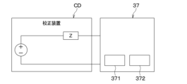
- the parasitic resistance value is obtained by connecting the precipitation amount detection unit 37 to a calibration device CD having a known impedance Z before connecting it to the lithium ion battery.
- the short circuit 371 is connected to the calibrating device CD, and the parasitic resistance value is obtained in this state. Then, the parasitic resistance value is stored in the storage unit 51 of the monitoring module 50 . Next, the short circuit 371 is connected to the battery module BM, and the lithium deposition amount is calculated in this state.
- the precipitation amount detection unit 37 configured in this manner can ensure robustness against parasitic impedance and temperature changes. This is very effective in accurately detecting the amount of deposited lithium.
- the short circuit 371 of the present embodiment includes a coil and has a large physique, so it is necessary to appropriately reduce the size in consideration of mountability. Downsizing can be achieved, for example, by improving the saturation magnetic flux density of the coil. Specific means for miniaturization include, for example, using a coil made of a material with a high magnetic flux density and improving the saturation magnetic flux density by providing a gap.
- the coating detection unit 38 detects the thickness of the coating formed at the interface between the negative electrode and the electrolyte during charging of the lithium ion battery.
- This coating is also called the SEI layer.
- SEI is an abbreviation for Solid Electrolyte Interphase.
- the thickness of the SEI layer has a correlation with current and voltage behavior when both ends of the lithium-ion battery are short-circuited with a short circuit 371.
- the film detection unit 38 estimates the thickness of the SEI layer from the current and voltage behavior when both ends of the lithium ion battery are short-circuited by the short circuit 371 .
- the coating detection unit 38 detects the correlation between the thickness of the SEI layer included in the signal waveform of at least one of the current and voltage flowing through the short-circuit 371. extract a certain component, and estimate the thickness of the SEI layer from the extracted component. It should be noted that when detecting the thickness of the SEI layer, it is desirable to correct the thickness using the battery temperature, as in the case of detecting the amount of deposited lithium.
- the amount of deposited lithium and the thickness of the SEI layer are physical quantities that have a higher correlation with battery capacity deterioration than battery voltage and current.
- the deposition amount detection unit 37 and the film detection unit 38 constitute a "deterioration detection unit” that detects a physical quantity that has a higher correlation with battery capacity deterioration than battery voltage and current.
- the amount of deposited lithium is one of the factors leading to abnormal heat generation in which the temperature of the battery continues to rise unintentionally.
- the precipitation amount detection unit 37 constitutes a "factor monitoring unit” that monitors factors leading to the abnormal heat generation phenomenon.
- the flexible substrate FPC is mounted with a battery state detection unit 39 that detects the battery state. For example, based on the sensor outputs of the temperature sensor 31, the current sensor 32, and the voltage sensor 33, the battery state detection unit 39 detects a battery state in which the battery temperature is excessive, a battery state in which the battery is overcharged, and a battery state in which the internal resistance is large. Detects changing battery status, etc.
- the monitoring module 50 is a satellite module attached directly to the battery module BM.
- the monitor module 50 is the device on the high voltage side of the BMU.
- the monitoring module 50 constitutes an "abnormality detection unit" that is electrically connected to the battery and detects an abnormality in the battery.
- the monitoring module 50 includes a storage unit 51, a wireless communication unit 52, an internal resistance detection unit 53, a monitoring IC 54, and the like.
- the storage unit 51 stores various types of information such as a unique ID set for each monitoring module 50, the monitoring result of the battery module BM, the aforementioned parasitic resistance value, and the like.
- the storage unit 51 is composed of a non-transitional substantive storage medium.
- the wireless communication unit 52 is a communication device for enabling two-way communication with the battery ECU 100.
- the monitoring module 50 receives various signals from the battery ECU 100 and transmits monitoring results of the monitoring module 50 and the like to the battery ECU 100 .
- the internal resistance detection section 53 is a device that detects the internal resistance of the battery based on various information output from the sensor section 30 . Also, a change in the internal resistance of the battery is one of the factors leading to abnormal heat generation. Therefore, the internal resistance detection section 53 constitutes a "factor monitoring section" that monitors factors leading to abnormal heat generation.
- the monitoring IC 54 is electrically connected to the battery to detect battery abnormalities.
- the monitoring IC 54 suppresses the occurrence of the abnormal heat phenomenon based on the results of monitoring factors that lead to the abnormal heat phenomenon, detects an abnormal state that occurs in the battery at the initial stage of the occurrence of the abnormal heat phenomenon, and monitors the abnormal state detection result.
- the monitoring IC 54 includes an ASIC circuit having an algorithm that performs at least part of the monitoring of factors leading to abnormal heat generation and the detection of an abnormal state that occurs in the battery at the initial stage of occurrence of the abnormal heat generation.
- the monitoring IC 54 is configured to have a diagnostic section 541, an SOH estimating section 542, and a monitoring control section 543 as functional sections for executing various controls.
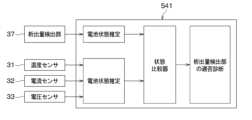
- Diagnosis section 541 compares a predetermined battery state estimated from the amount of deposited lithium with a battery state estimated from factors other than the amount of deposited lithium to diagnose suitability of deposition amount detection section 37 .
- the diagnostic unit 541 estimates the volumetric ratio SOH of the battery from the lithium deposition amount detected by the deposition amount detection unit 37, as shown in FIG. Moreover, the diagnosis unit 541 estimates the volumetric ratio SOH of the battery based on the sensor outputs of the temperature sensor 31 , the current sensor 32 , and the voltage sensor 33 .
- SOH is an abbreviation for State of Health.
- the diagnosis unit 541 compares the volume ratio SOH estimated from the amount of lithium deposition with the volume ratio SOH estimated from the temperature, current, and voltage of the battery using a state comparator, Diagnose suitability. For example, if the discrepancy between the volume ratio SOH estimated from the lithium deposition amount and the volume ratio SOH estimated from the temperature, current, and voltage of the battery is within a predetermined range, the diagnosis unit 541 determines that the deposition amount detection unit 37 is appropriate. Diagnose.
- the diagnosis unit 541 determines that the deposition amount detection unit 37 is diagnosed as unsuitable.
- the monitoring IC 54 prohibits the detection of the amount of lithium deposition and control processing using the amount of lithium deposition, or detects the failure of the deposition amount detection unit 37 via the wireless communication unit 52. to the battery ECU 100.
- the battery volume ratio SOH was exemplified as the battery state estimated by the diagnostic unit 541, but the diagnostic unit 541 may estimate a battery state other than the volume ratio.
- Japanese Patent Application Laid-Open No. 2014-102076 discloses a method for calculating the fully charged amount of the battery.
- the current value of the output current of the battery is time-integrated to calculate the amount of change in charge/discharge amount between the first point in time and the second point in time.
- the OCV at the first time point and the second time point are measured, the SOC-OCV curve is used to calculate the remaining capacity SOC at the first time point and the second time point, and the deviation of the remaining capacity SOC at each time point is calculated.
- a change amount ⁇ SOC calculated as follows is calculated.
- the full charge amount of the battery is calculated by dividing the amount of change in charge/discharge amount by the amount of change ⁇ SOC in remaining capacity SOC. Further, the volume ratio SOH of the battery is obtained by dividing the full charge amount of the battery by the initial value of the full charge amount.
- the method of calculating the remaining capacity SOC and the volume ratio SOH described above does not calculate the charge/discharge amount of the battery unless there is a scene in which a certain amount of charge or discharge occurs. It cannot be calculated, lacks real-time performance, and has problems in practicality. There is also a problem that the calculation error of the volume ratio SOH increases with time due to the offset error of the current sensor 32 when calculating the charge/discharge amount.
- the SOH estimating unit 542 estimates the volumetric ratio SOH of the battery based on a physical quantity that has a higher correlation with the deterioration of the capacity of the battery than the voltage and current of the battery.
- the SOH estimator 542 constitutes a "volume ratio estimator”.
- the internal resistance of a battery has a strong correlation with physical quantities such as the amount of lithium deposition and the internal resistance of the battery. Also, the internal resistance of the battery is temperature dependent and affects the current and voltage of the battery.
- the SOH estimating unit 542 of the present embodiment estimates the rate SOH.
- the model for estimating the volume ratio SOH is, for example, a control map or a function that defines the relationship between the volume ratio SOH, the lithium deposition amount, the thickness of the SEI layer, the temperature of the battery, the current, and the voltage.
- the estimation model may be, for example, a model obtained by deep learning, reinforcement learning, or deep reinforcement learning using a neural network.
- the monitoring control unit 543 suppresses the occurrence of the abnormal heat phenomenon based on the monitoring results of the factors leading to the abnormal heat phenomenon, detects an abnormal state that occurs in the battery at the initial stage of occurrence of the abnormal heat phenomenon, and controls the abnormal state. Implement countermeasures against abnormal heat generation based on the detection results.
- the monitoring IC 54 controls a circuit for equalizing the voltages of the plurality of battery cells C, and the like.
- the battery ECU 100 is a main module in the BMU and controls charging and discharging of each battery module BM.
- the battery ECU 100 is a device on the low voltage side of the BMU.
- the battery ECU 100 is configured by a microcomputer including a processor, memory, I/O, wireless communication device 110, and the like.
- the battery ECU 100 is configured to be able to communicate with each monitoring module 50A, 50B, 50C via the wireless communication device 110 .
- the battery ECU 100 is connected to various ECUs via communication paths such as CAN. Examples of various ECUs include a heat management ECU for controlling a battery temperature control device, an ECU for an HMI device mounted on a vehicle, and the like.
- the battery ECU 100 can notify the outside of various battery states via an HMI device or the like.
- the battery pack 1 configured in this manner includes a chargeable/dischargeable battery such as a lithium ion battery.
- a chargeable/dischargeable battery such as a lithium ion battery.
- a specific member inside the battery generates heat for some reason, and that heat generation further causes other members to heat up.
- the thermal reliability of the battery is significantly lowered, which is not preferable. Therefore, it is important for lithium ion batteries and the like to ensure thermal reliability by detecting the presence or absence of abnormal heat generation in the battery.
- FIG. 11 shows an example of the results of verification by the inventors of the output changes of various sensors before and after an abnormal heat generation phenomenon.
- the battery volume starts to change due to an increase in the gas pressure inside the battery cell.
- the output of the strain sensor 34 tends to increase.
- the battery breaks and the gas inside the battery cell begins to leak.
- the output of the gas sensor 35 tends to increase.
- the gas pressure inside the battery decreases and the output of the strain sensor 34 tends to decrease.
- the battery monitoring device 20 executes control processing for preventing and early detection of abnormal phenomena.
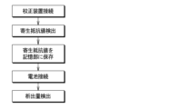
- An example of control processing executed by the battery monitoring device 20 will be described below with reference to FIG. 12 .
- the control process shown in FIG. 12 is executed by the battery monitoring device 20 periodically or irregularly, for example, while the vehicle is starting up and until a predetermined period of time has elapsed since the vehicle was stopped.
- Each processing shown in this flowchart is implemented by each functional unit of the battery monitoring device 20 . Further, each step for realizing this processing can also be grasped as each step for realizing the battery monitoring method.
- the battery monitoring device 20 reads various signals from the sensor section 30 and the like in step S100. Then, in step S105, the battery monitoring device 20 determines whether or not an abnormal heat generation phenomenon has occurred. As described above, in the initial stage of abnormal heat generation, the battery temperature, the pack internal pressure, and the output of the gas sensor 35 rapidly increase, and the battery voltage rapidly drops. Taking this into consideration, the battery monitoring device 20 determines whether or not an abnormal heat generation phenomenon has occurred based on at least some of the sensor outputs of the temperature sensor 31, the voltage sensor 33, the gas sensor 35, and the pack internal pressure sensor 36.
- the battery monitoring device 20 proceeds to step S110 and takes measures against the abnormal heat generation phenomenon.
- This countermeasure includes external notification processing for informing the outside of the occurrence of the abnormal heat phenomenon, and battery protection processing by at least one of battery cooling and charge/discharge control.
- a signal indicating the occurrence of an abnormal heat generation phenomenon is output to the battery ECU 100, and a device having a notification function such as an HMI device is operated via the battery ECU 100 to inform the user or battery manager of the abnormal heat generation phenomenon. to notify the occurrence of
- a signal instructing battery cooling is output to the battery ECU 100, and the temperature control device for the battery is operated via the battery ECU 100 to cool the battery.
- Such battery cooling makes it possible to delay the progress of abnormal heat generation in the battery.
- a signal instructing restriction of charging and discharging of the battery is output to the battery ECU 100 to restrict battery operation, thereby suppressing self-heating of the battery.
- charge/discharge control also makes it possible to delay the progress of abnormal heat generation in the battery.
- the battery protection process constitutes an extension process that extends the life of the battery.
- the battery monitoring device 20 detects an abnormality in a plurality of battery cells C based on at least one of the monitoring result of each of the plurality of battery cells C and the detection result of an abnormal state of the battery. are identified as abnormal cells. According to this, it is possible to limit the use of abnormal cells and delay the progress of abnormal heat generation.
- countermeasures against abnormal heat generation are not limited to the above processes, and may be realized by processes other than those described above.
- Countermeasures against the abnormal heating phenomenon may be, for example, turning on a warning light or sounding an alarm.
- step S115 the processing after step S115 is processing for preventing occurrence of an abnormal heat generation phenomenon.
- step S115 the battery monitoring device 20 determines whether overcharging of the battery has been detected. Overcharging of the battery can be detected by monitoring the sensor output of the voltage sensor 33, for example. When overcharging of the battery is detected, the battery monitoring device 20 executes charging suppression processing in step S120, and returns to step S115. In this charging suppression process, charging of the battery is suppressed or the battery is discharged.
- the battery monitoring device 20 determines in step S125 whether an excessive temperature rise of the battery has been detected. Excessive temperature rise of the battery can be detected by monitoring the sensor output of the temperature sensor 31, for example. When the excessive temperature rise of the battery is detected, the battery monitoring device 20 performs output limitation and cooling control in step S130, and returns to step S115. In the output limitation, for example, battery charge/discharge is suppressed. In cooling control, for example, the battery is cooled by a battery temperature control device.
- the battery monitoring device 20 determines in step S135 whether lithium deposition has been newly detected.
- Lithium deposition can be detected, for example, by monitoring the amount of increase in the amount of lithium deposition detected by the deposition amount detection unit 37 .
- the battery monitoring device 20 When lithium deposition is newly detected, the battery monitoring device 20 performs charging, regeneration control, and heating control in step S140, and returns to step S115.
- charging/regenerative control for example, battery charging is suppressed.
- heating control for example, the battery is warmed by a battery temperature control device.
- the battery monitoring device 20 determines in step S145 whether or not a change in internal resistance of the battery has been detected.
- the internal resistance of the battery can be detected, for example, by monitoring the increase in internal resistance detected by the internal resistance detector 53 .
- the battery monitoring device 20 When a change in the internal resistance of the battery is detected, the battery monitoring device 20 performs battery output limitation, temperature control, and notification of the degree of deterioration in step S150, and returns to step S115.
- output control for example, battery discharge is suppressed.
- temperature regulation control for example, the battery temperature is adjusted by a temperature regulation device so that the battery temperature is maintained within an appropriate range.
- notification of the degree of deterioration the degree of deterioration of the battery is determined from the internal resistance of the battery, and the determination result of the degree of deterioration or the time to replace the battery estimated from the determination result is notified to the outside.
- Each process performed when a change in internal resistance is detected constitutes an extension process for extending the life of the battery.
- the battery monitoring device 20 determines in step S155 whether or not deformation of the battery has been detected. Deformation of the battery can be detected by monitoring the sensor output amount of the strain sensor 34 .
- the battery monitoring device 20 limits the output of the battery in step S160, and returns to step S115. In output control, for example, battery charge/discharge is suppressed.
- the battery monitoring device 20 terminates the control process shown in FIG. 12 .
- the battery monitoring device 20 of the present embodiment can obtain the remaining capacity SOC and volume ratio SOH in real time. Taking this into consideration, it is desirable to use the battery module BM and the battery monitoring device 20 as a battery unit UT, and distribute the market in units of the battery unit UT. Then, it is desirable to manage the battery module BM by, for example, a battery management system BMS shown in FIG.
- the battery management system BMS includes a battery monitoring device 20 and a battery management device 60 attached to the battery module BM.
- Battery management device 60 includes performance determination unit 61 , value setting unit 62 , and performance notification unit 63 .
- the performance determination unit 61 determines whether secondary use of the battery is possible based on the volumetric ratio SOH estimated by the SOH estimation unit 542 of the battery monitoring device 20 . For example, if the floor area ratio SOH estimated by the SOH estimating unit 542 is equal to or greater than a predetermined value, the performance determination unit 61 determines that secondary use is permitted, and if it is less than the predetermined value, secondary use is not permitted. Note that the performance determination unit 61 may determine whether or not the secondary use of the battery is possible based on the battery state other than the volume ratio SOH.
- the value setting unit 62 determines whether there is an abnormality in the battery based on the volumetric ratio SOH estimated by the SOH estimation unit 542 of the battery monitoring device 20, and sets the residual value of the battery when there is an abnormality in the battery. .
- the value setting unit 62 for example, underestimates the remaining value of the battery as the volumetric ratio SOH decreases. Note that the value setting unit 62 may set the residual value of the battery based on the battery state other than the volumetric ratio SOH.
- the performance notification unit 63 determines whether the volume ratio SOH estimated by the SOH estimation unit 542 of the battery monitoring device 20 is within the allowable range of the volume ratio SOH indicated in the battery specification data, and notifies the result of this determination to an external device. output to
- the performance notification unit 63 acquires battery specification data provided by the battery manufacturer or the like and stores it in the memory. Then, for example, when the floor area ratio SOH estimated by the SOH estimating unit 542 is within the allowable range indicated by the specification data, the performance notification unit 63 notifies the battery distributor, the secondary user, etc. to that effect. . Further, for example, when the volume ratio SOH estimated by the SOH estimation unit 542 is out of the allowable range shown in the specification data, the performance notification unit 63 notifies the battery dealer that the secondary use of the battery is difficult. Notify secondary users, etc.
- the battery monitoring device 20 and the battery monitoring method monitor factors leading to abnormal heat generation, and prevent the occurrence of abnormal heat generation based on the monitoring results of the factors.
- the battery monitoring device 20 and the battery monitoring method detect an abnormal state occurring in the battery at an early stage of occurrence of the abnormal heat generation phenomenon, and take countermeasures against the abnormal heat generation phenomenon based on the detection result of the abnormal state. According to this, it is possible to prevent the occurrence of an abnormal heat generation phenomenon, and even if an abnormal heat generation phenomenon occurs, it is possible to implement effective countermeasures against heat, such as implementing countermeasures from the initial stage of occurrence.
- the battery monitoring device 20 has the following effects.
- the monitoring module 50 of the battery monitoring device 20 monitors factors leading to abnormal heat generation and detects an abnormal state of the battery in parallel. In other words, the monitoring module 50 detects an abnormal state of the battery regardless of the monitoring results of the factors leading to the abnormal heat phenomenon. According to this, an abnormal state can be detected earlier than, for example, when an abnormal state is detected after monitoring factors leading to an abnormal heat generation phenomenon, so countermeasures against the abnormal heat generation phenomenon can be implemented early. can.
- Countermeasures against abnormal heat generation include external notification processing to inform the outside of the occurrence of abnormal heat generation, or battery protection processing by at least one of battery temperature adjustment control and charge/discharge control.
- external notification processing is included in the countermeasures against the abnormal heat phenomenon, in addition to countermeasures that the battery monitoring device 20 itself can take, countermeasures by external devices of the battery monitoring device 20 and countermeasures in cooperation with external devices can be easily implemented. . Also, if battery protection processing is included in measures against abnormal heat generation, the battery can be appropriately protected.
- the monitoring module 50 performs an extension process for extending the life of the battery according to the monitoring result of the factor of the abnormal heat phenomenon. In this way, if the battery life extension process is executed according to the monitoring result of the factor leading to the abnormal heat generation phenomenon, the battery life can be appropriately extended.
- Factors leading to abnormal heat generation include at least one of lithium deposition inside the battery and internal resistance of the battery. Deposition of lithium inside a lithium-ion battery and an increase in internal resistance are factors that cause an abnormal heat generation phenomenon in the battery. Therefore, by monitoring the deposition of lithium and the internal resistance, it becomes easier to prevent the occurrence of abnormal heat generation in the battery.
- the monitoring module 50 identifies an abnormal cell in the plurality of battery cells C as an abnormal cell based on at least one of the monitoring results of each of the plurality of battery cells C and the detection result of the abnormal state of the plurality of battery cells C. Identify. In this way, with a configuration that can identify an abnormal cell from among a plurality of battery cells C, for example, the use of abnormal cells is restricted to prevent the occurrence of an abnormal heat generation phenomenon, or to prevent the abnormal heat generation phenomenon from progressing. can be delayed.
- the monitoring module 50 is configured to be able to detect at least one of abnormal battery conditions, such as abnormal internal pressure of the sealed container 11, abnormal battery temperature, abnormal battery voltage, and abnormal gas in the sealed container 11.
- abnormal battery conditions such as abnormal internal pressure of the sealed container 11, abnormal battery temperature, abnormal battery voltage, and abnormal gas in the sealed container 11.
- the internal pressure of the sealed container 11 containing the battery, the temperature of the battery, the voltage of the battery, and the gas state in the sealed container 11 become abnormal. Therefore, if the monitoring module 50 is configured to be able to detect at least one of abnormal internal pressure of the sealed container 11, abnormal battery temperature, abnormal battery voltage, and abnormal gas in the sealed container 11, the abnormal heat generation phenomenon can be detected. Easier to detect in the early stages of development.
- the battery monitoring device 20 includes an ASIC circuit having an algorithm that performs at least part of monitoring of factors leading to abnormal heat generation and detection of an abnormal state of the battery. According to this, it is possible to monitor factors leading to abnormal heat generation and detect abnormal conditions with a simple configuration.
- the monitoring module 50 can determine the degree of deterioration of the battery based on the results of monitoring factors leading to abnormal heat generation, and notify the outside of the determination result of the degree of deterioration or the battery replacement time estimated from the determination result. is configured to In this way, if the degree of deterioration of the battery is determined from the results of monitoring the factors leading to the abnormal heat generation phenomenon, a dedicated device for determining the degree of deterioration of the battery is not required. This contributes to simplification of the battery monitoring device 20 .
- connection member 21 that connects the battery and the monitoring module 50 includes a flexible substrate FPC on which a part of the sensor section 30 is mounted.
- the deposition amount detection unit 37 of the battery monitoring device 20 calculates an estimated value of the deposition amount of lithium based on changes in at least one of the current and voltage when both ends of the lithium ion battery are short-circuited by the short circuit 371 . Then, the deposition amount detection unit 37 corrects the estimated value of the deposition amount of lithium with the battery temperature. According to this, the influence of the battery temperature included in the estimated value of the lithium deposition amount can be reduced, and the detection accuracy of the lithium deposition amount can be improved, so the reliability of the deposition amount detection unit 37 can be ensured. .
- the deposition amount detection unit 37 corrects the estimated value of the deposition amount of lithium with the parasitic resistance value stored in the storage unit 51 . According to this, the influence of the parasitic impedance included in the estimated value of the deposited lithium amount can be reduced, and the detection accuracy of the deposited lithium amount can be improved, so the reliability of the deposited amount detection unit 37 can be ensured. .
- the deposition amount detection unit 37 corrects the parasitic resistance value stored in the storage unit 51 according to the battery temperature, and calculates the lithium deposition amount using the corrected parasitic resistance value. According to this, the influence of the battery temperature and the parasitic impedance included in the estimated value of the lithium deposition amount can be reduced, and the detection accuracy of the lithium deposition amount can be improved.
- the parasitic resistance value is obtained by connecting the short circuit 371 to a calibration device CD having a known impedance Z before connecting it to the lithium ion battery. According to this, the parasitic resistance value of the precipitation amount detection unit 37 can be obtained with high accuracy. This greatly contributes to improving the detection accuracy of the amount of deposited lithium.
- the battery monitoring device 20 compares a predetermined battery state estimated from the amount of lithium deposition with a predetermined battery state estimated from factors other than the amount of lithium deposition, and determines whether the deposition amount detection unit 37 is appropriate or not.
- a diagnosis unit 541 for diagnosing is provided. According to this, since the reliability of the precipitation amount detection unit 37 can be diagnosed by the diagnosis unit 541, the reliability of the precipitation amount detection unit 37 can be ensured.
- the battery monitoring device 20 detects a physical quantity that has a higher correlation with battery capacity deterioration than the battery voltage and current, and estimates the volumetric ratio SOH of the battery based on the physical quantity. In this way, if the volume ratio SOH is estimated by a physical quantity that is highly correlated with battery capacity deterioration, there is a need to avoid the influence of errors compared to the case where the volume ratio SOH is obtained from the current and voltage of the battery. Since it is small, the volume ratio SOH can be estimated in a short time. Therefore, according to the battery monitoring device 20 of the present invention, it is possible to grasp the battery state in a practical manner.
- the amount of lithium deposition and the thickness of the SEI layer are physical quantities that directly affect the capacity deterioration of the battery. Therefore, by detecting the amount of deposited lithium and the thickness of the SEI layer and obtaining the volume ratio SOH based on the amount of deposited lithium and the thickness of the SEI layer, it is possible to ensure real-time performance.
- the degree of cracking of the positive electrode active material inside the battery is a physical quantity that directly affects the capacity deterioration of the battery. Therefore, the detection accuracy of the volume ratio SOH can be improved by adopting a configuration in which the volume ratio SOH is determined based on not only the amount of lithium deposition and the thickness of the SEI layer but also the degree of cracking of the positive electrode active material.
- the degree of cracking of the positive electrode active material can be estimated based on the behavior of current and voltage when both ends of the lithium ion battery are short-circuited, or the sensor output of a strain sensor or an ultrasonic sensor.
- the amount of deposited lithium and the thickness of the SEI layer in a lithium ion battery are correlated with the behavior of current and voltage when both ends of the lithium ion battery are short-circuited. Taking this into account, the battery monitoring device 20 determines at least the amount of deposited lithium and the thickness of the SEI layer based on changes in at least one of the current and voltage when both ends of the lithium ion battery are short-circuited by the short circuit 371. Calculate one.
- the battery monitoring device 20 corrects at least one of the amount of lithium deposition and the thickness of the SEI layer with the battery temperature. According to this, the influence of the battery temperature included in the estimated value of the lithium deposition amount and the thickness of the SEI layer can be reduced, and the detection accuracy of the lithium deposition amount and the thickness of the SEI layer can be improved.
- the battery management system BMS determines whether secondary use of the battery is possible based on the volume ratio SOH estimated by the SOH estimation unit 542 of the battery monitoring device 20 . This makes it easier to determine which of reuse, rebuild, and recycle should be selected when the battery is to be used for secondary purposes. This greatly contributes to the construction of a battery ecosystem suitable for a recycling-oriented society.
- the battery management system BMS determines whether there is an abnormality in the battery based on the volumetric ratio SOH estimated by the SOH estimation unit 542 of the battery monitoring device 20. set. This also makes it easier to determine which of reuse, rebuild, and recycle should be selected when the battery is to be used for secondary purposes, contributing to the construction of a battery ecosystem adapted to a recycling-oriented society.
- the battery management system BMS determines whether the volumetric ratio SOH estimated by the SOH estimating unit 542 of the battery monitoring device 20 is within the allowable range of the volumetric ratio SOH indicated in the battery specification data. Output the result externally. This also makes it easier to decide which of reuse, rebuild, and recycle should be selected when the battery is to be used for secondary purposes.
- the battery monitoring device 20 of the present invention is essential for estimating the volume ratio SOH of the battery by the battery monitoring device 20, but is not essential for measures against abnormal heat generation of the battery and detection of the lithium deposition amount of the lithium ion battery.
- the amount of lithium deposited and the internal resistance of the battery are monitored as factors leading to the abnormal heat generation phenomenon, but physical quantities other than these are monitored as factors leading to the abnormal heat generation phenomenon. good too.
- a plurality of processes are illustrated as countermeasures against the abnormal heating phenomenon, but the battery monitoring device 20 may carry out some of the processes. Further, measures other than those described above may be used as countermeasures against the abnormal heat generation phenomenon.
- abnormal conditions occurring in the battery at the initial stage of occurrence of abnormal heat generation include abnormal internal pressure of the sealed container 11, abnormal battery temperature, abnormal battery voltage, and abnormal gas in the sealed container 11. It is not limited to this. A battery state other than these may be detected as an abnormal state occurring in the initial stage of occurrence of an abnormal heat generation phenomenon.
- the battery monitoring device 20 described above includes a flexible substrate FPC and an ASIC circuit, it is not limited to this.
- the flexible printed circuit board FPC and ASIC circuit are not essential components in the battery monitoring device 20 .
- the battery monitoring device 20 is preferably adapted to correct the estimated lithium deposition amount by the battery temperature or the parasitic resistance value, but it does not have to be.
- the battery monitoring device 20 compares the predetermined battery state estimated from the lithium deposition amount with the predetermined battery state estimated from other factors, and determines whether the deposition amount detection unit 37 is appropriate. It is desirable to be able to diagnose, but it does not have to be.
- the volume ratio SOH is estimated based on the amount of lithium deposited and the thickness of the SEI layer of the battery, but the volume ratio SOH is estimated based on other physical quantities.
- the battery monitoring device 20 may, for example, detect a deterioration state including cracks in the positive electrode of the battery, and calculate the volumetric ratio SOH based on the deterioration state.
- the battery monitoring device 20 be able to form a battery management system BMS that manages the battery modules BM together with the battery management device 60, but it does not have to be.
- the monitoring target of the battery monitoring device 20 is not limited to the vehicle-mounted battery mounted on the vehicle.
- the battery monitoring device 20 can also be used, for example, as a device for monitoring stationary storage batteries and portable storage batteries.
- the battery monitoring device 20 basically monitors lithium-ion batteries, but it is not limited to this, and if there is a battery that can cause the same problem as a lithium-ion battery, the battery can also be monitored. It should be noted that the battery to be monitored by the battery monitoring device 20 does not have to be formed by modularizing a plurality of battery cells C. FIG.
- the battery monitoring device 20 may be connected to the battery ECU 100 not wirelessly, but wiredly.
- the battery monitoring device 20 is not limited to one that completely matches the one described above, and may be partially different from the one described above.
- the controller and techniques of the present disclosure may be implemented on a dedicated computer provided by configuring a processor and memory programmed to perform one or more functions embodied by the computer program. good too.
- the controller and techniques of the present disclosure may be implemented in a dedicated computer provided by configuring the processor with one or more dedicated hardware logic circuits.
- the control unit and method of the present disclosure is a combination of a processor and memory programmed to perform one or more functions and a processor configured by one or more hardware logic circuits. It may be implemented on one or more dedicated computers.
- the computer program may also be stored as computer-executable instructions on a computer-readable non-transitional tangible recording medium.
Landscapes
- Engineering & Computer Science (AREA)
- General Physics & Mathematics (AREA)
- Physics & Mathematics (AREA)
- Chemical & Material Sciences (AREA)
- Manufacturing & Machinery (AREA)
- Chemical Kinetics & Catalysis (AREA)
- Electrochemistry (AREA)
- General Chemical & Material Sciences (AREA)
- Power Engineering (AREA)
- Microelectronics & Electronic Packaging (AREA)
- Materials Engineering (AREA)
- Secondary Cells (AREA)
- Tests Of Electric Status Of Batteries (AREA)
- Charge And Discharge Circuits For Batteries Or The Like (AREA)
Priority Applications (4)
| Application Number | Priority Date | Filing Date | Title |
|---|---|---|---|
| EP22910988.9A EP4455699B1 (en) | 2021-12-24 | 2022-12-12 | Battery monitoring device and battery management system |
| KR1020247024043A KR20240125630A (ko) | 2021-12-24 | 2022-12-12 | 전지 감시 장치, 전지 관리 시스템 |
| CN202280085077.6A CN118475845A (zh) | 2021-12-24 | 2022-12-12 | 电池监视装置、电池管理系统 |
| US18/750,771 US20240345173A1 (en) | 2021-12-24 | 2024-06-21 | Battery monitoring device, and battery management system |
Applications Claiming Priority (2)
| Application Number | Priority Date | Filing Date | Title |
|---|---|---|---|
| JP2021-211049 | 2021-12-24 | ||
| JP2021211049A JP7632268B2 (ja) | 2021-12-24 | 2021-12-24 | 電池監視装置、電池管理システム |
Related Child Applications (1)
| Application Number | Title | Priority Date | Filing Date |
|---|---|---|---|
| US18/750,771 Continuation US20240345173A1 (en) | 2021-12-24 | 2024-06-21 | Battery monitoring device, and battery management system |
Publications (1)
| Publication Number | Publication Date |
|---|---|
| WO2023120280A1 true WO2023120280A1 (ja) | 2023-06-29 |
Family
ID=86902392
Family Applications (1)
| Application Number | Title | Priority Date | Filing Date |
|---|---|---|---|
| PCT/JP2022/045715 Ceased WO2023120280A1 (ja) | 2021-12-24 | 2022-12-12 | 電池監視装置、電池管理システム |
Country Status (6)
| Country | Link |
|---|---|
| US (1) | US20240345173A1 (https=) |
| EP (1) | EP4455699B1 (https=) |
| JP (1) | JP7632268B2 (https=) |
| KR (1) | KR20240125630A (https=) |
| CN (1) | CN118475845A (https=) |
| WO (1) | WO2023120280A1 (https=) |
Families Citing this family (1)
| Publication number | Priority date | Publication date | Assignee | Title |
|---|---|---|---|---|
| JP7764810B2 (ja) * | 2022-06-29 | 2025-11-06 | 株式会社デンソー | 充電システム、充電器 |
Citations (11)
| Publication number | Priority date | Publication date | Assignee | Title |
|---|---|---|---|---|
| JP2010086901A (ja) * | 2008-10-02 | 2010-04-15 | Nissan Motor Co Ltd | リチウム二次電池の劣化診断装置および劣化診断方法 |
| WO2011125213A1 (ja) * | 2010-04-09 | 2011-10-13 | トヨタ自動車株式会社 | 二次電池の劣化判定装置および劣化判定方法 |
| JP2011220917A (ja) * | 2010-04-13 | 2011-11-04 | Toyota Motor Corp | リチウムイオン二次電池の劣化判定装置および劣化判定方法 |
| WO2012046266A1 (ja) * | 2010-10-05 | 2012-04-12 | トヨタ自動車株式会社 | 蓄電素子の状態推定方法および状態推定装置 |
| WO2012131864A1 (ja) * | 2011-03-28 | 2012-10-04 | トヨタ自動車株式会社 | 電動車両およびその制御方法 |
| JP2014102076A (ja) | 2012-11-16 | 2014-06-05 | Denso Corp | 電池システム |
| JP2017091666A (ja) * | 2015-11-04 | 2017-05-25 | トヨタ自動車株式会社 | リチウム析出量推定方法 |
| JP2018073777A (ja) * | 2016-11-04 | 2018-05-10 | トヨタ自動車株式会社 | リチウムイオン二次電池の制御システム |
| JP2020085653A (ja) * | 2018-11-26 | 2020-06-04 | トヨタ自動車株式会社 | 電池情報処理システム |
| CN112782582A (zh) * | 2021-01-29 | 2021-05-11 | 远景动力技术(江苏)有限公司 | 一种锂离子电池负极析锂的检测方法 |
| JP2021118576A (ja) * | 2020-01-23 | 2021-08-10 | トヨタ自動車株式会社 | 車両用制御装置、方法、プログラム、及び車両 |
Family Cites Families (3)
| Publication number | Priority date | Publication date | Assignee | Title |
|---|---|---|---|---|
| WO2013128676A1 (ja) * | 2012-02-29 | 2013-09-06 | 新神戸電機株式会社 | リチウムイオン電池 |
| JP5971477B2 (ja) * | 2012-12-25 | 2016-08-17 | トヨタ自動車株式会社 | 二次電池の状態推定装置 |
| JP6284824B2 (ja) * | 2014-05-14 | 2018-02-28 | 日立オートモティブシステムズ株式会社 | 二次電池監視装置、二次電池劣化予測装置、および、二次電池の電池容量の予測方法 |
-
2021
- 2021-12-24 JP JP2021211049A patent/JP7632268B2/ja active Active
-
2022
- 2022-12-12 EP EP22910988.9A patent/EP4455699B1/en active Active
- 2022-12-12 WO PCT/JP2022/045715 patent/WO2023120280A1/ja not_active Ceased
- 2022-12-12 KR KR1020247024043A patent/KR20240125630A/ko active Pending
- 2022-12-12 CN CN202280085077.6A patent/CN118475845A/zh active Pending
-
2024
- 2024-06-21 US US18/750,771 patent/US20240345173A1/en active Pending
Patent Citations (11)
| Publication number | Priority date | Publication date | Assignee | Title |
|---|---|---|---|---|
| JP2010086901A (ja) * | 2008-10-02 | 2010-04-15 | Nissan Motor Co Ltd | リチウム二次電池の劣化診断装置および劣化診断方法 |
| WO2011125213A1 (ja) * | 2010-04-09 | 2011-10-13 | トヨタ自動車株式会社 | 二次電池の劣化判定装置および劣化判定方法 |
| JP2011220917A (ja) * | 2010-04-13 | 2011-11-04 | Toyota Motor Corp | リチウムイオン二次電池の劣化判定装置および劣化判定方法 |
| WO2012046266A1 (ja) * | 2010-10-05 | 2012-04-12 | トヨタ自動車株式会社 | 蓄電素子の状態推定方法および状態推定装置 |
| WO2012131864A1 (ja) * | 2011-03-28 | 2012-10-04 | トヨタ自動車株式会社 | 電動車両およびその制御方法 |
| JP2014102076A (ja) | 2012-11-16 | 2014-06-05 | Denso Corp | 電池システム |
| JP2017091666A (ja) * | 2015-11-04 | 2017-05-25 | トヨタ自動車株式会社 | リチウム析出量推定方法 |
| JP2018073777A (ja) * | 2016-11-04 | 2018-05-10 | トヨタ自動車株式会社 | リチウムイオン二次電池の制御システム |
| JP2020085653A (ja) * | 2018-11-26 | 2020-06-04 | トヨタ自動車株式会社 | 電池情報処理システム |
| JP2021118576A (ja) * | 2020-01-23 | 2021-08-10 | トヨタ自動車株式会社 | 車両用制御装置、方法、プログラム、及び車両 |
| CN112782582A (zh) * | 2021-01-29 | 2021-05-11 | 远景动力技术(江苏)有限公司 | 一种锂离子电池负极析锂的检测方法 |
Non-Patent Citations (1)
| Title |
|---|
| See also references of EP4455699A4 |
Also Published As
| Publication number | Publication date |
|---|---|
| CN118475845A (zh) | 2024-08-09 |
| JP2023095261A (ja) | 2023-07-06 |
| US20240345173A1 (en) | 2024-10-17 |
| EP4455699B1 (en) | 2026-02-11 |
| EP4455699A1 (en) | 2024-10-30 |
| EP4455699A4 (en) | 2025-04-23 |
| JP7632268B2 (ja) | 2025-02-19 |
| KR20240125630A (ko) | 2024-08-19 |
Similar Documents
| Publication | Publication Date | Title |
|---|---|---|
| US12442862B2 (en) | Device detecting abnormality of secondary battery, abnormality detection method, and program | |
| JP7640541B2 (ja) | 急速充電方法 | |
| US8947023B2 (en) | Battery control device and motor drive system | |
| JP7715087B2 (ja) | 電池監視装置 | |
| JP7683553B2 (ja) | 電池監視装置、電池輸送機器、電池監視方法 | |
| JP7639782B2 (ja) | 電池評価システム、電池評価方法 | |
| US9688159B2 (en) | Methods, apparatus, and systems for preventing over-temperature battery operation | |
| CN107923942A (zh) | 用于监测电池组中的多个电池单体的状态的方法 | |
| JP2012198175A (ja) | バッテリ状態監視装置 | |
| US20240347795A1 (en) | Battery monitoring device, battery transport apparatus, and battery monitoring method | |
| CN113016099B (zh) | 电池控制装置 | |
| US20240345173A1 (en) | Battery monitoring device, and battery management system | |
| JP7078293B2 (ja) | 電流センサ診断装置及び方法 | |
| US20250123335A1 (en) | Charging system and charger | |
| JP7852771B2 (ja) | 電池監視装置 | |
| CN118435072A (zh) | 电池监视装置、电池运输设备、电池监视方法 | |
| CN120457353A (zh) | 用于诊断电池的装置及方法 |
Legal Events
| Date | Code | Title | Description |
|---|---|---|---|
| 121 | Ep: the epo has been informed by wipo that ep was designated in this application |
Ref document number: 22910988 Country of ref document: EP Kind code of ref document: A1 |
|
| WWE | Wipo information: entry into national phase |
Ref document number: 202280085077.6 Country of ref document: CN |
|
| ENP | Entry into the national phase |
Ref document number: 20247024043 Country of ref document: KR Kind code of ref document: A |
|
| WWE | Wipo information: entry into national phase |
Ref document number: 202417055735 Country of ref document: IN |
|
| NENP | Non-entry into the national phase |
Ref country code: DE |
|
| ENP | Entry into the national phase |
Ref document number: 2022910988 Country of ref document: EP Effective date: 20240724 |
|
| WWG | Wipo information: grant in national office |
Ref document number: 2022910988 Country of ref document: EP |