WO2023120255A1 - オーバーシース及び内視鏡用処置具装置並びに内視鏡用器具 - Google Patents
オーバーシース及び内視鏡用処置具装置並びに内視鏡用器具 Download PDFInfo
- Publication number
- WO2023120255A1 WO2023120255A1 PCT/JP2022/045538 JP2022045538W WO2023120255A1 WO 2023120255 A1 WO2023120255 A1 WO 2023120255A1 JP 2022045538 W JP2022045538 W JP 2022045538W WO 2023120255 A1 WO2023120255 A1 WO 2023120255A1
- Authority
- WO
- WIPO (PCT)
- Prior art keywords
- treatment instrument
- forceps
- oversheath
- endoscope
- endoscopic
- Prior art date
- Legal status (The legal status is an assumption and is not a legal conclusion. Google has not performed a legal analysis and makes no representation as to the accuracy of the status listed.)
- Ceased
Links
Images


Classifications
-
- A—HUMAN NECESSITIES
- A61—MEDICAL OR VETERINARY SCIENCE; HYGIENE
- A61B—DIAGNOSIS; SURGERY; IDENTIFICATION
- A61B17/00—Surgical instruments, devices or methods
- A61B17/28—Surgical forceps
- A61B17/29—Forceps for use in minimally invasive surgery
- A61B17/2909—Handles
-
- A—HUMAN NECESSITIES
- A61—MEDICAL OR VETERINARY SCIENCE; HYGIENE
- A61B—DIAGNOSIS; SURGERY; IDENTIFICATION
- A61B1/00—Instruments for performing medical examinations of the interior of cavities or tubes of the body by visual or photographical inspection, e.g. endoscopes; Illuminating arrangements therefor
- A61B1/012—Instruments for performing medical examinations of the interior of cavities or tubes of the body by visual or photographical inspection, e.g. endoscopes; Illuminating arrangements therefor characterised by internal passages or accessories therefor
- A61B1/018—Instruments for performing medical examinations of the interior of cavities or tubes of the body by visual or photographical inspection, e.g. endoscopes; Illuminating arrangements therefor characterised by internal passages or accessories therefor for receiving instruments
-
- A—HUMAN NECESSITIES
- A61—MEDICAL OR VETERINARY SCIENCE; HYGIENE
- A61B—DIAGNOSIS; SURGERY; IDENTIFICATION
- A61B1/00—Instruments for performing medical examinations of the interior of cavities or tubes of the body by visual or photographical inspection, e.g. endoscopes; Illuminating arrangements therefor
- A61B1/00131—Accessories for endoscopes
- A61B1/00133—Drive units for endoscopic tools inserted through or with the endoscope
-
- A—HUMAN NECESSITIES
- A61—MEDICAL OR VETERINARY SCIENCE; HYGIENE
- A61B—DIAGNOSIS; SURGERY; IDENTIFICATION
- A61B1/00—Instruments for performing medical examinations of the interior of cavities or tubes of the body by visual or photographical inspection, e.g. endoscopes; Illuminating arrangements therefor
- A61B1/00131—Accessories for endoscopes
- A61B1/00137—End pieces at either end of the endoscope, e.g. caps, seals or forceps plugs
-
- A—HUMAN NECESSITIES
- A61—MEDICAL OR VETERINARY SCIENCE; HYGIENE
- A61B—DIAGNOSIS; SURGERY; IDENTIFICATION
- A61B1/00—Instruments for performing medical examinations of the interior of cavities or tubes of the body by visual or photographical inspection, e.g. endoscopes; Illuminating arrangements therefor
- A61B1/00131—Accessories for endoscopes
- A61B1/0014—Fastening element for attaching accessories to the outside of an endoscope, e.g. clips, clamps or bands
-
- A—HUMAN NECESSITIES
- A61—MEDICAL OR VETERINARY SCIENCE; HYGIENE
- A61B—DIAGNOSIS; SURGERY; IDENTIFICATION
- A61B1/00—Instruments for performing medical examinations of the interior of cavities or tubes of the body by visual or photographical inspection, e.g. endoscopes; Illuminating arrangements therefor
- A61B1/00142—Instruments for performing medical examinations of the interior of cavities or tubes of the body by visual or photographical inspection, e.g. endoscopes; Illuminating arrangements therefor with means for preventing contamination, e.g. by using a sanitary sheath
-
- A—HUMAN NECESSITIES
- A61—MEDICAL OR VETERINARY SCIENCE; HYGIENE
- A61B—DIAGNOSIS; SURGERY; IDENTIFICATION
- A61B17/00—Surgical instruments, devices or methods
- A61B17/32—Surgical cutting instruments
- A61B17/3205—Excision instruments
- A61B17/32056—Surgical snare instruments
-
- A—HUMAN NECESSITIES
- A61—MEDICAL OR VETERINARY SCIENCE; HYGIENE
- A61B—DIAGNOSIS; SURGERY; IDENTIFICATION
- A61B10/00—Instruments for taking body samples for diagnostic purposes; Other methods or instruments for diagnosis, e.g. for vaccination diagnosis, sex determination or ovulation-period determination; Throat striking implements
- A61B10/02—Instruments for taking cell samples or for biopsy
- A61B10/06—Biopsy forceps, e.g. with cup-shaped jaws
-
- A—HUMAN NECESSITIES
- A61—MEDICAL OR VETERINARY SCIENCE; HYGIENE
- A61B—DIAGNOSIS; SURGERY; IDENTIFICATION
- A61B18/00—Surgical instruments, devices or methods for transferring non-mechanical forms of energy to or from the body
- A61B18/04—Surgical instruments, devices or methods for transferring non-mechanical forms of energy to or from the body by heating
- A61B18/12—Surgical instruments, devices or methods for transferring non-mechanical forms of energy to or from the body by heating by passing a current through the tissue to be heated, e.g. high-frequency current
- A61B18/14—Probes or electrodes therefor
- A61B18/1442—Probes having pivoting end effectors, e.g. forceps
- A61B18/1445—Probes having pivoting end effectors, e.g. forceps at the distal end of a shaft, e.g. forceps or scissors at the end of a rigid rod
-
- A—HUMAN NECESSITIES
- A61—MEDICAL OR VETERINARY SCIENCE; HYGIENE
- A61B—DIAGNOSIS; SURGERY; IDENTIFICATION
- A61B17/00—Surgical instruments, devices or methods
- A61B2017/00477—Coupling
Definitions
- the present invention relates to an oversheath, an endoscopic treatment instrument device, and an endoscopic instrument that are used by being inserted through a forceps channel of an endoscope.
- the insertion part of an endoscope is inserted into the subject's body to perform not only observation inside the body but also various treatments on the observation site.
- various treatment instruments such as forceps and incision tools are passed through a forceps channel in the insertion section through a forceps opening provided in the operation section of the endoscope and led out from the forceps outlet opening at the distal end of the insertion section.
- various treatments such as excision and sampling of tissue or the like at the observation site are performed.
- Patent Literature 1 describes an endoscopic treatment instrument device including an endoscopic treatment instrument having a flexible sheath and an attachment section for attaching the flexible sheath to an operation section of the endoscope. ing.
- a flexible sheath is inserted into the body cavity through the forceps channel of the endoscope.
- a treatment instrument for an endoscope includes a flexible sheath, a flexible operation wire, a treatment section provided at the distal end of the operation wire, and a hard pipe connected to the proximal end of the operation wire.
- the operation wire and rigid pipe are supported so as to be able to advance and retreat with respect to the flexible sheath.
- the treatment portion is a snare wire that contracts when housed inside the flexible sheath and expands when projected from the distal end of the flexible sheath.
- the operation of the endoscopic treatment instrument that can be performed by the doctor is limited to the forceps channel. It is only an operation to advance and retreat with respect to. That is, operations other than the operation of advancing and retracting the treatment instrument with respect to the forceps channel, for example, the operation of expanding or contracting the treatment section, and the operation of rotating the treatment instrument with respect to the forceps channel around the center axis, are performed by the caregiver.
- the doctor needs to cooperate with the operation, such as issuing instructions to the caregiver.
- the number of people who perform treatment cannot be reduced.
- the present invention enables a treatment instrument operation that can be performed by either a doctor operating an endoscope or a caregiver, easily and with a small number of people, and is used for a plurality of types of endoscopes.
- An object of the present invention is to provide an oversheath, an endoscopic treatment instrument device, and an endoscopic instrument that are compatible with a treatment instrument.
- An oversheath of the present invention is an oversheath through which a flexible sheath of an endoscopic treatment instrument is inserted and which is inserted into a forceps channel of an endoscope in cooperation with the endoscopic treatment instrument. It comprises a first tubular portion and a second tubular portion.
- the first tubular portion has an outer peripheral side sliding portion that slides on the inner peripheral surface of the forceps port, which is an introduction port to the forceps channel.
- the second tubular portion is provided at the proximal end portion of the first tubular portion and has an inner peripheral sliding portion that allows the endoscopic treatment instrument to advance and retreat with respect to the forceps channel.
- a detachable member is provided integrally with the outer sheath and engaged with the forceps plug attached to the forceps channel, and when the detachable member is engaged with the forceps plug, the outer sheath is attached to the endoscope via the detachable member.
- the detachable member preferably has a first engaging portion that engages with the forceps plug and a second engaging portion that engages with a portion of the endoscope. It is preferable that the attachment/detachment member is attached to the forceps plug in a direction perpendicular to the axial direction of the outer sheath, or inclined from the direction perpendicular to the axial direction.
- the endoscopic treatment instrument be capable of advancing and retreating and rotating with respect to the oversheath within the range in which the third tubular portion and the inner peripheral sliding portion slide.
- the fitting part fits with the flexible sheath of the endoscopic treatment instrument or the operation part connected to the flexible sheath.
- the third tubular portion preferably has a dimension in the axial direction longer than the range in which the endoscopic treatment instrument advances and retreats with respect to the forceps channel.
- the outer sheath preferably has a sealing member that fills the gap with the inner sheath at the proximal end of the second tubular portion. It is preferable that the first tubular portion has a double-tube structure that allows the length in the axial direction to be stretchable. The length of the first tubular portion is preferably shorter than the flexible sheath.
- the forceps channel has a first inner diameter portion located on the side of the forceps opening, and a second inner diameter portion located closer to the distal end of the endoscope than the first inner diameter portion and having an inner diameter smaller than that of the first inner diameter portion.
- the outer diameter of the first tubular portion is smaller than the first inner diameter and greater than the second inner diameter.
- the first resistance when advancing and retreating the first tubular portion with respect to the forceps channel is greater than the second resistance when advancing and retreating the endoscopic treatment instrument with respect to the second tubular portion.
- An endoscopic treatment instrument device of the present invention has a treatment instrument main body having a tubular flexible sheath, an operation wire, and an operation portion, and an insertion conduit through which the flexible sheath is inserted,
- An endoscopic treatment instrument device including an oversheath that is inserted into a forceps channel of an endoscope in cooperation with a treatment instrument main body, wherein the oversheath has a first tubular portion and a second tubular portion. It comprises an outer sheath integrally provided, an inner sheath integrally provided with a fitting portion, and a third tubular portion.
- the operating wire is inserted through the flexible sheath, and the operating section is provided at the proximal end of the flexible sheath.
- the oversheath has an insertion channel through which the flexible sheath is inserted, and is inserted into the forceps channel of the endoscope in cooperation with the treatment instrument main body.
- the first tubular portion has an outer peripheral side sliding portion that slides on the inner peripheral surface of the forceps port, which is an introduction port to the forceps channel.
- the second tubular portion is provided at the proximal end portion of the first tubular portion and has an inner peripheral sliding portion that allows the treatment instrument main body to advance and retreat with respect to the forceps channel.
- the fitting portion is fitted onto the treatment instrument main body.
- the third tubular portion slides on the inner sliding portion and covers at least a portion of the flexible sheath.
- a detachable member is provided integrally with the outer sheath and engaged with the forceps plug attached to the forceps channel, and when the detachable member is engaged with the forceps plug, the outer sheath is attached to the endoscope via the detachable member. preferably.
- the endoscopic instrument of the present invention comprises a detachable member, the detachable member having a first engaging portion that engages with the forceps plug and a second engaging portion that engages with a portion of the endoscope.
- the detachable member When the detachable member is engaged with the forceps plug, it is attached to the endoscope via the detachable member.
- the detachable member engages a forceps plug mounted in a forceps channel of the endoscope.
- the endoscopic instrument includes a treatment instrument operation section, and the detachable member is provided integrally with the treatment instrument operation section.
- the treatment instrument operation section operates the endoscope instrument.
- the part of the endoscope with which the second engaging portion engages is located on the root side of the forceps plug. It is preferable that the endoscope instrument is arranged at a position where the axial direction intersects the attachment/detachment direction of the attachment/detachment member.
- a part of the endoscope with which the second engaging part engages is a treatment instrument introduction part that constitutes an operation part of the endoscope, and the endoscopic instrument is arranged in a direction along the treatment instrument introduction part. preferably.
- a treatment instrument that can be performed by either a doctor operating an endoscope or a caregiver, with a small number of people, and to perform a plurality of types of endoscopy. It can correspond to a speculum treatment tool.
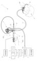
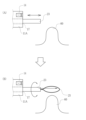
- FIG. 1 is a schematic diagram showing an endoscopy using an endoscope and an endoscopic treatment instrument device;
- FIG. 1 is a front view of an endoscope and a treatment instrument device for an endoscope;
- FIG. 4 is a cross-sectional view of the essential parts around the forceps plug in the endoscope;
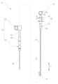
- 1 is a front view of an endoscopic treatment instrument device;
- FIG. 4 is an explanatory diagram of a state (A) in which the snare wire is spread and a state (B) in which the snare wire is contracted.
- FIG. 4 is a cross-sectional view of main parts of the oversheath;
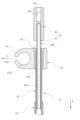
- FIG. 4 is an exploded perspective view showing the configuration of the oversheath;
- FIG. 4 is an exploded perspective view showing the configuration of the outer sheath;
- FIG. 4 is an explanatory view showing a contracted state (A) and an extended state (B) of the first tubular portion of the outer sheath;
- FIG. 4 is an explanatory diagram showing the relationship between the inner diameter of the forceps channel and the outer diameter of the outer sheath;
- FIG. 4 is a cross-sectional view of essential parts around an inner peripheral side sliding portion and a detachable member;
- FIG. 10 is a cross-sectional view of essential parts around the sealing member and the detachable member in a state where the third tubular portion of the inner sheath is inserted into the inner peripheral side sliding portion of the outer sheath;
- FIG. 4 is an explanatory view showing a contracted state (A) and an extended state (B) of the first tubular portion of the outer sheath;
- FIG. 4 is an explanatory diagram showing the relationship between the inner diameter of the forceps channel and the outer diameter of the
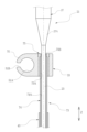
- FIG. 2 is a perspective view of the endoscopic treatment instrument with the inner sheath fitted thereto, and the outer sheath;
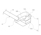
- Fig. 2 is a perspective view of a state in which the endoscopic treatment instrument is inserted into the oversheath; It is a perspective view of the detachable member periphery.
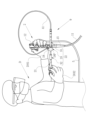
- Fig. 2 is a perspective view showing a state before the endoscope treatment instrument device is attached to the endoscope; It is explanatory drawing explaining the operation
- FIG. 4A is an explanatory view of treating a lesion using the endoscopic treatment device, showing a state in which the distal end of the flexible sheath is aligned with the position of the lesion (A), and a snare wire is protruded; It is explanatory drawing of a state (B).
- FIG. 10 is an explanatory view when treating a lesion using the endoscopic treatment device, and is an explanatory view of a state (A) in which the lesion is surrounded by a snare wire and a state (B) in which the lesion is excised. It is a front view of the treatment implement apparatus for endoscopes of 2nd Embodiment.
- FIG. 10 is an explanatory view when treating a lesion using the endoscopic treatment device, and is an explanatory view of a state (A) in which the lesion is surrounded by a snare wire and a state (B) in which the lesion is excised. It is a front view of the treatment implement
- FIG. 11 is a cross-sectional view of essential parts around an inner peripheral side sliding portion and a detachable member in a treatment instrument device for an endoscope according to a second embodiment;
- FIG. 11 is an explanatory diagram for explaining the operation when performing endoscopic examination and treatment in the first modified example;
- FIG. 11 is an explanatory diagram for explaining the operation when performing endoscopic examination and treatment in the second modified example;
- FIG. 11 is a plan view showing the arrangement of the outer sheath when the axial direction is not tilted (A) and when the axial direction is tilted in the third modified example;
- FIG. 11 is a plan view showing the arrangement of an outer sheath in a fourth modified example;
- FIG. 11 is a perspective view of an endoscope and an endoscopic treatment instrument device in a fifth modified example
- FIG. 14 is a perspective view of the endoscope and the endoscopic treatment instrument device in the fifth modified example, viewed from another direction
- FIG. 11 is a plan view of an endoscopic treatment instrument device in a fifth modified example
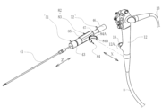
- FIG. 11 is a perspective view of an endoscope and an endoscope instrument according to a third embodiment
- FIG. 11 is a perspective view of an endoscopic instrument according to a third embodiment
- FIG. 11 is a perspective view of an endoscope and an endoscope instrument according to a fourth embodiment
- FIG. 12 is a perspective view of the distal end portion of the endoscope according to the fourth embodiment
- FIG. 12 is an exploded perspective view of the distal end portion of the endoscope according to the fourth embodiment
- FIG. 11 is an explanatory diagram for explaining the operation of the endoscopic instrument in the fourth embodiment;
- an endoscope system 1 of the present invention includes an endoscope 2, a processor device 3, a light source device 4, a display 5, a UI (User Interface) 6, a suction device 7, and a high frequency power supply 8. , and an endoscopic treatment instrument device 9 and the like.
- the endoscope 2 is, for example, an endoscope for upper gastrointestinal tracts such as esophagus and stomach, and has an insertion section 11 inserted into the upper gastrointestinal tract of a patient P, who is a subject, and a proximal end portion of the insertion section 11. and a universal cord 13 connected to the operation unit 12 .
- the universal cord 13 is connected to external devices such as the processor device 3 and the light source device 4 via the connector 13A.
- the processor device 3 is electrically connected with the display 5 and UI6.
- the UI 6 has a keyboard, a mouse, a touch pad, a microphone, etc., and receives input operations from a doctor D who is an operator.
- the insertion section 11 is composed of a distal end portion 11A, a bending portion 11B, and a flexible tube portion 11C in order from the distal end side to the proximal end side.
- an observation window and an illumination window are provided on the distal end surface of the distal end portion 11A.
- An image sensor 14 (see FIGS. 17 and 18) is arranged behind the observation window, and a light guide (optical fiber) cable (not shown) is arranged behind the illumination window.
- Signal lines and light guide cables of the image sensor 14 pass through the insertion portion 11, the operation portion 12, the universal cord 13, and the connector 13A, and are connected to the processor device 3 and the light source device 4, respectively.
- the processor device 3 performs image processing and the like on the endoscopic image captured by the image sensor 14 and causes the display 5 to display the image.
- the bending portion 11B is connected to the distal end portion 11A so as to be bendable.
- the mouthpiece MP for the endoscope When inserting the insertion portion 11 of the endoscope 2 from the mouth M of the patient P, the mouthpiece MP for the endoscope is attached to the mouth of the patient P.
- the endoscopic mouthpiece MP has a conduit (not shown) through which the insertion section 11 is inserted. A part of the endoscopic mouthpiece MP is inserted into the mouth M of the patient P, and the patient P holds the inserted part in his/her mouth so that the mouth of the patient P is fitted with the mouthpiece. This allows the insertion portion 11 to be introduced into the body through the duct.
- the operation portion 12 is integrally provided with a treatment instrument introduction portion 12A.
- the treatment instrument introduction portion 12A is a protrusion that protrudes from the outer peripheral surface of the operation portion 12 .
- the treatment instrument introduction portion 12A includes a base 16 (see FIG. 3). One end of the forceps channel 15 connects to the forceps outlet 17 and the other end connects to the base 16 .
- the mouthpiece 16 has a flange portion 16A on its outer peripheral surface.
- the inner peripheral surface 16B of the mouthpiece 16 is continuous with the inner peripheral surface of the forceps channel 15 .
- a forceps plug 18 is attached to the mouthpiece 16 .
- the flange portion 16A locks the forceps plug 18 .
- the forceps plug 18 is made of an elastically deformable resin, rubber member, or the like.
- the forceps plug 18 includes, for example, a cylindrical plug body 18A, a cap 18B fitted with the plug body 18A, and an attachment arm 18C. Also, the cap 18B has a knob portion 18D protruding from the outer diameter.
- the mounting arm 18C connects the plug body 18A and the cap 18B.
- a slit valve 18E having a slit through which the treatment instrument body 21 is inserted is provided inside the plug body 18A.
- the cap 18B is provided with a treatment instrument insertion hole 18F.
- the treatment instrument insertion hole 18F is positioned coaxially with the inner peripheral surface 16B of the base 16. As described above, since the inner peripheral surface 16B of the mouthpiece 16 is continuous with the inner peripheral surface of the forceps channel 15, the treatment instrument insertion hole 18F serves as an introduction port to the forceps channel 15.
- the treatment instrument insertion hole 18F in this embodiment corresponds to the "forceps port" in the scope of claims.
- the forceps channel 15 is also used as a path for sucking contents such as body fluids such as blood and body wastes from the forceps outlet 17 and as a path for feeding a washing liquid such as water.
- a suction channel 19 branched from the forceps channel 15 is arranged in the operating portion 12 .
- One end of the suction channel 19 is connected to the forceps channel 15 and the other end is connected to an operation button 12B provided on the operation section 12 .
- the operation button 12B has a suction valve (not shown) provided inside.
- the suction valve is connected to the suction channel 19 in the operation part 12, and is connected to an external suction device via a conduit (not shown) arranged in the operation part 12, the universal cord 13, the connector 13A, and the like. 7 is connected.
- the suction device 7 is, for example, a suction pump that creates a negative pressure.
- the high-frequency power supply 8 is connected to the endoscopic treatment device 9 via a cable (not shown), and applies a high-frequency current to a snare wire 25 (described later) of the endoscopic treatment device 9 . As a result, the lesion can be resected.
- the endoscopic treatment instrument device 9 includes a treatment instrument main body 21 and an oversheath 22 .
- the treatment instrument main body 21 corresponds to a "treatment instrument for an endoscope" or a “treatment instrument main body” in the claims.
- the treatment instrument main body 21 is, for example, a high-frequency snare that can excise a lesion by applying a high-frequency current.
- the oversheath 22 is inserted into the forceps channel 15 in cooperation with the treatment instrument main body 21 .
- the treatment instrument main body 21 includes a flexible sheath 23, an operation wire 24, a snare wire 25 as a treatment section, and an operation section 26.
- the flexible sheath 23 is a tubular sheath made of flexible material such as soft resin, and is inserted into the forceps channel 15 of the endoscope 2 together with the oversheath 22 .
- the operating wire 24 is provided integrally with the snare wire 25 and is passed through the flexible sheath 23 .
- the operating portion 26 includes an operating portion main body 27 and a slider 28 slidably supported by the operating portion main body 27 .
- the operation portion main body 27 is connected to the proximal end portion of the flexible sheath 23 .
- a tapered portion 27A is provided at the distal end portion of the operation portion main body 27, the outer diameter of which gradually decreases from the proximal end side to the distal end side.
- the operation portion main body 27 is provided with a finger hook portion 27B and a cylindrical portion 27C parallel to the insertion direction Z.
- the slider 28 is engaged with the cylindrical portion 27C and slides in the axial direction of the flexible sheath 23 along the cylindrical portion 27C.
- the operator's thumb is put on the finger hooking portion 27B, and the forefinger and middle finger of the same operator are put on the slider .
- a base end of the operation wire 24 is fixed to the slider 28 . Therefore, the operation wire 24 is pushed and pulled in the axial direction within the flexible sheath 23 as the slider 28 slides.
- the snare wire 25 expands into a loop shape when it protrudes from the distal end of the flexible sheath 23 in the insertion direction Z due to the push-pull operation of the operation wire 24 . This allows the snare wire 25 to surround the lesion.
- the snare wire 25 is contracted when it is housed inside the flexible sheath 23 by pushing and pulling the operating wire 24 as the slider 28 slides.
- the oversheath 22 includes an outer sheath 31, an inner sheath 32, and a detachable member 33.
- the outer sheath 31 is integrally provided with a first tubular portion 41, a second tubular portion 42, a connecting member 43, and a sealing member 44.
- the first tubular portion 41, the second tubular portion 42, the connecting member 43, and the sealing member 44 are made of a soft material such as soft resin.
- the length L11 of the first tubular portion 41 in the insertion direction Z is shorter than the length L12 of the flexible sheath 23 (see FIG. 4).
- the first tubular portion 41 is a flexible tubular sheath, through which the flexible sheath 23 of the treatment instrument main body 21 is inserted (see FIG. 14).
- the outer peripheral surface of the first tubular portion 41 is an outer peripheral sliding portion 41A.
- the outer peripheral side sliding portion 41A is formed to match the inner peripheral surface of the treatment instrument insertion hole 18F, and has an outer diameter slightly larger than the hole diameter of the treatment instrument insertion hole 18F.
- the slightly larger outer diameter referred to here means an outer diameter within a range in which the hole diameter of the treatment instrument insertion hole 18F expands due to elastic deformation. Thereby, the outer peripheral side sliding portion 41A slides on the inner peripheral surface of the treatment instrument insertion hole 18F.
- the first tubular portion 41 is composed of a small-diameter tube 45A, a large-diameter tube 45B, and a grip member 45C.
- the large-diameter tube 45B has a length in the axial direction, that is, the insertion direction Z, which is equal to or slightly shorter than that of the small-diameter tube 45A.
- the first tubular portion 41 has a double-tube structure whose length in the insertion direction Z can be expanded and contracted.
- the large-diameter tube 45B covers the small-diameter tube 45A and can move in the insertion direction Z relative to the small-diameter tube 45A.
- the grip member 45C has an outer diameter larger than that of the large-diameter tube 45B, and the large-diameter tube 45B is fixed to its inner peripheral surface. The grip member 45C moves integrally with the large-diameter tube 45B.
- the first tubular portion 41 normally covers the small-diameter tube 45A over the entire large-diameter tube 45B. That is, the length in the insertion direction Z of the first tubular portion 41 is approximately equal to the length in the insertion direction Z of the small-diameter tube 45A.
- FIG. 9B when the user grips the grip member 42C and moves the large-diameter tube 45B to the distal end side, the portion where the large-diameter tube 45B and the small-diameter tube 45A overlap becomes less. That is, the length in the insertion direction Z of the first tubular portion 41 is longer than the state shown in FIG. 9(A).
- the length in the insertion direction Z of the first tubular portion 41 is reduced. In this manner, the first tubular portion 41 can be expanded and contracted.
- the forceps channel 15 of the endoscope 2 has a first inner diameter portion 15A located on the side of the forceps opening, that is, the treatment instrument insertion hole 18F, and a position closer to the distal end portion 11A than the first inner diameter portion 15A. and a second inner diameter portion 15B.
- the inner diameter D22 of the second inner diameter portion 15B is smaller than the inner diameter D21 of the first inner diameter portion 15A.
- FIG. 10 shows a state in which the detachable member 33 is not engaged with the forceps plug 18 for convenience of explanation.
- the forceps channel 15 has a branch portion 15C where the suction channel 19 joins.
- 15 C of branch parts are formed, for example from hard materials, such as a metal pipe.
- a portion between the branched portion 15C and the mouthpiece 16 (see FIG. 3) is a first inner diameter portion 15A, and a portion between the branched portion 15C and the forceps outlet 17 is a second inner diameter portion 15B.
- the first inner diameter portion 15A and the first inner diameter portion 15A are formed, for example, from a resin pipe.
- the outer diameter D11 (see FIG. 6) of the first tubular portion 41 is smaller than the inner diameter D21 of the first inner diameter portion 15A and larger than the inner diameter D22 of the second inner diameter portion 15B. That is, the first tubular portion 41 can be inserted from the treatment instrument insertion hole 18F to the first inner diameter portion 15A, but cannot be inserted into the second inner diameter portion 15B. Insertion is restricted.
- the second tubular portion 42 is provided at the base end portion of the first tubular portion 41 and is made of a material harder than the first tubular portion 41 .
- the second tubular portion 42 has a cylindrical shape with an outer diameter larger than that of the first tubular portion 41 .
- the first tubular portion 41 and the second tubular portion 42 are connected via a connecting member 43 .
- the connecting member 43 is formed in a cylindrical shape with an outer diameter larger than that of the second tubular portion 42, and the first tubular portion 41 is fixed on the distal end side and the second tubular portion 42 is fixed on the proximal end side.
- a groove 43A (see FIG. 9) is formed in the outer peripheral surface of the connecting member 43 .
- the inner peripheral surface of the second tubular portion 42 is an inner peripheral sliding portion 42A that allows the treatment instrument main body 21 to move forward and backward with respect to the forceps channel 15 .
- the inner peripheral side sliding portion 42A slides on the inner sheath 32 fitted to the treatment instrument main body 21 . Therefore, the inner sheath 32 and the treatment instrument main body 21 slide integrally with respect to the outer sheath 31 .
- the treatment instrument insertion hole 18 ⁇ /b>F is an introduction port to the forceps channel 15 and slides on the outer peripheral side sliding portion 41 ⁇ /b>A of the first tubular portion 41 .
- the inner sheath 32 slides against the first tubular portion 41 that slides on the treatment instrument insertion hole 18F, that is, the outer sheath 31 . Therefore, the inner peripheral side sliding portion 42A enables the treatment instrument main body 21 to advance and retreat together with the inner sheath 32 with respect to the forceps channel 15 .
- the inner peripheral side sliding portion 42A has a function of positively moving the treatment instrument main body 21 by sliding (that is, resistance to the inner sheath 32 or the treatment instrument main body 21). force is small), the outer peripheral side sliding portion 41A has a function of substantially not moving forward or backward with respect to the forceps plug 18 (that is, the resistance against the forceps plug 18 is large).
- the sealing member 44 is provided at the proximal end of the second tubular portion 42 .
- the seal member 44 is formed in a cylindrical shape, and the second tubular portion 42 is fixed to the distal end side of the inner peripheral surface 44A.
- An annular protrusion 44B protruding radially inward is formed at the base end portion of the inner peripheral surface 44A.
- the inner diameter of the projection 44B is slightly smaller than the outer diameter of the third tubular portion 47 of the inner sheath 32, which will be described later.
- the protrusion 44B is in close contact with the third tubular portion 47, so that the outer sheath
- the gap between 31 and inner sheath 32 is filled. This improves the airtightness between the treatment instrument main body 21 and the oversheath 22 during various treatments, prevents the escape of air and carbon dioxide in the stomach and the leakage of the contents, and is comfortable for doctors and caregivers. It is possible to secure a space for performing various treatments in the space and prevent contamination due to leakage.
- the detachable member 33 is fitted to the outer peripheral surface 44C of the seal member 44 .
- the inner sheath 32 is integrally provided with a fitting portion 46 and a third tubular portion 47 .
- the inner peripheral surface of the fitting portion 46 has a tapered portion 46A and a circumferential portion 46B.
- the tapered portion 46A is located at the proximal end portion of the fitting portion 46 .
- the tapered portion 46A of the fitting portion 46 is fitted onto the tapered portion 27A of the treatment instrument main body 21 .
- the fitting portion 46 is not limited to this, and may be fitted to the operating portion 26 of the treatment instrument main body 21 or the flexible sheath 23 .
- the third tubular portion 47 is formed in a tubular shape covering at least a portion of the flexible sheath 23 .
- 47 A of outer peripheral surfaces of the 3rd tubular part 47 are formed according to the internal diameter of 42 A of inner peripheral side sliding parts (refer FIG. 6) mentioned above. As a result, the third tubular portion 47 slides on the inner peripheral slide portion 42A.
- the oversheath 22 has a third tubular portion 47 that covers at least a portion of the flexible sheath 23 , and a fitting portion 46 of the inner sheath 32 that is attached to the operation portion 26 of the treatment instrument main body 21 . be fitted. Then, the flexible sheath 23 is inserted into the first tubular portion 41, and the third tubular portion 47 is inserted into the inner sliding portion 42A (see FIG. 11).
- the treatment instrument main body 21 is rotatable and movable with respect to the oversheath 22 within a range in which the third tubular portion 47 and the inner peripheral sliding portion 42A slide. Furthermore, in this state, the snare wire 25 can be expanded or contracted by pushing and pulling the operating wire 24 as the slider 28 slides.
- the outer diameter of the fitting portion 46 is larger than the outer diameter of the third tubular portion 47, when the inner sheath 32 and the treatment instrument main body 21 are slid toward the distal end side in the insertion direction Z with respect to the outer sheath 31, The fitting portion 46 abuts the proximal end of the outer sheath 31 . This allows the user to recognize that the inner sheath 32 and the treatment instrument main body 21 cannot be slid further toward the distal side in the insertion direction Z with respect to the outer sheath 31 .
- the length L13 of the third tubular portion 47 in the insertion direction Z is longer than the range in which the treatment instrument main body 21 advances and retreats with respect to the forceps channel 15 .
- the length L13 of the third tubular portion 47 is longer than the range in which the snare wire 25 projects and moves with respect to the distal end portion 11A. Assuming that the range in which the treatment instrument main body 21 advances and retreats with respect to the forceps channel 15 is 50 mm, the length L13 is preferably 75 mm, for example.
- the detachable member 33 is provided integrally with the outer sheath 31 and detachably engages with the forceps plug 18 attached to the forceps channel 15 .
- the outer sheath 31 is attached to the endoscope 2 via the detachable member 33 .
- the detachable member 33 has a first engaging portion 51 that engages the forceps plug 18 and a second engaging portion 52 that engages with a portion of the endoscope 2 .
- the first engaging portion 51 is a C-shaped engaging portion (see also FIGS. 11 and 12).
- the first engaging portion 51 has, for example, an inner peripheral surface 51A, a notch 51B, and a recessed portion 51C.
- the inner peripheral surface 51A has an inner diameter that matches the outer diameter of the forceps plug 18 .
- the notch 51B is continuous with the inner peripheral surface 51A and formed with a width smaller than the outer diameter of the forceps plug 18 .
- the first engaging portion 51 When the notch 51B is aligned with the forceps plug 18 and pushed in, the first engaging portion 51 is elastically deformed to widen the width of the notch 51B. When the first engaging portion 51 is further pushed, the notch 51B climbs over the forceps plug 18, and the inner peripheral surface 51A engages with the outer peripheral surface of the forceps plug 18. As shown in FIG. Thereby, the first engaging portion 51 engages with the forceps plug 18 .
- the recess 51C is arranged at a position symmetrical to the notch 51B with the center of the inner peripheral surface 51A interposed therebetween.
- the mounting arm 18C (see FIG. 3) is positioned within the notch 51B, and the knob 18D (see FIG. 3) is positioned within the recess 51C.
- the recessed portion 51C is a recessed portion that is continuous with the inner peripheral surface 51A and has a circular shape.
- the concave portion 51C is arranged at a position corresponding to the knob portion 18D of the forceps plug 18. As shown in FIG.
- the recessed portion 51C locks the knob portion 18D. This restricts the attachment/detachment member 33 from rotating around the forceps plug 18 . Also, in this case, the notch 51B may engage the mounting arm 18C of the forceps plug 18 .
- the detachable member 33 is fitted to the seal member 44 of the outer sheath 31 as described above.
- the attachment direction X of the attachment/detachment member 33 to the forceps plug 18 is the direction of the notch 51B when viewed from the center of the inner peripheral surface 51A.
- This attachment direction X (see FIG. 11) is orthogonal to the insertion direction Z, ie, the axial direction of the outer sheath 31 .
- the second engaging portion 52 has a pair of clamping pieces 52A and 52B that clamp a part of the endoscope 2.
- the pair of clamping pieces 52A and 52B are formed at intervals matching the treatment instrument introduction portion 12A of the endoscope 2 .
- the detachable member 33 has a structure in which a first engaging portion 51 and a second engaging portion 52 are overlapped.
- the endoscopic treatment instrument device 9 is inserted into the forceps channel 15 of the endoscope 2 with the inner sheath 32 and the treatment instrument body 21 inserted into the outer sheath 31 .
- the first tubular portion 41 of the outer sheath 31 is inserted into the forceps channel 15 through the treatment instrument insertion hole 18F or the like formed inside the forceps plug 18 .
- the forceps plug 18 By pushing the detachable member 33 from the radial direction of the forceps plug 18, the forceps plug 18 is fitted to the inner peripheral surface 51A of the first engaging portion 51, and the clamping pieces 52A and 52B of the second engaging portion 52 are engaged. to hold the treatment instrument introduction portion 12A.
- the detachable member 33 can be engaged with the forceps plug 18 and the treatment instrument introducing portion 12A. That is, the outer sheath 31 can be attached to the endoscope 2 via the detachable member 33 .
- the first resistance force when advancing and retreating the first tubular portion 41 with respect to the forceps channel 15 is R1
- the force when advancing and retreating the inner sheath 32 and the treatment instrument main body 21 with respect to the second tubular portion is R2
- the first resistance R1 is greater than the second resistance R2.
- the first resistance R1 here is mainly the frictional force generated between the forceps plug 18 and the outer sheath
- the second resistance R2 is mainly the friction between the outer sheath 31 and the inner sheath 32.
- the first resistance R1 is the frictional force generated between In order to make the first resistance R1 larger than the second resistance R2, for example, a material with a smooth surface (low friction) is selected as the sealing member 44 of the outer sheath 31,
- the dimensional difference from the outer diameter of the tubular portion 41 may be adjusted.
- the outer diameter of the outer peripheral side sliding portion 41A of the outer sheath 31 is set to the maximum of the forceps channel 15.
- the clearance between the inner peripheral surface 16B of the mouthpiece 16 and the outer diameter of the outer peripheral side sliding portion 41A of the outer sheath 31 is set to the inner diameter of the inner peripheral side sliding portion 42A of the outer sheath 31 and the third clearance of the inner sheath 32.
- the first resistance R1 can be made larger than the second resistance R2.
- the doctor D inserts the insertion portion 11 of the endoscope 2 into the body of the patient P, observes the endoscopic image captured by the image sensor 14, and observes the lesion 60 (see FIGS. 18 and 19). area of interest and determine where to treat. Then, as shown in FIG. 17, first, the doctor D inserts the outer sheath into the forceps channel 15 while maintaining the state in which the flexible sheath 23 and the inner sheath 32 of the instrument main body 21 are inserted into the outer sheath 31. 31 and flexible sheath 23 are inserted.
- the doctor D causes the snare wire 25 to contract by operating the operating section 26 .
- the doctor D attaches the outer sheath 31 to the operating portion 12 of the endoscope 2 by engaging the detachable member 33 with the forceps plug 18 .
- the treatment instrument main body 21 can advance/retreat and rotate with respect to the outer sheath 31 within the range in which the third tubular portion 47 and the inner peripheral sliding portion 42A slide. That is, when the oversheath 22 and the treatment instrument main body 21 are inserted into the forceps channel 15, the treatment instrument main body 21 can advance, retreat, and rotate with respect to the forceps channel 15 within a certain range.
- the doctor D advances and retreats the treatment instrument main body 21 with respect to the outer sheath 31 while observing the endoscopic image captured by the image sensor 14 , and moves the distal end of the flexible sheath 23 to the position of the lesion 60 .
- the positions of the parts can be aligned (the state shown in FIG. 18(A)).
- the doctor D can operate by holding the operation section 12 of the endoscope 2 with one hand DH1 and holding the treatment instrument body 21 with the other hand DH2.
- the operating portion 26 is operated with the other hand DH2 to protrude the snare wire 25, or the treatment instrument main body 21 is rotated with respect to the outer sheath 31, and the position of the snare wire 25 is aligned with the position of the lesion 60. (state shown in FIG. 18(B)). Furthermore, the doctor D bends the bending portion 11B by operating the endoscope 2 with one hand DH1, for example. As a result, the position of the snare wire 25 is brought closer to the position of the lesion 60, and the lesion 60 is surrounded by the loop of the snare wire 25 (state shown in FIG. 19(A)).
- the doctor D manipulates the snare wire 25 to pull it into the flexible sheath 23 to strangle the lesion 60, and then manipulates the high-frequency power supply 8 to apply a high-frequency current to the snare wire 25, so that the lesion is stretched.
- 60 can be excised from the body of the patient P (state shown in FIG. 19(B)).
- the doctor D when performing a treatment using the oversheath 22 and the endoscopic treatment instrument device 9 including the same, moves the treatment instrument body 21 relative to the forceps channel 15 . It is possible to easily perform a plurality of types of treatment such as forward/backward movement and rotation of the snare wire 25 as well as contraction and expansion of the snare wire 25 . In addition, doctor D can perform the above treatment alone. As a result, it is possible to operate the treatment instrument without the need for cooperation, and if the doctor is the main operator, the treatment can be performed by a small number of people.
- the oversheath 22 includes a first tubular portion 41 that slides on the inner peripheral surface of the forceps port, and a second tubular portion 42 that allows the treatment instrument main body 21 to move forward and backward with respect to the forceps channel 15 . Therefore, there is no need to provide a dedicated component in the treatment instrument main body 21, and treatment can be easily performed by combining it with the oversheath 22. - ⁇ That is, the oversheath 22 can correspond to a plurality of types of endoscopic treatment tools.
- the oversheath 22 is fitted over the outer sheath 31 integrally provided with the first tubular portion 41 and the second tubular portion 42 and the treatment instrument main body 21, slides on the second tubular portion 42, and is movable. Since the flexible sheath 23 is provided with the inner sheath 32 that covers at least part of the flexible sheath 23, it is possible to handle a plurality of types of endoscopic treatment tools and easily operate the treatment tools.
- the oversheath 22 can be attached to the operation portion 12 via the attachment/detachment member 33 that engages with the forceps plug 18 , the operation performed by the doctor D is concentrated near the operation portion 12 , and the operation of the treatment instrument main body 21 is reduced. can be stably performed. Further, since the detachable member 33 has a first engaging portion 51 that engages with the forceps plug 18 and a second engaging portion 52 that engages with a part of the endoscope 2, the oversheath 22 can be operated easily. It can be more reliably attached to the portion 12 .
- the treatment Movement of the oversheath 22 can be restricted when the tool body 21 is being operated. Thereby, the operation of the treatment instrument main body 21 can be performed more stably.
- the over-sheath 22 is fitted over the treatment instrument body 21, and the treatment instrument is operated by sliding the inner sheath 32 covering at least a portion of the flexible sheath 23 with respect to the outer sheath 31.
- the present invention is not limited to this, and may be configured without an inner sheath, as in an endoscopic treatment instrument device 71 shown in FIG. 20 .
- the endoscope treatment instrument device 71 includes a treatment instrument main body 21 and an oversheath 72 .
- the oversheath 72 includes an outer sheath 73 and a detachable member 33 .
- the configuration of the treatment instrument main body 21 and the attachment/detachment member 33 is the same as that of the first embodiment, and the description thereof will be omitted.
- parts similar to those of the outer sheath 31 in the first embodiment are denoted by the same reference numerals, and descriptions thereof are omitted.
- the outer sheath 73 is integrally provided with the first tubular portion 41, the second tubular portion 74, the connecting member 43, and the sealing member 75. As shown in FIG.
- the first tubular portion 41, the second tubular portion 74, the connecting member 43, and the sealing member 75 are made of a soft material such as soft resin.
- the second tubular portion 74 is provided at the proximal end portion of the first tubular portion 41 and is made of a material harder than the first tubular portion 41 .
- the first tubular portion 41 and the second tubular portion 74 are connected via the connecting member 43 .
- the inner peripheral surface of the second tubular portion 74 is an inner peripheral side sliding portion 74A that allows the treatment instrument body 21 to move forward and backward with respect to the forceps channel 15 .
- the inner peripheral sliding portion 42A slides on the flexible sheath 23 of the treatment instrument main body 21 .
- the first tubular portion 41 slides on the treatment instrument insertion hole 18F, which is an introduction port to the forceps channel 15.
- the inner peripheral sliding portion 74A enables the treatment instrument main body 21 to move forward and backward with respect to the forceps channel 15 .
- the outer shape, material, etc. of the second tubular portion 74 are the same as those of the second tubular portion 42 of the outer sheath 31 in the first embodiment.
- the sealing member 75 is provided at the proximal end of the second tubular portion 74 .
- the sealing member 75 is formed in a cylindrical shape, and the second tubular portion 74 is fixed to the distal end side of the inner peripheral surface 75A.
- An annular protrusion 75B protruding radially inward is formed at the base end portion of the inner peripheral surface 75A.
- the inner diameter of the protrusion 75B is slightly smaller than the outer diameter of the flexible sheath 23.
- the protrusions 75B are in close contact with the flexible sheath 23, so that the gap between the outer sheath 73 and the flexible sheath 23 is filled.
- This improves the airtightness between the treatment instrument main body 21 and the oversheath 72 during various treatments, prevents the air and carbon dioxide in the stomach from escaping and the contents from leaking, and is comfortable for the doctor or the caregiver. It is possible to secure a space for performing various treatments in the space and prevent contamination due to leakage.
- the detachable member 33 is fitted to the outer peripheral surface 75 ⁇ /b>C of the seal member 75 .
- the first resistance when moving the first tubular portion 41 forward and backward with respect to the forceps channel 15 is the force applied to the second tubular portion 74 . It is larger than the second resistance force when moving the main body 21 back and forth.
- the first resistance here is mainly the frictional force generated between the forceps plug 18 and the outer sheath 73
- the second resistance is mainly the friction between the outer sheath 73 and the flexible sheath 23. is the frictional force generated between
- the detachable member 33 can be engaged with the forceps plug 18 and the treatment instrument introducing portion 12A, as in the first embodiment. That is, the outer sheath 73 can be attached to the endoscope 2 via the detachable member 33 .
- the treatment instrument main body 21 can move forward, backward, and rotate with respect to the outer sheath 73 within the range in which the flexible sheath 23 and the inner peripheral sliding portion 74A slide. That is, when the oversheath 72 and the treatment instrument main body 21 are inserted into the forceps channel 15, the treatment instrument main body 21 can advance/retreat and rotate with respect to the forceps channel 15 within a certain range. Therefore, in addition to the operation of the endoscope 2, the doctor, who is the user, can move the treatment instrument main body 21 forward and backward with respect to the forceps channel 15 and rotate it, and contract and extend the snare wire 25, in addition to the operation of the endoscope 2, as in the first embodiment. It is possible to easily perform a plurality of types of treatment called opening.
- the doctor D performs a plurality of types of treatment by himself.
- the assistant H can operate the endoscopic treatment instrument device 9 . That is, with the configuration of the endoscopic treatment instrument device 9 of the first and second embodiments, the caregiver H can operate the treatment instrument main body 21 to slide and rotate with respect to the forceps channel 15, contract the snare wire 25, and It is possible to perform a plurality of types of treatment such as widening and energization of the snare wire 25 by the high-frequency power source 8 .
- the types of treatment instrument operations that can be performed by the caregiver are increased, and the treatment instrument operation can be performed without the need for cooperation.
- the forceps plug 18 is disengaged from the attachment/detachment member 33 so that the caregiver H can freely handle the oversheath 22 and the instrument main body 21. 22 is preferably removed.
- the position of the doctor D and the position of the helper H are close to each other, but the position of the doctor D and the position of the helper H may be separated.
- the doctor D and the helper H may cooperate to perform the treatment.
- the doctor D operates the endoscope 2, inserts the oversheath 22 into the forceps channel 15, energizes the snare wire 25 by the high-frequency power source 8, and the like.
- the operations related to the endoscopic treatment instrument device 9 can be divided among them, such as the operation of advancing/retreating and rotating the main body 21 and the contraction and expansion of the snare wire 25 .
- the forceps plug 18 is disengaged from the attachment/detachment member 33 so that the caregiver H can freely handle the oversheath 22 and the instrument main body 21. 22 is preferably removed.
- the position of the doctor D and the position of the helper H are close to each other, but the position of the doctor D and the position of the helper H may be separated.
- the detachable member 33 is arranged parallel to the mounting direction X to the forceps plug 18 .
- the mounting direction X is orthogonal to the insertion direction Z, ie, the axial direction of the outer sheath 31 .
- the axial direction (insertion direction Z) of the outer sheath 31 is orthogonal.
- the direction toward the mounting arm 18C may be inclined.
- a plane S passing through the center of the detachable member 33 (a plane orthogonal to the insertion direction Z) is inclined with respect to the mounting direction X at an inclination angle ⁇ .
- the axial direction (insertion direction Z) of the outer sheath 31 is arranged at a position inclined at an inclination angle ⁇ from a direction orthogonal to the mounting direction X.
- one may be selected from a plurality of detachable members 33 having different inclination angles ⁇ with respect to the mounting direction X so that the inclination angle ⁇ can be changed according to the user's preference.
- the inclination angle ⁇ is preferably about 30° or 45°, for example.
- the detachable member 33 may be configured to be inclined with respect to the axial direction Y of the forceps plug 18 .
- a plane S passing through the center of the detachable member 33 is inclined at an inclination angle ⁇ with respect to the axial direction Y of the forceps plug 18 .
- the endoscope treatment instrument device 81 includes a treatment instrument main body 21 and an oversheath 82 .
- the oversheath 82 includes an outer sheath 31 , an inner sheath 32 and a detachable member 83 .
- the outer sheath 31 and the inner sheath 32 have the same configuration as the oversheath 22 of the first embodiment.
- the oversheath 82 is not limited to this, and the detachable member 83 may be combined with the configuration including the outer sheath 73 and the like similar to the oversheath 72 in the second embodiment.
- the detachable member 83 is provided integrally with the outer sheath 31 and detachably engages with the operating portion 12 .
- the outer sheath 31 is attached to the endoscope 2 via the detachable member 83 .
- the detachable member 83 has an engaging portion 84 and a fitting portion 85 .
- the engaging portion 84 engages with the operating portion 12 .
- the engagement portion 84 engages with the cylindrical outer peripheral surface of the operation portion 12 excluding the operation dial, the button, and the treatment instrument introduction portion 12A.
- the engaging portion 84 is a C-shaped engaging portion.
- the engaging portion 84 has, for example, an inner peripheral surface 84A and a notch 84B.
- the inner peripheral surface 84A is formed to have an inner diameter that matches the outer diameter of the operating portion 12 .
- the notch 84B is continuous with the inner peripheral surface 84A and formed to have a width smaller than the outer diameter of the operating portion 12 .
- the fitting portion 85 is fitted to the sealing member 44 (see FIG. 6) of the outer sheath 31.
- the mounting direction X of the detachable member 83 with respect to the operating portion 12 is the direction of the notch 84B when viewed from the center of the inner peripheral surface 84A. This attachment direction X is orthogonal to the insertion direction Z, ie, the axial direction of the outer sheath 31 .
- the engaging part 84 When the notch 84B is aligned with the position of the operation part 12 and pushed in, the engaging part 84 is elastically deformed to widen the width of the notch 84B. When the engaging portion 84 is further pushed, the notch 84B climbs over the operating portion 12, and the inner peripheral surface 84A is fitted with the outer peripheral surface of the operating portion 12. As shown in FIG. Thereby, the engaging portion 84 engages with the operating portion 12 . That is, the oversheath 82 can be attached to the operating portion 12 via the detachable member 83 . Therefore, operations performed by the doctor D are concentrated near the operation unit 12, and the operation of the treatment instrument main body 21 can be stably performed. In addition, since the outer sheath 31 and the inner sheath 32 constituting the oversheath 22 are configured in the same manner as in the first embodiment, the same effect can be obtained regarding the operation of the treatment instrument.
- the oversheath 82 is not limited to the above configuration, and a configuration including the outer sheath 73 and the like similar to the oversheath 72 in the second embodiment may be combined with the detachable member 83 . As a result, the same effects as those of the second embodiment can be obtained through the operation of the treatment instrument.
- the configuration of attaching the oversheath and the endoscopic treatment instrument device including the oversheath to the endoscope via the detachable member is exemplified.
- a configuration may be adopted in which an endoscopic instrument other than the oversheath is attached to the endoscope via the detachable member.
- a catheter device 92 is attached via a detachable member 91 .
- the catheter device 92 corresponds to an endoscopic instrument in the claims.
- the catheter device 92 includes a guide catheter 93, a guide catheter cock 94, and a guide wire 95.
- the guide catheter 93 is molded from a flexible synthetic resin material such as a fluorine-based resin or a nylon-based resin.
- a guide wire lumen is formed over the entire length of the guide catheter 93 .
- a guide catheter cock 94 is integrally provided at the proximal end of the guide catheter 93 .
- the guide catheter cock 94 has a guide wire opening 94a communicating with the guide wire lumen and a liquid feed cap 94b.
- the guide wire 95 is inserted into the guide wire lumen of the guide catheter 93 through the guide wire opening 94a.
- the guide catheter 93 is inserted into the forceps channel 15 of the endoscope 2 through the treatment instrument insertion hole 18F.
- the guide wire 95 protrudes from the distal end portion 11A of the endoscope 2 while being inserted into the guide wire lumen of the guide catheter 93 .
- the doctor grasps and operates the guide catheter 93 and the guide catheter cock 94 .
- the guide wire 95 as a guide, the guide catheter 93 is guided into the body cavity.
- the guide catheter 93 can be used to deliver liquid into the body cavity.
- the guide catheter cock 94 corresponds to a treatment instrument operating section in the claims, and is an operating section that operates the catheter device 92 .
- the detachable member 91 has a first engaging portion 51 and a second engaging portion 52, like the detachable member 33 in the first and second embodiments.
- the first engaging portion 51 engages with the forceps plug 18, and the second engaging portion 52 engages with the treatment instrument introducing portion 12A.
- the treatment instrument introduction portion 12A is located on the root side of the forceps plug 18 .
- the detachable member 91 is provided integrally with the guide catheter cock 94 and is detachably engaged with the forceps plug 18 . Specifically, the detachable member 91 is fitted with the outer peripheral surface of the guide catheter cock 94 .
- the guide catheter cock 94 is arranged at a position where the axial direction (insertion direction Z) of the guide catheter cock 94 intersects the attachment/detachment direction (attachment direction X) of the detachable member 83 (see FIG. 30). .
- the doctor When performing treatment with the catheter device 92 , the doctor attaches the guide catheter cock 94 to the operation section 12 of the endoscope 2 by engaging the detachable member 91 with the forceps plug 18 . As a result, the doctor can easily perform treatment using the catheter device 92, such as guiding the guide catheter 93 into the body cavity, in addition to operating the endoscope 2.
- FIG. 1 When performing treatment with the catheter device 92 , the doctor attaches the guide catheter cock 94 to the operation section 12 of the endoscope 2 by engaging the detachable member 91 with the forceps plug 18 .
- the catheter device 92 can be attached to the operating section 12 via the detachable member 91, operations performed by the doctor are concentrated near the operating section 12, and the catheter device 92 can be stably operated. Moreover, since the detachable member 91 has the first engaging portion 51 and the second engaging portion 52 , the catheter device 92 can be securely attached to the operating portion 12 . In FIG. 29, the guide catheter cock 94 is arranged in a direction that intersects the treatment instrument introduction portion 12A. good too.
- the endoscope instrument to be attached to the endoscope via the detachable member is not limited to those exemplified in the above embodiments, and as shown in FIG. It is also possible to adopt a configuration in which the erector wire operation portion 112 is attached via 111 .
- the detachable member 111 has the same configuration as the detachable member 91 in the third embodiment.
- the erector wire operation unit 112 is connected to the erector operating wire 108 (see FIGS. 32 and 33) to operate the later-described erector 107 .
- the endoscope 100 includes an insertion section 101, an operation section 12, and a universal cord 13.
- the operation unit 12 and the universal cord 13 have the same configurations as those of the endoscope 2 of the first embodiment.
- the insertion portion 101 includes a distal end portion 102, a bending portion 11B, and a flexible tube portion 11C.
- the bending portion 11B and the flexible tube portion 11C have the same configuration as the insertion portion 11 in the endoscope 2 of the first embodiment.
- the distal end portion 102 is provided with an image sensor 103, an illumination optical system 104, and the like.
- the endoscope 100 is a side-viewing endoscope used as, for example, a duodenoscope, and a distal end portion 102 shown in FIGS. 32 and 33 has a configuration of a side-viewing endoscope.
- a forceps channel 15 is provided in the insertion section 101, like the insertion section 11 of the endoscope 2 of the first embodiment. One end of the forceps channel 15 is connected to the tip portion 102 and the other end is connected to the ferrule 16 .
- the distal end portion 102 has a distal end portion body 105 and a cap 106 and is configured by attaching the cap 106 to the distal end portion body 105 .
- a cap 106 is detachably attached to the tip body 105 .
- the tip body 105 is provided on the tip side of the bending portion 11B.
- the cap 106 is provided with a stand 107 , a stand operating wire 108 and a guide tube 109 .
- the forceps channel 15 guides the distal end portion 110A (see FIGS. 31 and 34) of the treatment instrument 110 into the distal end portion 102.
- the treatment instrument 110 is, for example, an imaging tube or a papillotomy knife.
- the cap 106 is formed in a substantially tubular shape with a closed tip side, and has a peripheral surface portion 106A and an end surface portion 106B.
- a substantially rectangular opening window 106C is formed in a portion of the peripheral surface portion 106A.
- the opening window 106C is an opening cut out from the peripheral surface portion 106A to the end surface portion 106B.
- the standing base 107 is rotatably attached inside the cap 106 via a rotating shaft 107A, and is movable between the standing position and the reclined position.
- the end of the stand 107 is connected to the tip of the stand operating wire 108 .
- the erector operation wire 108 is an operation wire for performing an operation to rotate the erector 107 .
- the erector operating wire 108 is inserted inside the guide tube 109 and advances and retreats inside the guide tube 109 .
- the erector operation wire 108 and the guide tube 109 are led out from the proximal end of the cap 106 , and the part led out from the cap 106 is arranged along the outer peripheral surface of the insertion section 101 .
- the treatment instrument outlet 15A of the forceps channel 15 communicates with the inside of the cap 106 and the opening window 106C. Also, the image sensor 103 and the illumination optical system 104 are exposed through the opening window 106C.
- the cap 106 is coaxially attached to the tip body 105 .
- the tip body 105 is provided with a signal cable 113 and a light guide 114 in addition to the image sensor 103 and the illumination optical system 104 .
- the signal cable 113 and the light guide 114 are connected to the processor device 3 and the light source device 4 through the insertion portion 101, the operation portion 12, connectors (not shown), and the like.
- the processor device 3 performs image processing or the like on the imaging signal acquired by the image sensor 103 and causes the display 5 to display an observed image.
- the light guide 114 is composed of an optical fiber cable or the like, transmits the illumination light emitted by the light source device 4 , and irradiates the observation target with the illumination light via the illumination optical system 104 .
- the erector wire operation unit 112 performs an operation of pushing and pulling the erector operation wire 108 in accordance with the rotation operation of the operation lever 112A.
- the raising table 107 is rotated by pushing and pulling the raising table operation wire 108 .
- the stand 107 raises the distal end portion 110A of the treatment instrument 110 led out from the treatment instrument outlet 15A.
- the raising table 107 rotates from the lying position (the position indicated by the solid line) to the standing position (the position indicated by the two-dot chain line). Thereby, the lead-out direction of the distal end portion 110A of the treatment tool 110 led out to the treatment tool lead-out port 15A can be changed.
- the erector wire operation section 112 corresponds to the treatment instrument operation section in the claims, and is an operation section for operating the treatment instrument 110 .
- the detachable member 111 has a first engaging portion 51 and a second engaging portion 52, like the detachable member 33 in the first and second embodiments and the detachable member 91 in the third embodiment. have.
- the detachable member 111 is provided integrally with the erector wire operation portion 112 and is detachably engaged with the forceps plug 18 . Specifically, the detachable member 111 is fitted to the outer peripheral surface of the erector wire operation portion 112 .
- the doctor When a treatment is performed using the treatment instrument 110 and the wire operation section 112 for the stand, the doctor operates the wire operation section 112 for the stand by operating the endoscope 100 by engaging the detachable member 111 with the forceps plug 18 . Attach to part 12 .
- the doctor can easily perform a treatment using the treatment instrument 110 and the wire operation section 112 for the erector, such as an operation to rotate the erector 107 , in addition to the operation of the endoscope 100 .
- the detachable member 111 has the same configuration as the detachable member 91 in the third embodiment, the endoscope 100 and the erector wire operation section 112 in the present embodiment are also the same as in the third embodiment. effect can be obtained.
- the forceps port is exemplified by the treatment instrument insertion hole 18F, but the forceps port is not limited to this. (See FIG. 3).
- the treatment instrument main body 21 is provided with the snare wire 25 as the treatment portion, and a high-frequency snare that expands in a loop shape when protruding from the distal end of the flexible sheath 23 due to the push-pull operation of the operation wire 24.
- the treatment tool main body 21 is not limited to this, and may be, for example, a puncture needle, a treatment tool having an ultrasonic transducer, or the like.
- biopsy forceps for pinching and excising living tissue in the body For example, biopsy forceps for pinching and excising living tissue in the body, high-frequency scissors forceps for applying high-frequency current to the treatment portion, and high-frequency needle-like forceps.
- a knife or the like may be applied as the treatment instrument main body 21 .
- the endoscopic instrument attached to the endoscope via the detachable member is not limited to those according to the third and fourth embodiments.
- a treatment instrument equipped with an endoscope, a high-frequency scissors forceps, a high-frequency needle-like knife, and the like may be applied.
- an upper gastrointestinal endoscope is used as an example of an endoscope, but the endoscope is not limited to this and may be an endoscope equipped with a forceps plug, such as a bronchoscope or a lower gastrointestinal endoscope.
- a tube endoscope may be used.
- Endoscope System 2 Endoscope 3 Processor Device 4 Light Source Device 5 Display 6 UI (User Interface) 7 suction device 8 high-frequency power supply 9 endoscope treatment instrument device 11 insertion portion 11A distal end portion 11B bending portion 11C flexible tube portion 12 operation portion 12A treatment instrument introduction portion 12B operation button 13 universal cord 13A connector 14 image sensor 15 forceps channel 15A First inner diameter portion 15B First inner diameter portion 15B Second inner diameter portion 15C Branch portion 16 Mouthpiece 16A Flange portion 16B Inner peripheral surface 17 Forceps outlet 18 Forceps plug 18A Plug body 18B Cap 18C Mounting arm 18D Knob portion 18E Slit valve 18F Treatment instrument Insertion hole 19 Suction channel 21 Treatment instrument main body 22 Over sheath 23 Flexible sheath 24 Operation wire 25 Snare wire 26 Operation part 27 Operation part main body 27A Taper part 27B Finger hook part 27C Cylindrical part 28 Slider 31 Outer sheath 32 Inner sheath 33 Detachable member 41 First tubular portion 41A Outer peripheral sliding portion
Landscapes
- Health & Medical Sciences (AREA)
- Life Sciences & Earth Sciences (AREA)
- Surgery (AREA)
- General Health & Medical Sciences (AREA)
- Public Health (AREA)
- Veterinary Medicine (AREA)
- Nuclear Medicine, Radiotherapy & Molecular Imaging (AREA)
- Animal Behavior & Ethology (AREA)
- Molecular Biology (AREA)
- Engineering & Computer Science (AREA)
- Biomedical Technology (AREA)
- Heart & Thoracic Surgery (AREA)
- Medical Informatics (AREA)
- Biophysics (AREA)
- Radiology & Medical Imaging (AREA)
- Physics & Mathematics (AREA)
- Pathology (AREA)
- Optics & Photonics (AREA)
- Ophthalmology & Optometry (AREA)
- Surgical Instruments (AREA)
Priority Applications (4)
| Application Number | Priority Date | Filing Date | Title |
|---|---|---|---|
| CN202280085529.0A CN118541075A (zh) | 2021-12-24 | 2022-12-09 | 外护套及内窥镜用处置器具装置以及内窥镜用器具 |
| JP2023569316A JPWO2023120255A1 (https=) | 2021-12-24 | 2022-12-09 | |
| EP22910965.7A EP4454541A4 (en) | 2021-12-24 | 2022-12-09 | Oversheath, endoscopic treatment tool device, and endoscopic instrument |
| US18/750,185 US20240335208A1 (en) | 2021-12-24 | 2024-06-21 | Oversheath, endoscopic treatment tool device, and endoscopic instrument |
Applications Claiming Priority (2)
| Application Number | Priority Date | Filing Date | Title |
|---|---|---|---|
| JP2021211328 | 2021-12-24 | ||
| JP2021-211328 | 2021-12-24 |
Related Child Applications (1)
| Application Number | Title | Priority Date | Filing Date |
|---|---|---|---|
| US18/750,185 Continuation US20240335208A1 (en) | 2021-12-24 | 2024-06-21 | Oversheath, endoscopic treatment tool device, and endoscopic instrument |
Publications (1)
| Publication Number | Publication Date |
|---|---|
| WO2023120255A1 true WO2023120255A1 (ja) | 2023-06-29 |
Family
ID=86902393
Family Applications (1)
| Application Number | Title | Priority Date | Filing Date |
|---|---|---|---|
| PCT/JP2022/045538 Ceased WO2023120255A1 (ja) | 2021-12-24 | 2022-12-09 | オーバーシース及び内視鏡用処置具装置並びに内視鏡用器具 |
Country Status (5)
| Country | Link |
|---|---|
| US (1) | US20240335208A1 (https=) |
| EP (1) | EP4454541A4 (https=) |
| JP (1) | JPWO2023120255A1 (https=) |
| CN (1) | CN118541075A (https=) |
| WO (1) | WO2023120255A1 (https=) |
Citations (6)
| Publication number | Priority date | Publication date | Assignee | Title |
|---|---|---|---|---|
| JP2006204745A (ja) * | 2005-01-31 | 2006-08-10 | Olympus Medical Systems Corp | 内視鏡用処置具 |
| JP2008000579A (ja) * | 2006-06-23 | 2008-01-10 | Olympus Medical Systems Corp | 内視鏡処置システム、処置具、及びアダプタ |
| WO2013132992A1 (ja) * | 2012-03-08 | 2013-09-12 | オリンパスメディカルシステムズ株式会社 | ガイドシースおよび医療システム |
| US20200197579A1 (en) * | 2018-12-20 | 2020-06-25 | Boston Scientific Scimed, Inc. | Medical systems, devices, and related methods |
| JP2020127639A (ja) * | 2019-02-08 | 2020-08-27 | 国立大学法人九州大学 | 内視鏡処置具の進退補助具 |
| JP2022052257A (ja) * | 2020-09-23 | 2022-04-04 | 富士フイルム株式会社 | 内視鏡用処置具装置及び内視鏡システム |
Family Cites Families (5)
| Publication number | Priority date | Publication date | Assignee | Title |
|---|---|---|---|---|
| US5683451A (en) * | 1994-06-08 | 1997-11-04 | Cardiovascular Concepts, Inc. | Apparatus and methods for deployment release of intraluminal prostheses |
| US5964740A (en) * | 1996-07-09 | 1999-10-12 | Asahi Kogaku Kogyo Kabushiki Kaisha | Treatment accessory for an endoscope |
| JP2007111541A (ja) * | 2002-05-29 | 2007-05-10 | Olympus Corp | 内視鏡装置と内視鏡用接続装置 |
| EP1949924A4 (en) * | 2005-10-18 | 2014-04-23 | Olympus Corp | TREATMENT DEVICE FOR AN ENDOSCOPE AND DOUBLE HOSE FOR THE TREATMENT DEVICE |
| WO2020071378A1 (ja) * | 2018-10-01 | 2020-04-09 | 富士フイルム株式会社 | 内視鏡用処置具、内視鏡用補助具及び内視鏡 |
-
2022
- 2022-12-09 JP JP2023569316A patent/JPWO2023120255A1/ja active Pending
- 2022-12-09 CN CN202280085529.0A patent/CN118541075A/zh active Pending
- 2022-12-09 EP EP22910965.7A patent/EP4454541A4/en active Pending
- 2022-12-09 WO PCT/JP2022/045538 patent/WO2023120255A1/ja not_active Ceased
-
2024
- 2024-06-21 US US18/750,185 patent/US20240335208A1/en active Pending
Patent Citations (7)
| Publication number | Priority date | Publication date | Assignee | Title |
|---|---|---|---|---|
| JP2006204745A (ja) * | 2005-01-31 | 2006-08-10 | Olympus Medical Systems Corp | 内視鏡用処置具 |
| JP4663345B2 (ja) | 2005-01-31 | 2011-04-06 | オリンパスメディカルシステムズ株式会社 | 内視鏡用処置具 |
| JP2008000579A (ja) * | 2006-06-23 | 2008-01-10 | Olympus Medical Systems Corp | 内視鏡処置システム、処置具、及びアダプタ |
| WO2013132992A1 (ja) * | 2012-03-08 | 2013-09-12 | オリンパスメディカルシステムズ株式会社 | ガイドシースおよび医療システム |
| US20200197579A1 (en) * | 2018-12-20 | 2020-06-25 | Boston Scientific Scimed, Inc. | Medical systems, devices, and related methods |
| JP2020127639A (ja) * | 2019-02-08 | 2020-08-27 | 国立大学法人九州大学 | 内視鏡処置具の進退補助具 |
| JP2022052257A (ja) * | 2020-09-23 | 2022-04-04 | 富士フイルム株式会社 | 内視鏡用処置具装置及び内視鏡システム |
Non-Patent Citations (1)
| Title |
|---|
| See also references of EP4454541A4 |
Also Published As
| Publication number | Publication date |
|---|---|
| EP4454541A1 (en) | 2024-10-30 |
| EP4454541A4 (en) | 2025-04-30 |
| CN118541075A (zh) | 2024-08-23 |
| US20240335208A1 (en) | 2024-10-10 |
| JPWO2023120255A1 (https=) | 2023-06-29 |
Similar Documents
| Publication | Publication Date | Title |
|---|---|---|
| JP4657718B2 (ja) | 内視鏡の外部にある内視鏡付属品制御システム | |
| US7060024B2 (en) | Apparatus for guiding an instrument used with an endoscope | |
| US7261728B2 (en) | Biopsy forceps device and method | |
| US7060025B2 (en) | Method for controlling position of medical instruments | |
| CN110996752B (zh) | 医疗系统、装置和相关方法 | |
| JP7775274B2 (ja) | 内視鏡 | |
| CN117615696A (zh) | 具有可伸缩轴的医疗装置 | |
| JP2019522545A (ja) | 複数の型の内視鏡のためのアダプタ | |
| JPWO2016092979A1 (ja) | 補助具及び内視鏡システム | |
| JP7098744B2 (ja) | 内視鏡用処置具、内視鏡用補助具及び内視鏡 | |
| US20240407632A1 (en) | Endoscopic tool stabilization and related methods of use | |
| US10136798B2 (en) | Endoscopic system | |
| US20220087513A1 (en) | Treatment tool device for endoscope and endoscope system | |
| JP3422213B2 (ja) | 内視鏡ガイド装置 | |
| WO2023120255A1 (ja) | オーバーシース及び内視鏡用処置具装置並びに内視鏡用器具 | |
| JP4441232B2 (ja) | 外付けチャンネル及びこれを備えた内視鏡装置 | |
| KR20210126590A (ko) | 내시경 장치 및 그의 사용 방법 | |
| JP5893814B1 (ja) | 組織採取システム | |
| US10159401B2 (en) | Assist device and endoscopic system | |
| JP7662699B2 (ja) | 手術補助器具 | |
| JPH07116107A (ja) | カバー方式の内視鏡 | |
| WO2021187297A1 (ja) | 内視鏡 | |
| JP2014014557A (ja) | 内視鏡装置及び内視鏡システム |
Legal Events
| Date | Code | Title | Description |
|---|---|---|---|
| 121 | Ep: the epo has been informed by wipo that ep was designated in this application |
Ref document number: 22910965 Country of ref document: EP Kind code of ref document: A1 |
|
| ENP | Entry into the national phase |
Ref document number: 2023569316 Country of ref document: JP Kind code of ref document: A |
|
| WWE | Wipo information: entry into national phase |
Ref document number: 202280085529.0 Country of ref document: CN |
|
| NENP | Non-entry into the national phase |
Ref country code: DE |
|
| ENP | Entry into the national phase |
Ref document number: 2022910965 Country of ref document: EP Effective date: 20240724 |