WO2023120255A1 - Oversheath, endoscopic treatment tool device, and endoscopic instrument - Google Patents
Oversheath, endoscopic treatment tool device, and endoscopic instrument Download PDFInfo
- Publication number
- WO2023120255A1 WO2023120255A1 PCT/JP2022/045538 JP2022045538W WO2023120255A1 WO 2023120255 A1 WO2023120255 A1 WO 2023120255A1 JP 2022045538 W JP2022045538 W JP 2022045538W WO 2023120255 A1 WO2023120255 A1 WO 2023120255A1
- Authority
- WO
- WIPO (PCT)
- Prior art keywords
- treatment instrument
- forceps
- oversheath
- endoscope
- endoscopic
- Prior art date
Links
Images


Classifications
-
- A—HUMAN NECESSITIES
- A61—MEDICAL OR VETERINARY SCIENCE; HYGIENE
- A61B—DIAGNOSIS; SURGERY; IDENTIFICATION
- A61B1/00—Instruments for performing medical examinations of the interior of cavities or tubes of the body by visual or photographical inspection, e.g. endoscopes; Illuminating arrangements therefor
- A61B1/012—Instruments for performing medical examinations of the interior of cavities or tubes of the body by visual or photographical inspection, e.g. endoscopes; Illuminating arrangements therefor characterised by internal passages or accessories therefor
- A61B1/018—Instruments for performing medical examinations of the interior of cavities or tubes of the body by visual or photographical inspection, e.g. endoscopes; Illuminating arrangements therefor characterised by internal passages or accessories therefor for receiving instruments
Definitions
- the present invention relates to an oversheath, an endoscopic treatment instrument device, and an endoscopic instrument that are used by being inserted through a forceps channel of an endoscope.
- the insertion part of an endoscope is inserted into the subject's body to perform not only observation inside the body but also various treatments on the observation site.
- various treatment instruments such as forceps and incision tools are passed through a forceps channel in the insertion section through a forceps opening provided in the operation section of the endoscope and led out from the forceps outlet opening at the distal end of the insertion section.
- various treatments such as excision and sampling of tissue or the like at the observation site are performed.
- Patent Literature 1 describes an endoscopic treatment instrument device including an endoscopic treatment instrument having a flexible sheath and an attachment section for attaching the flexible sheath to an operation section of the endoscope. ing.
- a flexible sheath is inserted into the body cavity through the forceps channel of the endoscope.
- a treatment instrument for an endoscope includes a flexible sheath, a flexible operation wire, a treatment section provided at the distal end of the operation wire, and a hard pipe connected to the proximal end of the operation wire.
- the operation wire and rigid pipe are supported so as to be able to advance and retreat with respect to the flexible sheath.
- the treatment portion is a snare wire that contracts when housed inside the flexible sheath and expands when projected from the distal end of the flexible sheath.
- the operation of the endoscopic treatment instrument that can be performed by the doctor is limited to the forceps channel. It is only an operation to advance and retreat with respect to. That is, operations other than the operation of advancing and retracting the treatment instrument with respect to the forceps channel, for example, the operation of expanding or contracting the treatment section, and the operation of rotating the treatment instrument with respect to the forceps channel around the center axis, are performed by the caregiver.
- the doctor needs to cooperate with the operation, such as issuing instructions to the caregiver.
- the number of people who perform treatment cannot be reduced.
- the present invention enables a treatment instrument operation that can be performed by either a doctor operating an endoscope or a caregiver, easily and with a small number of people, and is used for a plurality of types of endoscopes.
- An object of the present invention is to provide an oversheath, an endoscopic treatment instrument device, and an endoscopic instrument that are compatible with a treatment instrument.
- An oversheath of the present invention is an oversheath through which a flexible sheath of an endoscopic treatment instrument is inserted and which is inserted into a forceps channel of an endoscope in cooperation with the endoscopic treatment instrument. It comprises a first tubular portion and a second tubular portion.
- the first tubular portion has an outer peripheral side sliding portion that slides on the inner peripheral surface of the forceps port, which is an introduction port to the forceps channel.
- the second tubular portion is provided at the proximal end portion of the first tubular portion and has an inner peripheral sliding portion that allows the endoscopic treatment instrument to advance and retreat with respect to the forceps channel.
- a detachable member is provided integrally with the outer sheath and engaged with the forceps plug attached to the forceps channel, and when the detachable member is engaged with the forceps plug, the outer sheath is attached to the endoscope via the detachable member.
- the detachable member preferably has a first engaging portion that engages with the forceps plug and a second engaging portion that engages with a portion of the endoscope. It is preferable that the attachment/detachment member is attached to the forceps plug in a direction perpendicular to the axial direction of the outer sheath, or inclined from the direction perpendicular to the axial direction.
- the endoscopic treatment instrument be capable of advancing and retreating and rotating with respect to the oversheath within the range in which the third tubular portion and the inner peripheral sliding portion slide.
- the fitting part fits with the flexible sheath of the endoscopic treatment instrument or the operation part connected to the flexible sheath.
- the third tubular portion preferably has a dimension in the axial direction longer than the range in which the endoscopic treatment instrument advances and retreats with respect to the forceps channel.
- the outer sheath preferably has a sealing member that fills the gap with the inner sheath at the proximal end of the second tubular portion. It is preferable that the first tubular portion has a double-tube structure that allows the length in the axial direction to be stretchable. The length of the first tubular portion is preferably shorter than the flexible sheath.
- the forceps channel has a first inner diameter portion located on the side of the forceps opening, and a second inner diameter portion located closer to the distal end of the endoscope than the first inner diameter portion and having an inner diameter smaller than that of the first inner diameter portion.
- the outer diameter of the first tubular portion is smaller than the first inner diameter and greater than the second inner diameter.
- the first resistance when advancing and retreating the first tubular portion with respect to the forceps channel is greater than the second resistance when advancing and retreating the endoscopic treatment instrument with respect to the second tubular portion.
- An endoscopic treatment instrument device of the present invention has a treatment instrument main body having a tubular flexible sheath, an operation wire, and an operation portion, and an insertion conduit through which the flexible sheath is inserted,
- An endoscopic treatment instrument device including an oversheath that is inserted into a forceps channel of an endoscope in cooperation with a treatment instrument main body, wherein the oversheath has a first tubular portion and a second tubular portion. It comprises an outer sheath integrally provided, an inner sheath integrally provided with a fitting portion, and a third tubular portion.
- the operating wire is inserted through the flexible sheath, and the operating section is provided at the proximal end of the flexible sheath.
- the oversheath has an insertion channel through which the flexible sheath is inserted, and is inserted into the forceps channel of the endoscope in cooperation with the treatment instrument main body.
- the first tubular portion has an outer peripheral side sliding portion that slides on the inner peripheral surface of the forceps port, which is an introduction port to the forceps channel.
- the second tubular portion is provided at the proximal end portion of the first tubular portion and has an inner peripheral sliding portion that allows the treatment instrument main body to advance and retreat with respect to the forceps channel.
- the fitting portion is fitted onto the treatment instrument main body.
- the third tubular portion slides on the inner sliding portion and covers at least a portion of the flexible sheath.
- a detachable member is provided integrally with the outer sheath and engaged with the forceps plug attached to the forceps channel, and when the detachable member is engaged with the forceps plug, the outer sheath is attached to the endoscope via the detachable member. preferably.
- the endoscopic instrument of the present invention comprises a detachable member, the detachable member having a first engaging portion that engages with the forceps plug and a second engaging portion that engages with a portion of the endoscope.
- the detachable member When the detachable member is engaged with the forceps plug, it is attached to the endoscope via the detachable member.
- the detachable member engages a forceps plug mounted in a forceps channel of the endoscope.
- the endoscopic instrument includes a treatment instrument operation section, and the detachable member is provided integrally with the treatment instrument operation section.
- the treatment instrument operation section operates the endoscope instrument.
- the part of the endoscope with which the second engaging portion engages is located on the root side of the forceps plug. It is preferable that the endoscope instrument is arranged at a position where the axial direction intersects the attachment/detachment direction of the attachment/detachment member.
- a part of the endoscope with which the second engaging part engages is a treatment instrument introduction part that constitutes an operation part of the endoscope, and the endoscopic instrument is arranged in a direction along the treatment instrument introduction part. preferably.
- a treatment instrument that can be performed by either a doctor operating an endoscope or a caregiver, with a small number of people, and to perform a plurality of types of endoscopy. It can correspond to a speculum treatment tool.
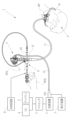
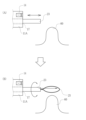
- FIG. 1 is a schematic diagram showing an endoscopy using an endoscope and an endoscopic treatment instrument device;
- FIG. 1 is a front view of an endoscope and a treatment instrument device for an endoscope;
- FIG. 4 is a cross-sectional view of the essential parts around the forceps plug in the endoscope;
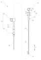
- 1 is a front view of an endoscopic treatment instrument device;
- FIG. 4 is an explanatory diagram of a state (A) in which the snare wire is spread and a state (B) in which the snare wire is contracted.
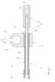
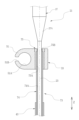
- FIG. 4 is a cross-sectional view of main parts of the oversheath;
- FIG. 4 is an exploded perspective view showing the configuration of the oversheath;
- FIG. 4 is an exploded perspective view showing the configuration of the outer sheath;
- FIG. 4 is an explanatory view showing a contracted state (A) and an extended state (B) of the first tubular portion of the outer sheath;
- FIG. 4 is an explanatory diagram showing the relationship between the inner diameter of the forceps channel and the outer diameter of the outer sheath;
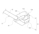
- FIG. 4 is a cross-sectional view of essential parts around an inner peripheral side sliding portion and a detachable member;
- FIG. 10 is a cross-sectional view of essential parts around the sealing member and the detachable member in a state where the third tubular portion of the inner sheath is inserted into the inner peripheral side sliding portion of the outer sheath;
- FIG. 4 is an explanatory view showing a contracted state (A) and an extended state (B) of the first tubular portion of the outer sheath;
- FIG. 4 is an explanatory diagram showing the relationship between the inner diameter of the forceps channel and the outer diameter of the
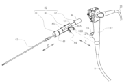
- FIG. 2 is a perspective view of the endoscopic treatment instrument with the inner sheath fitted thereto, and the outer sheath;
- Fig. 2 is a perspective view of a state in which the endoscopic treatment instrument is inserted into the oversheath; It is a perspective view of the detachable member periphery.
- Fig. 2 is a perspective view showing a state before the endoscope treatment instrument device is attached to the endoscope; It is explanatory drawing explaining the operation
- FIG. 4A is an explanatory view of treating a lesion using the endoscopic treatment device, showing a state in which the distal end of the flexible sheath is aligned with the position of the lesion (A), and a snare wire is protruded; It is explanatory drawing of a state (B).
- FIG. 10 is an explanatory view when treating a lesion using the endoscopic treatment device, and is an explanatory view of a state (A) in which the lesion is surrounded by a snare wire and a state (B) in which the lesion is excised. It is a front view of the treatment implement apparatus for endoscopes of 2nd Embodiment.
- FIG. 10 is an explanatory view when treating a lesion using the endoscopic treatment device, and is an explanatory view of a state (A) in which the lesion is surrounded by a snare wire and a state (B) in which the lesion is excised. It is a front view of the treatment implement
- FIG. 11 is a cross-sectional view of essential parts around an inner peripheral side sliding portion and a detachable member in a treatment instrument device for an endoscope according to a second embodiment;
- FIG. 11 is an explanatory diagram for explaining the operation when performing endoscopic examination and treatment in the first modified example;
- FIG. 11 is an explanatory diagram for explaining the operation when performing endoscopic examination and treatment in the second modified example;
- FIG. 11 is a plan view showing the arrangement of the outer sheath when the axial direction is not tilted (A) and when the axial direction is tilted in the third modified example;
- FIG. 11 is a plan view showing the arrangement of an outer sheath in a fourth modified example;
- FIG. 11 is a perspective view of an endoscope and an endoscopic treatment instrument device in a fifth modified example
- FIG. 14 is a perspective view of the endoscope and the endoscopic treatment instrument device in the fifth modified example, viewed from another direction
- FIG. 11 is a plan view of an endoscopic treatment instrument device in a fifth modified example
- FIG. 11 is a perspective view of an endoscope and an endoscope instrument according to a third embodiment
- FIG. 11 is a perspective view of an endoscopic instrument according to a third embodiment
- FIG. 11 is a perspective view of an endoscope and an endoscope instrument according to a fourth embodiment
- FIG. 12 is a perspective view of the distal end portion of the endoscope according to the fourth embodiment
- FIG. 12 is an exploded perspective view of the distal end portion of the endoscope according to the fourth embodiment
- FIG. 11 is an explanatory diagram for explaining the operation of the endoscopic instrument in the fourth embodiment;
- an endoscope system 1 of the present invention includes an endoscope 2, a processor device 3, a light source device 4, a display 5, a UI (User Interface) 6, a suction device 7, and a high frequency power supply 8. , and an endoscopic treatment instrument device 9 and the like.
- the endoscope 2 is, for example, an endoscope for upper gastrointestinal tracts such as esophagus and stomach, and has an insertion section 11 inserted into the upper gastrointestinal tract of a patient P, who is a subject, and a proximal end portion of the insertion section 11. and a universal cord 13 connected to the operation unit 12 .
- the universal cord 13 is connected to external devices such as the processor device 3 and the light source device 4 via the connector 13A.
- the processor device 3 is electrically connected with the display 5 and UI6.
- the UI 6 has a keyboard, a mouse, a touch pad, a microphone, etc., and receives input operations from a doctor D who is an operator.
- the insertion section 11 is composed of a distal end portion 11A, a bending portion 11B, and a flexible tube portion 11C in order from the distal end side to the proximal end side.
- an observation window and an illumination window are provided on the distal end surface of the distal end portion 11A.
- An image sensor 14 (see FIGS. 17 and 18) is arranged behind the observation window, and a light guide (optical fiber) cable (not shown) is arranged behind the illumination window.
- Signal lines and light guide cables of the image sensor 14 pass through the insertion portion 11, the operation portion 12, the universal cord 13, and the connector 13A, and are connected to the processor device 3 and the light source device 4, respectively.
- the processor device 3 performs image processing and the like on the endoscopic image captured by the image sensor 14 and causes the display 5 to display the image.
- the bending portion 11B is connected to the distal end portion 11A so as to be bendable.
- the mouthpiece MP for the endoscope When inserting the insertion portion 11 of the endoscope 2 from the mouth M of the patient P, the mouthpiece MP for the endoscope is attached to the mouth of the patient P.
- the endoscopic mouthpiece MP has a conduit (not shown) through which the insertion section 11 is inserted. A part of the endoscopic mouthpiece MP is inserted into the mouth M of the patient P, and the patient P holds the inserted part in his/her mouth so that the mouth of the patient P is fitted with the mouthpiece. This allows the insertion portion 11 to be introduced into the body through the duct.
- the operation portion 12 is integrally provided with a treatment instrument introduction portion 12A.
- the treatment instrument introduction portion 12A is a protrusion that protrudes from the outer peripheral surface of the operation portion 12 .
- the treatment instrument introduction portion 12A includes a base 16 (see FIG. 3). One end of the forceps channel 15 connects to the forceps outlet 17 and the other end connects to the base 16 .
- the mouthpiece 16 has a flange portion 16A on its outer peripheral surface.
- the inner peripheral surface 16B of the mouthpiece 16 is continuous with the inner peripheral surface of the forceps channel 15 .
- a forceps plug 18 is attached to the mouthpiece 16 .
- the flange portion 16A locks the forceps plug 18 .
- the forceps plug 18 is made of an elastically deformable resin, rubber member, or the like.
- the forceps plug 18 includes, for example, a cylindrical plug body 18A, a cap 18B fitted with the plug body 18A, and an attachment arm 18C. Also, the cap 18B has a knob portion 18D protruding from the outer diameter.
- the mounting arm 18C connects the plug body 18A and the cap 18B.
- a slit valve 18E having a slit through which the treatment instrument body 21 is inserted is provided inside the plug body 18A.
- the cap 18B is provided with a treatment instrument insertion hole 18F.
- the treatment instrument insertion hole 18F is positioned coaxially with the inner peripheral surface 16B of the base 16. As described above, since the inner peripheral surface 16B of the mouthpiece 16 is continuous with the inner peripheral surface of the forceps channel 15, the treatment instrument insertion hole 18F serves as an introduction port to the forceps channel 15.
- the treatment instrument insertion hole 18F in this embodiment corresponds to the "forceps port" in the scope of claims.
- the forceps channel 15 is also used as a path for sucking contents such as body fluids such as blood and body wastes from the forceps outlet 17 and as a path for feeding a washing liquid such as water.
- a suction channel 19 branched from the forceps channel 15 is arranged in the operating portion 12 .
- One end of the suction channel 19 is connected to the forceps channel 15 and the other end is connected to an operation button 12B provided on the operation section 12 .
- the operation button 12B has a suction valve (not shown) provided inside.
- the suction valve is connected to the suction channel 19 in the operation part 12, and is connected to an external suction device via a conduit (not shown) arranged in the operation part 12, the universal cord 13, the connector 13A, and the like. 7 is connected.
- the suction device 7 is, for example, a suction pump that creates a negative pressure.
- the high-frequency power supply 8 is connected to the endoscopic treatment device 9 via a cable (not shown), and applies a high-frequency current to a snare wire 25 (described later) of the endoscopic treatment device 9 . As a result, the lesion can be resected.
- the endoscopic treatment instrument device 9 includes a treatment instrument main body 21 and an oversheath 22 .
- the treatment instrument main body 21 corresponds to a "treatment instrument for an endoscope" or a “treatment instrument main body” in the claims.
- the treatment instrument main body 21 is, for example, a high-frequency snare that can excise a lesion by applying a high-frequency current.
- the oversheath 22 is inserted into the forceps channel 15 in cooperation with the treatment instrument main body 21 .
- the treatment instrument main body 21 includes a flexible sheath 23, an operation wire 24, a snare wire 25 as a treatment section, and an operation section 26.
- the flexible sheath 23 is a tubular sheath made of flexible material such as soft resin, and is inserted into the forceps channel 15 of the endoscope 2 together with the oversheath 22 .
- the operating wire 24 is provided integrally with the snare wire 25 and is passed through the flexible sheath 23 .
- the operating portion 26 includes an operating portion main body 27 and a slider 28 slidably supported by the operating portion main body 27 .
- the operation portion main body 27 is connected to the proximal end portion of the flexible sheath 23 .
- a tapered portion 27A is provided at the distal end portion of the operation portion main body 27, the outer diameter of which gradually decreases from the proximal end side to the distal end side.
- the operation portion main body 27 is provided with a finger hook portion 27B and a cylindrical portion 27C parallel to the insertion direction Z.
- the slider 28 is engaged with the cylindrical portion 27C and slides in the axial direction of the flexible sheath 23 along the cylindrical portion 27C.
- the operator's thumb is put on the finger hooking portion 27B, and the forefinger and middle finger of the same operator are put on the slider .
- a base end of the operation wire 24 is fixed to the slider 28 . Therefore, the operation wire 24 is pushed and pulled in the axial direction within the flexible sheath 23 as the slider 28 slides.
- the snare wire 25 expands into a loop shape when it protrudes from the distal end of the flexible sheath 23 in the insertion direction Z due to the push-pull operation of the operation wire 24 . This allows the snare wire 25 to surround the lesion.
- the snare wire 25 is contracted when it is housed inside the flexible sheath 23 by pushing and pulling the operating wire 24 as the slider 28 slides.
- the oversheath 22 includes an outer sheath 31, an inner sheath 32, and a detachable member 33.
- the outer sheath 31 is integrally provided with a first tubular portion 41, a second tubular portion 42, a connecting member 43, and a sealing member 44.
- the first tubular portion 41, the second tubular portion 42, the connecting member 43, and the sealing member 44 are made of a soft material such as soft resin.
- the length L11 of the first tubular portion 41 in the insertion direction Z is shorter than the length L12 of the flexible sheath 23 (see FIG. 4).
- the first tubular portion 41 is a flexible tubular sheath, through which the flexible sheath 23 of the treatment instrument main body 21 is inserted (see FIG. 14).
- the outer peripheral surface of the first tubular portion 41 is an outer peripheral sliding portion 41A.
- the outer peripheral side sliding portion 41A is formed to match the inner peripheral surface of the treatment instrument insertion hole 18F, and has an outer diameter slightly larger than the hole diameter of the treatment instrument insertion hole 18F.
- the slightly larger outer diameter referred to here means an outer diameter within a range in which the hole diameter of the treatment instrument insertion hole 18F expands due to elastic deformation. Thereby, the outer peripheral side sliding portion 41A slides on the inner peripheral surface of the treatment instrument insertion hole 18F.
- the first tubular portion 41 is composed of a small-diameter tube 45A, a large-diameter tube 45B, and a grip member 45C.
- the large-diameter tube 45B has a length in the axial direction, that is, the insertion direction Z, which is equal to or slightly shorter than that of the small-diameter tube 45A.
- the first tubular portion 41 has a double-tube structure whose length in the insertion direction Z can be expanded and contracted.
- the large-diameter tube 45B covers the small-diameter tube 45A and can move in the insertion direction Z relative to the small-diameter tube 45A.
- the grip member 45C has an outer diameter larger than that of the large-diameter tube 45B, and the large-diameter tube 45B is fixed to its inner peripheral surface. The grip member 45C moves integrally with the large-diameter tube 45B.
- the first tubular portion 41 normally covers the small-diameter tube 45A over the entire large-diameter tube 45B. That is, the length in the insertion direction Z of the first tubular portion 41 is approximately equal to the length in the insertion direction Z of the small-diameter tube 45A.
- FIG. 9B when the user grips the grip member 42C and moves the large-diameter tube 45B to the distal end side, the portion where the large-diameter tube 45B and the small-diameter tube 45A overlap becomes less. That is, the length in the insertion direction Z of the first tubular portion 41 is longer than the state shown in FIG. 9(A).
- the length in the insertion direction Z of the first tubular portion 41 is reduced. In this manner, the first tubular portion 41 can be expanded and contracted.
- the forceps channel 15 of the endoscope 2 has a first inner diameter portion 15A located on the side of the forceps opening, that is, the treatment instrument insertion hole 18F, and a position closer to the distal end portion 11A than the first inner diameter portion 15A. and a second inner diameter portion 15B.
- the inner diameter D22 of the second inner diameter portion 15B is smaller than the inner diameter D21 of the first inner diameter portion 15A.
- FIG. 10 shows a state in which the detachable member 33 is not engaged with the forceps plug 18 for convenience of explanation.
- the forceps channel 15 has a branch portion 15C where the suction channel 19 joins.
- 15 C of branch parts are formed, for example from hard materials, such as a metal pipe.
- a portion between the branched portion 15C and the mouthpiece 16 (see FIG. 3) is a first inner diameter portion 15A, and a portion between the branched portion 15C and the forceps outlet 17 is a second inner diameter portion 15B.
- the first inner diameter portion 15A and the first inner diameter portion 15A are formed, for example, from a resin pipe.
- the outer diameter D11 (see FIG. 6) of the first tubular portion 41 is smaller than the inner diameter D21 of the first inner diameter portion 15A and larger than the inner diameter D22 of the second inner diameter portion 15B. That is, the first tubular portion 41 can be inserted from the treatment instrument insertion hole 18F to the first inner diameter portion 15A, but cannot be inserted into the second inner diameter portion 15B. Insertion is restricted.
- the second tubular portion 42 is provided at the base end portion of the first tubular portion 41 and is made of a material harder than the first tubular portion 41 .
- the second tubular portion 42 has a cylindrical shape with an outer diameter larger than that of the first tubular portion 41 .
- the first tubular portion 41 and the second tubular portion 42 are connected via a connecting member 43 .
- the connecting member 43 is formed in a cylindrical shape with an outer diameter larger than that of the second tubular portion 42, and the first tubular portion 41 is fixed on the distal end side and the second tubular portion 42 is fixed on the proximal end side.
- a groove 43A (see FIG. 9) is formed in the outer peripheral surface of the connecting member 43 .
- the inner peripheral surface of the second tubular portion 42 is an inner peripheral sliding portion 42A that allows the treatment instrument main body 21 to move forward and backward with respect to the forceps channel 15 .
- the inner peripheral side sliding portion 42A slides on the inner sheath 32 fitted to the treatment instrument main body 21 . Therefore, the inner sheath 32 and the treatment instrument main body 21 slide integrally with respect to the outer sheath 31 .
- the treatment instrument insertion hole 18 ⁇ /b>F is an introduction port to the forceps channel 15 and slides on the outer peripheral side sliding portion 41 ⁇ /b>A of the first tubular portion 41 .
- the inner sheath 32 slides against the first tubular portion 41 that slides on the treatment instrument insertion hole 18F, that is, the outer sheath 31 . Therefore, the inner peripheral side sliding portion 42A enables the treatment instrument main body 21 to advance and retreat together with the inner sheath 32 with respect to the forceps channel 15 .
- the inner peripheral side sliding portion 42A has a function of positively moving the treatment instrument main body 21 by sliding (that is, resistance to the inner sheath 32 or the treatment instrument main body 21). force is small), the outer peripheral side sliding portion 41A has a function of substantially not moving forward or backward with respect to the forceps plug 18 (that is, the resistance against the forceps plug 18 is large).
- the sealing member 44 is provided at the proximal end of the second tubular portion 42 .
- the seal member 44 is formed in a cylindrical shape, and the second tubular portion 42 is fixed to the distal end side of the inner peripheral surface 44A.
- An annular protrusion 44B protruding radially inward is formed at the base end portion of the inner peripheral surface 44A.
- the inner diameter of the projection 44B is slightly smaller than the outer diameter of the third tubular portion 47 of the inner sheath 32, which will be described later.
- the protrusion 44B is in close contact with the third tubular portion 47, so that the outer sheath
- the gap between 31 and inner sheath 32 is filled. This improves the airtightness between the treatment instrument main body 21 and the oversheath 22 during various treatments, prevents the escape of air and carbon dioxide in the stomach and the leakage of the contents, and is comfortable for doctors and caregivers. It is possible to secure a space for performing various treatments in the space and prevent contamination due to leakage.
- the detachable member 33 is fitted to the outer peripheral surface 44C of the seal member 44 .
- the inner sheath 32 is integrally provided with a fitting portion 46 and a third tubular portion 47 .
- the inner peripheral surface of the fitting portion 46 has a tapered portion 46A and a circumferential portion 46B.
- the tapered portion 46A is located at the proximal end portion of the fitting portion 46 .
- the tapered portion 46A of the fitting portion 46 is fitted onto the tapered portion 27A of the treatment instrument main body 21 .
- the fitting portion 46 is not limited to this, and may be fitted to the operating portion 26 of the treatment instrument main body 21 or the flexible sheath 23 .
- the third tubular portion 47 is formed in a tubular shape covering at least a portion of the flexible sheath 23 .
- 47 A of outer peripheral surfaces of the 3rd tubular part 47 are formed according to the internal diameter of 42 A of inner peripheral side sliding parts (refer FIG. 6) mentioned above. As a result, the third tubular portion 47 slides on the inner peripheral slide portion 42A.
- the oversheath 22 has a third tubular portion 47 that covers at least a portion of the flexible sheath 23 , and a fitting portion 46 of the inner sheath 32 that is attached to the operation portion 26 of the treatment instrument main body 21 . be fitted. Then, the flexible sheath 23 is inserted into the first tubular portion 41, and the third tubular portion 47 is inserted into the inner sliding portion 42A (see FIG. 11).
- the treatment instrument main body 21 is rotatable and movable with respect to the oversheath 22 within a range in which the third tubular portion 47 and the inner peripheral sliding portion 42A slide. Furthermore, in this state, the snare wire 25 can be expanded or contracted by pushing and pulling the operating wire 24 as the slider 28 slides.
- the outer diameter of the fitting portion 46 is larger than the outer diameter of the third tubular portion 47, when the inner sheath 32 and the treatment instrument main body 21 are slid toward the distal end side in the insertion direction Z with respect to the outer sheath 31, The fitting portion 46 abuts the proximal end of the outer sheath 31 . This allows the user to recognize that the inner sheath 32 and the treatment instrument main body 21 cannot be slid further toward the distal side in the insertion direction Z with respect to the outer sheath 31 .
- the length L13 of the third tubular portion 47 in the insertion direction Z is longer than the range in which the treatment instrument main body 21 advances and retreats with respect to the forceps channel 15 .
- the length L13 of the third tubular portion 47 is longer than the range in which the snare wire 25 projects and moves with respect to the distal end portion 11A. Assuming that the range in which the treatment instrument main body 21 advances and retreats with respect to the forceps channel 15 is 50 mm, the length L13 is preferably 75 mm, for example.
- the detachable member 33 is provided integrally with the outer sheath 31 and detachably engages with the forceps plug 18 attached to the forceps channel 15 .
- the outer sheath 31 is attached to the endoscope 2 via the detachable member 33 .
- the detachable member 33 has a first engaging portion 51 that engages the forceps plug 18 and a second engaging portion 52 that engages with a portion of the endoscope 2 .
- the first engaging portion 51 is a C-shaped engaging portion (see also FIGS. 11 and 12).
- the first engaging portion 51 has, for example, an inner peripheral surface 51A, a notch 51B, and a recessed portion 51C.
- the inner peripheral surface 51A has an inner diameter that matches the outer diameter of the forceps plug 18 .
- the notch 51B is continuous with the inner peripheral surface 51A and formed with a width smaller than the outer diameter of the forceps plug 18 .
- the first engaging portion 51 When the notch 51B is aligned with the forceps plug 18 and pushed in, the first engaging portion 51 is elastically deformed to widen the width of the notch 51B. When the first engaging portion 51 is further pushed, the notch 51B climbs over the forceps plug 18, and the inner peripheral surface 51A engages with the outer peripheral surface of the forceps plug 18. As shown in FIG. Thereby, the first engaging portion 51 engages with the forceps plug 18 .
- the recess 51C is arranged at a position symmetrical to the notch 51B with the center of the inner peripheral surface 51A interposed therebetween.
- the mounting arm 18C (see FIG. 3) is positioned within the notch 51B, and the knob 18D (see FIG. 3) is positioned within the recess 51C.
- the recessed portion 51C is a recessed portion that is continuous with the inner peripheral surface 51A and has a circular shape.
- the concave portion 51C is arranged at a position corresponding to the knob portion 18D of the forceps plug 18. As shown in FIG.
- the recessed portion 51C locks the knob portion 18D. This restricts the attachment/detachment member 33 from rotating around the forceps plug 18 . Also, in this case, the notch 51B may engage the mounting arm 18C of the forceps plug 18 .
- the detachable member 33 is fitted to the seal member 44 of the outer sheath 31 as described above.
- the attachment direction X of the attachment/detachment member 33 to the forceps plug 18 is the direction of the notch 51B when viewed from the center of the inner peripheral surface 51A.
- This attachment direction X (see FIG. 11) is orthogonal to the insertion direction Z, ie, the axial direction of the outer sheath 31 .
- the second engaging portion 52 has a pair of clamping pieces 52A and 52B that clamp a part of the endoscope 2.
- the pair of clamping pieces 52A and 52B are formed at intervals matching the treatment instrument introduction portion 12A of the endoscope 2 .
- the detachable member 33 has a structure in which a first engaging portion 51 and a second engaging portion 52 are overlapped.
- the endoscopic treatment instrument device 9 is inserted into the forceps channel 15 of the endoscope 2 with the inner sheath 32 and the treatment instrument body 21 inserted into the outer sheath 31 .
- the first tubular portion 41 of the outer sheath 31 is inserted into the forceps channel 15 through the treatment instrument insertion hole 18F or the like formed inside the forceps plug 18 .
- the forceps plug 18 By pushing the detachable member 33 from the radial direction of the forceps plug 18, the forceps plug 18 is fitted to the inner peripheral surface 51A of the first engaging portion 51, and the clamping pieces 52A and 52B of the second engaging portion 52 are engaged. to hold the treatment instrument introduction portion 12A.
- the detachable member 33 can be engaged with the forceps plug 18 and the treatment instrument introducing portion 12A. That is, the outer sheath 31 can be attached to the endoscope 2 via the detachable member 33 .
- the first resistance force when advancing and retreating the first tubular portion 41 with respect to the forceps channel 15 is R1
- the force when advancing and retreating the inner sheath 32 and the treatment instrument main body 21 with respect to the second tubular portion is R2
- the first resistance R1 is greater than the second resistance R2.
- the first resistance R1 here is mainly the frictional force generated between the forceps plug 18 and the outer sheath
- the second resistance R2 is mainly the friction between the outer sheath 31 and the inner sheath 32.
- the first resistance R1 is the frictional force generated between In order to make the first resistance R1 larger than the second resistance R2, for example, a material with a smooth surface (low friction) is selected as the sealing member 44 of the outer sheath 31,
- the dimensional difference from the outer diameter of the tubular portion 41 may be adjusted.
- the outer diameter of the outer peripheral side sliding portion 41A of the outer sheath 31 is set to the maximum of the forceps channel 15.
- the clearance between the inner peripheral surface 16B of the mouthpiece 16 and the outer diameter of the outer peripheral side sliding portion 41A of the outer sheath 31 is set to the inner diameter of the inner peripheral side sliding portion 42A of the outer sheath 31 and the third clearance of the inner sheath 32.
- the first resistance R1 can be made larger than the second resistance R2.
- the doctor D inserts the insertion portion 11 of the endoscope 2 into the body of the patient P, observes the endoscopic image captured by the image sensor 14, and observes the lesion 60 (see FIGS. 18 and 19). area of interest and determine where to treat. Then, as shown in FIG. 17, first, the doctor D inserts the outer sheath into the forceps channel 15 while maintaining the state in which the flexible sheath 23 and the inner sheath 32 of the instrument main body 21 are inserted into the outer sheath 31. 31 and flexible sheath 23 are inserted.
- the doctor D causes the snare wire 25 to contract by operating the operating section 26 .
- the doctor D attaches the outer sheath 31 to the operating portion 12 of the endoscope 2 by engaging the detachable member 33 with the forceps plug 18 .
- the treatment instrument main body 21 can advance/retreat and rotate with respect to the outer sheath 31 within the range in which the third tubular portion 47 and the inner peripheral sliding portion 42A slide. That is, when the oversheath 22 and the treatment instrument main body 21 are inserted into the forceps channel 15, the treatment instrument main body 21 can advance, retreat, and rotate with respect to the forceps channel 15 within a certain range.
- the doctor D advances and retreats the treatment instrument main body 21 with respect to the outer sheath 31 while observing the endoscopic image captured by the image sensor 14 , and moves the distal end of the flexible sheath 23 to the position of the lesion 60 .
- the positions of the parts can be aligned (the state shown in FIG. 18(A)).
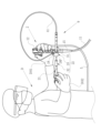
- the doctor D can operate by holding the operation section 12 of the endoscope 2 with one hand DH1 and holding the treatment instrument body 21 with the other hand DH2.
- the operating portion 26 is operated with the other hand DH2 to protrude the snare wire 25, or the treatment instrument main body 21 is rotated with respect to the outer sheath 31, and the position of the snare wire 25 is aligned with the position of the lesion 60. (state shown in FIG. 18(B)). Furthermore, the doctor D bends the bending portion 11B by operating the endoscope 2 with one hand DH1, for example. As a result, the position of the snare wire 25 is brought closer to the position of the lesion 60, and the lesion 60 is surrounded by the loop of the snare wire 25 (state shown in FIG. 19(A)).
- the doctor D manipulates the snare wire 25 to pull it into the flexible sheath 23 to strangle the lesion 60, and then manipulates the high-frequency power supply 8 to apply a high-frequency current to the snare wire 25, so that the lesion is stretched.
- 60 can be excised from the body of the patient P (state shown in FIG. 19(B)).
- the doctor D when performing a treatment using the oversheath 22 and the endoscopic treatment instrument device 9 including the same, moves the treatment instrument body 21 relative to the forceps channel 15 . It is possible to easily perform a plurality of types of treatment such as forward/backward movement and rotation of the snare wire 25 as well as contraction and expansion of the snare wire 25 . In addition, doctor D can perform the above treatment alone. As a result, it is possible to operate the treatment instrument without the need for cooperation, and if the doctor is the main operator, the treatment can be performed by a small number of people.
- the oversheath 22 includes a first tubular portion 41 that slides on the inner peripheral surface of the forceps port, and a second tubular portion 42 that allows the treatment instrument main body 21 to move forward and backward with respect to the forceps channel 15 . Therefore, there is no need to provide a dedicated component in the treatment instrument main body 21, and treatment can be easily performed by combining it with the oversheath 22. - ⁇ That is, the oversheath 22 can correspond to a plurality of types of endoscopic treatment tools.
- the oversheath 22 is fitted over the outer sheath 31 integrally provided with the first tubular portion 41 and the second tubular portion 42 and the treatment instrument main body 21, slides on the second tubular portion 42, and is movable. Since the flexible sheath 23 is provided with the inner sheath 32 that covers at least part of the flexible sheath 23, it is possible to handle a plurality of types of endoscopic treatment tools and easily operate the treatment tools.
- the oversheath 22 can be attached to the operation portion 12 via the attachment/detachment member 33 that engages with the forceps plug 18 , the operation performed by the doctor D is concentrated near the operation portion 12 , and the operation of the treatment instrument main body 21 is reduced. can be stably performed. Further, since the detachable member 33 has a first engaging portion 51 that engages with the forceps plug 18 and a second engaging portion 52 that engages with a part of the endoscope 2, the oversheath 22 can be operated easily. It can be more reliably attached to the portion 12 .
- the treatment Movement of the oversheath 22 can be restricted when the tool body 21 is being operated. Thereby, the operation of the treatment instrument main body 21 can be performed more stably.
- the over-sheath 22 is fitted over the treatment instrument body 21, and the treatment instrument is operated by sliding the inner sheath 32 covering at least a portion of the flexible sheath 23 with respect to the outer sheath 31.
- the present invention is not limited to this, and may be configured without an inner sheath, as in an endoscopic treatment instrument device 71 shown in FIG. 20 .
- the endoscope treatment instrument device 71 includes a treatment instrument main body 21 and an oversheath 72 .
- the oversheath 72 includes an outer sheath 73 and a detachable member 33 .
- the configuration of the treatment instrument main body 21 and the attachment/detachment member 33 is the same as that of the first embodiment, and the description thereof will be omitted.
- parts similar to those of the outer sheath 31 in the first embodiment are denoted by the same reference numerals, and descriptions thereof are omitted.
- the outer sheath 73 is integrally provided with the first tubular portion 41, the second tubular portion 74, the connecting member 43, and the sealing member 75. As shown in FIG.
- the first tubular portion 41, the second tubular portion 74, the connecting member 43, and the sealing member 75 are made of a soft material such as soft resin.
- the second tubular portion 74 is provided at the proximal end portion of the first tubular portion 41 and is made of a material harder than the first tubular portion 41 .
- the first tubular portion 41 and the second tubular portion 74 are connected via the connecting member 43 .
- the inner peripheral surface of the second tubular portion 74 is an inner peripheral side sliding portion 74A that allows the treatment instrument body 21 to move forward and backward with respect to the forceps channel 15 .
- the inner peripheral sliding portion 42A slides on the flexible sheath 23 of the treatment instrument main body 21 .
- the first tubular portion 41 slides on the treatment instrument insertion hole 18F, which is an introduction port to the forceps channel 15.
- the inner peripheral sliding portion 74A enables the treatment instrument main body 21 to move forward and backward with respect to the forceps channel 15 .
- the outer shape, material, etc. of the second tubular portion 74 are the same as those of the second tubular portion 42 of the outer sheath 31 in the first embodiment.
- the sealing member 75 is provided at the proximal end of the second tubular portion 74 .
- the sealing member 75 is formed in a cylindrical shape, and the second tubular portion 74 is fixed to the distal end side of the inner peripheral surface 75A.
- An annular protrusion 75B protruding radially inward is formed at the base end portion of the inner peripheral surface 75A.
- the inner diameter of the protrusion 75B is slightly smaller than the outer diameter of the flexible sheath 23.
- the protrusions 75B are in close contact with the flexible sheath 23, so that the gap between the outer sheath 73 and the flexible sheath 23 is filled.
- This improves the airtightness between the treatment instrument main body 21 and the oversheath 72 during various treatments, prevents the air and carbon dioxide in the stomach from escaping and the contents from leaking, and is comfortable for the doctor or the caregiver. It is possible to secure a space for performing various treatments in the space and prevent contamination due to leakage.
- the detachable member 33 is fitted to the outer peripheral surface 75 ⁇ /b>C of the seal member 75 .
- the first resistance when moving the first tubular portion 41 forward and backward with respect to the forceps channel 15 is the force applied to the second tubular portion 74 . It is larger than the second resistance force when moving the main body 21 back and forth.
- the first resistance here is mainly the frictional force generated between the forceps plug 18 and the outer sheath 73
- the second resistance is mainly the friction between the outer sheath 73 and the flexible sheath 23. is the frictional force generated between
- the detachable member 33 can be engaged with the forceps plug 18 and the treatment instrument introducing portion 12A, as in the first embodiment. That is, the outer sheath 73 can be attached to the endoscope 2 via the detachable member 33 .
- the treatment instrument main body 21 can move forward, backward, and rotate with respect to the outer sheath 73 within the range in which the flexible sheath 23 and the inner peripheral sliding portion 74A slide. That is, when the oversheath 72 and the treatment instrument main body 21 are inserted into the forceps channel 15, the treatment instrument main body 21 can advance/retreat and rotate with respect to the forceps channel 15 within a certain range. Therefore, in addition to the operation of the endoscope 2, the doctor, who is the user, can move the treatment instrument main body 21 forward and backward with respect to the forceps channel 15 and rotate it, and contract and extend the snare wire 25, in addition to the operation of the endoscope 2, as in the first embodiment. It is possible to easily perform a plurality of types of treatment called opening.
- the doctor D performs a plurality of types of treatment by himself.
- the assistant H can operate the endoscopic treatment instrument device 9 . That is, with the configuration of the endoscopic treatment instrument device 9 of the first and second embodiments, the caregiver H can operate the treatment instrument main body 21 to slide and rotate with respect to the forceps channel 15, contract the snare wire 25, and It is possible to perform a plurality of types of treatment such as widening and energization of the snare wire 25 by the high-frequency power source 8 .
- the types of treatment instrument operations that can be performed by the caregiver are increased, and the treatment instrument operation can be performed without the need for cooperation.
- the forceps plug 18 is disengaged from the attachment/detachment member 33 so that the caregiver H can freely handle the oversheath 22 and the instrument main body 21. 22 is preferably removed.
- the position of the doctor D and the position of the helper H are close to each other, but the position of the doctor D and the position of the helper H may be separated.
- the doctor D and the helper H may cooperate to perform the treatment.
- the doctor D operates the endoscope 2, inserts the oversheath 22 into the forceps channel 15, energizes the snare wire 25 by the high-frequency power source 8, and the like.
- the operations related to the endoscopic treatment instrument device 9 can be divided among them, such as the operation of advancing/retreating and rotating the main body 21 and the contraction and expansion of the snare wire 25 .
- the forceps plug 18 is disengaged from the attachment/detachment member 33 so that the caregiver H can freely handle the oversheath 22 and the instrument main body 21. 22 is preferably removed.
- the position of the doctor D and the position of the helper H are close to each other, but the position of the doctor D and the position of the helper H may be separated.
- the detachable member 33 is arranged parallel to the mounting direction X to the forceps plug 18 .
- the mounting direction X is orthogonal to the insertion direction Z, ie, the axial direction of the outer sheath 31 .
- the axial direction (insertion direction Z) of the outer sheath 31 is orthogonal.
- the direction toward the mounting arm 18C may be inclined.
- a plane S passing through the center of the detachable member 33 (a plane orthogonal to the insertion direction Z) is inclined with respect to the mounting direction X at an inclination angle ⁇ .
- the axial direction (insertion direction Z) of the outer sheath 31 is arranged at a position inclined at an inclination angle ⁇ from a direction orthogonal to the mounting direction X.
- one may be selected from a plurality of detachable members 33 having different inclination angles ⁇ with respect to the mounting direction X so that the inclination angle ⁇ can be changed according to the user's preference.
- the inclination angle ⁇ is preferably about 30° or 45°, for example.
- the detachable member 33 may be configured to be inclined with respect to the axial direction Y of the forceps plug 18 .
- a plane S passing through the center of the detachable member 33 is inclined at an inclination angle ⁇ with respect to the axial direction Y of the forceps plug 18 .
- the endoscope treatment instrument device 81 includes a treatment instrument main body 21 and an oversheath 82 .
- the oversheath 82 includes an outer sheath 31 , an inner sheath 32 and a detachable member 83 .
- the outer sheath 31 and the inner sheath 32 have the same configuration as the oversheath 22 of the first embodiment.
- the oversheath 82 is not limited to this, and the detachable member 83 may be combined with the configuration including the outer sheath 73 and the like similar to the oversheath 72 in the second embodiment.
- the detachable member 83 is provided integrally with the outer sheath 31 and detachably engages with the operating portion 12 .
- the outer sheath 31 is attached to the endoscope 2 via the detachable member 83 .
- the detachable member 83 has an engaging portion 84 and a fitting portion 85 .
- the engaging portion 84 engages with the operating portion 12 .
- the engagement portion 84 engages with the cylindrical outer peripheral surface of the operation portion 12 excluding the operation dial, the button, and the treatment instrument introduction portion 12A.
- the engaging portion 84 is a C-shaped engaging portion.
- the engaging portion 84 has, for example, an inner peripheral surface 84A and a notch 84B.
- the inner peripheral surface 84A is formed to have an inner diameter that matches the outer diameter of the operating portion 12 .
- the notch 84B is continuous with the inner peripheral surface 84A and formed to have a width smaller than the outer diameter of the operating portion 12 .
- the fitting portion 85 is fitted to the sealing member 44 (see FIG. 6) of the outer sheath 31.
- the mounting direction X of the detachable member 83 with respect to the operating portion 12 is the direction of the notch 84B when viewed from the center of the inner peripheral surface 84A. This attachment direction X is orthogonal to the insertion direction Z, ie, the axial direction of the outer sheath 31 .
- the engaging part 84 When the notch 84B is aligned with the position of the operation part 12 and pushed in, the engaging part 84 is elastically deformed to widen the width of the notch 84B. When the engaging portion 84 is further pushed, the notch 84B climbs over the operating portion 12, and the inner peripheral surface 84A is fitted with the outer peripheral surface of the operating portion 12. As shown in FIG. Thereby, the engaging portion 84 engages with the operating portion 12 . That is, the oversheath 82 can be attached to the operating portion 12 via the detachable member 83 . Therefore, operations performed by the doctor D are concentrated near the operation unit 12, and the operation of the treatment instrument main body 21 can be stably performed. In addition, since the outer sheath 31 and the inner sheath 32 constituting the oversheath 22 are configured in the same manner as in the first embodiment, the same effect can be obtained regarding the operation of the treatment instrument.
- the oversheath 82 is not limited to the above configuration, and a configuration including the outer sheath 73 and the like similar to the oversheath 72 in the second embodiment may be combined with the detachable member 83 . As a result, the same effects as those of the second embodiment can be obtained through the operation of the treatment instrument.
- the configuration of attaching the oversheath and the endoscopic treatment instrument device including the oversheath to the endoscope via the detachable member is exemplified.
- a configuration may be adopted in which an endoscopic instrument other than the oversheath is attached to the endoscope via the detachable member.
- a catheter device 92 is attached via a detachable member 91 .
- the catheter device 92 corresponds to an endoscopic instrument in the claims.
- the catheter device 92 includes a guide catheter 93, a guide catheter cock 94, and a guide wire 95.
- the guide catheter 93 is molded from a flexible synthetic resin material such as a fluorine-based resin or a nylon-based resin.
- a guide wire lumen is formed over the entire length of the guide catheter 93 .
- a guide catheter cock 94 is integrally provided at the proximal end of the guide catheter 93 .
- the guide catheter cock 94 has a guide wire opening 94a communicating with the guide wire lumen and a liquid feed cap 94b.
- the guide wire 95 is inserted into the guide wire lumen of the guide catheter 93 through the guide wire opening 94a.
- the guide catheter 93 is inserted into the forceps channel 15 of the endoscope 2 through the treatment instrument insertion hole 18F.
- the guide wire 95 protrudes from the distal end portion 11A of the endoscope 2 while being inserted into the guide wire lumen of the guide catheter 93 .
- the doctor grasps and operates the guide catheter 93 and the guide catheter cock 94 .
- the guide wire 95 as a guide, the guide catheter 93 is guided into the body cavity.
- the guide catheter 93 can be used to deliver liquid into the body cavity.
- the guide catheter cock 94 corresponds to a treatment instrument operating section in the claims, and is an operating section that operates the catheter device 92 .
- the detachable member 91 has a first engaging portion 51 and a second engaging portion 52, like the detachable member 33 in the first and second embodiments.
- the first engaging portion 51 engages with the forceps plug 18, and the second engaging portion 52 engages with the treatment instrument introducing portion 12A.
- the treatment instrument introduction portion 12A is located on the root side of the forceps plug 18 .
- the detachable member 91 is provided integrally with the guide catheter cock 94 and is detachably engaged with the forceps plug 18 . Specifically, the detachable member 91 is fitted with the outer peripheral surface of the guide catheter cock 94 .
- the guide catheter cock 94 is arranged at a position where the axial direction (insertion direction Z) of the guide catheter cock 94 intersects the attachment/detachment direction (attachment direction X) of the detachable member 83 (see FIG. 30). .
- the doctor When performing treatment with the catheter device 92 , the doctor attaches the guide catheter cock 94 to the operation section 12 of the endoscope 2 by engaging the detachable member 91 with the forceps plug 18 . As a result, the doctor can easily perform treatment using the catheter device 92, such as guiding the guide catheter 93 into the body cavity, in addition to operating the endoscope 2.
- FIG. 1 When performing treatment with the catheter device 92 , the doctor attaches the guide catheter cock 94 to the operation section 12 of the endoscope 2 by engaging the detachable member 91 with the forceps plug 18 .
- the catheter device 92 can be attached to the operating section 12 via the detachable member 91, operations performed by the doctor are concentrated near the operating section 12, and the catheter device 92 can be stably operated. Moreover, since the detachable member 91 has the first engaging portion 51 and the second engaging portion 52 , the catheter device 92 can be securely attached to the operating portion 12 . In FIG. 29, the guide catheter cock 94 is arranged in a direction that intersects the treatment instrument introduction portion 12A. good too.
- the endoscope instrument to be attached to the endoscope via the detachable member is not limited to those exemplified in the above embodiments, and as shown in FIG. It is also possible to adopt a configuration in which the erector wire operation portion 112 is attached via 111 .
- the detachable member 111 has the same configuration as the detachable member 91 in the third embodiment.
- the erector wire operation unit 112 is connected to the erector operating wire 108 (see FIGS. 32 and 33) to operate the later-described erector 107 .
- the endoscope 100 includes an insertion section 101, an operation section 12, and a universal cord 13.
- the operation unit 12 and the universal cord 13 have the same configurations as those of the endoscope 2 of the first embodiment.
- the insertion portion 101 includes a distal end portion 102, a bending portion 11B, and a flexible tube portion 11C.
- the bending portion 11B and the flexible tube portion 11C have the same configuration as the insertion portion 11 in the endoscope 2 of the first embodiment.
- the distal end portion 102 is provided with an image sensor 103, an illumination optical system 104, and the like.
- the endoscope 100 is a side-viewing endoscope used as, for example, a duodenoscope, and a distal end portion 102 shown in FIGS. 32 and 33 has a configuration of a side-viewing endoscope.
- a forceps channel 15 is provided in the insertion section 101, like the insertion section 11 of the endoscope 2 of the first embodiment. One end of the forceps channel 15 is connected to the tip portion 102 and the other end is connected to the ferrule 16 .
- the distal end portion 102 has a distal end portion body 105 and a cap 106 and is configured by attaching the cap 106 to the distal end portion body 105 .
- a cap 106 is detachably attached to the tip body 105 .
- the tip body 105 is provided on the tip side of the bending portion 11B.
- the cap 106 is provided with a stand 107 , a stand operating wire 108 and a guide tube 109 .
- the forceps channel 15 guides the distal end portion 110A (see FIGS. 31 and 34) of the treatment instrument 110 into the distal end portion 102.
- the treatment instrument 110 is, for example, an imaging tube or a papillotomy knife.
- the cap 106 is formed in a substantially tubular shape with a closed tip side, and has a peripheral surface portion 106A and an end surface portion 106B.
- a substantially rectangular opening window 106C is formed in a portion of the peripheral surface portion 106A.
- the opening window 106C is an opening cut out from the peripheral surface portion 106A to the end surface portion 106B.
- the standing base 107 is rotatably attached inside the cap 106 via a rotating shaft 107A, and is movable between the standing position and the reclined position.
- the end of the stand 107 is connected to the tip of the stand operating wire 108 .
- the erector operation wire 108 is an operation wire for performing an operation to rotate the erector 107 .
- the erector operating wire 108 is inserted inside the guide tube 109 and advances and retreats inside the guide tube 109 .
- the erector operation wire 108 and the guide tube 109 are led out from the proximal end of the cap 106 , and the part led out from the cap 106 is arranged along the outer peripheral surface of the insertion section 101 .
- the treatment instrument outlet 15A of the forceps channel 15 communicates with the inside of the cap 106 and the opening window 106C. Also, the image sensor 103 and the illumination optical system 104 are exposed through the opening window 106C.
- the cap 106 is coaxially attached to the tip body 105 .
- the tip body 105 is provided with a signal cable 113 and a light guide 114 in addition to the image sensor 103 and the illumination optical system 104 .
- the signal cable 113 and the light guide 114 are connected to the processor device 3 and the light source device 4 through the insertion portion 101, the operation portion 12, connectors (not shown), and the like.
- the processor device 3 performs image processing or the like on the imaging signal acquired by the image sensor 103 and causes the display 5 to display an observed image.
- the light guide 114 is composed of an optical fiber cable or the like, transmits the illumination light emitted by the light source device 4 , and irradiates the observation target with the illumination light via the illumination optical system 104 .
- the erector wire operation unit 112 performs an operation of pushing and pulling the erector operation wire 108 in accordance with the rotation operation of the operation lever 112A.
- the raising table 107 is rotated by pushing and pulling the raising table operation wire 108 .
- the stand 107 raises the distal end portion 110A of the treatment instrument 110 led out from the treatment instrument outlet 15A.
- the raising table 107 rotates from the lying position (the position indicated by the solid line) to the standing position (the position indicated by the two-dot chain line). Thereby, the lead-out direction of the distal end portion 110A of the treatment tool 110 led out to the treatment tool lead-out port 15A can be changed.
- the erector wire operation section 112 corresponds to the treatment instrument operation section in the claims, and is an operation section for operating the treatment instrument 110 .
- the detachable member 111 has a first engaging portion 51 and a second engaging portion 52, like the detachable member 33 in the first and second embodiments and the detachable member 91 in the third embodiment. have.
- the detachable member 111 is provided integrally with the erector wire operation portion 112 and is detachably engaged with the forceps plug 18 . Specifically, the detachable member 111 is fitted to the outer peripheral surface of the erector wire operation portion 112 .
- the doctor When a treatment is performed using the treatment instrument 110 and the wire operation section 112 for the stand, the doctor operates the wire operation section 112 for the stand by operating the endoscope 100 by engaging the detachable member 111 with the forceps plug 18 . Attach to part 12 .
- the doctor can easily perform a treatment using the treatment instrument 110 and the wire operation section 112 for the erector, such as an operation to rotate the erector 107 , in addition to the operation of the endoscope 100 .
- the detachable member 111 has the same configuration as the detachable member 91 in the third embodiment, the endoscope 100 and the erector wire operation section 112 in the present embodiment are also the same as in the third embodiment. effect can be obtained.
- the forceps port is exemplified by the treatment instrument insertion hole 18F, but the forceps port is not limited to this. (See FIG. 3).
- the treatment instrument main body 21 is provided with the snare wire 25 as the treatment portion, and a high-frequency snare that expands in a loop shape when protruding from the distal end of the flexible sheath 23 due to the push-pull operation of the operation wire 24.
- the treatment tool main body 21 is not limited to this, and may be, for example, a puncture needle, a treatment tool having an ultrasonic transducer, or the like.
- biopsy forceps for pinching and excising living tissue in the body For example, biopsy forceps for pinching and excising living tissue in the body, high-frequency scissors forceps for applying high-frequency current to the treatment portion, and high-frequency needle-like forceps.
- a knife or the like may be applied as the treatment instrument main body 21 .
- the endoscopic instrument attached to the endoscope via the detachable member is not limited to those according to the third and fourth embodiments.
- a treatment instrument equipped with an endoscope, a high-frequency scissors forceps, a high-frequency needle-like knife, and the like may be applied.
- an upper gastrointestinal endoscope is used as an example of an endoscope, but the endoscope is not limited to this and may be an endoscope equipped with a forceps plug, such as a bronchoscope or a lower gastrointestinal endoscope.
- a tube endoscope may be used.
- Endoscope System 2 Endoscope 3 Processor Device 4 Light Source Device 5 Display 6 UI (User Interface) 7 suction device 8 high-frequency power supply 9 endoscope treatment instrument device 11 insertion portion 11A distal end portion 11B bending portion 11C flexible tube portion 12 operation portion 12A treatment instrument introduction portion 12B operation button 13 universal cord 13A connector 14 image sensor 15 forceps channel 15A First inner diameter portion 15B First inner diameter portion 15B Second inner diameter portion 15C Branch portion 16 Mouthpiece 16A Flange portion 16B Inner peripheral surface 17 Forceps outlet 18 Forceps plug 18A Plug body 18B Cap 18C Mounting arm 18D Knob portion 18E Slit valve 18F Treatment instrument Insertion hole 19 Suction channel 21 Treatment instrument main body 22 Over sheath 23 Flexible sheath 24 Operation wire 25 Snare wire 26 Operation part 27 Operation part main body 27A Taper part 27B Finger hook part 27C Cylindrical part 28 Slider 31 Outer sheath 32 Inner sheath 33 Detachable member 41 First tubular portion 41A Outer peripheral sliding portion
Abstract
Provided are an oversheath, an endoscopic treatment tool device, and an endoscopic instrument that enable a small number of people to perform, with ease, a treatment tool manipulation which could be performed either by a physician or by an assistant manipulating an endoscope, and are compatible with multiple types of endoscopic treatment tools. The oversheath (22) is configured to have a flexible sheath (23) of a treatment tool body (21) inserted therein, and is to be inserted into a forceps channel in conjunction with the treatment tool body (21). The oversheath (22) comprises: a first tubular part (41) having an outer circumferential-side sliding section (41A) which slides through a forceps opening that is an inlet for the forceps channel; and a second tubular part (42) having an inner circumferential-side sliding section (42A) which is provided to the base end of the first tubular part (41) so as to enable the treatment tool body (21) to be inserted into and withdrawn from the forceps channel (15).
Description
本発明は、内視鏡の鉗子チャンネルに挿通させて使用されるオーバーシース及び内視鏡用処置具装置並びに内視鏡用器具に関する。
The present invention relates to an oversheath, an endoscopic treatment instrument device, and an endoscopic instrument that are used by being inserted through a forceps channel of an endoscope.
医療分野において、被検者の体内に内視鏡の挿入部を挿入して、体内の観察だけではなく観察部位に対して各種の処置を行っている。具体的には、鉗子や切開具などの各種処置具を、内視鏡の操作部に設けられた鉗子口から挿入部内の鉗子チャンネルに挿通させて、挿入部先端に開口した鉗子出口から導出させることにより、観察部位の組織等の切除、採取等の各種の処置が行われる。
In the medical field, the insertion part of an endoscope is inserted into the subject's body to perform not only observation inside the body but also various treatments on the observation site. Specifically, various treatment instruments such as forceps and incision tools are passed through a forceps channel in the insertion section through a forceps opening provided in the operation section of the endoscope and led out from the forceps outlet opening at the distal end of the insertion section. As a result, various treatments such as excision and sampling of tissue or the like at the observation site are performed.
特許文献1には、可撓性シースを有する内視鏡用処置具と、可撓性シースを内視鏡の操作部に取り付けるための取付部とを備える内視鏡用処置具装置について記載されている。可撓性シースは、内視鏡の鉗子チャンネルを通して、体腔内に挿入される。内視鏡用処置具は、可撓性シースと、可撓性の操作ワイヤと、操作ワイヤの先端に設けられた処置部と、操作ワイヤの基端に連結された硬質パイプとから構成されている。操作ワイヤおよび硬質パイプは、可撓性シースに対して進退可能に支持されている。処置部は、可撓性シースの内部に収納されている際は収縮し、可撓性シースの先端から突出した際は拡開するスネアワイヤである。これにより、体腔内に挿入された可撓性シースの先端から、処置部を突出させて拡開する操作を内視鏡の操作部付近で行うことができる。
Patent Literature 1 describes an endoscopic treatment instrument device including an endoscopic treatment instrument having a flexible sheath and an attachment section for attaching the flexible sheath to an operation section of the endoscope. ing. A flexible sheath is inserted into the body cavity through the forceps channel of the endoscope. A treatment instrument for an endoscope includes a flexible sheath, a flexible operation wire, a treatment section provided at the distal end of the operation wire, and a hard pipe connected to the proximal end of the operation wire. there is The operation wire and rigid pipe are supported so as to be able to advance and retreat with respect to the flexible sheath. The treatment portion is a snare wire that contracts when housed inside the flexible sheath and expands when projected from the distal end of the flexible sheath. As a result, an operation of protruding and expanding the treatment section from the distal end of the flexible sheath inserted into the body cavity can be performed in the vicinity of the operation section of the endoscope.
医療分野では、感染症に対してさらなる予防対策を講じることが望まれている。このため、内視鏡及び処置具を使用した各種の処置においても、なるべく少ない人数で行うことで感染のリスクを低減させることが求められている。また、医療人材不足や医療費の負担増加という問題からも、少ない人数で処置を行うことが望まれている。また、内視鏡を操作する医師の他に、処置具を操作する介助者が存在する場合、処置をスムーズに行うためには医師と介助者との良好な連携が必要であり、医師の負担が増えるおそれがある。
In the medical field, it is desirable to take further preventive measures against infectious diseases. Therefore, various treatments using endoscopes and treatment instruments are required to be performed by as few people as possible to reduce the risk of infection. In addition, from the problems of a shortage of medical personnel and an increase in the burden of medical expenses, it is desirable to perform treatment with a small number of people. In addition, if there is a caregiver who operates the treatment instrument in addition to the doctor who operates the endoscope, good cooperation between the doctor and the caregiver is necessary for the treatment to be carried out smoothly, which puts a burden on the doctor. may increase.
しかしながら、上記特許文献1記載の内視鏡用処置具では、医師が内視鏡を操作している際、医師が行うことができる内視鏡用処置具の操作としては、処置具を鉗子チャンネルに対して進退させる操作のみである。すなわち、処置具を鉗子チャンネルに対して進退させる操作以外の操作、例えば、処置部を拡開又は収縮させる操作や、鉗子チャンネルに対して処置具を中心軸回りに回転させる操作については、介助者による介助が必要となり、医師は介助者に指示を出すなど操作の連携が必要となる。また処置を行う人数を低減させることができない。
However, in the endoscopic treatment instrument described in Patent Document 1, when the doctor is operating the endoscope, the operation of the endoscopic treatment instrument that can be performed by the doctor is limited to the forceps channel. It is only an operation to advance and retreat with respect to. That is, operations other than the operation of advancing and retracting the treatment instrument with respect to the forceps channel, for example, the operation of expanding or contracting the treatment section, and the operation of rotating the treatment instrument with respect to the forceps channel around the center axis, are performed by the caregiver. The doctor needs to cooperate with the operation, such as issuing instructions to the caregiver. Moreover, the number of people who perform treatment cannot be reduced.
また、上記特許文献1記載の内視鏡用処置具装置では、硬質パイプや取付部など専用の部品が組み込まれており、様々な内視鏡用処置具に対応することが考慮されていない。医療分野では、各種の処置を行う場合、様々な内視鏡用処置具を使用する必要がある。
In addition, in the endoscopic treatment instrument device described in Patent Document 1 above, dedicated parts such as hard pipes and mounting portions are incorporated, and compatibility with various endoscopic treatment instruments is not taken into consideration. In the medical field, when performing various treatments, it is necessary to use various endoscopic treatment tools.
本発明は、内視鏡を操作している医師又は介助者のどちらかが行うことができる処置具操作を容易に、少ない人数で行うことが可能であり、且つ複数の種類の内視鏡用処置具に対応することができるオーバーシース及び内視鏡用処置具装置並びに内視鏡用器具を提供することを目的とする。
INDUSTRIAL APPLICABILITY The present invention enables a treatment instrument operation that can be performed by either a doctor operating an endoscope or a caregiver, easily and with a small number of people, and is used for a plurality of types of endoscopes. An object of the present invention is to provide an oversheath, an endoscopic treatment instrument device, and an endoscopic instrument that are compatible with a treatment instrument.
本発明のオーバーシースは、内視鏡用処置具の可撓性シースが挿通され、内視鏡用処置具と協働して内視鏡の鉗子チャンネルに挿入されるオーバーシースであって、第1管状部と、第2管状部と、を備える。第1管状部は、鉗子チャンネルへの導入口である鉗子口の内周面と摺動する外周側摺動部を有する。第2管状部は、第1管状部の基端部に設けられ、鉗子チャンネルに対して内視鏡用処置具を進退可能とする内周側摺動部を有する。
An oversheath of the present invention is an oversheath through which a flexible sheath of an endoscopic treatment instrument is inserted and which is inserted into a forceps channel of an endoscope in cooperation with the endoscopic treatment instrument. It comprises a first tubular portion and a second tubular portion. The first tubular portion has an outer peripheral side sliding portion that slides on the inner peripheral surface of the forceps port, which is an introduction port to the forceps channel. The second tubular portion is provided at the proximal end portion of the first tubular portion and has an inner peripheral sliding portion that allows the endoscopic treatment instrument to advance and retreat with respect to the forceps channel.
第1管状部と、第2管状部とが一体に設けられた外側シースと、内視鏡用処置具に外嵌する嵌合部と、内周側摺動部と摺動し、可撓性シースの少なくとも一部を覆う第3管状部とが一体に設けられた内側シースとを備えることが好ましい。
An outer sheath integrally provided with a first tubular portion and a second tubular portion; It is preferable to provide an inner sheath integrally provided with a third tubular portion covering at least a portion of the sheath.
外側シースと一体に設けられ、鉗子チャンネルに装着された鉗子栓と係合する着脱部材を備え、着脱部材を鉗子栓に係合させた場合、着脱部材を介して外側シースが内視鏡に取り付けられることが好ましい。着脱部材は、鉗子栓に係合する第1の係合部と、内視鏡の一部に係合する第2の係合部を有することが好ましい。着脱部材は、鉗子栓への取り付け方向が、外側シースの軸方向と直交する方向、又は軸方向と直交する方向から傾けて配されることが好ましい。
A detachable member is provided integrally with the outer sheath and engaged with the forceps plug attached to the forceps channel, and when the detachable member is engaged with the forceps plug, the outer sheath is attached to the endoscope via the detachable member. preferably. The detachable member preferably has a first engaging portion that engages with the forceps plug and a second engaging portion that engages with a portion of the endoscope. It is preferable that the attachment/detachment member is attached to the forceps plug in a direction perpendicular to the axial direction of the outer sheath, or inclined from the direction perpendicular to the axial direction.
内視鏡用処置具は、第3管状部と、内周側摺動部とが摺動する範囲内で、オーバーシースに対して進退可能および回転可能であることが好ましい。
It is preferable that the endoscopic treatment instrument be capable of advancing and retreating and rotating with respect to the oversheath within the range in which the third tubular portion and the inner peripheral sliding portion slide.
嵌合部は、内視鏡用処置具の可撓性シース、又は可撓性シースに連設された操作部と嵌合することが好ましい。第3管状部は、鉗子チャンネルに対して内視鏡用処置具が進退する範囲よりも、軸方向における寸法が長いことが好ましい。
It is preferable that the fitting part fits with the flexible sheath of the endoscopic treatment instrument or the operation part connected to the flexible sheath. The third tubular portion preferably has a dimension in the axial direction longer than the range in which the endoscopic treatment instrument advances and retreats with respect to the forceps channel.
外側シースは、第2管状部の基端部に内側シースとの隙間を埋めるシール部材を有することが好ましい。第1管状部は、軸方向における長さを伸縮可能とする二重管構造であることが好ましい。第1管状部の長さは、可撓性シースよりも短いことが好ましい。
The outer sheath preferably has a sealing member that fills the gap with the inner sheath at the proximal end of the second tubular portion. It is preferable that the first tubular portion has a double-tube structure that allows the length in the axial direction to be stretchable. The length of the first tubular portion is preferably shorter than the flexible sheath.
鉗子チャンネルは、鉗子口側に位置する第1内径部と、第1内径部よりも内視鏡の先端部側に位置し、第1内径部よりも内径が小さい第2内径部とを有し、第1管状部の外径は、第1内径部よりも小さく、第2内径部よりも大きいことが好ましい。
The forceps channel has a first inner diameter portion located on the side of the forceps opening, and a second inner diameter portion located closer to the distal end of the endoscope than the first inner diameter portion and having an inner diameter smaller than that of the first inner diameter portion. Preferably, the outer diameter of the first tubular portion is smaller than the first inner diameter and greater than the second inner diameter.
鉗子チャンネルに対して第1管状部を進退させる際の第1抵抗力は、第2管状部に対して内視鏡用処置具を進退させる際の第2抵抗力よりも大きいことが好ましい。
It is preferable that the first resistance when advancing and retreating the first tubular portion with respect to the forceps channel is greater than the second resistance when advancing and retreating the endoscopic treatment instrument with respect to the second tubular portion.
本発明の内視鏡用処置具装置は、管状の可撓性シースと、操作ワイヤと、操作部と、を有する処置具本体と、可撓性シースが挿通される挿通管路を有し、処置具本体と協働して内視鏡の鉗子チャンネルに挿入されるオーバーシースとを備える内視鏡用処置具装置であって、オーバーシースは、第1管状部と、第2管状部とが一体に設けられた外側シースと、嵌合部と、第3管状部とが一体に設けられた内側シースとを備える。操作ワイヤは、可撓性シースに挿通されている、操作部は、可撓性シースの基端部に設けられている。オーバーシースは、可撓性シースが挿通される挿通管路を有し、処置具本体と協働して内視鏡の鉗子チャンネルに挿入される。第1管状部は、鉗子チャンネルへの導入口である鉗子口の内周面と摺動する外周側摺動部を有する。第2管状部は、第1管状部の基端部に設けられ、鉗子チャンネルに対して処置具本体を進退可能とする内周側摺動部を有する。嵌合部は、処置具本体に外嵌する。第3管状部は、内周側摺動部と摺動し、可撓性シースの少なくとも一部を覆う。外側シースと一体に設けられ、鉗子チャンネルに装着された鉗子栓と係合する着脱部材を備え、着脱部材を鉗子栓に係合させた場合、着脱部材を介して外側シースが内視鏡に取り付けられることが好ましい。
An endoscopic treatment instrument device of the present invention has a treatment instrument main body having a tubular flexible sheath, an operation wire, and an operation portion, and an insertion conduit through which the flexible sheath is inserted, An endoscopic treatment instrument device including an oversheath that is inserted into a forceps channel of an endoscope in cooperation with a treatment instrument main body, wherein the oversheath has a first tubular portion and a second tubular portion. It comprises an outer sheath integrally provided, an inner sheath integrally provided with a fitting portion, and a third tubular portion. The operating wire is inserted through the flexible sheath, and the operating section is provided at the proximal end of the flexible sheath. The oversheath has an insertion channel through which the flexible sheath is inserted, and is inserted into the forceps channel of the endoscope in cooperation with the treatment instrument main body. The first tubular portion has an outer peripheral side sliding portion that slides on the inner peripheral surface of the forceps port, which is an introduction port to the forceps channel. The second tubular portion is provided at the proximal end portion of the first tubular portion and has an inner peripheral sliding portion that allows the treatment instrument main body to advance and retreat with respect to the forceps channel. The fitting portion is fitted onto the treatment instrument main body. The third tubular portion slides on the inner sliding portion and covers at least a portion of the flexible sheath. A detachable member is provided integrally with the outer sheath and engaged with the forceps plug attached to the forceps channel, and when the detachable member is engaged with the forceps plug, the outer sheath is attached to the endoscope via the detachable member. preferably.
本発明の内視鏡用器具は、着脱部材を備え、着脱部材は、鉗子栓に係合する第1の係合部と、内視鏡の一部に係合する第2の係合部を有し、着脱部材を鉗子栓に係合させた場合、着脱部材を介して内視鏡に取り付けられる。着脱部材は、内視鏡の鉗子チャンネルに装着された鉗子栓と係合する。内視鏡用器具は、処置具操作部を含み、着脱部材は、処置具操作部と一体に設けられていることが好ましい。処置具操作部は、内視鏡用器具の操作を行う。第2の係合部が係合する前記内視鏡の一部は、前記鉗子栓の根元側に位置することが好ましい。内視鏡用器具は、着脱部材の着脱方向に対して、軸方向が交差する位置に配置されていることが好ましい。第2の係合部が係合する内視鏡の一部は、内視鏡の操作部を構成する処置具導入部であり、内視鏡用器具は、処置具導入部に沿う方向に配置されることが好ましい。
The endoscopic instrument of the present invention comprises a detachable member, the detachable member having a first engaging portion that engages with the forceps plug and a second engaging portion that engages with a portion of the endoscope. When the detachable member is engaged with the forceps plug, it is attached to the endoscope via the detachable member. The detachable member engages a forceps plug mounted in a forceps channel of the endoscope. It is preferable that the endoscopic instrument includes a treatment instrument operation section, and the detachable member is provided integrally with the treatment instrument operation section. The treatment instrument operation section operates the endoscope instrument. It is preferable that the part of the endoscope with which the second engaging portion engages is located on the root side of the forceps plug. It is preferable that the endoscope instrument is arranged at a position where the axial direction intersects the attachment/detachment direction of the attachment/detachment member. A part of the endoscope with which the second engaging part engages is a treatment instrument introduction part that constitutes an operation part of the endoscope, and the endoscopic instrument is arranged in a direction along the treatment instrument introduction part. preferably.
本発明によれば、内視鏡を操作している医師又は介助者のどちらかが行うことができる処置具操作を容易に、少ない人数で行うことが可能であり、且つ複数の種類の内視鏡用処置具に対応することができる。
According to the present invention, it is possible to easily operate a treatment instrument that can be performed by either a doctor operating an endoscope or a caregiver, with a small number of people, and to perform a plurality of types of endoscopy. It can correspond to a speculum treatment tool.
[第1実施形態]
図1に示すように、本発明の内視鏡システム1は、内視鏡2、プロセッサ装置3、光源装置4、ディスプレイ5、UI(User InterFace、ユーザーインターフェース)6、吸引装置7、高周波電源8、及び内視鏡用処置具装置9等を備える。内視鏡2は、例えば、食道及び胃等の上部消化管内視鏡であり、被検体である患者Pの上部消化管内に挿入される挿入部11と、挿入部11の基端部に連設された操作部12と、操作部12に接続されたユニバーサルコード13とを備えている。 [First embodiment]
As shown in FIG. 1, anendoscope system 1 of the present invention includes an endoscope 2, a processor device 3, a light source device 4, a display 5, a UI (User Interface) 6, a suction device 7, and a high frequency power supply 8. , and an endoscopic treatment instrument device 9 and the like. The endoscope 2 is, for example, an endoscope for upper gastrointestinal tracts such as esophagus and stomach, and has an insertion section 11 inserted into the upper gastrointestinal tract of a patient P, who is a subject, and a proximal end portion of the insertion section 11. and a universal cord 13 connected to the operation unit 12 .
図1に示すように、本発明の内視鏡システム1は、内視鏡2、プロセッサ装置3、光源装置4、ディスプレイ5、UI(User InterFace、ユーザーインターフェース)6、吸引装置7、高周波電源8、及び内視鏡用処置具装置9等を備える。内視鏡2は、例えば、食道及び胃等の上部消化管内視鏡であり、被検体である患者Pの上部消化管内に挿入される挿入部11と、挿入部11の基端部に連設された操作部12と、操作部12に接続されたユニバーサルコード13とを備えている。 [First embodiment]
As shown in FIG. 1, an
ユニバーサルコード13は、コネクタ13Aを介して、プロセッサ装置3や光源装置4などの外部装置に接続される。プロセッサ装置3は、ディスプレイ5及びUI6と電気的に接続される。UI6は、キーボード、マウス、タッチパッド、マイク等を有し、術者である医師Dの入力操作を受け付ける。
The universal cord 13 is connected to external devices such as the processor device 3 and the light source device 4 via the connector 13A. The processor device 3 is electrically connected with the display 5 and UI6. The UI 6 has a keyboard, a mouse, a touch pad, a microphone, etc., and receives input operations from a doctor D who is an operator.
図2に示すように、挿入部11は、その先端側から基端側に向かって順に、先端部11Aと、湾曲部11Bと、可撓性を有する可撓管部11Cとからなる。先端部11Aの先端面には、図示は省略するが観察窓や照明窓が設けられている。観察窓の奥にはイメージセンサ14(図17及び図18参照)などが配置され、照明窓の奥にはライトガイド(光ファイバ)ケーブル(図示せず)が配置されている。イメージセンサ14の信号線やライトガイドケーブルは、挿入部11、操作部12、ユニバーサルコード13、及びコネクタ13A内を通って、プロセッサ装置3、光源装置4にそれぞれ接続される。プロセッサ装置3は、イメージセンサ14により撮像した内視鏡画像に画像処理等を施してディスプレイ5に表示させる。湾曲部11Bは先端部11Aに連設され、湾曲自在に設けられている。
As shown in FIG. 2, the insertion section 11 is composed of a distal end portion 11A, a bending portion 11B, and a flexible tube portion 11C in order from the distal end side to the proximal end side. Although not shown, an observation window and an illumination window are provided on the distal end surface of the distal end portion 11A. An image sensor 14 (see FIGS. 17 and 18) is arranged behind the observation window, and a light guide (optical fiber) cable (not shown) is arranged behind the illumination window. Signal lines and light guide cables of the image sensor 14 pass through the insertion portion 11, the operation portion 12, the universal cord 13, and the connector 13A, and are connected to the processor device 3 and the light source device 4, respectively. The processor device 3 performs image processing and the like on the endoscopic image captured by the image sensor 14 and causes the display 5 to display the image. The bending portion 11B is connected to the distal end portion 11A so as to be bendable.
患者Pの口Mから内視鏡2の挿入部11を挿入する際、患者Pの口には内視鏡用マウスピースMPが装着される。内視鏡用マウスピースMPは、挿入部11を挿通するための管路(図示せず)を有している。内視鏡用マウスピースMPは、一部を患者Pの口Mに挿入し、その挿入された部分を患者Pがくわえることによって患者Pの口に装着される。これにより、管路を通して挿入部11を体内に導入することが可能になる。
When inserting the insertion portion 11 of the endoscope 2 from the mouth M of the patient P, the mouthpiece MP for the endoscope is attached to the mouth of the patient P. The endoscopic mouthpiece MP has a conduit (not shown) through which the insertion section 11 is inserted. A part of the endoscopic mouthpiece MP is inserted into the mouth M of the patient P, and the patient P holds the inserted part in his/her mouth so that the mouth of the patient P is fitted with the mouthpiece. This allows the insertion portion 11 to be introduced into the body through the duct.
挿入部11内には、後述する処置具本体21及びオーバーシース22を挿通するための鉗子チャンネル15が配設されている。操作部12には、処置具導入部12Aが一体に設けられている。処置具導入部12Aは、操作部12の外周面から突出する突出部である。処置具導入部12Aは、口金16(図3参照)を備える。鉗子チャンネル15の一端は鉗子出口17に接続し、他端は口金16に接続している。
A forceps channel 15 for inserting a treatment instrument main body 21 and an oversheath 22, which will be described later, is disposed in the insertion portion 11. As shown in FIG. The operation portion 12 is integrally provided with a treatment instrument introduction portion 12A. The treatment instrument introduction portion 12A is a protrusion that protrudes from the outer peripheral surface of the operation portion 12 . The treatment instrument introduction portion 12A includes a base 16 (see FIG. 3). One end of the forceps channel 15 connects to the forceps outlet 17 and the other end connects to the base 16 .
図3に示すように、口金16は、外周面にフランジ部16Aを有する。口金16の内周面16Bは、鉗子チャンネル15の内周面と連続している。口金16には、鉗子栓18が装着されている。フランジ部16Aは、鉗子栓18を係止する。
As shown in FIG. 3, the mouthpiece 16 has a flange portion 16A on its outer peripheral surface. The inner peripheral surface 16B of the mouthpiece 16 is continuous with the inner peripheral surface of the forceps channel 15 . A forceps plug 18 is attached to the mouthpiece 16 . The flange portion 16A locks the forceps plug 18 .
鉗子栓18は、弾性変形する樹脂、又はゴム部材等から形成されている。鉗子栓18は、例えば、円筒状の栓本体18A、栓本体18Aと嵌合するキャップ18B、及び取付アーム18Cを備える。また、キャップ18Bには外径から突出する摘み部18Dを有する。取付アーム18Cは、栓本体18Aとキャップ18Bとを連結する。栓本体18Aの内部には、処置具本体21が挿通されるスリットが形成されたスリット弁18Eが設けられている。キャップ18Bには、処置具挿通孔18Fが設けられている。
The forceps plug 18 is made of an elastically deformable resin, rubber member, or the like. The forceps plug 18 includes, for example, a cylindrical plug body 18A, a cap 18B fitted with the plug body 18A, and an attachment arm 18C. Also, the cap 18B has a knob portion 18D protruding from the outer diameter. The mounting arm 18C connects the plug body 18A and the cap 18B. A slit valve 18E having a slit through which the treatment instrument body 21 is inserted is provided inside the plug body 18A. The cap 18B is provided with a treatment instrument insertion hole 18F.
処置具挿通孔18Fは、口金16の内周面16Bと同軸上に位置する。上述したように、口金16の内周面16Bは、鉗子チャンネル15の内周面と連続しているため、処置具挿通孔18Fは、鉗子チャンネル15への導入口となっている。本実施形態における処置具挿通孔18Fは、特許請求の範囲における「鉗子口」に相当する。
The treatment instrument insertion hole 18F is positioned coaxially with the inner peripheral surface 16B of the base 16. As described above, since the inner peripheral surface 16B of the mouthpiece 16 is continuous with the inner peripheral surface of the forceps channel 15, the treatment instrument insertion hole 18F serves as an introduction port to the forceps channel 15. The treatment instrument insertion hole 18F in this embodiment corresponds to the "forceps port" in the scope of claims.
また、鉗子チャンネル15は、鉗子出口17から血液等の体液や体内老廃物等の内容物を吸引するための経路及び、水等の洗浄液を送液するための経路としても用いられる。操作部12内には、鉗子チャンネル15から分岐した、吸引チャンネル19が配設されている。この吸引チャンネル19は、一端が鉗子チャンネル15に、他端が操作部12に設けられた操作ボタン12Bに接続している。
The forceps channel 15 is also used as a path for sucking contents such as body fluids such as blood and body wastes from the forceps outlet 17 and as a path for feeding a washing liquid such as water. A suction channel 19 branched from the forceps channel 15 is arranged in the operating portion 12 . One end of the suction channel 19 is connected to the forceps channel 15 and the other end is connected to an operation button 12B provided on the operation section 12 .
操作ボタン12Bは、内部に設けられた吸引バルブ(図示せず)を備える。吸引バルブは、操作部12内において吸引チャンネル19と接続されるとともに、操作部12及びユニバーサルコード13、コネクタ13A内等に配設された管路(図示せず)を介して、外部の吸引装置7と接続される。吸引装置7は、例えば、負圧を生じさせる吸引ポンプである。操作ボタン12Bの押圧部を押圧操作することにより、吸引チャンネル19と吸引装置7の管路が連通する。これにより、被検体内等に挿入した挿入部11の鉗子出口17から、体液等を吸引することができる。また、押圧部の押圧操作を解除することにより、吸引チャンネル19と吸引装置7の管路の連通が遮断され、鉗子出口17からの吸引を停止することができる。
The operation button 12B has a suction valve (not shown) provided inside. The suction valve is connected to the suction channel 19 in the operation part 12, and is connected to an external suction device via a conduit (not shown) arranged in the operation part 12, the universal cord 13, the connector 13A, and the like. 7 is connected. The suction device 7 is, for example, a suction pump that creates a negative pressure. By pressing the pressing portion of the operation button 12B, the suction channel 19 and the pipeline of the suction device 7 are communicated with each other. As a result, the body fluid or the like can be sucked from the forceps outlet 17 of the insertion portion 11 inserted into the subject. Further, by canceling the pressing operation of the pressing portion, communication between the suction channel 19 and the duct of the suction device 7 is blocked, and suction from the forceps outlet 17 can be stopped.
高周波電源8は、内視鏡用処置具装置9と図示しないケーブルを介して接続されており、内視鏡用処置具装置9の後述するスネアワイヤ25に高周波電流を流す。これにより、病変部を切除することができる。
The high-frequency power supply 8 is connected to the endoscopic treatment device 9 via a cable (not shown), and applies a high-frequency current to a snare wire 25 (described later) of the endoscopic treatment device 9 . As a result, the lesion can be resected.
図4に示すように、内視鏡用処置具装置9は、処置具本体21と、オーバーシース22とを備える。処置具本体21は、特許請求の範囲における「内視鏡用処置具」又は「処置具本体」に相当する。処置具本体21は、例えば、高周波電流を流すことによって病変部を切除することができる高周波スネアである。オーバーシース22は、処置具本体21と協働して鉗子チャンネル15に挿入されるものである。
As shown in FIG. 4 , the endoscopic treatment instrument device 9 includes a treatment instrument main body 21 and an oversheath 22 . The treatment instrument main body 21 corresponds to a "treatment instrument for an endoscope" or a "treatment instrument main body" in the claims. The treatment instrument main body 21 is, for example, a high-frequency snare that can excise a lesion by applying a high-frequency current. The oversheath 22 is inserted into the forceps channel 15 in cooperation with the treatment instrument main body 21 .
処置具本体21は、可撓性シース23と、操作ワイヤ24と、処置部としてのスネアワイヤ25と、操作部26とを備える。可撓性シース23は、可撓性を有する材料、例えば軟質樹脂から形成された管状のシースであり、オーバーシース22とともに、内視鏡2の鉗子チャンネル15に挿入される。操作ワイヤ24は、スネアワイヤ25と一体に設けられており、可撓性シース23に挿通されている。
The treatment instrument main body 21 includes a flexible sheath 23, an operation wire 24, a snare wire 25 as a treatment section, and an operation section 26. The flexible sheath 23 is a tubular sheath made of flexible material such as soft resin, and is inserted into the forceps channel 15 of the endoscope 2 together with the oversheath 22 . The operating wire 24 is provided integrally with the snare wire 25 and is passed through the flexible sheath 23 .
操作部26は、操作部本体27と、操作部本体27にスライド自在に支持されたスライダ28とを備える。操作部本体27は、可撓性シース23の基端部に連設されている。操作部本体27の先端部には、基端側から先端側に向かって徐々に外径が減少するテーパー部27Aが設けられている。
The operating portion 26 includes an operating portion main body 27 and a slider 28 slidably supported by the operating portion main body 27 . The operation portion main body 27 is connected to the proximal end portion of the flexible sheath 23 . A tapered portion 27A is provided at the distal end portion of the operation portion main body 27, the outer diameter of which gradually decreases from the proximal end side to the distal end side.
操作部本体27には、指掛け部27B、および挿入方向Zと平行な円柱部27Cが設けられている。スライダ28は、円柱部27Cに係合しており、円柱部27Cに沿って、可撓性シース23の軸方向にスライド移動する。患者Pに処置を施す際には、指掛け部27Bに術者の親指が掛けられ、同じ術者の人指し指と中指がスライダ28に掛けられる。スライダ28には、操作ワイヤ24の基端が固定されている。このため、操作ワイヤ24は、スライダ28のスライド移動に伴って、可撓性シース23内でその軸方向に押し引き動作される。
The operation portion main body 27 is provided with a finger hook portion 27B and a cylindrical portion 27C parallel to the insertion direction Z. The slider 28 is engaged with the cylindrical portion 27C and slides in the axial direction of the flexible sheath 23 along the cylindrical portion 27C. When treating the patient P, the operator's thumb is put on the finger hooking portion 27B, and the forefinger and middle finger of the same operator are put on the slider . A base end of the operation wire 24 is fixed to the slider 28 . Therefore, the operation wire 24 is pushed and pulled in the axial direction within the flexible sheath 23 as the slider 28 slides.
図5(A)に示すように、スネアワイヤ25は、操作ワイヤ24の押し引き動作により、可撓性シース23の挿入方向Zにおける先端から突出した場合、ループ状に拡開する。これにより、スネアワイヤ25は、病変部を囲むことができる。一方、図5(B)に示すように、スライダ28のスライド移動に伴う操作ワイヤ24の押し引き操作によって、可撓性シース23の内部に収納されている場合、スネアワイヤ25は収縮状態となる。
As shown in FIG. 5(A), the snare wire 25 expands into a loop shape when it protrudes from the distal end of the flexible sheath 23 in the insertion direction Z due to the push-pull operation of the operation wire 24 . This allows the snare wire 25 to surround the lesion. On the other hand, as shown in FIG. 5B, the snare wire 25 is contracted when it is housed inside the flexible sheath 23 by pushing and pulling the operating wire 24 as the slider 28 slides.
図6及び図7に示すように、オーバーシース22は、外側シース31と、内側シース32と、着脱部材33とを備える。外側シース31は、第1管状部41と、第2管状部42と、連結部材43と、シール部材44とが一体に設けられている。第1管状部41、第2管状部42、連結部材43、及びシール部材44は、例えば軟質樹脂などの軟質素材から形成されている。
As shown in FIGS. 6 and 7, the oversheath 22 includes an outer sheath 31, an inner sheath 32, and a detachable member 33. The outer sheath 31 is integrally provided with a first tubular portion 41, a second tubular portion 42, a connecting member 43, and a sealing member 44. As shown in FIG. The first tubular portion 41, the second tubular portion 42, the connecting member 43, and the sealing member 44 are made of a soft material such as soft resin.
また、挿入方向Zにおける第1管状部41の長さL11は、可撓性シース23の長さL12(図4参照)よりも短い。これにより、外側シース31に可撓性シース23が挿入された場合、可撓性シース23の先端が外側シース31の先端から突出する。よって、操作ワイヤ24を押し引き操作した場合、スネアワイヤ25が外側シース31と接触することが無く、スネアワイヤ25を拡開状態にすることができる。
Also, the length L11 of the first tubular portion 41 in the insertion direction Z is shorter than the length L12 of the flexible sheath 23 (see FIG. 4). Thereby, when the flexible sheath 23 is inserted into the outer sheath 31 , the tip of the flexible sheath 23 protrudes from the tip of the outer sheath 31 . Therefore, when the operating wire 24 is pushed and pulled, the snare wire 25 does not come into contact with the outer sheath 31, and the snare wire 25 can be opened.
第1管状部41は、可撓性を有する円管状のシースであり、処置具本体21の可撓性シース23が挿通される(図14参照)。第1管状部41の外周面は、外周側摺動部41Aである。外周側摺動部41Aは、処置具挿通孔18Fの内周面に合わせて形成されており、処置具挿通孔18Fの孔径よりも僅かに大きい外径を有する。なお、ここでいう、僅かに大きい外径とは、弾性変形により処置具挿通孔18Fの孔径が拡大する範囲内の外径であることをいう。これにより、外周側摺動部41Aは、処置具挿通孔18Fの内周面と摺動する。
The first tubular portion 41 is a flexible tubular sheath, through which the flexible sheath 23 of the treatment instrument main body 21 is inserted (see FIG. 14). The outer peripheral surface of the first tubular portion 41 is an outer peripheral sliding portion 41A. The outer peripheral side sliding portion 41A is formed to match the inner peripheral surface of the treatment instrument insertion hole 18F, and has an outer diameter slightly larger than the hole diameter of the treatment instrument insertion hole 18F. The slightly larger outer diameter referred to here means an outer diameter within a range in which the hole diameter of the treatment instrument insertion hole 18F expands due to elastic deformation. Thereby, the outer peripheral side sliding portion 41A slides on the inner peripheral surface of the treatment instrument insertion hole 18F.
図8に示すように、第1管状部41は、細径チューブ45Aと、太径チューブ45Bと、グリップ部材45Cとから構成される。太径チューブ45Bは、細径チューブ45Aに対して、軸方向すなわち挿入方向Zにおける長さが等しいか、僅かに短く形成されている。
As shown in FIG. 8, the first tubular portion 41 is composed of a small-diameter tube 45A, a large-diameter tube 45B, and a grip member 45C. The large-diameter tube 45B has a length in the axial direction, that is, the insertion direction Z, which is equal to or slightly shorter than that of the small-diameter tube 45A.
第1管状部41は、挿入方向Zにおける長さを伸縮可能とする二重管構造である。具体的には、太径チューブ45Bは、細径チューブ45Aを被覆しており、細径チューブ45Aに対して挿入方向Zに相対移動することができる。グリップ部材45Cは、太径チューブ45Bよりも外径が大きく形成され、内周面に太径チューブ45Bが固着されている。グリップ部材45Cは、太径チューブ45Bと一体となって移動する。
The first tubular portion 41 has a double-tube structure whose length in the insertion direction Z can be expanded and contracted. Specifically, the large-diameter tube 45B covers the small-diameter tube 45A and can move in the insertion direction Z relative to the small-diameter tube 45A. The grip member 45C has an outer diameter larger than that of the large-diameter tube 45B, and the large-diameter tube 45B is fixed to its inner peripheral surface. The grip member 45C moves integrally with the large-diameter tube 45B.
図9(A)に示すように、第1管状部41は、通常時、太径チューブ45Bの全体に亘って、細径チューブ45Aを被覆している。すなわち、第1管状部41の挿入方向Zにおける長さが、細径チューブ45Aの挿入方向Zにおける長さと略等しくなっている。一方、図9(B)に示すように、ユーザがグリップ部材42Cを把持して、太径チューブ45Bを先端側に移動させると、太径チューブ45Bと細径チューブ45Aとが重なっている部分が少なくなる。すなわち、第1管状部41の挿入方向Zにおける長さが、図9(A)に示す状態よりも伸びる。また、図9(B)に示す状態から太径チューブ45Bを基端側に移動させると、第1管状部41の挿入方向Zにおける長さが縮む。このようにして、第1管状部41を伸縮させることができる。
As shown in FIG. 9A, the first tubular portion 41 normally covers the small-diameter tube 45A over the entire large-diameter tube 45B. That is, the length in the insertion direction Z of the first tubular portion 41 is approximately equal to the length in the insertion direction Z of the small-diameter tube 45A. On the other hand, as shown in FIG. 9B, when the user grips the grip member 42C and moves the large-diameter tube 45B to the distal end side, the portion where the large-diameter tube 45B and the small-diameter tube 45A overlap becomes less. That is, the length in the insertion direction Z of the first tubular portion 41 is longer than the state shown in FIG. 9(A). Further, when the large-diameter tube 45B is moved to the base end side from the state shown in FIG. 9B, the length in the insertion direction Z of the first tubular portion 41 is reduced. In this manner, the first tubular portion 41 can be expanded and contracted.
図10に示すように、内視鏡2の鉗子チャンネル15は、鉗子口すなわち処置具挿通孔18F側に位置する第1内径部15Aと、第1内径部15Aよりも先端部11A側に位置する第2内径部15Bとを有する。第2内径部15Bの内径D22は、第1内径部15Aの内径D21よりも小さい。なお、図10においては、説明の都合上、着脱部材33が鉗子栓18に係合していない状態を示している。
As shown in FIG. 10, the forceps channel 15 of the endoscope 2 has a first inner diameter portion 15A located on the side of the forceps opening, that is, the treatment instrument insertion hole 18F, and a position closer to the distal end portion 11A than the first inner diameter portion 15A. and a second inner diameter portion 15B. The inner diameter D22 of the second inner diameter portion 15B is smaller than the inner diameter D21 of the first inner diameter portion 15A. Note that FIG. 10 shows a state in which the detachable member 33 is not engaged with the forceps plug 18 for convenience of explanation.
鉗子チャンネル15は、吸引チャンネル19が合流する分岐部15Cを有する。分岐部15Cは、例えば金属管などの硬質な材料から形成されている。分岐部15Cと上述した口金16(図3参照)との間の部分が第1内径部15Aであり、分岐部15Cから鉗子出口17との間の部分が第2内径部15Bである。第1内径部15A及び第1内径部15Aは、例えば樹脂製のパイプから形成される。
The forceps channel 15 has a branch portion 15C where the suction channel 19 joins. 15 C of branch parts are formed, for example from hard materials, such as a metal pipe. A portion between the branched portion 15C and the mouthpiece 16 (see FIG. 3) is a first inner diameter portion 15A, and a portion between the branched portion 15C and the forceps outlet 17 is a second inner diameter portion 15B. The first inner diameter portion 15A and the first inner diameter portion 15A are formed, for example, from a resin pipe.
第1管状部41の外径D11(図6参照)は、第1内径部15Aの内径D21よりも小さく、第2内径部15Bの内径D22よりも大きい。すなわち、第1管状部41は、処置具挿通孔18Fから第1内径部15Aまでは、挿入することができるが、第2内径部15Bには、挿入することができないため、鉗子チャンネル15への挿入が規制される。
The outer diameter D11 (see FIG. 6) of the first tubular portion 41 is smaller than the inner diameter D21 of the first inner diameter portion 15A and larger than the inner diameter D22 of the second inner diameter portion 15B. That is, the first tubular portion 41 can be inserted from the treatment instrument insertion hole 18F to the first inner diameter portion 15A, but cannot be inserted into the second inner diameter portion 15B. Insertion is restricted.
第2管状部42は、第1管状部41の基端部に設けられ、第1管状部41よりも硬質な材料から形成されている。第2管状部42は、第1管状部41よりも外径が大きい円筒状である。本実施形態では、第1管状部41と第2管状部42とは連結部材43を介して結合されている。
The second tubular portion 42 is provided at the base end portion of the first tubular portion 41 and is made of a material harder than the first tubular portion 41 . The second tubular portion 42 has a cylindrical shape with an outer diameter larger than that of the first tubular portion 41 . In this embodiment, the first tubular portion 41 and the second tubular portion 42 are connected via a connecting member 43 .
連結部材43は、第2管状部42よりも外径が大きい円筒状に形成されており、先端側に第1管状部41が、基端側に第2管状部42が固着されている。連結部材43は、外周面に溝43A(図9参照)が形成されている。これにより、連結部材43が屈曲しやすくなっており、操作の妨げとなることを防ぐことができる。
The connecting member 43 is formed in a cylindrical shape with an outer diameter larger than that of the second tubular portion 42, and the first tubular portion 41 is fixed on the distal end side and the second tubular portion 42 is fixed on the proximal end side. A groove 43A (see FIG. 9) is formed in the outer peripheral surface of the connecting member 43 . As a result, the connecting member 43 can be easily bent, and can be prevented from hindering the operation.
第2管状部42の内周面は、鉗子チャンネル15に対して処置具本体21を進退可能とする内周側摺動部42Aである。具体的には、内周側摺動部42Aは、処置具本体21と嵌合する内側シース32と摺動する。このため、外側シース31に対して、内側シース32と処置具本体21とが一体となって摺動する。上述したように、処置具挿通孔18Fは、鉗子チャンネル15への導入口であり、第1管状部41の外周側摺動部41Aと摺動する。そして、処置具挿通孔18Fと摺動する第1管状部41、すなわち外側シース31に対して内側シース32が摺動する。よって、内周側摺動部42Aは、鉗子チャンネル15に対して内側シース32とともに処置具本体21を進退可能とする。
The inner peripheral surface of the second tubular portion 42 is an inner peripheral sliding portion 42A that allows the treatment instrument main body 21 to move forward and backward with respect to the forceps channel 15 . Specifically, the inner peripheral side sliding portion 42A slides on the inner sheath 32 fitted to the treatment instrument main body 21 . Therefore, the inner sheath 32 and the treatment instrument main body 21 slide integrally with respect to the outer sheath 31 . As described above, the treatment instrument insertion hole 18</b>F is an introduction port to the forceps channel 15 and slides on the outer peripheral side sliding portion 41</b>A of the first tubular portion 41 . Then, the inner sheath 32 slides against the first tubular portion 41 that slides on the treatment instrument insertion hole 18F, that is, the outer sheath 31 . Therefore, the inner peripheral side sliding portion 42A enables the treatment instrument main body 21 to advance and retreat together with the inner sheath 32 with respect to the forceps channel 15 .
なお、処置具本体21を進退させる場合に、内周側摺動部42Aは摺動により処置具本体21を積極的に移動させる機能を有する(つまり、内側シース32又は処置具本体21への抵抗力が小さい)のに対し、外周側摺動部41Aは、鉗子栓18に対して実質的に進退させない機能を有する(つまり、鉗子栓18に対する抵抗力が大きい)。
In addition, when the treatment instrument main body 21 is advanced and retreated, the inner peripheral side sliding portion 42A has a function of positively moving the treatment instrument main body 21 by sliding (that is, resistance to the inner sheath 32 or the treatment instrument main body 21). force is small), the outer peripheral side sliding portion 41A has a function of substantially not moving forward or backward with respect to the forceps plug 18 (that is, the resistance against the forceps plug 18 is large).
図11に示すように、シール部材44は、第2管状部42の基端部に設けられている。シール部材44は、円筒形状に形成されており、内周面44Aの先端側に第2管状部42が固着されている。内周面44Aの基端部には、径方向内側に突出する円環状の突起44Bが形成されている。突起44Bの内径は内側シース32の後述する第3管状部47の外径よりも僅かに小さい。
As shown in FIG. 11, the sealing member 44 is provided at the proximal end of the second tubular portion 42 . The seal member 44 is formed in a cylindrical shape, and the second tubular portion 42 is fixed to the distal end side of the inner peripheral surface 44A. An annular protrusion 44B protruding radially inward is formed at the base end portion of the inner peripheral surface 44A. The inner diameter of the projection 44B is slightly smaller than the outer diameter of the third tubular portion 47 of the inner sheath 32, which will be described later.
図12に示すように、内側シース32の第3管状部47を、外側シース31の内周側摺動部42Aに挿入した場合、突起44Bは、第3管状部47に密着するため、外側シース31と内側シース32との隙間を埋める。これにより、各種処置の際、及び処置具本体21とオーバーシース22との気密性を向上させ、胃内の空気、二酸化炭素の抜け及び内容物の漏出を防止し、医師又は介助者にとって快適な空間で各種処置を行う空間を確保するとともに、漏出による汚染を防止することができる。また、シール部材44の外周面44Cには、着脱部材33が嵌合している。
As shown in FIG. 12, when the third tubular portion 47 of the inner sheath 32 is inserted into the inner sliding portion 42A of the outer sheath 31, the protrusion 44B is in close contact with the third tubular portion 47, so that the outer sheath The gap between 31 and inner sheath 32 is filled. This improves the airtightness between the treatment instrument main body 21 and the oversheath 22 during various treatments, prevents the escape of air and carbon dioxide in the stomach and the leakage of the contents, and is comfortable for doctors and caregivers. It is possible to secure a space for performing various treatments in the space and prevent contamination due to leakage. Also, the detachable member 33 is fitted to the outer peripheral surface 44C of the seal member 44 .
内側シース32は、嵌合部46と、第3管状部47とが一体に設けられている。嵌合部46の内周面には、テーパー部46A、円周部46Bとを有する。テーパー部46Aは、嵌合部46の基端部に位置する。嵌合部46は、テーパー部46Aが、処置具本体21のテーパー部27Aに外嵌する。嵌合部46としては、これに限らず、処置具本体21の操作部26、又は可撓性シース23に嵌合すればよい。
The inner sheath 32 is integrally provided with a fitting portion 46 and a third tubular portion 47 . The inner peripheral surface of the fitting portion 46 has a tapered portion 46A and a circumferential portion 46B. The tapered portion 46A is located at the proximal end portion of the fitting portion 46 . The tapered portion 46A of the fitting portion 46 is fitted onto the tapered portion 27A of the treatment instrument main body 21 . The fitting portion 46 is not limited to this, and may be fitted to the operating portion 26 of the treatment instrument main body 21 or the flexible sheath 23 .
図13に示すように、第3管状部47は、可撓性シース23の少なくとも一部を覆う円管状に形成されている。第3管状部47の外周面47Aは、上述した内周側摺動部42A(図6参照)の内径に合わせて形成されている。これにより、第3管状部47は内周側摺動部42Aと摺動する。
As shown in FIG. 13, the third tubular portion 47 is formed in a tubular shape covering at least a portion of the flexible sheath 23 . 47 A of outer peripheral surfaces of the 3rd tubular part 47 are formed according to the internal diameter of 42 A of inner peripheral side sliding parts (refer FIG. 6) mentioned above. As a result, the third tubular portion 47 slides on the inner peripheral slide portion 42A.
図14に示すように、オーバーシース22は、第3管状部47が可撓性シース23の少なくとも一部を覆うとともに、処置具本体21の操作部26に内側シース32の嵌合部46が外嵌される。そして、第1管状部41に可撓性シース23が挿入され、かつ内周側摺動部42Aに第3管状部47が挿入される(図11参照)。処置具本体21は、第3管状部47と、内周側摺動部42Aとが摺動する範囲内で、オーバーシース22に対して進退可能および回転可能である。さらにこの状態では、スライダ28のスライド移動に伴う操作ワイヤ24の押し引き操作によって、スネアワイヤ25を拡開状態又は収縮状態にすることができる。
As shown in FIG. 14 , the oversheath 22 has a third tubular portion 47 that covers at least a portion of the flexible sheath 23 , and a fitting portion 46 of the inner sheath 32 that is attached to the operation portion 26 of the treatment instrument main body 21 . be fitted. Then, the flexible sheath 23 is inserted into the first tubular portion 41, and the third tubular portion 47 is inserted into the inner sliding portion 42A (see FIG. 11). The treatment instrument main body 21 is rotatable and movable with respect to the oversheath 22 within a range in which the third tubular portion 47 and the inner peripheral sliding portion 42A slide. Furthermore, in this state, the snare wire 25 can be expanded or contracted by pushing and pulling the operating wire 24 as the slider 28 slides.
なお、嵌合部46の外径は、第3管状部47の外径よりも大きいため、外側シース31に対して内側シース32及び処置具本体21を挿入方向Zの先端側へスライドさせると、嵌合部46が外側シース31の基端に突き当たる。これにより、ユーザは、外側シース31に対して内側シース32及び処置具本体21が、挿入方向Zの先端側へこれ以上スライドさせることができないことを認識することができる。
In addition, since the outer diameter of the fitting portion 46 is larger than the outer diameter of the third tubular portion 47, when the inner sheath 32 and the treatment instrument main body 21 are slid toward the distal end side in the insertion direction Z with respect to the outer sheath 31, The fitting portion 46 abuts the proximal end of the outer sheath 31 . This allows the user to recognize that the inner sheath 32 and the treatment instrument main body 21 cannot be slid further toward the distal side in the insertion direction Z with respect to the outer sheath 31 .
また、挿入方向Zにおける第3管状部47の長さL13は、鉗子チャンネル15に対して処置具本体21が進退する範囲よりも長い。また、第3管状部47の長さL13は、スネアワイヤ25が先端部11Aに対し突出して可動する範囲よりも長い。鉗子チャンネル15に対して処置具本体21が進退する範囲を50mmとすると、長さL13は、例えば、75mmであることが好ましい。これにより、第3管状部47と内周側摺動部42Aとが摺動する範囲を十分に確保することが可能となり、オーバーシース22に対して処置具本体21を容易に進退および回転させることができる。
Also, the length L13 of the third tubular portion 47 in the insertion direction Z is longer than the range in which the treatment instrument main body 21 advances and retreats with respect to the forceps channel 15 . In addition, the length L13 of the third tubular portion 47 is longer than the range in which the snare wire 25 projects and moves with respect to the distal end portion 11A. Assuming that the range in which the treatment instrument main body 21 advances and retreats with respect to the forceps channel 15 is 50 mm, the length L13 is preferably 75 mm, for example. As a result, a sufficient sliding range can be ensured between the third tubular portion 47 and the inner peripheral side sliding portion 42A, and the treatment instrument main body 21 can be easily moved forward, backward, and rotated with respect to the oversheath 22. can be done.
図15に示すように、着脱部材33は、外側シース31と一体に設けられ、鉗子チャンネル15に装着された鉗子栓18と着脱自在に係合する。着脱部材33を鉗子栓18に係合させた場合、着脱部材33を介して外側シース31が内視鏡2に取り付けられる。具体的には、着脱部材33は、鉗子栓18に係合する第1の係合部51と、内視鏡2の一部に係合する第2の係合部52とを有する。
As shown in FIG. 15, the detachable member 33 is provided integrally with the outer sheath 31 and detachably engages with the forceps plug 18 attached to the forceps channel 15 . When the detachable member 33 is engaged with the forceps plug 18 , the outer sheath 31 is attached to the endoscope 2 via the detachable member 33 . Specifically, the detachable member 33 has a first engaging portion 51 that engages the forceps plug 18 and a second engaging portion 52 that engages with a portion of the endoscope 2 .
第1の係合部51は、C字型の係合部である(図11及び図12も参照)。第1の係合部51は、例えば、内周面51Aと、切欠き51Bと、凹部51Cを有する。内周面51Aは、鉗子栓18の外径に合わせた内径に形成されている。切欠き51Bは、内周面51Aと連続し、鉗子栓18の外径よりも幅が小さく形成されている。
The first engaging portion 51 is a C-shaped engaging portion (see also FIGS. 11 and 12). The first engaging portion 51 has, for example, an inner peripheral surface 51A, a notch 51B, and a recessed portion 51C. The inner peripheral surface 51A has an inner diameter that matches the outer diameter of the forceps plug 18 . The notch 51B is continuous with the inner peripheral surface 51A and formed with a width smaller than the outer diameter of the forceps plug 18 .
第1の係合部51は、切欠き51Bを鉗子栓18の位置に合わせて押し込むことにより弾性変形して切欠き51Bの幅が広がる。さらに第1の係合部51が押し込まれると切欠き51Bが鉗子栓18を乗り越え、内周面51Aが鉗子栓18の外周面と嵌合する。これにより、第1の係合部51は、鉗子栓18と係合する。
When the notch 51B is aligned with the forceps plug 18 and pushed in, the first engaging portion 51 is elastically deformed to widen the width of the notch 51B. When the first engaging portion 51 is further pushed, the notch 51B climbs over the forceps plug 18, and the inner peripheral surface 51A engages with the outer peripheral surface of the forceps plug 18. As shown in FIG. Thereby, the first engaging portion 51 engages with the forceps plug 18 .
また、凹部51Cは、内周面51Aの中心を間に挟んで、切欠き51Bと対象な位置に配される。内周面51Aが鉗子栓18の外周面と嵌合した場合に、切欠き51B内に取付アーム18C(図3参照)が位置し、凹部51C内に摘み部18D(図3参照)が位置する。凹部51Cは、内周面51Aと連続し、円形状に凹となる凹部である。凹部51Cは、鉗子栓18の摘み部18Dと対応する位置に配される。これにより、内周面51Aに鉗子栓18の外周面が嵌合した場合、凹部51Cが摘み部18Dを係止する。これにより、着脱部材33が鉗子栓18を中心に回転することが規制される。また、この場合、切欠き51Bが、鉗子栓18の取付アーム18Cを係止するようにしてもよい。
In addition, the recess 51C is arranged at a position symmetrical to the notch 51B with the center of the inner peripheral surface 51A interposed therebetween. When the inner peripheral surface 51A is fitted to the outer peripheral surface of the forceps plug 18, the mounting arm 18C (see FIG. 3) is positioned within the notch 51B, and the knob 18D (see FIG. 3) is positioned within the recess 51C. . The recessed portion 51C is a recessed portion that is continuous with the inner peripheral surface 51A and has a circular shape. The concave portion 51C is arranged at a position corresponding to the knob portion 18D of the forceps plug 18. As shown in FIG. Accordingly, when the outer peripheral surface of the forceps plug 18 is fitted to the inner peripheral surface 51A, the recessed portion 51C locks the knob portion 18D. This restricts the attachment/detachment member 33 from rotating around the forceps plug 18 . Also, in this case, the notch 51B may engage the mounting arm 18C of the forceps plug 18 .
着脱部材33は、上述したように、外側シース31のシール部材44に嵌合している。鉗子栓18に対する着脱部材33の取り付け方向Xは、内周面51Aの中心から視て切欠き51Bの方向である。この取り付け方向X(図11参照)は、挿入方向Z、すなわち外側シース31の軸方向と直交している。
The detachable member 33 is fitted to the seal member 44 of the outer sheath 31 as described above. The attachment direction X of the attachment/detachment member 33 to the forceps plug 18 is the direction of the notch 51B when viewed from the center of the inner peripheral surface 51A. This attachment direction X (see FIG. 11) is orthogonal to the insertion direction Z, ie, the axial direction of the outer sheath 31 .
第2の係合部52は、内視鏡2の一部を挟持する一対の挟持片52A、52Bを有する。本実施形態では、一対の挟持片52A、52Bは、内視鏡2の処置具導入部12Aに合わせた間隔で形成されている。第2の係合部52は、鉗子栓18の径方向から着脱部材33を押し込むことにより、一対の挟持片52A、52Bが処置具導入部12Aを挟持する。これにより、第2の係合部52は、処置具導入部12Aと係合する。着脱部材33は、第1の係合部51と、第2の係合部52とを重ねた構造を有する。
The second engaging portion 52 has a pair of clamping pieces 52A and 52B that clamp a part of the endoscope 2. In the present embodiment, the pair of clamping pieces 52A and 52B are formed at intervals matching the treatment instrument introduction portion 12A of the endoscope 2 . By pushing the attachment/detachment member 33 into the second engaging portion 52 from the radial direction of the forceps plug 18, the pair of holding pieces 52A and 52B hold the treatment instrument introduction portion 12A. Thereby, the second engaging portion 52 engages with the treatment instrument introducing portion 12A. The detachable member 33 has a structure in which a first engaging portion 51 and a second engaging portion 52 are overlapped.
図16に示すように、内視鏡用処置具装置9は、外側シース31に内側シース32及び処置具本体21が挿入された状態で、内視鏡2の鉗子チャンネル15に挿入される。具体的には、鉗子栓18の内部に形成された処置具挿通孔18F等を通して鉗子チャンネル15へ外側シース31の第1管状部41が挿入される。
As shown in FIG. 16 , the endoscopic treatment instrument device 9 is inserted into the forceps channel 15 of the endoscope 2 with the inner sheath 32 and the treatment instrument body 21 inserted into the outer sheath 31 . Specifically, the first tubular portion 41 of the outer sheath 31 is inserted into the forceps channel 15 through the treatment instrument insertion hole 18F or the like formed inside the forceps plug 18 .
着脱部材33を鉗子栓18の径方向から押し込むことによって、第1の係合部51の内周面51Aに鉗子栓18を嵌合させるとともに、第2の係合部52の挟持片52A、52Bで処置具導入部12Aを挟持させる。これにより、着脱部材33を鉗子栓18及び処置具導入部12Aに係合させることができる。すなわち、着脱部材33を介して外側シース31を内視鏡2に取り付けることができる。
By pushing the detachable member 33 from the radial direction of the forceps plug 18, the forceps plug 18 is fitted to the inner peripheral surface 51A of the first engaging portion 51, and the clamping pieces 52A and 52B of the second engaging portion 52 are engaged. to hold the treatment instrument introduction portion 12A. As a result, the detachable member 33 can be engaged with the forceps plug 18 and the treatment instrument introducing portion 12A. That is, the outer sheath 31 can be attached to the endoscope 2 via the detachable member 33 .
内視鏡システム1では、鉗子チャンネル15に対して第1管状部41を進退させる際の第1抵抗力をR1、第2管状部42に対して内側シース32及び処置具本体21を進退させる際の第2抵抗力をR2とすると、第1抵抗力R1は、第2抵抗力R2よりも大きい。なお、ここでいう第1抵抗力R1とは、主に鉗子栓18と外側シース31との間に生じる摩擦力であり、第2抵抗力R2とは、主に外側シース31と内側シース32との間に生じる摩擦力である。第2抵抗力R2よりも第1抵抗力R1を大きくするためには、例えば、外側シース31のシール部材44として表面が滑らかな(摩擦の小さい)素材を選択したり、鉗子口の孔径と第1管状部41の外径との寸法差を調節すればよい。また、第1抵抗力R1と第2抵抗力R2との差を生じさせる具体例としては、上記の他に、例えば、外側シース31の外周側摺動部41Aの外径を鉗子チャンネル15の最小径よりも大きくし、且つ、外側シース31の内周側摺動部42Aの内径よりも内側シース32の第3管状部47の外径を小さくすることで、第1抵抗力R1を第2抵抗力R2よりも大きくすることが出来る。あるいは、例えば、口金16の内周面16Bと外側シース31の外周側摺動部41Aの外径とのクリアランスを、外側シース31の内周側摺動部42Aの内径と内側シース32の第3管状部47とのクリアランスよりも小さくすることで第1抵抗力R1を第2抵抗力R2よりも大きくすることが出来る。
In the endoscope system 1, the first resistance force when advancing and retreating the first tubular portion 41 with respect to the forceps channel 15 is R1, and the force when advancing and retreating the inner sheath 32 and the treatment instrument main body 21 with respect to the second tubular portion is R2, the first resistance R1 is greater than the second resistance R2. The first resistance R1 here is mainly the frictional force generated between the forceps plug 18 and the outer sheath 31, and the second resistance R2 is mainly the friction between the outer sheath 31 and the inner sheath 32. is the frictional force generated between In order to make the first resistance R1 larger than the second resistance R2, for example, a material with a smooth surface (low friction) is selected as the sealing member 44 of the outer sheath 31, The dimensional difference from the outer diameter of the tubular portion 41 may be adjusted. Further, as a specific example of generating a difference between the first resistance R1 and the second resistance R2, in addition to the above, for example, the outer diameter of the outer peripheral side sliding portion 41A of the outer sheath 31 is set to the maximum of the forceps channel 15. By making the outer diameter of the third tubular portion 47 of the inner sheath 32 larger than the small diameter and smaller than the inner diameter of the inner peripheral sliding portion 42A of the outer sheath 31, the first resistance R1 becomes the second resistance. It can be greater than the force R2. Alternatively, for example, the clearance between the inner peripheral surface 16B of the mouthpiece 16 and the outer diameter of the outer peripheral side sliding portion 41A of the outer sheath 31 is set to the inner diameter of the inner peripheral side sliding portion 42A of the outer sheath 31 and the third clearance of the inner sheath 32. By making it smaller than the clearance with the tubular portion 47, the first resistance R1 can be made larger than the second resistance R2.
内視鏡システム1を用いて、術者である医師Dが、内視鏡用処置具装置9による処置を行う際の動作について説明する。先ず、医師Dは、患者Pの体内に内視鏡2の挿入部11を挿入し、イメージセンサ14により撮像した内視鏡画像を観察して、病変部60(図18及び図19参照)などの関心領域を発見し、処置を行う箇所を決定する。そして、図17に示すように、先ず、外側シース31に処置具本体21の可撓性シース23と内側シース32とが挿入された状態を保持したまま、医師Dは、鉗子チャンネル15へ外側シース31及び可撓性シース23を挿入する。この際、医師Dは、操作部26の操作によりスネアワイヤ25を収縮状態としている。次に医師Dは、鉗子栓18に着脱部材33を係合させることにより、外側シース31を内視鏡2の操作部12に取り付ける。
A description will be given of the operation of the endoscope system 1 when the doctor D, who is the operator, performs treatment with the endoscopic treatment instrument device 9 . First, the doctor D inserts the insertion portion 11 of the endoscope 2 into the body of the patient P, observes the endoscopic image captured by the image sensor 14, and observes the lesion 60 (see FIGS. 18 and 19). area of interest and determine where to treat. Then, as shown in FIG. 17, first, the doctor D inserts the outer sheath into the forceps channel 15 while maintaining the state in which the flexible sheath 23 and the inner sheath 32 of the instrument main body 21 are inserted into the outer sheath 31. 31 and flexible sheath 23 are inserted. At this time, the doctor D causes the snare wire 25 to contract by operating the operating section 26 . Next, the doctor D attaches the outer sheath 31 to the operating portion 12 of the endoscope 2 by engaging the detachable member 33 with the forceps plug 18 .
上述したように処置具本体21は、第3管状部47と内周側摺動部42Aとが摺動する範囲内で、外側シース31に対して進退および回転が可能である。すなわち、オーバーシース22及び処置具本体21が鉗子チャンネル15に挿入されている場合、処置具本体21は、鉗子チャンネル15に対して一定の範囲内での進退および回転が可能となる。これにより、医師Dは、イメージセンサ14により撮像した内視鏡画像を観察しながら、外側シース31に対して処置具本体21を進退させて、病変部60の位置に可撓性シース23の先端部の位置を合わせることができる(図18(A)に示す状態)。この操作を行う際、医師Dは、内視鏡2の操作部12を一方の手DH1で把持し、処置具本体21を他方の手DH2で把持して操作を行うことができる。
As described above, the treatment instrument main body 21 can advance/retreat and rotate with respect to the outer sheath 31 within the range in which the third tubular portion 47 and the inner peripheral sliding portion 42A slide. That is, when the oversheath 22 and the treatment instrument main body 21 are inserted into the forceps channel 15, the treatment instrument main body 21 can advance, retreat, and rotate with respect to the forceps channel 15 within a certain range. As a result, the doctor D advances and retreats the treatment instrument main body 21 with respect to the outer sheath 31 while observing the endoscopic image captured by the image sensor 14 , and moves the distal end of the flexible sheath 23 to the position of the lesion 60 . The positions of the parts can be aligned (the state shown in FIG. 18(A)). When performing this operation, the doctor D can operate by holding the operation section 12 of the endoscope 2 with one hand DH1 and holding the treatment instrument body 21 with the other hand DH2.
次に、他方の手DH2により操作部26を操作してスネアワイヤ25を突出させて、あるいは外側シース31に対して処置具本体21を回転させて、病変部60の位置にスネアワイヤ25の位置を合わせる(図18(B)に示す状態)。さらに医師Dは、例えば、一方の手DH1により内視鏡2を操作して湾曲部11Bを湾曲させる。これにより、スネアワイヤ25の位置を病変部60の位置に接近させ、病変部60をスネアワイヤ25のループによって囲む(図19(A)に示す状態)。そして、医師Dは、スネアワイヤ25を可撓性シース23内に引き込むように操作して病変部60を絞扼した後、高周波電源8を操作してスネアワイヤ25に高周波電流を流すことにより、病変部60を患者Pの体内から切除することができる(図19(B)に示す状態)。
Next, the operating portion 26 is operated with the other hand DH2 to protrude the snare wire 25, or the treatment instrument main body 21 is rotated with respect to the outer sheath 31, and the position of the snare wire 25 is aligned with the position of the lesion 60. (state shown in FIG. 18(B)). Furthermore, the doctor D bends the bending portion 11B by operating the endoscope 2 with one hand DH1, for example. As a result, the position of the snare wire 25 is brought closer to the position of the lesion 60, and the lesion 60 is surrounded by the loop of the snare wire 25 (state shown in FIG. 19(A)). Then, the doctor D manipulates the snare wire 25 to pull it into the flexible sheath 23 to strangle the lesion 60, and then manipulates the high-frequency power supply 8 to apply a high-frequency current to the snare wire 25, so that the lesion is stretched. 60 can be excised from the body of the patient P (state shown in FIG. 19(B)).
以上のように、オーバーシース22、及びこれを含む内視鏡処置具装置9を用いた処置を行う場合、医師Dは、内視鏡2の操作に加えて、鉗子チャンネル15に対する処置具本体21の進退および回転を行う操作、さらにスネアワイヤ25の収縮及び拡開という複数種類の処置を容易に行うことができる。また、医師Dは、上記の処置を一人で行うことができる。これにより、連携の必要がなく処置具操作を行うことが可能となり、かつ医師が操作主体の場合、処置を少ない人数で行うことができる。
As described above, when performing a treatment using the oversheath 22 and the endoscopic treatment instrument device 9 including the same, the doctor D, in addition to operating the endoscope 2 , moves the treatment instrument body 21 relative to the forceps channel 15 . It is possible to easily perform a plurality of types of treatment such as forward/backward movement and rotation of the snare wire 25 as well as contraction and expansion of the snare wire 25 . In addition, doctor D can perform the above treatment alone. As a result, it is possible to operate the treatment instrument without the need for cooperation, and if the doctor is the main operator, the treatment can be performed by a small number of people.
また、オーバーシース22は、鉗子口の内周面と摺動する第1管状部41と、鉗子チャンネル15に対して処置具本体21を進退可能とする第2管状部42とを備えていることから、処置具本体21には、専用の部品を設ける必要がなく、オーバーシース22と組み合わせることで、容易に処置を行うことができる。すなわち、オーバーシース22は、複数の種類の内視鏡用処置具に対応することができる。
Moreover, the oversheath 22 includes a first tubular portion 41 that slides on the inner peripheral surface of the forceps port, and a second tubular portion 42 that allows the treatment instrument main body 21 to move forward and backward with respect to the forceps channel 15 . Therefore, there is no need to provide a dedicated component in the treatment instrument main body 21, and treatment can be easily performed by combining it with the oversheath 22. - 特許庁That is, the oversheath 22 can correspond to a plurality of types of endoscopic treatment tools.
また、オーバーシース22は、第1管状部41と第2管状部42とが一体に設けられた外側シース31と、処置具本体21に外嵌し、第2管状部42と摺動し、可撓性シース23の少なくとも一部を覆う内側シース32とを備えているため、複数種類の内視鏡用処置具に対応し、且つ容易に処置具操作を行うことができる。
In addition, the oversheath 22 is fitted over the outer sheath 31 integrally provided with the first tubular portion 41 and the second tubular portion 42 and the treatment instrument main body 21, slides on the second tubular portion 42, and is movable. Since the flexible sheath 23 is provided with the inner sheath 32 that covers at least part of the flexible sheath 23, it is possible to handle a plurality of types of endoscopic treatment tools and easily operate the treatment tools.
また、鉗子栓18と係合する着脱部材33を介してオーバーシース22を操作部12に取り付けることができるため、医師Dが行う操作が操作部12の付近に集中し、処置具本体21の操作を安定して行うことができる。また、着脱部材33は、鉗子栓18に係合する第1の係合部51と、内視鏡2の一部に係合する第2の係合部52を有するため、オーバーシース22を操作部12に対してさらに確実に取り付けることができる。
In addition, since the oversheath 22 can be attached to the operation portion 12 via the attachment/detachment member 33 that engages with the forceps plug 18 , the operation performed by the doctor D is concentrated near the operation portion 12 , and the operation of the treatment instrument main body 21 is reduced. can be stably performed. Further, since the detachable member 33 has a first engaging portion 51 that engages with the forceps plug 18 and a second engaging portion 52 that engages with a part of the endoscope 2, the oversheath 22 can be operated easily. It can be more reliably attached to the portion 12 .
さらにまた、鉗子栓18に対してオーバーシース22を進退させる際の第1抵抗力R1は、オーバーシース22に対して処置具本体21を進退させる際の第2抵抗力R2よりも大きいため、処置具本体21を操作している際、オーバーシース22が移動することを規制することができる。これにより、処置具本体21の操作をさらに安定して行うことができる。
Furthermore, since the first resistance R1 when moving the oversheath 22 forward and backward with respect to the forceps plug 18 is greater than the second resistance R2 when moving the treatment instrument body 21 forward and backward with respect to the oversheath 22, the treatment Movement of the oversheath 22 can be restricted when the tool body 21 is being operated. Thereby, the operation of the treatment instrument main body 21 can be performed more stably.
[第2実施形態]
上記第1実施形態では、オーバーシース22は、処置具本体21に外嵌し、可撓性シース23の少なくとも一部を覆う内側シース32を外側シース31に対して摺動させることにより、処置具操作を可能としているが、本発明は、これに限らず、図20に示す内視鏡用処置具装置71のように、内側シースを省略した構成でもよい。 [Second embodiment]
In the first embodiment, the over-sheath 22 is fitted over thetreatment instrument body 21, and the treatment instrument is operated by sliding the inner sheath 32 covering at least a portion of the flexible sheath 23 with respect to the outer sheath 31. Although the operation is possible, the present invention is not limited to this, and may be configured without an inner sheath, as in an endoscopic treatment instrument device 71 shown in FIG. 20 .
上記第1実施形態では、オーバーシース22は、処置具本体21に外嵌し、可撓性シース23の少なくとも一部を覆う内側シース32を外側シース31に対して摺動させることにより、処置具操作を可能としているが、本発明は、これに限らず、図20に示す内視鏡用処置具装置71のように、内側シースを省略した構成でもよい。 [Second embodiment]
In the first embodiment, the over-sheath 22 is fitted over the
内視鏡用処置具装置71は、処置具本体21と、オーバーシース72とを備える。オーバーシース72は、外側シース73と、着脱部材33とを備える。なお、処置具本体21及び着脱部材33の構成は、上記第1実施形態と同様であり、説明を省略する。また、外側シース73について、上記第1実施形態における外側シース31と同様の部品については、同符号を付して説明を省略する。
The endoscope treatment instrument device 71 includes a treatment instrument main body 21 and an oversheath 72 . The oversheath 72 includes an outer sheath 73 and a detachable member 33 . The configuration of the treatment instrument main body 21 and the attachment/detachment member 33 is the same as that of the first embodiment, and the description thereof will be omitted. Further, with respect to the outer sheath 73, parts similar to those of the outer sheath 31 in the first embodiment are denoted by the same reference numerals, and descriptions thereof are omitted.
外側シース73は、第1管状部41と、第2管状部74と、連結部材43と、シール部材75とが一体に設けられている。第1管状部41、第2管状部74、連結部材43、及びシール部材75は、例えば軟質樹脂などの軟質素材から形成されている。
The outer sheath 73 is integrally provided with the first tubular portion 41, the second tubular portion 74, the connecting member 43, and the sealing member 75. As shown in FIG. The first tubular portion 41, the second tubular portion 74, the connecting member 43, and the sealing member 75 are made of a soft material such as soft resin.
第2管状部74は、第1管状部41の基端部に設けられ、第1管状部41よりも硬質な材料から形成されている。本実施形態では、第1管状部41と第2管状部74とは連結部材43を介して結合されている。
The second tubular portion 74 is provided at the proximal end portion of the first tubular portion 41 and is made of a material harder than the first tubular portion 41 . In this embodiment, the first tubular portion 41 and the second tubular portion 74 are connected via the connecting member 43 .
図21に示すように、第2管状部74の内周面は、鉗子チャンネル15に対して処置具本体21を進退可能とする内周側摺動部74Aである。具体的には、内周側摺動部42Aは、処置具本体21の可撓性シース23と摺動する。上述したように、第1管状部41は、鉗子チャンネル15への導入口である処置具挿通孔18Fと摺動する。よって、内周側摺動部74Aは、鉗子チャンネル15に対して処置具本体21を進退可能とする。なお、第2管状部74の外形、材質などは、上記第1実施形態における外側シース31の第2管状部42と同様である。
As shown in FIG. 21 , the inner peripheral surface of the second tubular portion 74 is an inner peripheral side sliding portion 74A that allows the treatment instrument body 21 to move forward and backward with respect to the forceps channel 15 . Specifically, the inner peripheral sliding portion 42A slides on the flexible sheath 23 of the treatment instrument main body 21 . As described above, the first tubular portion 41 slides on the treatment instrument insertion hole 18F, which is an introduction port to the forceps channel 15. As shown in FIG. Therefore, the inner peripheral sliding portion 74A enables the treatment instrument main body 21 to move forward and backward with respect to the forceps channel 15 . The outer shape, material, etc. of the second tubular portion 74 are the same as those of the second tubular portion 42 of the outer sheath 31 in the first embodiment.
シール部材75は、第2管状部74の基端部に設けられている。シール部材75は、円筒形状に形成されており、内周面75Aの先端側に第2管状部74が固着されている。内周面75Aの基端部には、径方向内側に突出する円環状の突起75Bが形成されている。突起75Bの内径は可撓性シース23の外径よりも僅かに小さい。
The sealing member 75 is provided at the proximal end of the second tubular portion 74 . The sealing member 75 is formed in a cylindrical shape, and the second tubular portion 74 is fixed to the distal end side of the inner peripheral surface 75A. An annular protrusion 75B protruding radially inward is formed at the base end portion of the inner peripheral surface 75A. The inner diameter of the protrusion 75B is slightly smaller than the outer diameter of the flexible sheath 23.
可撓性シース23を、内周側摺動部74Aに挿入した場合、突起75Bは、可撓性シース23に密着するため、外側シース73と可撓性シース23との隙間を埋める。これにより、各種処置の際、及び処置具本体21とオーバーシース72との気密性を向上させ、胃内の空気、二酸化炭素の抜け及び内容物の漏出を防止し、医師又は介助者にとって快適な空間で各種処置を行う空間を確保するとともに、漏出による汚染を防止することができる。また、シール部材75の外周面75Cには、着脱部材33が嵌合している。
When the flexible sheath 23 is inserted into the inner sliding portion 74A, the protrusions 75B are in close contact with the flexible sheath 23, so that the gap between the outer sheath 73 and the flexible sheath 23 is filled. This improves the airtightness between the treatment instrument main body 21 and the oversheath 72 during various treatments, prevents the air and carbon dioxide in the stomach from escaping and the contents from leaking, and is comfortable for the doctor or the caregiver. It is possible to secure a space for performing various treatments in the space and prevent contamination due to leakage. Also, the detachable member 33 is fitted to the outer peripheral surface 75</b>C of the seal member 75 .
オーバーシース22を含む内視鏡用処置具装置71を用いた場合、鉗子チャンネル15に対して第1管状部41を進退させる際の第1抵抗力は、第2管状部74に対して処置具本体21を進退させる際の第2抵抗力よりも大きい。なお、ここでいう第1抵抗力とは、主に鉗子栓18と外側シース73との間に生じる摩擦力であり、第2抵抗力とは、主に外側シース73と可撓性シース23との間に生じる摩擦力である。また、着脱部材33は、上記第1実施形態と同様に、鉗子栓18及び処置具導入部12Aに係合させることができる。すなわち、着脱部材33を介して外側シース73を内視鏡2に取り付けることができる。
When the endoscopic treatment instrument device 71 including the oversheath 22 is used, the first resistance when moving the first tubular portion 41 forward and backward with respect to the forceps channel 15 is the force applied to the second tubular portion 74 . It is larger than the second resistance force when moving the main body 21 back and forth. The first resistance here is mainly the frictional force generated between the forceps plug 18 and the outer sheath 73, and the second resistance is mainly the friction between the outer sheath 73 and the flexible sheath 23. is the frictional force generated between Further, the detachable member 33 can be engaged with the forceps plug 18 and the treatment instrument introducing portion 12A, as in the first embodiment. That is, the outer sheath 73 can be attached to the endoscope 2 via the detachable member 33 .
以上の構成により、処置具本体21は、可撓性シース23と、内周側摺動部74Aとが摺動する範囲内で、外側シース73に対して進退および回転が可能である。すなわち、オーバーシース72及び処置具本体21が鉗子チャンネル15に挿入されている場合、処置具本体21は、鉗子チャンネル15に対して一定の範囲内での進退および回転が可能となる。よって、ユーザである医師は、上記第1実施形態と同様に、内視鏡2の操作に加えて、鉗子チャンネル15に対する処置具本体21の進退および回転を行う操作、さらにスネアワイヤ25の収縮及び拡開という複数種類の処置を容易に行うことができる。
With the above configuration, the treatment instrument main body 21 can move forward, backward, and rotate with respect to the outer sheath 73 within the range in which the flexible sheath 23 and the inner peripheral sliding portion 74A slide. That is, when the oversheath 72 and the treatment instrument main body 21 are inserted into the forceps channel 15, the treatment instrument main body 21 can advance/retreat and rotate with respect to the forceps channel 15 within a certain range. Therefore, in addition to the operation of the endoscope 2, the doctor, who is the user, can move the treatment instrument main body 21 forward and backward with respect to the forceps channel 15 and rotate it, and contract and extend the snare wire 25, in addition to the operation of the endoscope 2, as in the first embodiment. It is possible to easily perform a plurality of types of treatment called opening.
[第1変形例]
上記第1及び第2実施形態では、医師Dが複数種類の処置を一人で行う例を上げているが、これに限らず、医師Dと介助者Hとで処置を行ってもよい。例えば、図22に示すように、医師Dが両手で内視鏡2の操作をしている場合、介助者Hが内視鏡用処置具装置9の操作を行うことができる。すなわち、上記第1及び第2実施形態の内視鏡用処置具装置9の構成により、介助者Hは、鉗子チャンネル15に対する処置具本体21のスライドおよび回転を行う操作、さらにスネアワイヤ25の収縮及び拡開、さらに高周波電源8によるスネアワイヤ25への通電操作という複数種類の処置を行うことができる。すなわち、介助者が行うことができる処置具操作の種類が増加し、連携の必要がなく処置具操作を行うことができる。以上のように、医師Dが一人で処置を行う場合だけでなく、複数人による処置にも対応することができる。なお、この場合、介助者Hがオーバーシース22及び処置具本体21を自由に扱えるように、鉗子栓18と着脱部材33との係合を解除して内視鏡2の操作部12からオーバーシース22を取り外すことが好ましい。また、図22に示す例では、医師Dの位置と介助者Hの位置が近接しているが、医師Dの位置と介助者H位置が離れていてもよい。 [First modification]
In the above-described first and second embodiments, an example is given in which the doctor D performs a plurality of types of treatment by himself. For example, as shown in FIG. 22, when the doctor D is operating theendoscope 2 with both hands, the assistant H can operate the endoscopic treatment instrument device 9 . That is, with the configuration of the endoscopic treatment instrument device 9 of the first and second embodiments, the caregiver H can operate the treatment instrument main body 21 to slide and rotate with respect to the forceps channel 15, contract the snare wire 25, and It is possible to perform a plurality of types of treatment such as widening and energization of the snare wire 25 by the high-frequency power source 8 . In other words, the types of treatment instrument operations that can be performed by the caregiver are increased, and the treatment instrument operation can be performed without the need for cooperation. As described above, not only the case where the doctor D performs the treatment alone, but also the treatment by a plurality of doctors can be handled. In this case, the forceps plug 18 is disengaged from the attachment/detachment member 33 so that the caregiver H can freely handle the oversheath 22 and the instrument main body 21. 22 is preferably removed. Also, in the example shown in FIG. 22, the position of the doctor D and the position of the helper H are close to each other, but the position of the doctor D and the position of the helper H may be separated.
上記第1及び第2実施形態では、医師Dが複数種類の処置を一人で行う例を上げているが、これに限らず、医師Dと介助者Hとで処置を行ってもよい。例えば、図22に示すように、医師Dが両手で内視鏡2の操作をしている場合、介助者Hが内視鏡用処置具装置9の操作を行うことができる。すなわち、上記第1及び第2実施形態の内視鏡用処置具装置9の構成により、介助者Hは、鉗子チャンネル15に対する処置具本体21のスライドおよび回転を行う操作、さらにスネアワイヤ25の収縮及び拡開、さらに高周波電源8によるスネアワイヤ25への通電操作という複数種類の処置を行うことができる。すなわち、介助者が行うことができる処置具操作の種類が増加し、連携の必要がなく処置具操作を行うことができる。以上のように、医師Dが一人で処置を行う場合だけでなく、複数人による処置にも対応することができる。なお、この場合、介助者Hがオーバーシース22及び処置具本体21を自由に扱えるように、鉗子栓18と着脱部材33との係合を解除して内視鏡2の操作部12からオーバーシース22を取り外すことが好ましい。また、図22に示す例では、医師Dの位置と介助者Hの位置が近接しているが、医師Dの位置と介助者H位置が離れていてもよい。 [First modification]
In the above-described first and second embodiments, an example is given in which the doctor D performs a plurality of types of treatment by himself. For example, as shown in FIG. 22, when the doctor D is operating the
[第2変形例]
また、図23に示すように、医師Dと介助者Hが連携して処置を行ってもよい。例えば、医師Dは、内視鏡2の操作、及び鉗子チャンネル15へのオーバーシース22の挿入、高周波電源8によるスネアワイヤ25への通電操作等を行い、介助者Hは、鉗子チャンネル15に対する処置具本体21の進退及び回転を行う操作、さらにスネアワイヤ25の収縮及び拡開を行うというように、内視鏡用処置具装置9に関する操作を分担して行うことができる。なお、この場合、介助者Hがオーバーシース22及び処置具本体21を自由に扱えるように、鉗子栓18と着脱部材33との係合を解除して内視鏡2の操作部12からオーバーシース22を取り外すことが好ましい。また、図23に示す例では、医師Dの位置と介助者Hの位置が近接しているが、医師Dの位置と介助者H位置が離れていてもよい。 [Second modification]
Further, as shown in FIG. 23, the doctor D and the helper H may cooperate to perform the treatment. For example, the doctor D operates theendoscope 2, inserts the oversheath 22 into the forceps channel 15, energizes the snare wire 25 by the high-frequency power source 8, and the like. The operations related to the endoscopic treatment instrument device 9 can be divided among them, such as the operation of advancing/retreating and rotating the main body 21 and the contraction and expansion of the snare wire 25 . In this case, the forceps plug 18 is disengaged from the attachment/detachment member 33 so that the caregiver H can freely handle the oversheath 22 and the instrument main body 21. 22 is preferably removed. Also, in the example shown in FIG. 23, the position of the doctor D and the position of the helper H are close to each other, but the position of the doctor D and the position of the helper H may be separated.
また、図23に示すように、医師Dと介助者Hが連携して処置を行ってもよい。例えば、医師Dは、内視鏡2の操作、及び鉗子チャンネル15へのオーバーシース22の挿入、高周波電源8によるスネアワイヤ25への通電操作等を行い、介助者Hは、鉗子チャンネル15に対する処置具本体21の進退及び回転を行う操作、さらにスネアワイヤ25の収縮及び拡開を行うというように、内視鏡用処置具装置9に関する操作を分担して行うことができる。なお、この場合、介助者Hがオーバーシース22及び処置具本体21を自由に扱えるように、鉗子栓18と着脱部材33との係合を解除して内視鏡2の操作部12からオーバーシース22を取り外すことが好ましい。また、図23に示す例では、医師Dの位置と介助者Hの位置が近接しているが、医師Dの位置と介助者H位置が離れていてもよい。 [Second modification]
Further, as shown in FIG. 23, the doctor D and the helper H may cooperate to perform the treatment. For example, the doctor D operates the
[第3変形例]
上記各実施形態では、着脱部材33は、鉗子栓18への取り付け方向Xに対して平行に配されている。取り付け方向Xは、挿入方向Z、すなわち外側シース31の軸方向と直交している。これにより、図24(A)に示すように、外側シース31が着脱部材33を介して操作部12に取り付けられた場合、鉗子栓18から操作部12の中心に向かう方向(取り付け方向X)に対して、外側シース31の軸方向(挿入方向Z)が直交する配置となる。 [Third Modification]
In each of the above-described embodiments, thedetachable member 33 is arranged parallel to the mounting direction X to the forceps plug 18 . The mounting direction X is orthogonal to the insertion direction Z, ie, the axial direction of the outer sheath 31 . As a result, as shown in FIG. 24A, when the outer sheath 31 is attached to the operation portion 12 via the attachment/detachment member 33, the forceps plug 18 moves toward the center of the operation portion 12 (attachment direction X). In contrast, the axial direction (insertion direction Z) of the outer sheath 31 is orthogonal.
上記各実施形態では、着脱部材33は、鉗子栓18への取り付け方向Xに対して平行に配されている。取り付け方向Xは、挿入方向Z、すなわち外側シース31の軸方向と直交している。これにより、図24(A)に示すように、外側シース31が着脱部材33を介して操作部12に取り付けられた場合、鉗子栓18から操作部12の中心に向かう方向(取り付け方向X)に対して、外側シース31の軸方向(挿入方向Z)が直交する配置となる。 [Third Modification]
In each of the above-described embodiments, the
一方、図24(B)に示すように、本発明はこれに限らず、着脱部材33は、鉗子栓18への取り付け方向X(着脱部材33を鉗子栓18に取り付けた際、摘み部18Dから取り付けアーム18Cに向かう方向)に対して傾斜している構成でもよい。具体的には、着脱部材33の中心を通る面S(挿入方向Zと直交する面)が、取り付け方向Xに対して傾斜角度αで傾斜している。また、外側シース31の軸方向(挿入方向Z)が、取り付け方向Xに対して直交する方向から、傾斜角度αで傾斜する位置に配している、と言い換えることもできる。また、この場合、ユーザの好みによって傾斜角度αを変更できるように、例えば、取り付け方向Xに対して傾斜角度αを変えた複数の着脱部材33から1つを選択できるようにしてもよい。また、傾斜角度αとしては、例えば、30°、又は45°程度にすることが好ましい。
On the other hand, as shown in FIG. 24B, the present invention is not limited to this. The direction toward the mounting arm 18C) may be inclined. Specifically, a plane S passing through the center of the detachable member 33 (a plane orthogonal to the insertion direction Z) is inclined with respect to the mounting direction X at an inclination angle α. It can also be said that the axial direction (insertion direction Z) of the outer sheath 31 is arranged at a position inclined at an inclination angle α from a direction orthogonal to the mounting direction X. Further, in this case, for example, one may be selected from a plurality of detachable members 33 having different inclination angles α with respect to the mounting direction X so that the inclination angle α can be changed according to the user's preference. Also, the inclination angle α is preferably about 30° or 45°, for example.
[第4変形例]
また、図25に示すように、着脱部材33は、鉗子栓18の軸方向Yに対して傾斜している構成でもよい。具体的には、着脱部材33の中心を通る面S(挿入方向Zと直交する面)が、鉗子栓18の軸方向Yに対して傾斜角度βで傾斜している。 [Fourth Modification]
Further, as shown in FIG. 25 , thedetachable member 33 may be configured to be inclined with respect to the axial direction Y of the forceps plug 18 . Specifically, a plane S passing through the center of the detachable member 33 (a plane perpendicular to the insertion direction Z) is inclined at an inclination angle β with respect to the axial direction Y of the forceps plug 18 .
また、図25に示すように、着脱部材33は、鉗子栓18の軸方向Yに対して傾斜している構成でもよい。具体的には、着脱部材33の中心を通る面S(挿入方向Zと直交する面)が、鉗子栓18の軸方向Yに対して傾斜角度βで傾斜している。 [Fourth Modification]
Further, as shown in FIG. 25 , the
[第5変形例]
上記第1及び第2実施形態では、着脱部材33を鉗子栓18に係合させることによりオーバーシースを内視鏡2に取り付ける例を示しているが、これに限定せず、着脱部材を操作部に係合させることによりオーバーシースを取り付ける構成でもよく、例えば、図26に示すように、操作部12と係合する着脱部材83を備える構成でもよい。なお、着脱部材83を除くオーバーシース82と、処置具本体21との構成は、上記第1実施形態と同様であり、同じ部品、部材等については同符号を付して説明を省略する。 [Fifth Modification]
In the above-described first and second embodiments, an example is shown in which the oversheath is attached to theendoscope 2 by engaging the detachable member 33 with the forceps plug 18. For example, as shown in FIG. The configuration of the oversheath 82 excluding the detachable member 83 and the treatment instrument main body 21 is the same as that of the first embodiment, and the same parts, members, etc. are denoted by the same reference numerals, and descriptions thereof are omitted.
上記第1及び第2実施形態では、着脱部材33を鉗子栓18に係合させることによりオーバーシースを内視鏡2に取り付ける例を示しているが、これに限定せず、着脱部材を操作部に係合させることによりオーバーシースを取り付ける構成でもよく、例えば、図26に示すように、操作部12と係合する着脱部材83を備える構成でもよい。なお、着脱部材83を除くオーバーシース82と、処置具本体21との構成は、上記第1実施形態と同様であり、同じ部品、部材等については同符号を付して説明を省略する。 [Fifth Modification]
In the above-described first and second embodiments, an example is shown in which the oversheath is attached to the
内視鏡用処置具装置81は、処置具本体21と、オーバーシース82とを備える。オーバーシース82は、外側シース31と、内側シース32と、着脱部材83とを備える。外側シース31及び内側シース32は、上記第1実施形態のオーバーシース22と同様の構成である。なお、これに限らず、オーバーシース82としては、上記第2実施形態におけるオーバーシース72と同様の外側シース73等を備える構成と、着脱部材83とを組み合わせてもよい。
The endoscope treatment instrument device 81 includes a treatment instrument main body 21 and an oversheath 82 . The oversheath 82 includes an outer sheath 31 , an inner sheath 32 and a detachable member 83 . The outer sheath 31 and the inner sheath 32 have the same configuration as the oversheath 22 of the first embodiment. Note that the oversheath 82 is not limited to this, and the detachable member 83 may be combined with the configuration including the outer sheath 73 and the like similar to the oversheath 72 in the second embodiment.
図27に示すように、着脱部材83は、外側シース31と一体に設けられ、操作部12と着脱自在に係合する。着脱部材83を操作部12に係合させた場合、着脱部材83を介して外側シース31が内視鏡2に取り付けられる。着脱部材83は、係合部84と、嵌合部85とを有する。係合部84は、操作部12に係合する。具体的には、係合部84は、操作部12のうち、操作ダイヤル、ボタン、及び処置具導入部12Aを除く円柱状の外周面と係合する。
As shown in FIG. 27 , the detachable member 83 is provided integrally with the outer sheath 31 and detachably engages with the operating portion 12 . When the detachable member 83 is engaged with the operating portion 12 , the outer sheath 31 is attached to the endoscope 2 via the detachable member 83 . The detachable member 83 has an engaging portion 84 and a fitting portion 85 . The engaging portion 84 engages with the operating portion 12 . Specifically, the engagement portion 84 engages with the cylindrical outer peripheral surface of the operation portion 12 excluding the operation dial, the button, and the treatment instrument introduction portion 12A.
図28に示すように、係合部84は、C字型の係合部である。係合部84は、係合部84は、例えば、内周面84Aと、切欠き84Bとを有する。内周面84Aは、操作部12の外径に合わせた内径に形成されている。切欠き84Bは、内周面84Aと連続し、操作部12の外径よりも幅が小さく形成されている。なお、嵌合部85は、図示は省略しているが、外側シース31のシール部材44(図6参照)に嵌合している。例えば、操作部12に対する着脱部材83の取り付け方向Xは、内周面84Aの中心から視て切欠き84Bの方向である。この取り付け方向Xは、挿入方向Z、すなわち外側シース31の軸方向と直交している。
As shown in FIG. 28, the engaging portion 84 is a C-shaped engaging portion. The engaging portion 84 has, for example, an inner peripheral surface 84A and a notch 84B. The inner peripheral surface 84A is formed to have an inner diameter that matches the outer diameter of the operating portion 12 . The notch 84B is continuous with the inner peripheral surface 84A and formed to have a width smaller than the outer diameter of the operating portion 12 . Although not shown, the fitting portion 85 is fitted to the sealing member 44 (see FIG. 6) of the outer sheath 31. As shown in FIG. For example, the mounting direction X of the detachable member 83 with respect to the operating portion 12 is the direction of the notch 84B when viewed from the center of the inner peripheral surface 84A. This attachment direction X is orthogonal to the insertion direction Z, ie, the axial direction of the outer sheath 31 .
係合部84は、切欠き84Bを操作部12の位置に合わせて押し込むことにより弾性変形して切欠き84Bの幅が広がる。さらに係合部84が押し込まれると切欠き84Bが操作部12を乗り越え、内周面84Aが操作部12の外周面と嵌合する。これにより、係合部84は、操作部12と係合する。すなわち、着脱部材83を介してオーバーシース82を操作部12に取り付けることができる。よって、医師Dが行う操作が操作部12の付近に集中し、処置具本体21の操作を安定して行うことができる。また、オーバーシース22を構成する外側シース31及び内側シース32の構成は、上記第1実施形態と同様の構成であるため、処置具操作に関して同様の効果を得ることができる。
When the notch 84B is aligned with the position of the operation part 12 and pushed in, the engaging part 84 is elastically deformed to widen the width of the notch 84B. When the engaging portion 84 is further pushed, the notch 84B climbs over the operating portion 12, and the inner peripheral surface 84A is fitted with the outer peripheral surface of the operating portion 12. As shown in FIG. Thereby, the engaging portion 84 engages with the operating portion 12 . That is, the oversheath 82 can be attached to the operating portion 12 via the detachable member 83 . Therefore, operations performed by the doctor D are concentrated near the operation unit 12, and the operation of the treatment instrument main body 21 can be stably performed. In addition, since the outer sheath 31 and the inner sheath 32 constituting the oversheath 22 are configured in the same manner as in the first embodiment, the same effect can be obtained regarding the operation of the treatment instrument.
なお、オーバーシース82としては、上記の構成に限らず、上記第2実施形態におけるオーバーシース72と同様の外側シース73等を備える構成と、着脱部材83とを組み合わせてもよい。これにより、処置具操作に介して上記第2実施形態と同様の効果を得ることができる。
It should be noted that the oversheath 82 is not limited to the above configuration, and a configuration including the outer sheath 73 and the like similar to the oversheath 72 in the second embodiment may be combined with the detachable member 83 . As a result, the same effects as those of the second embodiment can be obtained through the operation of the treatment instrument.
[第3実施形態]
上記第1及び第2実施形態では、着脱部材を介してオーバーシース、及びオーバーシースを含む内視鏡用処置具装置を内視鏡に取り付ける構成を例示しているが、本発明は、これに限らず、着脱部材を介して、オーバーシース以外の内視鏡用器具を内視鏡に取り付ける構成にしてもよい。本実施形態では、図29に示すように、着脱部材91を介して、カテーテル装置92を取り付ける構成としている。カテーテル装置92は、特許請求の範囲における内視鏡用器具に相当する。 [Third embodiment]
In the above-described first and second embodiments, the configuration of attaching the oversheath and the endoscopic treatment instrument device including the oversheath to the endoscope via the detachable member is exemplified. Not limited to this, a configuration may be adopted in which an endoscopic instrument other than the oversheath is attached to the endoscope via the detachable member. In this embodiment, as shown in FIG. 29, acatheter device 92 is attached via a detachable member 91 . The catheter device 92 corresponds to an endoscopic instrument in the claims.
上記第1及び第2実施形態では、着脱部材を介してオーバーシース、及びオーバーシースを含む内視鏡用処置具装置を内視鏡に取り付ける構成を例示しているが、本発明は、これに限らず、着脱部材を介して、オーバーシース以外の内視鏡用器具を内視鏡に取り付ける構成にしてもよい。本実施形態では、図29に示すように、着脱部材91を介して、カテーテル装置92を取り付ける構成としている。カテーテル装置92は、特許請求の範囲における内視鏡用器具に相当する。 [Third embodiment]
In the above-described first and second embodiments, the configuration of attaching the oversheath and the endoscopic treatment instrument device including the oversheath to the endoscope via the detachable member is exemplified. Not limited to this, a configuration may be adopted in which an endoscopic instrument other than the oversheath is attached to the endoscope via the detachable member. In this embodiment, as shown in FIG. 29, a
図30に示すように、カテーテル装置92は、ガイドカテーテル93と、ガイドカテーテルコック94と、ガイドワイヤ95とを備える。ガイドカテーテル93は、可撓性を有する合成樹脂材料、例えばフッ素系の樹脂、ナイロン系の樹脂によって成形されている。ガイドカテーテル93は全長に亘ってガイドワイヤルーメンが形成されている。ガイドカテーテル93の基端にはガイドカテーテルコック94が一体に設けられている。ガイドカテーテルコック94にはガイドワイヤルーメンと連通するガイドワイヤ開口94a及び送液口金94bを有している。
As shown in FIG. 30, the catheter device 92 includes a guide catheter 93, a guide catheter cock 94, and a guide wire 95. The guide catheter 93 is molded from a flexible synthetic resin material such as a fluorine-based resin or a nylon-based resin. A guide wire lumen is formed over the entire length of the guide catheter 93 . A guide catheter cock 94 is integrally provided at the proximal end of the guide catheter 93 . The guide catheter cock 94 has a guide wire opening 94a communicating with the guide wire lumen and a liquid feed cap 94b.
ガイドワイヤ95は、ガイドワイヤ開口94aからガイドカテーテル93のガイドワイヤルーメンへ挿入される。ガイドカテーテル93は、処置具挿通孔18Fを通して内視鏡2の鉗子チャンネル15に挿入される。ガイドワイヤ95は、ガイドカテーテル93のガイドワイヤルーメンに挿入された状態で、内視鏡2の先端部11Aから突出する。内視鏡2の挿入部11が患者の体腔内に挿入された状態で、医師は、ガイドカテーテル93及びガイドカテーテルコック94を把持して操作する。ガイドワイヤ95をガイドとして、ガイドカテーテル93が体腔内に導かれる。これにより、ガイドカテーテル93を用いて体腔内に送液を行うことができる。
The guide wire 95 is inserted into the guide wire lumen of the guide catheter 93 through the guide wire opening 94a. The guide catheter 93 is inserted into the forceps channel 15 of the endoscope 2 through the treatment instrument insertion hole 18F. The guide wire 95 protrudes from the distal end portion 11A of the endoscope 2 while being inserted into the guide wire lumen of the guide catheter 93 . With the insertion portion 11 of the endoscope 2 inserted into the body cavity of the patient, the doctor grasps and operates the guide catheter 93 and the guide catheter cock 94 . Using the guide wire 95 as a guide, the guide catheter 93 is guided into the body cavity. As a result, the guide catheter 93 can be used to deliver liquid into the body cavity.
ガイドカテーテルコック94は、特許請求の範囲における処置具操作部に相当し、カテーテル装置92の操作を行う操作部である。着脱部材91は、上記第1及び第2実施形態における着脱部材33と同様に、第1の係合部51と、第2の係合部52とを有する。第1の係合部51は、鉗子栓18と係合し、第2の係合部52は、処置具導入部12Aと係合する。処置具導入部12Aは、鉗子栓18の根元側に位置する。着脱部材91は、ガイドカテーテルコック94と一体に設けられ、鉗子栓18と着脱自在に係合する。具体的には、着脱部材91は、ガイドカテーテルコック94の外周面と嵌合している。これにより、ガイドカテーテルコック94は、着脱部材83の着脱方向(取り付け方向X)に対して、ガイドカテーテルコック94の軸方向(挿入方向Z)が交差する位置に配置されている(図30参照)。
The guide catheter cock 94 corresponds to a treatment instrument operating section in the claims, and is an operating section that operates the catheter device 92 . The detachable member 91 has a first engaging portion 51 and a second engaging portion 52, like the detachable member 33 in the first and second embodiments. The first engaging portion 51 engages with the forceps plug 18, and the second engaging portion 52 engages with the treatment instrument introducing portion 12A. The treatment instrument introduction portion 12A is located on the root side of the forceps plug 18 . The detachable member 91 is provided integrally with the guide catheter cock 94 and is detachably engaged with the forceps plug 18 . Specifically, the detachable member 91 is fitted with the outer peripheral surface of the guide catheter cock 94 . Thus, the guide catheter cock 94 is arranged at a position where the axial direction (insertion direction Z) of the guide catheter cock 94 intersects the attachment/detachment direction (attachment direction X) of the detachable member 83 (see FIG. 30). .
カテーテル装置92による処置を行う場合、医師は、鉗子栓18に着脱部材91を係合させることにより、ガイドカテーテルコック94を内視鏡2の操作部12に取り付ける。これにより、医師は、内視鏡2の操作に加えて、ガイドカテーテル93を体腔内に導く操作など、カテーテル装置92による処置を容易に行うことができる。
When performing treatment with the catheter device 92 , the doctor attaches the guide catheter cock 94 to the operation section 12 of the endoscope 2 by engaging the detachable member 91 with the forceps plug 18 . As a result, the doctor can easily perform treatment using the catheter device 92, such as guiding the guide catheter 93 into the body cavity, in addition to operating the endoscope 2. FIG.
また、着脱部材91を介してカテーテル装置92を操作部12に取り付けることができるため、医師が行う操作が操作部12の付近に集中し、カテーテル装置92の操作を安定して行うことができる。また、着脱部材91は、第1の係合部51と、第2の係合部52とを有するため、カテーテル装置92を操作部12に対して確実に取り付けることができる。なお、図29では、ガイドカテーテルコック94は、処置具導入部12Aと交差する方向に配されているが、これに限らず、ガイドカテーテルコック94が処置具導入部12Aに沿う方向に配されてもよい。
In addition, since the catheter device 92 can be attached to the operating section 12 via the detachable member 91, operations performed by the doctor are concentrated near the operating section 12, and the catheter device 92 can be stably operated. Moreover, since the detachable member 91 has the first engaging portion 51 and the second engaging portion 52 , the catheter device 92 can be securely attached to the operating portion 12 . In FIG. 29, the guide catheter cock 94 is arranged in a direction that intersects the treatment instrument introduction portion 12A. good too.
[第4実施形態]
着脱部材を介して、内視鏡に取り付ける内視鏡用器具としては上記各実施形態で例示したものに限定するものではなく、図31に示すように、内視鏡100に対して、着脱部材111を介して起立台用ワイヤ操作部112を取り付ける構成としてもよい。着脱部材111は、上記第3実施形態における着脱部材91と同様の構成である。起立台用ワイヤ操作部112は、起立台操作ワイヤ108(図32及び図33参照)と接続され、後述する起立台107を動作させる。 [Fourth Embodiment]
The endoscope instrument to be attached to the endoscope via the detachable member is not limited to those exemplified in the above embodiments, and as shown in FIG. It is also possible to adopt a configuration in which the erectorwire operation portion 112 is attached via 111 . The detachable member 111 has the same configuration as the detachable member 91 in the third embodiment. The erector wire operation unit 112 is connected to the erector operating wire 108 (see FIGS. 32 and 33) to operate the later-described erector 107 .
着脱部材を介して、内視鏡に取り付ける内視鏡用器具としては上記各実施形態で例示したものに限定するものではなく、図31に示すように、内視鏡100に対して、着脱部材111を介して起立台用ワイヤ操作部112を取り付ける構成としてもよい。着脱部材111は、上記第3実施形態における着脱部材91と同様の構成である。起立台用ワイヤ操作部112は、起立台操作ワイヤ108(図32及び図33参照)と接続され、後述する起立台107を動作させる。 [Fourth Embodiment]
The endoscope instrument to be attached to the endoscope via the detachable member is not limited to those exemplified in the above embodiments, and as shown in FIG. It is also possible to adopt a configuration in which the erector
内視鏡100は、挿入部101と、操作部12と、ユニバーサルコード13とを備えている。なお、操作部12及びユニバーサルコード13は、上記第1実施形態の内視鏡2と同様の構成である。挿入部101は、先端部102と、湾曲部11Bと、可撓管部11Cとからなる。なお、湾曲部11B及び可撓管部11Cは、上記第1実施形態の内視鏡2における挿入部11と同様の構成である。
The endoscope 100 includes an insertion section 101, an operation section 12, and a universal cord 13. The operation unit 12 and the universal cord 13 have the same configurations as those of the endoscope 2 of the first embodiment. The insertion portion 101 includes a distal end portion 102, a bending portion 11B, and a flexible tube portion 11C. The bending portion 11B and the flexible tube portion 11C have the same configuration as the insertion portion 11 in the endoscope 2 of the first embodiment.
図32に示すように、先端部102には、イメージセンサ103、照明光学系104などが設けられている。内視鏡100は、例えば十二指腸鏡として用いられる側視内視鏡であり、図32及び図33に示す先端部102は側視内視鏡における構成を有している。挿入部101内には、上記第1実施形態の内視鏡2における挿入部11と同様に、鉗子チャンネル15が配設されている。鉗子チャンネル15の一端は先端部102に接続し、他端は口金16に接続している。
As shown in FIG. 32, the distal end portion 102 is provided with an image sensor 103, an illumination optical system 104, and the like. The endoscope 100 is a side-viewing endoscope used as, for example, a duodenoscope, and a distal end portion 102 shown in FIGS. 32 and 33 has a configuration of a side-viewing endoscope. A forceps channel 15 is provided in the insertion section 101, like the insertion section 11 of the endoscope 2 of the first embodiment. One end of the forceps channel 15 is connected to the tip portion 102 and the other end is connected to the ferrule 16 .
図33に示すように、先端部102は、先端部本体105とキャップ106とを有し、先端部本体105にキャップ106を装着することにより構成される。先端部本体105に対してキャップ106が着脱可能に装着される。先端部本体105は、湾曲部11Bの先端側に設けられている。キャップ106には、起立台107、起立台操作ワイヤ108、及びガイドチューブ109が設けられている。鉗子チャンネル15は、処置具110の先端部110A(図31及び図34参照)を、先端部102の内部に導く。処置具110は、例えば、造影チューブやパピロトミーナイフである。
As shown in FIG. 33 , the distal end portion 102 has a distal end portion body 105 and a cap 106 and is configured by attaching the cap 106 to the distal end portion body 105 . A cap 106 is detachably attached to the tip body 105 . The tip body 105 is provided on the tip side of the bending portion 11B. The cap 106 is provided with a stand 107 , a stand operating wire 108 and a guide tube 109 . The forceps channel 15 guides the distal end portion 110A (see FIGS. 31 and 34) of the treatment instrument 110 into the distal end portion 102. As shown in FIG. The treatment instrument 110 is, for example, an imaging tube or a papillotomy knife.
キャップ106は、先端側が封止された略筒状に形成され、周面部106A、端面部106Bを有する。周面部106Aの一部には、略矩形状の開口窓106Cが形成されている。図32及び図33に示す例では、開口窓106Cは、周面部106Aから端面部106Bにかけて切り欠かれた開口部である。
The cap 106 is formed in a substantially tubular shape with a closed tip side, and has a peripheral surface portion 106A and an end surface portion 106B. A substantially rectangular opening window 106C is formed in a portion of the peripheral surface portion 106A. In the example shown in FIGS. 32 and 33, the opening window 106C is an opening cut out from the peripheral surface portion 106A to the end surface portion 106B.
起立台107は、回動軸107Aを介してキャップ106の内部に回動自在に取り付けられ、起立位置と倒伏位置との間で移動自在となっている。起立台107の端部には、起立台操作ワイヤ108の先端が連結されている。起立台操作ワイヤ108は、起立台107を回動する操作を行うための操作ワイヤである。起立台操作ワイヤ108は、ガイドチューブ109の内部に挿入され、ガイドチューブ109の内部で進退する。起立台操作ワイヤ108及びガイドチューブ109は、キャップ106の基端から外部に導出されており、キャップ106から外部に導出された部分が挿入部101の外周面に沿って配されている。
The standing base 107 is rotatably attached inside the cap 106 via a rotating shaft 107A, and is movable between the standing position and the reclined position. The end of the stand 107 is connected to the tip of the stand operating wire 108 . The erector operation wire 108 is an operation wire for performing an operation to rotate the erector 107 . The erector operating wire 108 is inserted inside the guide tube 109 and advances and retreats inside the guide tube 109 . The erector operation wire 108 and the guide tube 109 are led out from the proximal end of the cap 106 , and the part led out from the cap 106 is arranged along the outer peripheral surface of the insertion section 101 .
キャップ106が先端部本体105に装着されると、鉗子チャンネル15の処置具導出口15Aが、キャップ106の内部及び開口窓106Cに連通される。また、イメージセンサ103、照明光学系104は、開口窓106Cから露呈する。キャップ106は、先端部本体105に対して同軸上に装着される。
When the cap 106 is attached to the distal end body 105, the treatment instrument outlet 15A of the forceps channel 15 communicates with the inside of the cap 106 and the opening window 106C. Also, the image sensor 103 and the illumination optical system 104 are exposed through the opening window 106C. The cap 106 is coaxially attached to the tip body 105 .
先端部本体105には、イメージセンサ103、照明光学系104の他に、信号ケーブル113及びライトガイド114が設けられている。信号ケーブル113及びライトガイド114は、挿入部101、操作部12及びコネクタ(図示せず)等を通って、プロセッサ装置3、光源装置4にそれぞれ接続される。プロセッサ装置3は、イメージセンサ103により取得した撮像信号に画像処理等を施してディスプレイ5に観察画像を表示させる。ライトガイド114は光ファイバケーブル等から構成され、光源装置4が発した照明光を伝送し、照明光学系104を介して観察対象に照明光を照射する。
The tip body 105 is provided with a signal cable 113 and a light guide 114 in addition to the image sensor 103 and the illumination optical system 104 . The signal cable 113 and the light guide 114 are connected to the processor device 3 and the light source device 4 through the insertion portion 101, the operation portion 12, connectors (not shown), and the like. The processor device 3 performs image processing or the like on the imaging signal acquired by the image sensor 103 and causes the display 5 to display an observed image. The light guide 114 is composed of an optical fiber cable or the like, transmits the illumination light emitted by the light source device 4 , and irradiates the observation target with the illumination light via the illumination optical system 104 .
図34に示すように、起立台用ワイヤ操作部112は、操作レバー112Aの回動操作に応じて、起立台操作ワイヤ108を押し引きする動作を行う。起立台操作ワイヤ108が押し引きされることにより、起立台107が回動する。起立台107は、処置具導出口15Aから導出された処置具110の先端部110Aを起立させる。
As shown in FIG. 34, the erector wire operation unit 112 performs an operation of pushing and pulling the erector operation wire 108 in accordance with the rotation operation of the operation lever 112A. The raising table 107 is rotated by pushing and pulling the raising table operation wire 108 . The stand 107 raises the distal end portion 110A of the treatment instrument 110 led out from the treatment instrument outlet 15A.
起立台操作ワイヤ108が押し引き動作されることにより起立台107が倒伏位置(実線で示す位置)から起立位置(2点鎖線で示す位置)へ回動する。これにより、処置具導出口15Aへ導出された処置具110の先端部110Aの導出方向を変更することができる。
By pushing and pulling the raising table operating wire 108, the raising table 107 rotates from the lying position (the position indicated by the solid line) to the standing position (the position indicated by the two-dot chain line). Thereby, the lead-out direction of the distal end portion 110A of the treatment tool 110 led out to the treatment tool lead-out port 15A can be changed.
起立台用ワイヤ操作部112は、特許請求の範囲における処置具操作部に相当し、処置具110の操作を行う操作部である。着脱部材111は、上記第1及び第2実施形態における着脱部材33、並びに上記第3実施形態における着脱部材91と同様に、第1の係合部51と、第2の係合部52とを有する。着脱部材111は、起立台用ワイヤ操作部112と一体に設けられ、鉗子栓18と着脱自在に係合する。具体的には、着脱部材111は、起立台用ワイヤ操作部112の外周面と嵌合している。
The erector wire operation section 112 corresponds to the treatment instrument operation section in the claims, and is an operation section for operating the treatment instrument 110 . The detachable member 111 has a first engaging portion 51 and a second engaging portion 52, like the detachable member 33 in the first and second embodiments and the detachable member 91 in the third embodiment. have. The detachable member 111 is provided integrally with the erector wire operation portion 112 and is detachably engaged with the forceps plug 18 . Specifically, the detachable member 111 is fitted to the outer peripheral surface of the erector wire operation portion 112 .
処置具110及び起立台用ワイヤ操作部112を用いて処置を行う場合、医師は、鉗子栓18に着脱部材111を係合させることにより、起立台用ワイヤ操作部112を内視鏡100の操作部12に取り付ける。これにより、医師は、内視鏡100の操作に加えて、起立台107を回動する操作など、処置具110及び起立台用ワイヤ操作部112を用いた処置を容易に行うことができる。また、着脱部材111は、上記第3実施形態における着脱部材91と同様の構成であることから、本実施形態の内視鏡100及び起立台用ワイヤ操作部112においても上記第3実施形態と同様の効果を得ることができる。
When a treatment is performed using the treatment instrument 110 and the wire operation section 112 for the stand, the doctor operates the wire operation section 112 for the stand by operating the endoscope 100 by engaging the detachable member 111 with the forceps plug 18 . Attach to part 12 . As a result, the doctor can easily perform a treatment using the treatment instrument 110 and the wire operation section 112 for the erector, such as an operation to rotate the erector 107 , in addition to the operation of the endoscope 100 . Further, since the detachable member 111 has the same configuration as the detachable member 91 in the third embodiment, the endoscope 100 and the erector wire operation section 112 in the present embodiment are also the same as in the third embodiment. effect can be obtained.
上記各実施形態では、鉗子口として、処置具挿通孔18Fを例示しているが、これに限定するものではなく、鉗子口は、例えば、鉗子チャンネル15に接続された口金16の内周面16Bでもよい(図3参照)。
In each of the above-described embodiments, the forceps port is exemplified by the treatment instrument insertion hole 18F, but the forceps port is not limited to this. (See FIG. 3).
上記各実施形態では、処置具本体21として、処置部としてのスネアワイヤ25を備え、操作ワイヤ24の押し引き動作により可撓性シース23の先端から突出した場合、ループ状に拡開する高周波スネアを例に上げているが、処置具本体21としては、これに限らず、例えば、穿刺針、超音波振動子を備えた処置具等でもよい。さらに、操作ワイヤ24の押し引き操作により動作する処置部を備えるものが好ましく、例えば、体内の生体組織を挟んで切除する生検鉗子、処置部に高周波電流を通電する高周波はさみ鉗子、高周波針状ナイフなどを処置具本体21として適用してもよい。また、着脱部材を介して内視鏡に取り付ける内視鏡用器具についても、上記第3及び第4実施形態によるものに限定せず、例えば、生検鉗子、高周波スネア、穿刺針、超音波振動子を備えた処置具、高周波はさみ鉗子、高周波針状ナイフなどを適用してもよい。また、上記各実施形態では、内視鏡の一例として上部消化管内視鏡を上げているが、これに限らず、鉗子栓を備えた内視鏡であればよく、例えば気管支鏡、又は下部消化管内視鏡でもよい。
In each of the above-described embodiments, the treatment instrument main body 21 is provided with the snare wire 25 as the treatment portion, and a high-frequency snare that expands in a loop shape when protruding from the distal end of the flexible sheath 23 due to the push-pull operation of the operation wire 24. Although given as an example, the treatment tool main body 21 is not limited to this, and may be, for example, a puncture needle, a treatment tool having an ultrasonic transducer, or the like. Furthermore, it is preferable to have a treatment portion that operates by pushing and pulling the operation wire 24. For example, biopsy forceps for pinching and excising living tissue in the body, high-frequency scissors forceps for applying high-frequency current to the treatment portion, and high-frequency needle-like forceps. A knife or the like may be applied as the treatment instrument main body 21 . Also, the endoscopic instrument attached to the endoscope via the detachable member is not limited to those according to the third and fourth embodiments. A treatment instrument equipped with an endoscope, a high-frequency scissors forceps, a high-frequency needle-like knife, and the like may be applied. Further, in each of the above embodiments, an upper gastrointestinal endoscope is used as an example of an endoscope, but the endoscope is not limited to this and may be an endoscope equipped with a forceps plug, such as a bronchoscope or a lower gastrointestinal endoscope. A tube endoscope may be used.
1 内視鏡システム
2 内視鏡
3 プロセッサ装置
4 光源装置
5 ディスプレイ
6 UI(User InterFace、ユーザーインターフェース)
7 吸引装置
8 高周波電源
9 内視鏡用処置具装置
11 挿入部
11A 先端部
11B 湾曲部
11C 可撓管部
12 操作部
12A 処置具導入部
12B 操作ボタン
13 ユニバーサルコード
13A コネクタ
14 イメージセンサ
15 鉗子チャンネル
15A 第1内径部
15B 第1内径部
15B 第2内径部
15C 分岐部
16 口金
16A フランジ部
16B 内周面
17 鉗子出口
18 鉗子栓
18A 栓本体
18B キャップ
18C 取付アーム
18D 摘み部
18E スリット弁
18F 処置具挿通孔
19 吸引チャンネル
21 処置具本体
22 オーバーシース
23 可撓性シース
24 操作ワイヤ
25 スネアワイヤ
26 操作部
27 操作部本体
27A テーパー部
27B 指掛け部
27C 円柱部
28 スライダ
31 外側シース
32 内側シース
33 着脱部材
41 第1管状部
41A 外周側摺動部
42 第2管状部
42A 内周側摺動部
42C グリップ部材
43 連結部材
43A 溝
44 シール部材
44A 内周面
44B 突起
44C 外周面
45A 細径チューブ
45B 太径チューブ
45C グリップ部材
46 嵌合部
46A テーパー部
46B 円周部
47 第3管状部
47A 外周面
51 第1の係合部
51A 内周面
51B 切欠き
51C 凹部
52 第2の係合部
52A、52B 挟持片
60 病変部
71 内視鏡用処置具装置
72 オーバーシース
73 外側シース
74 第2管状部
74A 内周側摺動部
75 シール部材
75A 内周面
75B 突起
75C 外周面
81 内視鏡用処置具装置
82 オーバーシース
83 着脱部材
84 係合部
84A 内周面
84B 切欠き
85 嵌合部
91 着脱部材
92 カテーテル装置
93 ガイドカテーテル
94 イドカテーテルコック
94a ガイドワイヤ開口
94b 送液口金
95 ガイドワイヤ
100 内視鏡
101 挿入部
102 先端部
103 イメージセンサ
104 照明光学系
105 先端部本体
106 キャップ
106A 周面部
106B 端面部
106C 開口窓
107 起立台
107A 回動軸
108 起立台操作ワイヤ
108 起立台操作ワイヤ
109 ガイドチューブ
110 処置具
110A 先端部
111 着脱部材
112 起立台用ワイヤ操作部
112A 操作レバー
113 信号ケーブル
114 ライトガイド
D 医師
D11 外径
D21 内径
D22 内径
DH1、DH2 手
H 介助者
L11 長さ
L12 長さ
L13 長さ
M 口
MP 内視鏡用マウスピース
P 患者
R1 第1抵抗力
R2 第2抵抗力
X 取り付け方向
Y 軸方向
Z 挿入方向
α、β 傾斜角度 1Endoscope System 2 Endoscope 3 Processor Device 4 Light Source Device 5 Display 6 UI (User Interface)
7 suction device 8 high-frequency power supply 9 endoscope treatment instrument device 11 insertion portion 11A distal end portion 11B bending portion 11C flexible tube portion 12 operation portion 12A treatment instrument introduction portion 12B operation button 13 universal cord 13A connector 14 image sensor 15 forceps channel 15A First inner diameter portion 15B First inner diameter portion 15B Second inner diameter portion 15C Branch portion 16 Mouthpiece 16A Flange portion 16B Inner peripheral surface 17 Forceps outlet 18 Forceps plug 18A Plug body 18B Cap 18C Mounting arm 18D Knob portion 18E Slit valve 18F Treatment instrument Insertion hole 19 Suction channel 21 Treatment instrument main body 22 Over sheath 23 Flexible sheath 24 Operation wire 25 Snare wire 26 Operation part 27 Operation part main body 27A Taper part 27B Finger hook part 27C Cylindrical part 28 Slider 31 Outer sheath 32 Inner sheath 33 Detachable member 41 First tubular portion 41A Outer peripheral sliding portion 42 Second tubular portion 42A Inner peripheral sliding portion 42C Grip member 43 Connecting member 43A Groove 44 Seal member 44A Inner peripheral surface 44B Protrusion 44C Outer peripheral surface 45A Small diameter tube 45B Large diameter tube 45C grip member 46 fitting portion 46A tapered portion 46B circumferential portion 47 third tubular portion 47A outer peripheral surface 51 first engaging portion 51A inner peripheral surface 51B notch 51C recessed portion 52 second engaging portions 52A, 52B clamping piece 60 lesion portion 71 endoscopic treatment device 72 oversheath 73 outer sheath 74 second tubular portion 74A inner peripheral sliding portion 75 sealing member 75A inner peripheral surface 75B projection 75C outer peripheral surface 81 endoscopic treatment device 82 Oversheath 83 Detachable member 84 Engagement portion 84A Inner peripheral surface 84B Notch 85 Fitting portion 91 Detachable member 92 Catheter device 93 Guide catheter 94 Guide catheter cock 94a Guide wire opening 94b Liquid feed cap 95 Guide wire 100 Endoscope 101 Insertion Part 102 Distal end 103 Image sensor 104 Illumination optical system 105 Distal body 106 Cap 106A Peripheral surface 106B End surface 106C Opening window 107 Stand 107A Rotation shaft 108 Stand operating wire 108 Stand operating wire 109 Guide tube 110 Treatment tool 110A Tip 111 Detachable member 112 Standing wire operation part 112A Operation lever 113 Signal cable 114 Light guide D Doctor D11 Outer diameter D21 Inner diameter D22 Inner diameter DH1, DH2 Hand H Caregiver L11 Length L12 Length L13 Length M Mouth MP Inside Scope mouthpiece P Patient R1 First resistance R2 Second resistance X Mounting direction Y Axial direction Z Insertion direction α, β Tilt angle
2 内視鏡
3 プロセッサ装置
4 光源装置
5 ディスプレイ
6 UI(User InterFace、ユーザーインターフェース)
7 吸引装置
8 高周波電源
9 内視鏡用処置具装置
11 挿入部
11A 先端部
11B 湾曲部
11C 可撓管部
12 操作部
12A 処置具導入部
12B 操作ボタン
13 ユニバーサルコード
13A コネクタ
14 イメージセンサ
15 鉗子チャンネル
15A 第1内径部
15B 第1内径部
15B 第2内径部
15C 分岐部
16 口金
16A フランジ部
16B 内周面
17 鉗子出口
18 鉗子栓
18A 栓本体
18B キャップ
18C 取付アーム
18D 摘み部
18E スリット弁
18F 処置具挿通孔
19 吸引チャンネル
21 処置具本体
22 オーバーシース
23 可撓性シース
24 操作ワイヤ
25 スネアワイヤ
26 操作部
27 操作部本体
27A テーパー部
27B 指掛け部
27C 円柱部
28 スライダ
31 外側シース
32 内側シース
33 着脱部材
41 第1管状部
41A 外周側摺動部
42 第2管状部
42A 内周側摺動部
42C グリップ部材
43 連結部材
43A 溝
44 シール部材
44A 内周面
44B 突起
44C 外周面
45A 細径チューブ
45B 太径チューブ
45C グリップ部材
46 嵌合部
46A テーパー部
46B 円周部
47 第3管状部
47A 外周面
51 第1の係合部
51A 内周面
51B 切欠き
51C 凹部
52 第2の係合部
52A、52B 挟持片
60 病変部
71 内視鏡用処置具装置
72 オーバーシース
73 外側シース
74 第2管状部
74A 内周側摺動部
75 シール部材
75A 内周面
75B 突起
75C 外周面
81 内視鏡用処置具装置
82 オーバーシース
83 着脱部材
84 係合部
84A 内周面
84B 切欠き
85 嵌合部
91 着脱部材
92 カテーテル装置
93 ガイドカテーテル
94 イドカテーテルコック
94a ガイドワイヤ開口
94b 送液口金
95 ガイドワイヤ
100 内視鏡
101 挿入部
102 先端部
103 イメージセンサ
104 照明光学系
105 先端部本体
106 キャップ
106A 周面部
106B 端面部
106C 開口窓
107 起立台
107A 回動軸
108 起立台操作ワイヤ
108 起立台操作ワイヤ
109 ガイドチューブ
110 処置具
110A 先端部
111 着脱部材
112 起立台用ワイヤ操作部
112A 操作レバー
113 信号ケーブル
114 ライトガイド
D 医師
D11 外径
D21 内径
D22 内径
DH1、DH2 手
H 介助者
L11 長さ
L12 長さ
L13 長さ
M 口
MP 内視鏡用マウスピース
P 患者
R1 第1抵抗力
R2 第2抵抗力
X 取り付け方向
Y 軸方向
Z 挿入方向
α、β 傾斜角度 1
7 suction device 8 high-frequency power supply 9 endoscope treatment instrument device 11 insertion portion 11A distal end portion 11B bending portion 11C flexible tube portion 12 operation portion 12A treatment instrument introduction portion 12B operation button 13 universal cord 13A connector 14 image sensor 15 forceps channel 15A First inner diameter portion 15B First inner diameter portion 15B Second inner diameter portion 15C Branch portion 16 Mouthpiece 16A Flange portion 16B Inner peripheral surface 17 Forceps outlet 18 Forceps plug 18A Plug body 18B Cap 18C Mounting arm 18D Knob portion 18E Slit valve 18F Treatment instrument Insertion hole 19 Suction channel 21 Treatment instrument main body 22 Over sheath 23 Flexible sheath 24 Operation wire 25 Snare wire 26 Operation part 27 Operation part main body 27A Taper part 27B Finger hook part 27C Cylindrical part 28 Slider 31 Outer sheath 32 Inner sheath 33 Detachable member 41 First tubular portion 41A Outer peripheral sliding portion 42 Second tubular portion 42A Inner peripheral sliding portion 42C Grip member 43 Connecting member 43A Groove 44 Seal member 44A Inner peripheral surface 44B Protrusion 44C Outer peripheral surface 45A Small diameter tube 45B Large diameter tube 45C grip member 46 fitting portion 46A tapered portion 46B circumferential portion 47 third tubular portion 47A outer peripheral surface 51 first engaging portion 51A inner peripheral surface 51B notch 51C recessed portion 52 second engaging portions 52A, 52B clamping piece 60 lesion portion 71 endoscopic treatment device 72 oversheath 73 outer sheath 74 second tubular portion 74A inner peripheral sliding portion 75 sealing member 75A inner peripheral surface 75B projection 75C outer peripheral surface 81 endoscopic treatment device 82 Oversheath 83 Detachable member 84 Engagement portion 84A Inner peripheral surface 84B Notch 85 Fitting portion 91 Detachable member 92 Catheter device 93 Guide catheter 94 Guide catheter cock 94a Guide wire opening 94b Liquid feed cap 95 Guide wire 100 Endoscope 101 Insertion Part 102 Distal end 103 Image sensor 104 Illumination optical system 105 Distal body 106 Cap 106A Peripheral surface 106B End surface 106C Opening window 107 Stand 107A Rotation shaft 108 Stand operating wire 108 Stand operating wire 109 Guide tube 110 Treatment tool 110A Tip 111 Detachable member 112 Standing wire operation part 112A Operation lever 113 Signal cable 114 Light guide D Doctor D11 Outer diameter D21 Inner diameter D22 Inner diameter DH1, DH2 Hand H Caregiver L11 Length L12 Length L13 Length M Mouth MP Inside Scope mouthpiece P Patient R1 First resistance R2 Second resistance X Mounting direction Y Axial direction Z Insertion direction α, β Tilt angle
Claims (20)
- 内視鏡用処置具の可撓性シースが挿通され、前記内視鏡用処置具と協働して内視鏡の鉗子チャンネルに挿入されるオーバーシースであって、
前記鉗子チャンネルへの導入口である鉗子口の内周面と摺動する外周側摺動部を有する第1管状部と、
前記第1管状部の基端部に設けられ、前記鉗子チャンネルに対して前記内視鏡用処置具を進退可能とする内周側摺動部を有する第2管状部と、
を備えるオーバーシース。 An oversheath through which a flexible sheath of an endoscopic treatment instrument is inserted and inserted into a forceps channel of an endoscope in cooperation with the endoscopic treatment instrument,
a first tubular portion having an outer peripheral side sliding portion that slides on the inner peripheral surface of the forceps port that is an introduction port to the forceps channel;
a second tubular portion provided at the proximal end portion of the first tubular portion and having an inner peripheral sliding portion that allows the endoscopic treatment instrument to advance and retreat with respect to the forceps channel;
oversheath. - 前記第1管状部と、前記第2管状部とが一体に設けられた外側シースと、
前記内視鏡用処置具に外嵌する嵌合部と、前記内周側摺動部と摺動し、前記可撓性シースの少なくとも一部を覆う第3管状部とが一体に設けられた内側シースとを備える請求項1に記載のオーバーシース。 an outer sheath in which the first tubular portion and the second tubular portion are integrally provided;
A fitting portion externally fitted to the endoscopic treatment instrument and a third tubular portion that slides on the inner peripheral side sliding portion and covers at least a portion of the flexible sheath are integrally provided. The oversheath of claim 1, comprising an inner sheath. - 前記外側シースと一体に設けられ、前記鉗子チャンネルに装着された鉗子栓と係合する着脱部材を備え、
前記着脱部材を前記鉗子栓に係合させた場合、前記着脱部材を介して前記外側シースが前記内視鏡に取り付けられる請求項2に記載のオーバーシース。 a detachable member integrally provided with the outer sheath and engaged with a forceps plug attached to the forceps channel;
The oversheath according to claim 2, wherein the outer sheath is attached to the endoscope via the attachment/detachment member when the attachment/detachment member is engaged with the forceps plug. - 前記着脱部材は、
前記鉗子栓に係合する第1の係合部と、
前記内視鏡の一部に係合する第2の係合部を有する請求項3に記載のオーバーシース。 The detachable member is
a first engaging portion that engages with the forceps plug;
4. The oversheath according to claim 3, further comprising a second engaging portion that engages a portion of the endoscope. - 前記着脱部材は、前記鉗子栓への取り付け方向が、前記外側シースの軸方向と直交する方向、又は前記軸方向と直交する方向から傾けて配される請求項3又は4に記載のオーバーシース。 The oversheath according to claim 3 or 4, wherein the detachable member is attached to the forceps plug in a direction orthogonal to the axial direction of the outer sheath or inclined from the axial direction.
- 前記内視鏡用処置具は、前記第3管状部と、前記内周側摺動部とが摺動する範囲内で、前記オーバーシースに対して進退可能および回転可能である請求項2ないし5のいずれか1項に記載のオーバーシース。 6. The endoscopic treatment instrument is capable of moving forward, backward, and rotatable with respect to the oversheath within a range in which the third tubular portion and the inner sliding portion slide. The oversheath according to any one of the above.
- 前記嵌合部は、前記内視鏡用処置具の前記可撓性シース、又は前記可撓性シースに連設された操作部と嵌合する請求項2ないし6のいずれか1項に記載のオーバーシース。 7. The fitting portion according to any one of claims 2 to 6, wherein the fitting portion is fitted with the flexible sheath of the endoscopic treatment instrument or with an operation portion connected to the flexible sheath. Oversheath.
- 前記第3管状部は、前記鉗子チャンネルに対して前記内視鏡用処置具が進退する範囲よりも、軸方向における寸法が長い請求項2ないし7のいずれか1項に記載のオーバーシース。 The oversheath according to any one of claims 2 to 7, wherein the third tubular portion has a dimension in the axial direction longer than a range in which the endoscopic treatment instrument advances and retreats with respect to the forceps channel.
- 前記外側シースは、前記第2管状部の基端部に前記内側シースとの隙間を埋めるシール部材を有する請求項2ないし8のいずれか1項に記載のオーバーシース。 The oversheath according to any one of claims 2 to 8, wherein the outer sheath has a sealing member at the proximal end of the second tubular portion that fills a gap with the inner sheath.
- 前記第1管状部は、軸方向における長さを伸縮可能とする二重管構造である請求項1ないし9のいずれか1項に記載のオーバーシース。 The oversheath according to any one of claims 1 to 9, wherein the first tubular portion has a double-tube structure that allows its length in the axial direction to expand and contract.
- 前記第1管状部の長さは、前記可撓性シースよりも短い請求項1ないし10のいずれか1項に記載のオーバーシース。 The oversheath according to any one of claims 1 to 10, wherein the length of the first tubular portion is shorter than that of the flexible sheath.
- 前記鉗子チャンネルは、前記鉗子口側に位置する第1内径部と、前記第1内径部よりも前記内視鏡の先端部側に位置し、前記第1内径部よりも内径が小さい第2内径部とを有し、
前記第1管状部の外径は、前記第1内径部よりも小さく、前記第2内径部よりも大きい請求項1ないし11のいずれか1項に記載のオーバーシース。 The forceps channel has a first inner diameter portion located on the forceps opening side and a second inner diameter portion located closer to the distal end portion side of the endoscope than the first inner diameter portion and having an inner diameter smaller than that of the first inner diameter portion. and
12. The oversheath of any preceding claim, wherein the outer diameter of the first tubular portion is smaller than the first inner diameter and greater than the second inner diameter. - 前記鉗子チャンネルに対して前記第1管状部を進退させる際の第1抵抗力は、前記第2管状部に対して前記内視鏡用処置具を進退させる際の第2抵抗力よりも大きい請求項1ないし12のいずれか1項に記載のオーバーシース。 A first resistance force when advancing and retreating the first tubular portion with respect to the forceps channel is greater than a second resistance force when advancing and retreating the endoscopic treatment instrument with respect to the second tubular portion. Item 13. The oversheath of any one of Items 1 to 12.
- 管状の可撓性シースと、前記可撓性シースに挿通された操作ワイヤと、前記可撓性シースの基端部に設けられる操作部と、を有する処置具本体と、
前記可撓性シースが挿通される挿通管路を有し、前記処置具本体と協働して内視鏡の鉗子チャンネルに挿入されるオーバーシースとを備える内視鏡用処置具装置であって、
前記オーバーシースは、
前記鉗子チャンネルへの導入口である鉗子口の内周面と摺動する外周側摺動部を有する第1管状部と、前記第1管状部の基端部に設けられ、前記鉗子チャンネルに対して前記処置具本体を進退可能とする内周側摺動部を有する第2管状部とが一体に設けられた外側シースと、
前記処置具本体に外嵌する嵌合部と、前記内周側摺動部と摺動し、前記可撓性シースの少なくとも一部を覆う第3管状部とが一体に設けられた内側シースとを備える内視鏡用処置具装置。 a treatment instrument main body having a tubular flexible sheath, an operation wire inserted through the flexible sheath, and an operation section provided at a proximal end portion of the flexible sheath;
An endoscopic treatment instrument device comprising an insertion channel through which the flexible sheath is inserted, and an over-sheath that is inserted into a forceps channel of an endoscope in cooperation with the treatment instrument main body, ,
The oversheath is
a first tubular portion having an outer peripheral side sliding portion that slides on the inner peripheral surface of the forceps port that is an introduction port to the forceps channel; an outer sheath integrally provided with a second tubular portion having an inner peripheral sliding portion that allows the treatment instrument main body to move forward and backward;
an inner sheath integrally provided with a fitting portion that fits onto the treatment instrument main body, and a third tubular portion that slides on the inner peripheral sliding portion and covers at least a portion of the flexible sheath; An endoscopic treatment instrument device comprising: - 前記外側シースと一体に設けられ、前記鉗子チャンネルに装着された鉗子栓と係合する着脱部材を備え、
前記着脱部材を前記鉗子栓に係合させた場合、前記着脱部材を介して前記外側シースが前記内視鏡に取り付けられる請求項14に記載の内視鏡用処置具装置。 a detachable member integrally provided with the outer sheath and engaged with a forceps plug attached to the forceps channel;
15. The endoscopic treatment instrument device according to claim 14, wherein the outer sheath is attached to the endoscope via the attachment/detachment member when the attachment/detachment member is engaged with the forceps plug. - 内視鏡の鉗子チャンネルに装着された鉗子栓と係合する着脱部材を備え、
前記着脱部材は、
前記鉗子栓に係合する第1の係合部と、
前記内視鏡の一部に係合する第2の係合部を有し、
前記着脱部材を前記鉗子栓に係合させた場合、前記着脱部材を介して前記内視鏡に取り付けられる内視鏡用器具。 a detachable member that engages with a forceps plug attached to a forceps channel of the endoscope;
The detachable member is
a first engaging portion that engages with the forceps plug;
having a second engaging portion that engages with a portion of the endoscope;
An endoscopic instrument that is attached to the endoscope via the attachment/detachment member when the attachment/detachment member is engaged with the forceps plug. - 前記内視鏡用器具は、内視鏡用処置具の操作を行う処置具操作部を含み、
前記着脱部材は、前記処置具操作部と一体に設けられている請求項16に記載の内視鏡用器具。 The endoscopic instrument includes a treatment instrument operating section for operating the endoscopic treatment instrument,
17. The endoscopic instrument according to claim 16, wherein the detachable member is provided integrally with the treatment instrument operating portion. - 前記第2の係合部が係合する前記内視鏡の一部は、前記鉗子栓の根元側に位置する請求項16に記載の内視鏡用器具。 The endoscopic instrument according to claim 16, wherein the part of the endoscope with which the second engaging portion engages is located on the root side of the forceps plug.
- 前記内視鏡用器具は、前記着脱部材の着脱方向に対して、軸方向が交差する位置に配置されている請求項16に記載の内視鏡用器具。 The endoscopic instrument according to claim 16, wherein the endoscopic instrument is arranged at a position where the axial direction intersects with the attachment/detachment direction of the attachment/detachment member.
- 前記第2の係合部が係合する前記内視鏡の一部は、前記内視鏡の操作部を構成する処置具導入部であり、
前記内視鏡用器具は、前記処置具導入部に沿う方向に配される請求項16に記載の内視鏡用器具。 the part of the endoscope with which the second engaging part engages is a treatment instrument introducing part constituting an operating part of the endoscope;
17. The endoscopic instrument according to claim 16, wherein the endoscopic instrument is arranged in a direction along the treatment instrument introducing portion.
Applications Claiming Priority (2)
| Application Number | Priority Date | Filing Date | Title |
|---|---|---|---|
| JP2021211328 | 2021-12-24 | ||
| JP2021-211328 | 2021-12-24 |
Publications (1)
| Publication Number | Publication Date |
|---|---|
| WO2023120255A1 true WO2023120255A1 (en) | 2023-06-29 |
Family
ID=86902393
Family Applications (1)
| Application Number | Title | Priority Date | Filing Date |
|---|---|---|---|
| PCT/JP2022/045538 WO2023120255A1 (en) | 2021-12-24 | 2022-12-09 | Oversheath, endoscopic treatment tool device, and endoscopic instrument |
Country Status (1)
| Country | Link |
|---|---|
| WO (1) | WO2023120255A1 (en) |
Citations (6)
| Publication number | Priority date | Publication date | Assignee | Title |
|---|---|---|---|---|
| JP2006204745A (en) * | 2005-01-31 | 2006-08-10 | Olympus Medical Systems Corp | Treatment tool for endoscope |
| JP2008000579A (en) * | 2006-06-23 | 2008-01-10 | Olympus Medical Systems Corp | Endoscope treatment system, treatment instrument, and adapter |
| WO2013132992A1 (en) * | 2012-03-08 | 2013-09-12 | オリンパスメディカルシステムズ株式会社 | Guide sheath and medical system |
| US20200197579A1 (en) * | 2018-12-20 | 2020-06-25 | Boston Scientific Scimed, Inc. | Medical systems, devices, and related methods |
| JP2020127639A (en) * | 2019-02-08 | 2020-08-27 | 国立大学法人九州大学 | Advance/retreat aid of endoscope treatment instrument |
| JP2022052257A (en) * | 2020-09-23 | 2022-04-04 | 富士フイルム株式会社 | Treatment instrument for endoscope, and endoscopic system |
-
2022
- 2022-12-09 WO PCT/JP2022/045538 patent/WO2023120255A1/en unknown
Patent Citations (6)
| Publication number | Priority date | Publication date | Assignee | Title |
|---|---|---|---|---|
| JP2006204745A (en) * | 2005-01-31 | 2006-08-10 | Olympus Medical Systems Corp | Treatment tool for endoscope |
| JP2008000579A (en) * | 2006-06-23 | 2008-01-10 | Olympus Medical Systems Corp | Endoscope treatment system, treatment instrument, and adapter |
| WO2013132992A1 (en) * | 2012-03-08 | 2013-09-12 | オリンパスメディカルシステムズ株式会社 | Guide sheath and medical system |
| US20200197579A1 (en) * | 2018-12-20 | 2020-06-25 | Boston Scientific Scimed, Inc. | Medical systems, devices, and related methods |
| JP2020127639A (en) * | 2019-02-08 | 2020-08-27 | 国立大学法人九州大学 | Advance/retreat aid of endoscope treatment instrument |
| JP2022052257A (en) * | 2020-09-23 | 2022-04-04 | 富士フイルム株式会社 | Treatment instrument for endoscope, and endoscopic system |
Similar Documents
| Publication | Publication Date | Title |
|---|---|---|
| US7060024B2 (en) | Apparatus for guiding an instrument used with an endoscope | |
| JP4657718B2 (en) | Endoscope accessory control system outside the endoscope | |
| US7261728B2 (en) | Biopsy forceps device and method | |
| US7060025B2 (en) | Method for controlling position of medical instruments | |
| US11013396B2 (en) | Portable endoscope with disposable steerable cannula | |
| JP5976924B2 (en) | Endoscopic surgical device | |
| CN110996752B (en) | Medical systems, devices, and related methods | |
| JP6099829B2 (en) | Auxiliary tool and endoscope system | |
| US10136798B2 (en) | Endoscopic system | |
| JP2019522545A (en) | Adapter for multiple types of endoscopes | |
| WO2023120255A1 (en) | Oversheath, endoscopic treatment tool device, and endoscopic instrument | |
| JP3422213B2 (en) | Endoscope guide device | |
| US20220087513A1 (en) | Treatment tool device for endoscope and endoscope system | |
| WO2022176841A1 (en) | Endoscope | |
| JP7098744B2 (en) | Endoscopic treatment tools, endoscopic auxiliary tools and endoscopes | |
| US20210015348A1 (en) | Endoscopic tool stabilization and related methods of use | |
| JP5893814B1 (en) | Tissue collection system | |
| JP4441232B2 (en) | External channel and endoscope apparatus provided with the same | |
| US10159401B2 (en) | Assist device and endoscopic system | |
| KR20210126590A (en) | Endoscopic device and method of use thereof | |
| JP6062118B2 (en) | Auxiliary tool and endoscope system | |
| WO2021187297A1 (en) | Endoscope | |
| JP3220580B2 (en) | Cover-type endoscope | |
| JP5894511B2 (en) | Endoscope apparatus and endoscope system |
Legal Events
| Date | Code | Title | Description |
|---|---|---|---|
| 121 | Ep: the epo has been informed by wipo that ep was designated in this application |
Ref document number: 22910965 Country of ref document: EP Kind code of ref document: A1 |