WO2023120083A1 - 粉砕ローラ及び固体燃料粉砕装置並びに粉砕ローラの製造方法 - Google Patents
粉砕ローラ及び固体燃料粉砕装置並びに粉砕ローラの製造方法 Download PDFInfo
- Publication number
- WO2023120083A1 WO2023120083A1 PCT/JP2022/044274 JP2022044274W WO2023120083A1 WO 2023120083 A1 WO2023120083 A1 WO 2023120083A1 JP 2022044274 W JP2022044274 W JP 2022044274W WO 2023120083 A1 WO2023120083 A1 WO 2023120083A1
- Authority
- WO
- WIPO (PCT)
- Prior art keywords
- roller
- outer peripheral
- base
- base portion
- crushing
- Prior art date
- Legal status (The legal status is an assumption and is not a legal conclusion. Google has not performed a legal analysis and makes no representation as to the accuracy of the status listed.)
- Ceased
Links
Images


Classifications
-
- B—PERFORMING OPERATIONS; TRANSPORTING
- B02—CRUSHING, PULVERISING, OR DISINTEGRATING; PREPARATORY TREATMENT OF GRAIN FOR MILLING
- B02C—CRUSHING, PULVERISING, OR DISINTEGRATING IN GENERAL; MILLING GRAIN
- B02C15/00—Disintegrating by milling members in the form of rollers or balls co-operating with rings or discs
- B02C15/004—Shape or construction of rollers or balls
-
- B—PERFORMING OPERATIONS; TRANSPORTING
- B02—CRUSHING, PULVERISING, OR DISINTEGRATING; PREPARATORY TREATMENT OF GRAIN FOR MILLING
- B02C—CRUSHING, PULVERISING, OR DISINTEGRATING IN GENERAL; MILLING GRAIN
- B02C15/00—Disintegrating by milling members in the form of rollers or balls co-operating with rings or discs
- B02C15/004—Shape or construction of rollers or balls
- B02C15/005—Rollers or balls of composite construction
-
- B—PERFORMING OPERATIONS; TRANSPORTING
- B02—CRUSHING, PULVERISING, OR DISINTEGRATING; PREPARATORY TREATMENT OF GRAIN FOR MILLING
- B02C—CRUSHING, PULVERISING, OR DISINTEGRATING IN GENERAL; MILLING GRAIN
- B02C15/00—Disintegrating by milling members in the form of rollers or balls co-operating with rings or discs
- B02C15/04—Mills with pressed pendularly-mounted rollers, e.g. spring pressed
-
- Y—GENERAL TAGGING OF NEW TECHNOLOGICAL DEVELOPMENTS; GENERAL TAGGING OF CROSS-SECTIONAL TECHNOLOGIES SPANNING OVER SEVERAL SECTIONS OF THE IPC; TECHNICAL SUBJECTS COVERED BY FORMER USPC CROSS-REFERENCE ART COLLECTIONS [XRACs] AND DIGESTS
- Y02—TECHNOLOGIES OR APPLICATIONS FOR MITIGATION OR ADAPTATION AGAINST CLIMATE CHANGE
- Y02E—REDUCTION OF GREENHOUSE GAS [GHG] EMISSIONS, RELATED TO ENERGY GENERATION, TRANSMISSION OR DISTRIBUTION
- Y02E50/00—Technologies for the production of fuel of non-fossil origin
- Y02E50/30—Fuel from waste, e.g. synthetic alcohol or diesel
Definitions
- the present disclosure relates to a crushing roller, a solid fuel crushing device, and a method for manufacturing the crushing roller.
- solid fuels such as biomass fuel and coal are pulverized into fine powder within a predetermined particle size range by a pulverizer (mill) and supplied to the combustion device.
- the mill crushes the solid fuel put into the crushing table by sandwiching it between the crushing table and the crushing rollers. and then transported to a boiler by a carrier gas (primary air) supplied from the outer periphery of the grinding table and burned in a combustion device.
- a carrier gas primary air supplied from the outer periphery of the grinding table and burned in a combustion device.
- steam is generated by exchanging heat with combustion gas produced by combusting pulverized fuel in a boiler, and the steam rotates a steam turbine to rotate a generator connected to the steam turbine. Power is generated by this.
- Patent Literature 1 discloses a mill provided with a crushing roller having a base made of high-chromium cast iron that fits into a journal housing and a hardened portion partially including a ceramic member provided on the outer peripheral surface of the base. ing.
- Patent Document 2 discloses a vertical mill provided with a table having a vertically extending rotation axis and a plurality of rollers arranged on the upper surface of the table.
- the roller device comprises a mounting member rotatably mounted on a support shaft via a bearing that receives a radial force, and a mounting member smoothly mounted on the outer peripheral surface of the mounting member in the radial direction with respect to the axis of the support shaft and radially outward of the table. and a second segment having a tapered surface with a shape corresponding to the tapered surface of the first segment.
- the first segment and the second segment are fixed to the mounting member by mounting bolts, respectively, and form a roller integrally with each other.
- a ceramic-embedded grinding roller in which highly wear-resistant ceramics are embedded in the outer peripheral portion of the base of the grinding roller at the portion that comes into contact with the solid fuel.
- Such a ceramic-embedded pulverizing roller is superior in wear resistance and allowable wear amount compared to conventional pulverizing rollers, and can have a longer life.
- the ceramic-embedded pulverizing roller has a problem that the ceramic portions cannot be arranged symmetrically with respect to a plane orthogonal to the rotation axis direction of the roller for manufacturing reasons. For this reason, ceramic-embedded pulverizing rollers, like the roller described in Patent Document 1, have a ceramic portion that is biased to one side in the rotation axis direction of the roller. This problem will be explained in detail.
- a molten metal is poured into a mold with a ceramic block placed at a predetermined position in the mold. The metal in the mold is then cooled and solidified.
- a ceramic-embedded crushing roller in which the ceramic portion (the portion containing ceramic) and the base portion (the portion not containing ceramic) are integrally fixed is manufactured. Since the ceramic portion has a lower specific gravity than the molten metal, it receives buoyancy in the molten metal when the roller is cast. During casting, this buoyancy is used to hold the ceramic part in place by pressing it into place on top of the mold. At this time, it is necessary to bring the buoyant center of the ceramic portion closer to one side (for example, the outer peripheral side) of the roller to prevent the ceramic portion from collapsing to the other side (for example, the inner peripheral side) during casting. Therefore, even after completion, the ceramic portion will be arranged biased to one side. For these reasons, it has been difficult to symmetrically arrange the ceramic portions of the ceramic-embedded roller.
- the pulverizing roller may be used by reversing it. In other words, the roller part is removed, the roller part is reversed so that one side and the other side are exchanged, and the roller part is attached again for use.
- Patent Document 2 describes a roller that is integrated by fixing the first segment and the second segment with bolts.
- the roller described in Patent Document 2 is not a ceramic-embedded roller.
- Patent Document 2 no consideration is given to constructing a roller by integrating a plurality of members in a ceramic-embedded roller.
- the present disclosure has been made in view of such circumstances, and it is possible to suppress the wear of the roller portion and extend the life of the roller portion even when the roller portion is reversed and used. It is an object of the present invention to provide a crushing roller, a solid fuel crushing device, and a method for manufacturing the crushing roller.
- the crushing roller, the solid fuel crushing device, and the method of manufacturing the crushing roller of the present disclosure employ the following means.
- the crushing roller according to one aspect of the present disclosure is housed inside the housing, crushes the solid fuel by sandwiching it between the crushing table and the rotating crushing table, and crushes the solid fuel by receiving the rotational force from the crushing table.
- a roller, which is supported by the housing so as to be rotatable about a central axis, is fitted to the outer peripheral portion of the support from the outside, and crushes the solid fuel between the crushing table and the crushing table.
- roller portion is arranged side by side with the first portion along the axial direction, which is the direction in which the rotation center axis of the roller portion extends, a second portion fixed to the first portion, wherein the first portion is provided on the outer peripheral surface of the first base portion fitted to the outer peripheral portion of the support portion from the outside; and a first outer peripheral portion that is superior in wear resistance to the first base portion, and is provided on one side of the center line in the axial direction, and the second portion is the outer peripheral portion of the support portion. and a second outer peripheral portion provided on the outer peripheral surface of the second base portion and having a wear resistance superior to that of the second base portion. It is provided on the other side of the line.
- a method for manufacturing a crushing roller includes a crushing table that is housed inside a housing and crushes a solid fuel by sandwiching the solid fuel between itself and a rotating crushing table, and receiving a rotational force from the crushing table.
- a method for manufacturing a pulverizing roller that rotates together, wherein the pulverizing roller is supported by the housing so as to be rotatable about a central axis; and an annular roller portion for pulverizing the solid fuel between the pulverizing table, the roller portion having a first portion and an axial direction along which the rotation center axis of the roller portion extends.
- the second portion includes a second base portion fitted to the outer peripheral portion of the support portion from the outside, and a second outer peripheral portion provided on the outer peripheral surface of the second base portion and having a wear resistance superior to that of the second base portion. and a step of manufacturing the first portion, a step of manufacturing the second portion, and a step of manufacturing the first portion and the second portion, provided on the other side of the center line in the axial direction. and securing the portion.
- FIG. 1 is a configuration diagram showing a solid fuel pulverizer and a boiler according to an embodiment of the present disclosure
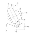
- FIG. FIG. 2 is a schematic side view of pulverizing rollers provided in the solid fuel pulverizing device according to the embodiment of the present disclosure
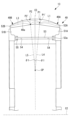
- FIG. 2 is a cross-sectional view of the essential parts of a pulverizing roller according to an embodiment of the present disclosure
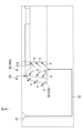
- 1 is a schematic illustration of a mold for manufacturing a crushing roller according to an embodiment of the present disclosure
- FIG. FIG. 5 is a schematic diagram showing a mold for manufacturing a crushing roller according to a modification of the embodiment of the present disclosure
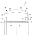
- FIG. 5 is a cross-sectional view of a main part of a crushing roller according to a modified example of the embodiment of the present disclosure
- FIG. 5 is a cross-sectional view of a main part of a crushing roller according to a modified example of the embodiment of the present disclosure
- FIG. 5 is a cross-sectional view of a main part of a crushing roller according to a modified example of the embodiment of the present disclosure
- FIG. 5 is a cross-sectional view of a main part of a crushing roller according to a modified example of the embodiment of the present disclosure
- a power plant 1 includes a solid fuel crusher 100 and a boiler 200 .
- “upper” means the vertically upper direction
- “upper” such as upper part or top surface means the vertically upper part.
- “lower” indicates the vertically lower part, and the vertical direction is not exact and includes errors.
- the solid fuel pulverizer 100 of the present embodiment is a device that pulverizes solid fuel such as biomass fuel and coal to generate pulverized fuel and supplies the pulverized fuel to the burner (combustion device) 220 of the boiler 200 .
- the solid fuel pulverization apparatus 100 of the present embodiment includes a mill (pulverization unit) 10, a bunker (storage unit) 21, a coal feeder (fuel supply unit) 25, a blower unit (carrier gas supply unit) 30, A state detection unit 40 and a control unit 50 are provided.
- the mill 10 for pulverizing solid fuel such as coal and biomass fuel to be supplied to the boiler 200 into pulverized fuel which is finely powdered solid fuel, may be of a type that pulverizes only coal or pulverizes only biomass fuel. Alternatively, it may be a form in which the biomass fuel is pulverized together with the coal.
- the biomass fuel is a renewable organic resource derived from living organisms. chips), etc., and are not limited to those presented here. Since biomass fuel takes in carbon dioxide during the growth process of biomass, it is considered to be carbon-neutral because it does not emit carbon dioxide that becomes a global warming gas.
- the mill 10 includes a housing 11, a grinding table 12, a grinding roller 13, a reduction gear (driving transmission section) 14, a mill motor (driving section) 15 connected to the reduction gear 14 for rotationally driving the grinding table 12, and a rotary A type classifier (classifying section) 16 , a coal feed pipe (fuel supply section) 17 , and a classifier motor 18 for rotating the rotary classifier 16 are provided.
- the housing 11 is a casing that is formed in a vertically extending cylindrical shape and houses the grinding table 12 , the grinding roller 13 , the rotary classifier 16 , and the coal feed pipe 17 .
- a coal feed pipe 17 is attached to the central portion of the ceiling portion 42 of the housing 11 .
- the coal feed pipe 17 supplies the solid fuel introduced from the bunker 21 through the coal feeder 25 into the housing 11, and is arranged in the center position of the housing 11 along the vertical direction. It extends to the inside of the housing 11 .
- a reduction gear 14 is installed in the vicinity of the bottom surface 41 of the housing 11, and a grinding table 12 is rotatably arranged to be rotated by driving force transmitted from a mill motor 15 connected to the reduction gear 14.
- the grinding table 12 is a circular member in plan view, and is arranged so that the lower ends of the coal feed pipes 17 face each other.
- the upper surface of the crushing table 12 may have, for example, a sloping shape in which the central portion is low and the outer peripheral portion is bent upward.
- the coal feed pipe 17 supplies solid fuel (for example, coal or biomass fuel in this embodiment) from above toward the crushing table 12 below, and the crushing table 12 feeds the supplied solid fuel between the crushing roller 13 and the crushing roller 13. Pinch and grind.
- the centrifugal force due to the rotation of the grinding table 12 guides the solid fuel to the outer peripheral side of the grinding table 12. It is sandwiched between the crushing rollers 13 and crushed.
- the pulverized solid fuel is blown upward by a carrier gas (hereinafter referred to as primary air) guided from a carrier gas flow path (hereinafter referred to as primary air flow path) 110 and rotated. It is led to the type classifier 16 .
- a blowout port (not shown) is provided on the outer periphery of the grinding table 12 to allow the primary air flowing from the primary air flow path 110 to flow out to the space above the grinding table 12 in the housing 11 .
- a swirl vane (not shown) is installed at the blowout port to give a swirling force to the primary air blown out from the blowout port.
- the primary air to which the swirl force is applied by the swirl vane becomes an air flow having a swirling velocity component, and the solid fuel pulverized on the pulverization table 12 is sent to the rotary classifier 16 located above in the housing 11. transport.
- those larger than a predetermined particle size are classified by the rotary classifier 16, or fall without reaching the rotary classifier 16 and are returned to the pulverization table 12. Then, it is pulverized again between the pulverizing table 12 and the pulverizing roller 13 .
- the crushing roller 13 is a rotating body that crushes the solid fuel supplied from the coal feed pipe 17 onto the crushing table 12 .
- the crushing roller 13 is pressed against the upper surface of the crushing table 12 and cooperates with the crushing table 12 to crush the solid fuel.
- only one crushing roller 13 is shown as a representative in FIG. .
- three crushing rollers 13 are equally spaced in the circumferential direction at angular intervals of 120° on the outer circumference. In this case, the portions where the three crushing rollers 13 come into contact with the upper surface of the crushing table 12 (the portions pressed) are equidistant from the rotation center axis of the crushing table 12 .
- the crushing roller 13 can be vertically swung and displaced by the journal head 43, and is supported on the upper surface of the crushing table 12 so that it can move toward and away from it.
- the crushing table 12 rotates while the outer peripheral surface is in contact with the solid fuel on the upper surface of the crushing table 12 , the crushing roller 13 receives a rotational force from the crushing table 12 and rotates with the crushing roller 13 .
- the solid fuel is supplied from the coal feed pipe 17, the solid fuel is pressed between the crushing roller 13 and the crushing table 12 and crushed. This pressing force is called crushing load.
- the support arm 44 of the journal head 43 is supported by a horizontal support shaft 45 at its intermediate portion so that the crushing roller 13 can be vertically swung and displaced about the support shaft 45 on the side surface of the housing 11 .
- a pressing device (pulverizing load imparting portion) 46 is provided at the upper end portion of the support arm 44 located vertically above.
- the pressing device 46 is fixed to the housing 11 and applies a crushing load to the crushing roller 13 via the support arm 44 and the like so as to press the crushing roller 13 against the crushing table 12 .
- the crushing load is applied, for example, by a hydraulic cylinder (not shown) operated by the pressure of hydraulic oil supplied from a hydraulic system (not shown) installed outside the mill 10 .
- the crushing load may be provided by the repulsive force of a spring (not shown).
- the speed reducer 14 is connected to the mill motor 15, transmits the driving force of the mill motor 15 to the grinding table 12, and rotates the grinding table 12 around the central axis.
- a rotary classifier (classifying section) 16 is provided in the upper portion of the housing 11 and has a hollow inverted conical outer shape.
- the rotary classifier 16 has a plurality of vertically extending blades 16a on its outer periphery.
- the blades 16a are provided at predetermined intervals (equal intervals) around the central axis of the rotary classifier 16.
- the rotary classifier 16 divides the solid fuel pulverized by the pulverization table 12 and the pulverization roller 13 (hereinafter, the pulverized solid fuel is referred to as "pulverized fuel" into a predetermined particle size (for example, 70 to 100 ⁇ m for coal).
- Classified into larger ones (hereinafter, pulverized fuel exceeding a predetermined particle size is referred to as "coarse fuel”) and those with a predetermined particle size or less (hereinafter, pulverized fuel with a predetermined particle size or less is referred to as “fine fuel”).
- coarse fuel pulverized fuel with a predetermined particle size or less.
- fine fuel pulverized fuel with a predetermined particle size or less.
- the rotary classifier 16 is driven by a classifier motor 18 controlled by a control unit 50, and rotates around the coal feed pipe 17 around a cylindrical shaft (not shown) extending in the vertical direction of the housing 11. to rotate.
- a fixed classifier having a fixed hollow inverted conical casing and a plurality of fixed swirl vanes instead of the blades 16a on the outer periphery of the casing may be used.
- the pulverized fuel reaching the rotary classifier 16 is knocked down by the blade 16a due to the relative balance between the centrifugal force generated by the rotation of the blade 16a and the centripetal force caused by the primary air flow. , is returned to the grinding table 12 for re-grinding, and the pulverized fuel is directed to the exit port 19 in the ceiling 42 of the housing 11 .
- the pulverized fuel classified by the rotary classifier 16 is discharged together with the primary air from the outlet port 19 to the pulverized fuel supply channel (pulverized fuel supply pipe) 120 and supplied to the burner 220 of the boiler 200 .
- the coal feed pipe (fuel supply portion) 17 is attached so that its lower end portion extends to the inside of the housing 11 along the vertical direction so as to penetrate the ceiling portion 42 of the housing 11 , and the coal feed pipe 17 is introduced from above.
- a solid fuel is supplied to the central portion of the grinding table 12 .
- a coal feeder 25 is connected to the upper end of the coal feed pipe 17 to supply solid fuel.
- the coal feeder 25 is connected to the bunker 21 by a downspout portion 22 which is a pipe extending vertically from the lower end of the bunker 21 .
- a valve (call gate, not shown) for switching the discharge state of the solid fuel from the bunker 21 may be provided in the middle of the down spout portion 22 .
- the coal feeder 25 includes a conveying unit 26 and a coal feeder motor 27 .
- the transport unit 26 is, for example, a belt conveyor, and transports the solid fuel discharged from the lower end of the down spout 22 to the upper part of the coal feed pipe 17 by the driving force of the coal feeder motor 27, and throws it inside.
- the amount of solid fuel supplied to the mill 10 is controlled by a signal from the control unit 50, for example, by adjusting the moving speed of the belt conveyor of the transport unit 26.
- the air blower 30 is a device that dries the pulverized fuel and blows primary air into the housing 11 for conveying it to the rotary classifier 16 .
- the air blower 30 includes a primary air fan (PAF) 31 and a hot gas flow path in order to appropriately adjust the flow rate and temperature of the primary air blown into the housing 11.
- PAF primary air fan
- 30a a cold gas channel 30b, a hot gas damper 30c and a cold gas damper 30d.
- the hot gas flow path 30a supplies part of the air sent from the primary air ventilator 31 as hot gas that has passed through the air preheater (heat exchanger) 34 and is heated.
- a hot gas damper 30c is provided in the hot gas flow path 30a.
- the opening degree of the hot gas damper 30c is controlled by the controller 50.
- FIG. The flow rate of the hot gas supplied from the hot gas flow path 30a is determined by the degree of opening of the hot gas damper 30c.
- the cold gas flow path 30b supplies part of the air sent from the primary air ventilator 31 as a normal temperature cold gas.
- a cold gas damper 30d is provided in the cold gas flow path 30b.
- the opening degree of the cold gas damper 30 d is controlled by the controller 50 .
- the flow rate of the cold gas supplied from the cold gas flow path 30b is determined by the degree of opening of the cold gas damper 30d.
- the flow rate of the primary air is the sum of the flow rate of the hot gas supplied from the hot gas channel 30a and the flow rate of the cold gas supplied from the cold gas channel 30b. It is determined by the mixing ratio of the hot gas supplied from the flow path 30 a and the cold gas supplied from the cold gas flow path 30 b and is controlled by the controller 50 .
- a part of the combustion gas discharged from the boiler 200 is introduced by a gas recirculation fan (not shown) into the hot gas supplied from the hot gas flow path 30a and mixed with the primary air flow path 110.
- the oxygen concentration in the primary air blown into the housing 11 from the air may be adjusted. By adjusting the oxygen concentration in the primary air, for example, when using a highly ignitable (easily ignitable) solid fuel, ignition of the solid fuel in the path from the mill 10 to the burner 220 is suppressed. can do.
- the state detection unit 40 of the present embodiment is, for example, differential pressure measuring means, and the pressure at the portion where the primary air flows into the housing 11 from the primary air flow path 110
- the differential pressure across the mill 10 is measured as the differential pressure between the primary air and the pressure at the outlet port 19 where the pulverized fuel is discharged.
- the increase/decrease in the differential pressure of the mill 10 corresponds to the increase/decrease in the amount of pulverized fuel circulating between the vicinity of the rotary classifier 16 inside the housing 11 and the vicinity of the grinding table 12 due to the classification effect of the rotary classifier 16. do.
- the state detection unit 40 of the present embodiment is, for example, temperature measuring means, and measures the temperature of the primary air supplied to the inside of the housing 11 (the temperature of the primary air at the mill inlet) and the temperature of the primary air and pulverized fuel at the outlet port 19 .
- the temperature of the mixed gas with (mill outlet primary air temperature) is detected, and the air blowing section 30 is controlled so as not to exceed the upper limit temperature of each.
- Each upper limit temperature is determined in consideration of the possibility of ignition depending on the properties of the solid fuel.
- the primary air temperature at the mill inlet is, for example, normal temperature to about 300 degrees
- the primary air temperature at the mill outlet is , for example, from room temperature to about 90 degrees.
- the controller 50 is a device that controls each part of the solid fuel crusher 100 .
- the control unit 50 may, for example, transmit a driving instruction to the mill motor 15 to control the rotation speed of the grinding table 12 .
- the control unit 50 transmits a drive instruction to the classifier motor 18 to control the rotation speed of the rotary classifier 16 to adjust the classification performance, and adjusts the particle size of the pulverized fuel according to the combustibility of the solid fuel in the burner 220.
- the amount of pulverized fuel corresponding to the amount of solid fuel supplied to the mill 10 can be stably supplied to the burner 220 while maintaining the amount of pulverized fuel within a range that does not affect the .
- control unit 50 can adjust the amount of solid fuel supplied to the mill 10 (coal supply amount) by, for example, transmitting a drive instruction to the coal feeder motor 27 . Further, the control unit 50 can control the opening degrees of the hot gas damper 30c and the cold gas damper 30d to adjust the flow rate and temperature of the primary air by transmitting the opening instruction to the air blowing unit 30 . Specifically, the control unit 50 controls the flow rate of the primary air supplied to the inside of the housing 11 and the temperature of the primary air at the outlet port 19 (the temperature of the primary air at the outlet port 19) for each type of solid fuel. The opening degrees of the hot gas damper 30c and the cold gas damper 30d are controlled so as to reach predetermined values set corresponding to the amounts. The temperature of the primary air may be controlled with respect to the temperature at the mill inlet (mill inlet primary air temperature).
- the control unit 50 is composed of, for example, a CPU (Central Processing Unit), a RAM (Random Access Memory), a ROM (Read Only Memory), and a computer-readable storage medium.
- a series of processes for realizing various functions are stored in a storage medium or the like in the form of a program, for example, and the CPU reads out this program to a RAM or the like, and executes information processing and arithmetic processing.
- the program may be pre-installed in a ROM or other storage medium, provided in a state stored in a computer-readable storage medium, or delivered via wired or wireless communication means. etc. may be applied.
- Computer-readable storage media include magnetic disks, magneto-optical disks, CD-ROMs, DVD-ROMs, semiconductor memories, and the like. Also, the HDD may be replaced with a solid state disk (SSD) or the like.
- Boiler 200 includes furnace 210 and burner 220 .
- the burner 220 heats a mixture of pulverized fuel and primary air supplied from the pulverized fuel supply pipe 120 and air (outside air) sent from a forced draft fan (FDF) 32 with an air preheater 34. It is a device that burns pulverized fuel and forms a flame using secondary air that is supplied as a secondary air.
- the pulverized fuel is burned in the furnace 210, and the high-temperature combustion gas is discharged outside the boiler 200 after passing through heat exchangers (not shown) such as an evaporator, superheater, and economizer.
- the combustion gas discharged from the boiler 200 is subjected to a predetermined treatment by an environmental device (a denitration device, a dust collector, a desulfurization device, etc., not shown), and is heat-exchanged with primary air and secondary air by the air preheater 34. is carried out, is led to a chimney (not shown) via an induced draft fan (IDF) 33, and is discharged to the outside air.
- an environmental device a denitration device, a dust collector, a desulfurization device, etc., not shown
- IDF induced draft fan
- the feed water to each heat exchanger of the boiler 200 is heated by an economizer (not shown) and then further heated by an evaporator (not shown) and a superheater (not shown) to generate high-temperature and high-pressure superheated steam. Then, it is sent to a steam turbine (not shown), which is a power generation unit, to rotate the steam turbine, and to rotate and drive a generator (not shown) connected to the steam turbine to generate power, forming the power plant 1. do.
- each crushing roller 13 is supported by the housing 11 via a journal shaft 47, a journal head 43, and a support shaft 45 so as to be rotatable about a rotation center axis C2.
- the journal shaft 47 extends downward from the vicinity of the side surface of the housing 11 toward the central portion of the housing 11 .
- the journal shaft 47 is fixed to the journal head 43 at its base end (the end on the side of the housing 11 ).
- the journal head 43 rotatably supports the crushing roller 13 at its tip (the end on the center side of the mill 10) via a bearing (not shown). That is, the crushing roller 13 is rotatably supported vertically above the crushing table 12 in an inclined state such that the upper part faces toward the center of the housing 11 rather than the lower part.
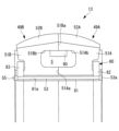
- the crushing roller 13 has a journal housing (supporting portion) 48 supported at the tip of the journal shaft 47 so as to be rotatable about the rotation center axis C2, and a circular housing 48 fitted to the journal housing 48. and an annular roller portion 49 .
- the journal housing 48 is provided so as to cover the tip of the journal shaft 47 and has a cylindrical outer peripheral surface.
- FIG. 3 shows a main part of a cross section of the roller portion 49 taken along a plane including the direction in which the rotation center axis C2 of the roller portion 49 extends (hereinafter referred to as an “axial cross section”).
- the roller portion 49 has a first portion 49A arranged on the base end side in the direction in which the rotation center axis C2 extends (hereinafter referred to as the “axial direction”), and a first portion 49A arranged along the axial direction. and a second portion 49B positioned at .
- the roller portion 49 is divided into two portions in the axial direction, the first portion 49A and the second portion 49B.
- the base end side is the side of the journal shaft 47 to which the crushing roller 13 is connected, and indicates the outer peripheral side (right side of the paper surface of FIG. 3) in the radial direction of the crushing table 12.
- the tip end side is the crushing table 12. 1) side (left side of the paper surface of FIG. 3) in the radial direction of .
- the first portion 49A and the second portion 49B are fixed with fixing bolts 53.
- the first portion 49A and the second portion 49B are arranged at different distances from the rotation center axis C1 of the grinding table 12, so they tend to rotate at different peripheral speeds. Therefore, a shearing force is generated on the joint surface between the first portion 49A and the second portion 49B, and the first portion 49A and the second portion 49B try to move relative to each other so as to slide.
- the joint surface wears due to sliding, so it is preferable that the first portion 49A and the second portion 49B be fixed so as to restrict relative movement.
- the roller portion 49 is formed uniformly in the circumferential direction. That is, the axial cross section has substantially the same structure at any position in the circumferential direction. Further, as shown in FIG. 3, the outer peripheral surface 49a of the roller portion 49 is curved in an arc shape centering on the center point CP in the axial cross section.
- the first portion 49A and the second portion 49B are symmetrical with respect to the center line C3. Therefore, the configuration of the first portion 49A will be described in detail below, and the configuration of the second portion 49B will be omitted unless necessary.
- the center line C3 is a line orthogonal to the rotation center axis C2 and passing through the central portion of the crushing roller 13 in the direction in which the rotation center axis C2 extends. In the present embodiment, the contact surface between the first portion 49A and the second portion 49B overlaps the center line C3.
- the first portion 49A partially includes a first base portion 51A made of high-chromium cast iron that fits into the journal housing 48, and a ceramic member provided on the outer peripheral surface of the first base portion 51A. It integrally has a first ceramic portion (peripheral portion) 52A. That is, the roller portion 49 according to the present embodiment is a so-called ceramic-embedded high-chromium cast iron roller.
- the first base portion 51A is supported by the journal housing 48. As shown in FIG. The first base portion 51A is formed in a substantially annular shape. Also, the first base portion 51A is fitted with the journal housing 48 so that the inner peripheral surface contacts the outer peripheral surface of the journal housing 48 .
- the first ceramic portion 52A is fixed to the outer peripheral portion of the annular first base portion 51A.
- the first ceramic portion 52A is provided over substantially the entire circumferential region of the first base portion 51A. That is, the first ceramic portion 52A is formed in a substantially annular shape. A bolt hole is formed through the first base portion 51A in the axial direction.
- the outer peripheral surface of the first base portion 51A is inclined in an axial cross section so as to approach the rotation center axis C2 as it goes from the center line C3 toward the base end portion in the axial direction.
- the inner peripheral surface of the first base portion 51A is a cylindrical surface.
- the surface of the first base portion 51A on the second portion 49B side (that is, the surface in contact with the second base portion 51B) is flat.
- the first ceramic portion 52A includes a ceramic member, it has a smaller coefficient of linear expansion than the first base portion 51A made of high-chromium cast iron. In addition, the first ceramic portion 52A is superior in wear resistance to the first base portion 51A.
- the materials of the first base portion 51A and the first ceramic portion 52A are not limited to the materials described above.
- the first ceramic portion 52A is formed in a substantially annular shape.
- the first ceramic portion 52A covers the entire outer peripheral surface of the first base portion 51A from the outside.
- the inner peripheral surface of the first ceramic portion 52A is in contact with the outer peripheral surface of the first base portion 51A.
- the outer peripheral surface of the first ceramic portion 52A is curved in an arc shape centering on the center point CP in the axial cross section.
- the surface of the first ceramic portion 52A on the side of the second portion 49B (that is, the surface in contact with the second ceramic portion 52B) is flat.
- the outer peripheral surface of the roller portion 49 is formed by the first ceramic portion 52A and the second ceramic portion 52B over the entire area in the axial direction.
- a fixing bolt 53 is inserted through a linear hole in which a bolt hole 54 formed in the first base portion 51A of the first portion 49A and a bolt hole 54 formed in the second base portion 51B of the second portion 49B communicate with each other. Fixed. A head portion 53a of the fixing bolt 53 is in contact with the first base portion 51A. A nut 55 screwed onto the tip of the fixing bolt 53 is in contact with the second base portion 51B. Therefore, by fastening the fixing bolt 53 and the nut 55, the first base portion 51A and the second base portion 51B are fixed. Thereby, the first portion 49A and the second portion 49B are joined.
- the fixing bolt 53 and the nut 55 may be a headless headless bolt and nuts at both ends.
- a dashed line L1 in FIGS. 2 and 3 indicates how the wear of the roller portion 49 progresses as the mill 10 pulverizes the solid fuel. That is, in the example of the present embodiment, the roller portion 49 has a portion P1 (hereinafter referred to as “maximum wear point P1”) on the base end side of the roller portion 49 (that is, the side opposite to the tip end side). It is in a situation where it is worn more than the part of As described above, the base end side indicates the outer peripheral side of the crushing table 12 in the radial direction, and the tip end side indicates the rotation center axis C1 (see FIG. 1) side of the crushing table 12 .
- a dashed line L2 in FIG. 2 indicates how the grinding table 12 wears.
- the maximum wear point P1 is located at the first ceramic portion 52A.
- the point of maximum wear before wear is indicated by symbol "P1”
- the point of maximum wear after actual wear progresses is indicated by symbol "P1'”.
- the maximum wear point P1 before wear is the point where wear is expected to progress most easily.
- the maximum wear point P1 is located on the outer peripheral surface 49a of the roller portion 49 with respect to the center line C3 (a line perpendicular to the rotation center axis C2 and passing through the center of the crushing roller 13 in the direction in which the rotation center axis C2 extends). is a position forming a predetermined angle .theta.1 toward the base end. Specifically, it is a position where a line L4 forming a predetermined angle ⁇ 1 between the center line C3 and the center point CP intersects with the outer peripheral surface 49a.
- the angle ⁇ 1 in FIG. 3 is set to 8 degrees as an example, the angle ⁇ 1 is not limited to 8 degrees.
- the position of the maximum wear point P1 varies, for example, depending on the specifications of the mill 10 and the solid fuel to be pulverized. There are many. Further, in the present embodiment, the thickness of the first ceramic portion 52A in the axial cross section is the thickest at the portion where the line L4 forming the predetermined angle ⁇ 1 with the center line C3 passes.
- the dashed line L3 in FIG. 3 indicates the case where the roller portion 49 is reversed and used after the roller portion 49 is worn as indicated by the dashed line L1 (that is, the roller portion 49 is once removed from the journal housing 48 and then 10 shows how the wear of the roller portion 49 progresses as the mill 10 pulverizes the solid fuel in the case where the roller portion 49 is attached to the journal housing 48 again by replacing the tip side with the tip side.
- the maximum wear point P2 in this case is a symmetrical position with respect to the center line C3. Specifically, the maximum wear point P2 is a point on L5, which is a line symmetrical to a line L4 forming a predetermined angle ⁇ 1 with the center line C3.
- the maximum wear point P2 at the time of reversal is located at the second ceramic portion 52B.
- the point of maximum wear before wear is indicated by "P2”
- the point of maximum wear after actual wear is indicated by "P2'”.
- the maximum wear point P2 before wear is the point where wear is expected to progress most easily.
- FIG. 3 shows a state in which the roller portion 49 is not reversed. Therefore, in a state in which the roller portion 49 is actually reversed, the second ceramic portion 52B is closer to the base end than the center line C3 ( 3). Therefore, the point of maximum wear P2 is also located on the proximal side (right side in FIG. 3) of the center line C3, like the point of maximum wear P1 before reversal.
- first the first portion 49A is manufactured.
- ceramic particles are shaped into a block shape (a shape corresponding to the first ceramic portion 52A), thereby forming a ceramic block CB (a portion of the first ceramic portion 52A). 4) is manufactured.
- a ceramic block is formed by bonding ceramic particles, and relatively many gaps are formed between the ceramic particles.
- the outer shape of the ceramic block CB is substantially the same as the outer shape of the first ceramic portion 52A.
- the manufactured ceramic block CB is installed at a predetermined position within the mold 60 .
- the ceramic block CB is fixed at a predetermined position by sandwiching the ceramic block CB between the ceiling surface and the bottom surface of the mold 60 .
- the ceramic block CB is sandwiched between the ceiling surface and the bottom surface of the casting mold 60, and is fixed at a predetermined position by buoyancy as will be described later during casting.
- the molten metal is poured into the mold 60 from the sprue 61 through the runner 62 . As a result, the mold 60 is filled with molten metal (see arrow m).
- the ceramic block CB since the ceramic block CB has a lower specific gravity than the molten metal, it is pressed against a predetermined position on the inner peripheral surface of the mold 60 by buoyancy (see arrow b), as shown in FIG. At this time, the molten metal also flows into the gaps formed between the ceramic particles of the ceramic block CB.
- the roller portion is integrated with the first ceramic portion 52A having excellent abrasion resistance in which the metal enters between the ceramic particles of the ceramic block CB and the first base portion 51A formed only of the solidified metal. 49 is completed.
- the first portion 49A of the present embodiment is manufactured by casting the first base portion 51A and the first ceramic portion 52A together.
- the bolt holes 54 may be provided by casting when the first portion 49A is cast. Since the first base portion 51A has high hardness, it is difficult to form the bolt holes 54 after solidification.
- the second portion 49B is manufactured. Since the method of manufacturing the second portion 49B is the same as the method of manufacturing the first portion 49A, the description thereof is omitted.
- the fixing bolts 53 and nuts 55 are tightened to join the first portion 49A and the second portion 49B.
- the roller portion 49 is manufactured.
- the first part 49A and the second part 49B are joined at the factory, and the roller part 49 in the joined state is transported to the site where the mill 10 is assembled. Cost can be reduced.
- the first portion 49A is provided on one side (base end side) of the axial center line C3, and the second portion 49B is provided on the other side (distal end side) of the axial center line C3.
- the ceramic portions 52 (the first ceramic portion 52A and the second ceramic portion 52B) having excellent wear resistance can be provided on both the one side and the other side of the roller portion 49 . Therefore, when the roller portion 49 is used by reversing it (that is, when the roller portion 49 is removed, the roller portion 49 is reversed so as to switch one side and the other side, and the roller portion 49 is attached again and used). Even if there is, the solid fuel can be pulverized between the ceramic portion 52 and the pulverizing table 12, so the abrasion of the roller portion 49 can be suppressed. Therefore, the life of the roller portion 49 can be lengthened.
- the roller portion 49 has a first portion 49A and a second portion 49B.
- the first portion 49A and the second portion 49B can be manufactured separately. Therefore, by fixing the separately manufactured first portion 49A and second portion 49B, the ceramic portion 52 (the first ceramic portion 52A and the second ceramic portion 52A and the second ceramic portion 52A) can be easily mounted on both sides in the axial direction. 52B) can be provided.
- the first portion 49A and the second portion 49B can be manufactured separately, the volume of parts manufactured at one time is reduced compared to the case where the first portion 49A and the second portion 49B are manufactured at once. can be reduced.
- the volume of the member manufactured by one casting can be reduced, so the amount of molten metal required for one casting can be reduced. can be reduced. Therefore, the size of the blast furnace for producing molten metal can be reduced. Therefore, it is possible to save the space of the facility for manufacturing the crushing roller 13 and reduce the initial cost of the facility.
- first portion 49A and the second portion 49B can be manufactured separately, even if a defect occurs during manufacturing of each portion, the entire roller portion 49 need not be discarded. amount can be reduced. Therefore, the yield in manufacturing the crushing roller 13 can be improved. Further, when remanufacturing the roller portion 49, if the portion to be discarded is remelted and reused, the cost for melting can be reduced.
- the amount of waste can be similarly reduced when manufacturing the ceramic block CB.
- FIG. UP in FIG. 5 indicates the upward direction in the vertical direction.
- This embodiment differs from the above embodiment in the method of manufacturing the second portion 49B and the method of joining the first portion 49A and the second portion 49B. Since other configurations and the like are the same as those of the above embodiment, the same configurations and the like are denoted by the same reference numerals, and detailed description thereof will be omitted.
- the first portion 49A and the second portion 49B are joined by casting and integrated. Specifically, the completed first portion 49A is placed in the mold 160 at the bottom. At this time, the first portion 49A is sufficiently preheated. When the first portion 49A is placed in the mold 160 and then molten metal is introduced, the first portion 49A acts like a chill during casting, cooling and shrinking the molten metal. There is a possibility that shrinkage cavities may be generated inside the second portion 49B. By preheating the first portion 49A, the degree of cooling of the molten metal is reduced, so the occurrence of shrinkage cavities can be suppressed.
- the manufacturing method of the first portion 49A is the same as that of the above embodiment.
- the manufactured ceramic block CB for the second portion 49B is placed at a predetermined position within the mold 160.
- the ceramic block CB is fixed at a predetermined position by sandwiching the ceramic block CB between the ceiling surface of the mold 160 and the first portion 49A (the first ceramic portion 52A).
- the molten metal is poured into the mold 160 from the sprue 61 through the runner 62 .
- the molten metal is poured into the space above the first portion 49A.
- the mold 160 is filled with molten metal (see arrow m).
- the molten metal is then cooled and solidified. Thereby, the second portion 49B is manufactured. At this time, the second portion 49B is manufactured in a state of being joined and integrated with the first portion 49A. In this modification, the roller portion 49 is manufactured in this manner.
- the second portion 49B has a shape corresponding to the joint surface of the first portion 49A. no need to apply. Therefore, the machining process can be omitted.
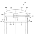
- the first portion 49A may have a protruding portion 70 having a substantially T-shaped cross section.
- the protruding portion 70 protrudes from the surface of the first base portion 51A on the second portion 49B side.
- the projecting portion 70 is formed so as to be integrated with the first base portion 51A when casting the first portion 49A. With this configuration, when the second portion 49B is manufactured, the protruding portion 70 is embedded in the second portion 49B, so that the first portion 49A and the second portion 49B are joined more firmly. be able to.
- the first portion 49A and the second portion 49B are joined by casting. Therefore, the roller portion 49 is not provided with the fixing bolt 53 and the nut 55 described in the above embodiment. No bolt holes 54 are formed in the first base portion 51A and the second base portion 51B.
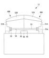
- the fixing portion 80 is used to join the first portion 49A and the second portion 49B.
- the fixed portion 80 includes a cylindrical portion 81 provided between the journal housing 48 and the first base portion 51A and the second base portion 51B, and a first base portion 81 extending radially outward from one end portion of the cylindrical portion 81 in the axial direction.
- a first contact portion 82 that contacts one axial end surface of the base portion 51A, and a first contact portion 82 that extends radially outward from the other axial end portion of the cylindrical portion 81 and the other axial side of the second base portion 51B.
- a second abutment portion 83 that abuts on the end surface of the .
- the fixed portion 80 is made of a material (for example, carbon steel) that has a hardness lower than that of the first base portion 51A and the second base portion 51B and that can be easily machined.
- the cylindrical portion 81 is formed with a bolt hole 81a through which the fixing bolt 53 is inserted.
- the first base portion 51A is fitted to the outer peripheral portion of the journal housing 48 via the cylindrical portion 81 from the outside.
- the second base portion 51B is fitted to the outer peripheral portion of the journal housing 48 via the cylindrical portion 81 from the outside.
- the first contact portion 82 and the second contact portion 83 are fixed by a fixing bolt 53 inserted through the cylindrical portion 81 .
- a head portion 53 a of the fixing bolt 53 is in contact with the first contact portion 82 .
- a nut 55 screwed onto the tip of the fixing bolt 53 is in contact with the second contact portion 83 . Therefore, by fastening the fixing bolt 53 and the nut 55, the first contact portion 82 and the second contact portion 83 sandwich the first base portion 51A and the second base portion 51B from both sides in the axial direction. become. Therefore, the first portion 49A and the second portion 49B can be joined.
- the fixing portion 80 has a lower hardness than the first base portion 51A and the like, it can be easily machined. This makes it possible to easily insert the fixing bolt 53 in comparison with the case where the bolt hole 81a is formed in the first base portion 51A or the like. Therefore, the crushing roller 13 can be manufactured easily.
- the fixing portion 80 is used to join the first portion 49A and the second portion 49B. Therefore, the roller portion 49 is not provided with the fixing bolt 53 and the nut 55 described in the above embodiment. No bolt holes 54 are formed in the first base portion 51A and the second base portion 51B.
- the first base portion 51A has a first recessed portion 51Ab that is recessed from the first contact surface 51Aa that contacts the second base portion 51B.
- the second base portion 51B has a second recessed portion 51Bb that is recessed from the second contact surface 51Ba that contacts the first base portion 51A.
- first recessed portion 51Ab and the second recessed portion 51Bb form a closed space S.
- the first base portion 51A and the second base portion 51B have recesses.
- the volumes of the first base portion 51A and the second base portion 51B can be reduced compared to a configuration having no concave portion.
- a detection unit 90 that detects wear of the first ceramic portion 52A and the second ceramic portion 52B may be provided in the closed space S formed by the first recess 51Ab and the second recess 51Bb. Thereby, wear of the first ceramic portion 52A and the second ceramic portion 52B can be detected. Further, by providing the detection unit 90 in the concave portions formed in the first base portion 51A and the second base portion 51B, the detection portion 90 and the detection targets of the detection portion 90 (in this modification, the first ceramic portion 52A and the second The distance to the ceramic portion 52B) can be made relatively short. Therefore, the structure of the wear detecting means can be simplified.
- the detection unit 90 is provided in the closed space S, it is difficult for the pulverized solid fuel or the like to come into contact with the detection unit 90 . Therefore, it is possible to make the detection unit 90 less likely to be damaged.
- a method of detecting wear by the detection unit 90 an electrical method using a probe, a method using sound waves, or the like is used.
- the suspension piece 91 is sandwiched between the joint surfaces of the first portion 49A and the second portion 49B.
- An eyebolt 92 is engaged with the suspension piece 91 .
- the crushing roller 13 is provided with hanging bolt holes that are used when the mill 10 is installed or maintained.
- Suspension bolt holes may be integrated by casting a carbon suspension piece, which is easy to process, into the roller portion 49 . At the time of casting, there is a possibility that part of the suspension piece is melted and the molten metal of the suspension piece is mixed into the metal structure of the base of the roller portion 49 .
- the suspension piece 91 since the suspension piece 91 is sandwiched between the joint surfaces of the first portion 49A and the second portion 49B, it is possible to suppress contamination of dissimilar metals during casting.
- the journal housing 48 has an engagement projection 96 that engages with the engagement recess 95 .
- the engaging concave portion 95 and the engaging convex portion 96 are engaged with each other, thereby restricting the relative movement between the journal housing 48 and the first base portion 51A and the second base portion 51B.
- the journal housing 48, the first base portion 51A and the second base portion 51B can be firmly fixed.
- the engaging convex portion 96 is accommodated within the engaging concave portion 95 .
- the pulverized solid fuel or the like is less likely to come into contact with the engaging projections 96 compared to the case where the engaging portion between the roller portion 49 and the journal housing 48 is provided at the axial end portion of the crushing roller 13 . Therefore, it is possible to make the engaging convex portion 96 less likely to be worn.
- the engagement protrusion 96 may be detachable from the journal housing 48 so that the crushing roller 13 can be attached to the journal housing 48 from only one side. Specifically, the first portion 49A may be installed on the journal housing 48 first, then the engaging protrusion 96 may be installed, and then the second portion 49B may be installed and coupled.
- the axial length of the crushing roller 13 can be increased while maintaining the width of the crushing surface. can be shortened, the crushing surface of the crushing roller 13 can be placed further outside the crushing table 12 even on the crushing table 12 having the same diameter. Therefore, while suppressing an increase in the outer diameter of the housing 11 that accommodates these crushing parts, a crushing part of a size close to that of a larger mill can be realized, and a compact and large-capacity mill can be realized.
- the present disclosure is not limited to the above-described embodiments, and modifications can be made as appropriate without departing from the scope of the present disclosure.
- the solid fuel used is not limited to the present disclosure, and coal, biomass fuel, petroleum coke (PC), etc. can be used. Additionally, a combination of these solid fuels may be used. Also, for example, if only one of the first portion 49A or the second portion 49B is worn or damaged, only one of the first portion 49A or the second portion 49B may be replaced. As a result, the material cost of the maintenance cost for the crushing roller 13 can be halved.
- a structure that prevents the entry of finely divided fuel may be provided on the joint surfaces of the first portion 49A and the second portion 49B, for example, by applying or filling a liquid gasket or a paste sealant.
- a crushing roller according to an aspect of the present disclosure is housed inside a housing (11) and crushes solid fuel by sandwiching the solid fuel between itself and a rotating crushing table (12).
- a crushing roller (13) that rotates with the rotational force of a support (48) that is rotatably supported with respect to the housing (11) about a central axis (C2); an annular roller portion (49) that is fitted to the outer peripheral portion of (48) from the outside and crushes the solid fuel between the crushing table (12), the roller portion (49)
- the first part (49A) is arranged side by side with the first part (49A) along the axial direction, which is the direction in which the rotation center axis (C2) of the roller part (49) extends, and the first part ( 49A), and the first portion (49A) has a first base portion (51A) fitted to the outer peripheral portion of the support portion (48) from the outside.
- the second portion (49B) includes a second base portion (51B) fitted to the outer peripheral portion of the support portion (48) from the outside, and the second base portion (51B). and a second outer peripheral portion (52A) that is provided on the outer peripheral surface of the second base portion (51B) and has better wear resistance than the second base portion (51B), and is provided on the other side of the center line (C3) in the axial direction It is
- the first portion is provided on one side of the axial centerline
- the second portion is provided on the other side of the axial centerline.
- outer peripheral portions first outer peripheral portion and second outer peripheral portion
- wear resistance can be provided on both one side and the other side of the roller portion. Therefore, even when the roller part is used by reversing it (that is, when the roller part is removed, the roller part is reversed so that one side and the other side are exchanged, and the roller part is attached again and used), Since the solid fuel can be pulverized by the outer peripheral portion, wear of the roller portion can be suppressed. Therefore, the life of the roller portion can be lengthened. Further, in the above configuration, the roller portion has the first portion and the second portion.
- first part and the second part can be manufactured separately. Therefore, by fixing the separately manufactured first portion and second portion, it is possible to easily provide outer peripheral portions on both sides in the axial direction.
- first part and the second part can be manufactured separately, the volume of parts to be manufactured at one time can be reduced compared to the case where the first part and the second part are manufactured at once. can be done.
- the volume of the member manufactured by one casting can be reduced, so the amount of molten metal required for one casting is can be reduced. Therefore, the size of the blast furnace for producing molten metal can be reduced.
- the first portion and the second portion can be manufactured separately, even if a defect occurs during the manufacturing of each portion, the entire roller portion does not need to be scrapped, reducing the amount of scrap. can do. Therefore, it is possible to improve the yield in manufacturing the crushing roller. Moreover, when dissolving the portion to be discarded in order to manufacture the roller portion again, the cost for dissolving can be reduced.
- the roller portion (49) is a cylindrical roller provided between the support portion (48) and the first base portion (51A) and the second base portion (51B). a portion (81) extending radially and outwardly from one end of the cylindrical portion (81) in the axial direction (C2) and one side of the first base portion (51A) in the axial direction (C2); and a first contact portion (82) that contacts the end surface of the second base (51B), extending radially outward from the other end of the cylindrical portion (81) in the axial direction (C2). and a second contact portion (83) contacting the other end face in the axial direction (C2).
- the second base portion (51B) is fitted to the outer peripheral portion of the support portion (48) from the outside through the cylindrical portion (81).
- the first contact portion (82) and the second contact portion (83) are fixed by bolts (53) that pass through the fixing portion (80), and the cylindrical portion (81) is made of a material having hardness lower than that of the first base (51A) and the second base (51B).
- the first contact portion and the second contact portion are fixed by bolts that pass through the fixing portion.
- the first contact portion and the second contact portion sandwich the first base portion and the second base portion from both sides in the axial direction. Therefore, the first part and the second part can be fixed.
- the cylindrical portion has a lower hardness than the base portion, it can be easily machined. As a result, the bolt can be inserted more easily than when a bolt hole through which the bolt is inserted is formed in the base. Therefore, the crushing roller can be manufactured easily.
- the first portion (49A) and the second portion (49B) are formed in a hole formed in the first base portion (51A) and in the second base portion (52B). It is fixed by a fastener (53) inserted through a straight bolt hole (54) communicating with the formed hole.
- the first part and the second part are fixed only by the fastener.
- the first part and the second part can be fixed without using a large-scale part (for example, a part for fixing the first part and the second part by sandwiching them from the outside). Therefore, the structure can be simplified.
- the first base portion (51A) has a first contact surface (51Aa) that contacts the second base portion (51B) and the first contact surface (51Aa).
- the second base portion (51B) has a second contact surface (51Ba) that contacts the first contact surface (51Aa) of the first base portion (51A). and a second recess (51Bb) recessed from the second contact surface (51Ba).
- the first base and the second base have recesses. This makes it possible to reduce the volumes of the first base and the second base compared to a configuration that does not have recesses.
- the volume of the member manufactured by one casting can be reduced, so the amount of molten metal required for one casting is can be reduced. Therefore, the size of the blast furnace for producing molten metal can be reduced. Therefore, it is possible to save the space of the equipment for manufacturing the crushing roller, and to reduce the initial cost of the equipment.
- the first recess (51Ab) and the second recess (51Bb) form a closed space, and the closed space includes the first outer peripheral portion (52A) and / Or a detection part (90) for detecting wear of the second outer peripheral part is provided.
- the closed space formed by the first recess and the second recess is provided, the volumes of the first base and the second base can be reduced. Thereby, when manufacturing the first part and the second part, the amount of molten metal required for one casting can be reduced. Therefore, the size of the blast furnace for producing molten metal can be reduced. Therefore, it is possible to save the space of the equipment for manufacturing the crushing roller, and to reduce the initial cost of the equipment.
- a detection unit that detects wear of the first outer peripheral portion and/or the second outer peripheral portion is provided in the closed space formed by the first recess and the second recess. Thereby, wear of the first outer peripheral portion and/or the second outer peripheral portion can be detected.
- the detection section in the concave portion formed in the base, the distance between the detection section and the object (the first outer circumference and/or the second outer circumference) to be detected by the detection section can be relatively shortened. can. Therefore, the structure of the wear detecting means can be simplified. Further, since the detection section is provided in the closed space, pulverized solid fuel or the like is less likely to come into contact with the detection section. Therefore, it is possible to make the detection unit less likely to be damaged.
- the first base portion (51A) and/or the second base portion (51B) has an engagement concave portion (95) recessed from a surface in contact with the support portion (48). and the support portion (48) is housed in the engagement recess (95) on the surface that contacts the first base portion (51A) and/or the second base portion (51B). It has an engagement projection (96) that engages with the engagement recess (95).
- the supporting portion has the engaging convex portion that engages with the engaging concave portion. Accordingly, the engaging concave portion and the engaging convex portion are engaged with each other, thereby restricting the relative movement between the support portion and the first base portion and/or the second base portion. Thereby, the support portion and the first base portion and/or the second base portion can be firmly fixed. Also, the engaging projection is accommodated in the engaging recess. As a result, pulverized solid fuel or the like is less likely to come into contact with the engaging projections, compared to the case where the engagement portion between the roller portion and the journal housing is provided at the axial end portion of the crushing roller. Therefore, it is possible to make it difficult to damage the engaging protrusions.
- a solid fuel pulverizing device includes any one of the pulverizing rollers (13) described above and the pulverizing roller (13), which rotates and sandwiches the solid fuel between the pulverizing roller (13) to pulverize the solid fuel. and a housing (11) that accommodates the crushing roller (13) and the crushing table (12).
- a method for manufacturing a crushing roller includes a crushing table (12) that is housed inside a housing (11) and crushes the solid fuel by sandwiching the solid fuel between itself and a crushing table (12) that rotates.
- a method for manufacturing a crushing roller (13) that rotates with a rotational force from a table (12), wherein the crushing roller (13) rotates with respect to the housing (11) about a central axis (C2).
- a support portion (48) that is rotatably supported, and an annular roller portion ( 49), wherein the roller portion (49) extends along the first portion (49A) and the axial direction along which the rotation center axis (C2) of the roller portion (49) extends.
- a second portion (49B) arranged side by side with the first portion (49A) and secured to the first portion (49A), the first portion (49A) being attached to the support portion (48);
- a first base portion (51A) fitted to the outer peripheral portion from the outside, and a first outer peripheral portion provided on the outer peripheral surface of the first base portion (51A) and having a wear resistance superior to that of the first base portion (51A).
- the step of manufacturing the second portion (49B) and the step of fixing the first portion (49A) and the second portion (49B) include: The first part manufactured in the step of manufacturing the first part is placed in a mold (160) having a shape corresponding to the crushing roller, and molten metal is poured into the mold (160) and melted. By cooling the metal, the second part (49B) is manufactured and the first part (49A) and the second part (49B) are integrally fixed.
- the second portion since the second portion has a shape corresponding to the joint surface of the first portion, it is not necessary to machine the joint surface of the first portion and the joint surface of the second portion. Therefore, the machining process can be omitted.
- the first portion (49A) has a protruding portion (70) protruding from the surface on the second portion (51B) side.
- the projecting portion is embedded in the second portion, so the first portion and the second portion can be joined more firmly.
Landscapes
- Engineering & Computer Science (AREA)
- Food Science & Technology (AREA)
- Crushing And Grinding (AREA)
Priority Applications (4)
| Application Number | Priority Date | Filing Date | Title |
|---|---|---|---|
| EP26152888.9A EP4706828A3 (en) | 2021-12-22 | 2022-11-30 | Crushing roller, solid fuel crushing device, and method for producing crushing roller |
| CN202280083410.XA CN118354848B (zh) | 2021-12-22 | 2022-11-30 | 粉碎辊及固体燃料粉碎装置以及粉碎辊的制造方法 |
| EP26152893.9A EP4706829A3 (en) | 2021-12-22 | 2022-11-30 | Crushing roller, solid fuel crushing device, and method for producing crushing roller |
| EP22910800.6A EP4434634A4 (en) | 2021-12-22 | 2022-11-30 | CRUSHING ROLLER, SOLID FUEL CRUSHING DEVICE AND METHOD FOR PRODUCING A CRUSHING ROLLER |
Applications Claiming Priority (2)
| Application Number | Priority Date | Filing Date | Title |
|---|---|---|---|
| JP2021-208066 | 2021-12-22 | ||
| JP2021208066A JP7818954B2 (ja) | 2021-12-22 | 2021-12-22 | 粉砕ローラ及び固体燃料粉砕装置並びに粉砕ローラの製造方法 |
Publications (1)
| Publication Number | Publication Date |
|---|---|
| WO2023120083A1 true WO2023120083A1 (ja) | 2023-06-29 |
Family
ID=86902079
Family Applications (1)
| Application Number | Title | Priority Date | Filing Date |
|---|---|---|---|
| PCT/JP2022/044274 Ceased WO2023120083A1 (ja) | 2021-12-22 | 2022-11-30 | 粉砕ローラ及び固体燃料粉砕装置並びに粉砕ローラの製造方法 |
Country Status (4)
| Country | Link |
|---|---|
| EP (3) | EP4706829A3 (cg-RX-API-DMAC7.html) |
| JP (1) | JP7818954B2 (cg-RX-API-DMAC7.html) |
| CN (1) | CN118354848B (cg-RX-API-DMAC7.html) |
| WO (1) | WO2023120083A1 (cg-RX-API-DMAC7.html) |
Families Citing this family (1)
| Publication number | Priority date | Publication date | Assignee | Title |
|---|---|---|---|---|
| JP2024067390A (ja) * | 2022-11-04 | 2024-05-17 | 三菱重工業株式会社 | 粉砕ローラ、粉砕テーブル及び固体燃料粉砕装置並びに粉砕ローラの製造方法 |
Citations (7)
| Publication number | Priority date | Publication date | Assignee | Title |
|---|---|---|---|---|
| JPS59184942U (ja) * | 1983-05-24 | 1984-12-08 | 石川島播磨重工業株式会社 | 竪型ミル用ロ−ラタイヤの固定装置 |
| JPS62204862A (ja) | 1986-03-05 | 1987-09-09 | 川崎重工業株式会社 | 竪型ミルのロ−ラ装置 |
| JPH04106632U (ja) * | 1991-02-22 | 1992-09-14 | 宇部興産株式会社 | 竪型粉砕機 |
| JP2003190825A (ja) * | 2001-12-28 | 2003-07-08 | Ishikawajima Harima Heavy Ind Co Ltd | 竪型ミル |
| JP2016179428A (ja) * | 2015-03-24 | 2016-10-13 | 宇部興産機械株式会社 | 竪型粉砕機の粉砕ローラ |
| JP2020011164A (ja) | 2018-07-13 | 2020-01-23 | 三菱日立パワーシステムズ株式会社 | 粉砕ローラの製造方法及び昇温装置 |
| JP2021130087A (ja) * | 2020-02-19 | 2021-09-09 | 三菱パワー株式会社 | ローラミル装置及びローラミル装置の改造方法 |
Family Cites Families (11)
| Publication number | Priority date | Publication date | Assignee | Title |
|---|---|---|---|---|
| US1480767A (en) * | 1924-01-15 | Pulverizer | ||
| SU1053875A1 (ru) * | 1981-11-18 | 1983-11-15 | Сызранский турбостроительный завод | Бандаж размольного валка среднеходной мельницы |
| JPH0757367B2 (ja) * | 1988-10-14 | 1995-06-21 | 株式会社日立製作所 | セラミックスリーブ組立式圧延ロール |
| JPH04102646U (ja) * | 1991-02-14 | 1992-09-04 | 磯部鉄工株式会社 | 粉砕ミルのタイヤ |
| JP2563631Y2 (ja) * | 1991-09-27 | 1998-02-25 | 株式会社神戸製鋼所 | ローラミル |
| JPH06226129A (ja) * | 1993-02-05 | 1994-08-16 | Babcock Hitachi Kk | 粉砕装置 |
| CN103596692B (zh) * | 2011-09-30 | 2015-09-23 | 三菱重工业株式会社 | 生物质粉碎装置及生物质/煤混烧系统 |
| EP3171980B1 (en) * | 2014-07-25 | 2018-08-29 | FLSmidth A/S | A roller with a segmented wear surface for crushing particulate material |
| JP6578110B2 (ja) * | 2015-03-05 | 2019-09-18 | 三菱日立パワーシステムズ株式会社 | 粉砕ローラ及び粉砕機 |
| JP5859698B1 (ja) * | 2015-04-17 | 2016-02-10 | 三菱日立パワーシステムズ株式会社 | 粉砕ローラ及び粉砕装置 |
| EP3308861A1 (fr) * | 2016-10-12 | 2018-04-18 | Magotteaux International S.A. | Galet de broyage |
-
2021
- 2021-12-22 JP JP2021208066A patent/JP7818954B2/ja active Active
-
2022
- 2022-11-30 EP EP26152893.9A patent/EP4706829A3/en active Pending
- 2022-11-30 EP EP22910800.6A patent/EP4434634A4/en active Pending
- 2022-11-30 WO PCT/JP2022/044274 patent/WO2023120083A1/ja not_active Ceased
- 2022-11-30 EP EP26152888.9A patent/EP4706828A3/en active Pending
- 2022-11-30 CN CN202280083410.XA patent/CN118354848B/zh active Active
Patent Citations (7)
| Publication number | Priority date | Publication date | Assignee | Title |
|---|---|---|---|---|
| JPS59184942U (ja) * | 1983-05-24 | 1984-12-08 | 石川島播磨重工業株式会社 | 竪型ミル用ロ−ラタイヤの固定装置 |
| JPS62204862A (ja) | 1986-03-05 | 1987-09-09 | 川崎重工業株式会社 | 竪型ミルのロ−ラ装置 |
| JPH04106632U (ja) * | 1991-02-22 | 1992-09-14 | 宇部興産株式会社 | 竪型粉砕機 |
| JP2003190825A (ja) * | 2001-12-28 | 2003-07-08 | Ishikawajima Harima Heavy Ind Co Ltd | 竪型ミル |
| JP2016179428A (ja) * | 2015-03-24 | 2016-10-13 | 宇部興産機械株式会社 | 竪型粉砕機の粉砕ローラ |
| JP2020011164A (ja) | 2018-07-13 | 2020-01-23 | 三菱日立パワーシステムズ株式会社 | 粉砕ローラの製造方法及び昇温装置 |
| JP2021130087A (ja) * | 2020-02-19 | 2021-09-09 | 三菱パワー株式会社 | ローラミル装置及びローラミル装置の改造方法 |
Non-Patent Citations (1)
| Title |
|---|
| See also references of EP4434634A4 |
Also Published As
| Publication number | Publication date |
|---|---|
| EP4434634A4 (en) | 2024-11-27 |
| CN118354848A (zh) | 2024-07-16 |
| JP2023092829A (ja) | 2023-07-04 |
| JP7818954B2 (ja) | 2026-02-24 |
| EP4706829A3 (en) | 2026-05-27 |
| CN118354848B (zh) | 2026-06-05 |
| EP4706828A2 (en) | 2026-03-11 |
| EP4434634A1 (en) | 2024-09-25 |
| EP4706829A2 (en) | 2026-03-11 |
| EP4706828A3 (en) | 2026-05-27 |
Similar Documents
| Publication | Publication Date | Title |
|---|---|---|
| WO2020158270A1 (ja) | 粉砕機及びボイラシステム並びに粉砕機の運転方法 | |
| JP7818954B2 (ja) | 粉砕ローラ及び固体燃料粉砕装置並びに粉砕ローラの製造方法 | |
| JP2021067408A (ja) | 安定運転制御システム及び固体燃料粉砕装置、並びに安定運転制御方法、並びに安定運転制御プログラム | |
| JP7693365B2 (ja) | 分級機及び発電プラント並びに分級機の運転方法 | |
| WO2020045276A1 (ja) | 固体燃料粉砕装置及びこれを備えた発電プラント並びに固体燃料粉砕方法 | |
| WO2023120079A1 (ja) | 粉砕ローラ及び固体燃料粉砕装置並びに粉砕ローラの製造方法 | |
| WO2023112683A1 (ja) | 粉砕ローラ及び固体燃料粉砕装置並びに粉砕ローラの製造方法 | |
| JP7665320B2 (ja) | 粉砕機及び発電プラント並びに粉砕機の運転方法 | |
| JP7797240B2 (ja) | ローラジャーナルプロテクタ及び取外し方法 | |
| TWI884777B (zh) | 分級機及粉碎機,以及分級機之製造方法 | |
| WO2024095875A1 (ja) | 粉砕ローラ、粉砕テーブル及び固体燃料粉砕装置並びに粉砕ローラの製造方法 | |
| WO2024096063A1 (ja) | 粉砕ローラ、粉砕テーブル及び固体燃料粉砕装置並びに粉砕ローラの製造方法 | |
| WO2024095874A1 (ja) | 粉砕ローラ、粉砕テーブル及び固体燃料粉砕装置並びに粉砕ローラの製造方法 | |
| JP7612396B2 (ja) | 粉砕機及び発電プラント並びに粉砕機の運転方法 | |
| JP2025154299A (ja) | 粉砕テーブル及び固体燃料粉砕装置並びに粉砕テーブルの補修方法 | |
| WO2025182266A1 (ja) | 弁装置及び固体燃料粉砕装置並びに弁装置の運転方法 | |
| WO2020045129A1 (ja) | 固体燃料粉砕装置及びこれを備えた発電プラント並びに固体燃料粉砕の制御方法 | |
| JP7703337B2 (ja) | ロータリバルブ、供給装置及び発電プラント並びにロータリバルブの運転方法 | |
| JP7592515B2 (ja) | 固体燃料供給設備及び発電プラント並びに固体燃料の供給方法 | |
| JP3655347B2 (ja) | ローラミル | |
| JP2024082964A (ja) | 回転体支持構造、分級機及び固体燃料粉砕装置並びに回転体支持方法 | |
| JP2024145457A (ja) | 燃料供給装置の保護システム、固体燃料粉砕装置、ボイラシステム及び燃料供給装置を保護する方法 | |
| JPH06226129A (ja) | 粉砕装置 |
Legal Events
| Date | Code | Title | Description |
|---|---|---|---|
| 121 | Ep: the epo has been informed by wipo that ep was designated in this application |
Ref document number: 22910800 Country of ref document: EP Kind code of ref document: A1 |
|
| WWE | Wipo information: entry into national phase |
Ref document number: 202280083410.X Country of ref document: CN Ref document number: 2022910800 Country of ref document: EP |
|
| WWE | Wipo information: entry into national phase |
Ref document number: 202417047629 Country of ref document: IN |
|
| ENP | Entry into the national phase |
Ref document number: 2022910800 Country of ref document: EP Effective date: 20240617 |
|
| NENP | Non-entry into the national phase |
Ref country code: DE |