WO2023120004A1 - 電子制御装置及び電動ブレーキ装置 - Google Patents
電子制御装置及び電動ブレーキ装置 Download PDFInfo
- Publication number
- WO2023120004A1 WO2023120004A1 PCT/JP2022/043130 JP2022043130W WO2023120004A1 WO 2023120004 A1 WO2023120004 A1 WO 2023120004A1 JP 2022043130 W JP2022043130 W JP 2022043130W WO 2023120004 A1 WO2023120004 A1 WO 2023120004A1
- Authority
- WO
- WIPO (PCT)
- Prior art keywords
- substrate
- contact portion
- control device
- heat
- electronic component
- Prior art date
- Legal status (The legal status is an assumption and is not a legal conclusion. Google has not performed a legal analysis and makes no representation as to the accuracy of the status listed.)
- Ceased
Links
Images




Classifications
-
- H—ELECTRICITY
- H05—ELECTRIC TECHNIQUES NOT OTHERWISE PROVIDED FOR
- H05K—PRINTED CIRCUITS; CASINGS OR CONSTRUCTIONAL DETAILS OF ELECTRIC APPARATUS; MANUFACTURE OF ASSEMBLAGES OF ELECTRICAL COMPONENTS
- H05K7/00—Constructional details common to different types of electric apparatus
- H05K7/20—Modifications to facilitate cooling, ventilating, or heating
- H05K7/2089—Modifications to facilitate cooling, ventilating, or heating for power electronics, e.g. for inverters for controlling motor
- H05K7/209—Heat transfer by conduction from internal heat source to heat radiating structure
-
- H—ELECTRICITY
- H05—ELECTRIC TECHNIQUES NOT OTHERWISE PROVIDED FOR
- H05K—PRINTED CIRCUITS; CASINGS OR CONSTRUCTIONAL DETAILS OF ELECTRIC APPARATUS; MANUFACTURE OF ASSEMBLAGES OF ELECTRICAL COMPONENTS
- H05K7/00—Constructional details common to different types of electric apparatus
- H05K7/20—Modifications to facilitate cooling, ventilating, or heating
- H05K7/2039—Modifications to facilitate cooling, ventilating, or heating characterised by the heat transfer by conduction from the heat generating element to a dissipating body
- H05K7/20509—Multiple-component heat spreaders; Multi-component heat-conducting support plates; Multi-component non-closed heat-conducting structures
-
- H—ELECTRICITY
- H02—GENERATION; CONVERSION OR DISTRIBUTION OF ELECTRIC POWER
- H02K—DYNAMO-ELECTRIC MACHINES
- H02K5/00—Casings; Enclosures; Supports
- H02K5/04—Casings or enclosures characterised by the shape, form or construction thereof
- H02K5/22—Auxiliary parts of casings not covered by groups H02K5/06-H02K5/20, e.g. shaped to form connection boxes or terminal boxes
-
- B—PERFORMING OPERATIONS; TRANSPORTING
- B60—VEHICLES IN GENERAL
- B60T—VEHICLE BRAKE CONTROL SYSTEMS OR PARTS THEREOF; BRAKE CONTROL SYSTEMS OR PARTS THEREOF, IN GENERAL; ARRANGEMENT OF BRAKING ELEMENTS ON VEHICLES IN GENERAL; PORTABLE DEVICES FOR PREVENTING UNWANTED MOVEMENT OF VEHICLES; VEHICLE MODIFICATIONS TO FACILITATE COOLING OF BRAKES
- B60T13/00—Transmitting braking action from initiating means to ultimate brake actuator with power assistance or drive; Brake systems incorporating such transmitting means, e.g. air-pressure brake systems
- B60T13/74—Transmitting braking action from initiating means to ultimate brake actuator with power assistance or drive; Brake systems incorporating such transmitting means, e.g. air-pressure brake systems with electrical assistance or drive
- B60T13/741—Transmitting braking action from initiating means to ultimate brake actuator with power assistance or drive; Brake systems incorporating such transmitting means, e.g. air-pressure brake systems with electrical assistance or drive acting on an ultimate actuator
-
- B—PERFORMING OPERATIONS; TRANSPORTING
- B60—VEHICLES IN GENERAL
- B60T—VEHICLE BRAKE CONTROL SYSTEMS OR PARTS THEREOF; BRAKE CONTROL SYSTEMS OR PARTS THEREOF, IN GENERAL; ARRANGEMENT OF BRAKING ELEMENTS ON VEHICLES IN GENERAL; PORTABLE DEVICES FOR PREVENTING UNWANTED MOVEMENT OF VEHICLES; VEHICLE MODIFICATIONS TO FACILITATE COOLING OF BRAKES
- B60T8/00—Arrangements for adjusting wheel-braking force to meet varying vehicular or ground-surface conditions, e.g. limiting or varying distribution of braking force
- B60T8/32—Arrangements for adjusting wheel-braking force to meet varying vehicular or ground-surface conditions, e.g. limiting or varying distribution of braking force responsive to a speed condition, e.g. acceleration or deceleration
-
- F—MECHANICAL ENGINEERING; LIGHTING; HEATING; WEAPONS; BLASTING
- F16—ENGINEERING ELEMENTS AND UNITS; GENERAL MEASURES FOR PRODUCING AND MAINTAINING EFFECTIVE FUNCTIONING OF MACHINES OR INSTALLATIONS; THERMAL INSULATION IN GENERAL
- F16D—COUPLINGS FOR TRANSMITTING ROTATION; CLUTCHES; BRAKES
- F16D55/00—Brakes with substantially-radial braking surfaces pressed together in axial direction, e.g. disc brakes
- F16D55/02—Brakes with substantially-radial braking surfaces pressed together in axial direction, e.g. disc brakes with axially-movable discs or pads pressed against axially-located rotating members
- F16D55/22—Brakes with substantially-radial braking surfaces pressed together in axial direction, e.g. disc brakes with axially-movable discs or pads pressed against axially-located rotating members by clamping an axially-located rotating disc between movable braking members, e.g. movable brake discs or brake pads
- F16D55/224—Brakes with substantially-radial braking surfaces pressed together in axial direction, e.g. disc brakes with axially-movable discs or pads pressed against axially-located rotating members by clamping an axially-located rotating disc between movable braking members, e.g. movable brake discs or brake pads with a common actuating member for the braking members
- F16D55/225—Brakes with substantially-radial braking surfaces pressed together in axial direction, e.g. disc brakes with axially-movable discs or pads pressed against axially-located rotating members by clamping an axially-located rotating disc between movable braking members, e.g. movable brake discs or brake pads with a common actuating member for the braking members the braking members being brake pads
- F16D55/226—Brakes with substantially-radial braking surfaces pressed together in axial direction, e.g. disc brakes with axially-movable discs or pads pressed against axially-located rotating members by clamping an axially-located rotating disc between movable braking members, e.g. movable brake discs or brake pads with a common actuating member for the braking members the braking members being brake pads in which the common actuating member is moved axially, e.g. floating caliper disc brakes
-
- F—MECHANICAL ENGINEERING; LIGHTING; HEATING; WEAPONS; BLASTING
- F16—ENGINEERING ELEMENTS AND UNITS; GENERAL MEASURES FOR PRODUCING AND MAINTAINING EFFECTIVE FUNCTIONING OF MACHINES OR INSTALLATIONS; THERMAL INSULATION IN GENERAL
- F16D—COUPLINGS FOR TRANSMITTING ROTATION; CLUTCHES; BRAKES
- F16D65/00—Parts or details
- F16D65/14—Actuating mechanisms for brakes; Means for initiating operation at a predetermined position
- F16D65/16—Actuating mechanisms for brakes; Means for initiating operation at a predetermined position arranged in or on the brake
- F16D65/18—Actuating mechanisms for brakes; Means for initiating operation at a predetermined position arranged in or on the brake adapted for drawing members together, e.g. for disc brakes
- F16D65/183—Actuating mechanisms for brakes; Means for initiating operation at a predetermined position arranged in or on the brake adapted for drawing members together, e.g. for disc brakes with force-transmitting members arranged side by side acting on a spot type force-applying member
-
- F—MECHANICAL ENGINEERING; LIGHTING; HEATING; WEAPONS; BLASTING
- F16—ENGINEERING ELEMENTS AND UNITS; GENERAL MEASURES FOR PRODUCING AND MAINTAINING EFFECTIVE FUNCTIONING OF MACHINES OR INSTALLATIONS; THERMAL INSULATION IN GENERAL
- F16D—COUPLINGS FOR TRANSMITTING ROTATION; CLUTCHES; BRAKES
- F16D65/00—Parts or details
- F16D65/78—Features relating to cooling
- F16D65/84—Features relating to cooling for disc brakes
- F16D65/847—Features relating to cooling for disc brakes with open cooling system, e.g. cooled by air
-
- H—ELECTRICITY
- H02—GENERATION; CONVERSION OR DISTRIBUTION OF ELECTRIC POWER
- H02K—DYNAMO-ELECTRIC MACHINES
- H02K11/00—Structural association of dynamo-electric machines with electric components or with devices for shielding, monitoring or protection
- H02K11/30—Structural association with control circuits or drive circuits
- H02K11/33—Drive circuits, e.g. power electronics
-
- H—ELECTRICITY
- H05—ELECTRIC TECHNIQUES NOT OTHERWISE PROVIDED FOR
- H05K—PRINTED CIRCUITS; CASINGS OR CONSTRUCTIONAL DETAILS OF ELECTRIC APPARATUS; MANUFACTURE OF ASSEMBLAGES OF ELECTRICAL COMPONENTS
- H05K1/00—Printed circuits
- H05K1/18—Printed circuits structurally associated with non-printed electric components
- H05K1/181—Printed circuits structurally associated with non-printed electric components associated with surface mounted components
-
- H—ELECTRICITY
- H05—ELECTRIC TECHNIQUES NOT OTHERWISE PROVIDED FOR
- H05K—PRINTED CIRCUITS; CASINGS OR CONSTRUCTIONAL DETAILS OF ELECTRIC APPARATUS; MANUFACTURE OF ASSEMBLAGES OF ELECTRICAL COMPONENTS
- H05K7/00—Constructional details common to different types of electric apparatus
- H05K7/14—Mounting supporting structure in casing or on frame or rack
- H05K7/1401—Mounting supporting structure in casing or on frame or rack comprising clamping or extracting means
- H05K7/1402—Mounting supporting structure in casing or on frame or rack comprising clamping or extracting means for securing or extracting printed circuit boards
-
- H—ELECTRICITY
- H05—ELECTRIC TECHNIQUES NOT OTHERWISE PROVIDED FOR
- H05K—PRINTED CIRCUITS; CASINGS OR CONSTRUCTIONAL DETAILS OF ELECTRIC APPARATUS; MANUFACTURE OF ASSEMBLAGES OF ELECTRICAL COMPONENTS
- H05K7/00—Constructional details common to different types of electric apparatus
- H05K7/20—Modifications to facilitate cooling, ventilating, or heating
- H05K7/20845—Modifications to facilitate cooling, ventilating, or heating for automotive electronic casings
- H05K7/20854—Heat transfer by conduction from internal heat source to heat radiating structure
-
- F—MECHANICAL ENGINEERING; LIGHTING; HEATING; WEAPONS; BLASTING
- F16—ENGINEERING ELEMENTS AND UNITS; GENERAL MEASURES FOR PRODUCING AND MAINTAINING EFFECTIVE FUNCTIONING OF MACHINES OR INSTALLATIONS; THERMAL INSULATION IN GENERAL
- F16D—COUPLINGS FOR TRANSMITTING ROTATION; CLUTCHES; BRAKES
- F16D2121/00—Type of actuator operation force
- F16D2121/18—Electric or magnetic
- F16D2121/24—Electric or magnetic using motors
Definitions
- the present invention relates to an electronic control device and an electric brake device.
- a heat sink is provided on the side of an electronic component mounted on a substrate with heat dissipating gel sandwiched therebetween, and the electronic component has a conductive portion electrically connected to the chip and an insulating portion that molds the chip and the conductive portion.
- the heat sink has a non-contact surface that faces the conductive part of the electronic component with the heat dissipation gel interposed therebetween, and a contact surface that is located closer to the substrate than the non-contact surface and can contact the insulating part.
- the substrate is fixed to the heat sink by screw members that are screwed into screw holes formed in the support portion of the heat sink. It was necessary to provide a seating surface, and it was difficult to provide the contact portion of the heat sink with respect to the substrate in the vicinity of the electronic component, and it was necessary to dispose the contact portion of the heat sink with respect to the substrate with a predetermined distance. If the contact portion of the heat sink with respect to the substrate is separated from the electronic component, the thickness of the heat dissipating material interposed between the electronic component and the heat sink may vary, resulting in a decrease in heat dissipation.
- One of the objects of the present invention is to provide an electronic control device and an electric brake device capable of suppressing deterioration in heat dissipation.
- an electronic control device includes a substrate, an electronic component mounted on the substrate, and a heat sink provided for the electronic component with a heat dissipation material interposed therebetween. wherein the heat sink has a distal contact portion that contacts the substrate at a position away from the electronic component, and a distance shorter than a distance between the electronic component and the distal contact portion. At least a proximal contact part that contacts the substrate without being fixed to the substrate is included at a position spaced apart from the electronic component.
- an electric brake device includes an electric motor that supplies power for pressing a friction pad to a rotor that rotates together with a wheel, and an electronic control device that controls driving of the electric motor, and the electronic control unit
- the device includes a substrate, an electronic component mounted on the substrate, and a heat sink provided with a heat radiating material sandwiched between the electronic component, the heat sink being spaced apart from the electronic component.
- a distal side contact portion that contacts the substrate, and a position spaced apart from the electronic component by a distance shorter than the distance between the electronic component and the distal side contact portion, without being fixed to the substrate. an abutting proximal abutment portion.
- deterioration of heat dissipation can be suppressed.
- FIG. 1 is a cross-sectional view of a disc brake according to an embodiment of the present invention
- FIG. FIG. 2 is an enlarged view of part A in FIG. 1
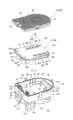
- 1 is an exploded perspective view of a control housing including a heat sink, control board, and motor gear housing employed in a disc brake according to an embodiment of the present invention
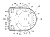
- FIG. FIG. 2 is a plan view of the interior of a control unit housing employed in the disc brake according to the embodiment of the present invention
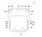
- the top view of the control board employ
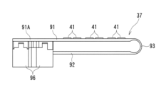
- the side view of the control board employ
- FIG. 4 is a diagram showing the relationship between the thickness of a heat dissipating material employed in the disc brake according to the embodiment of the present invention and the temperature change of the heat-generating electronic component.
- FIG. 4 is a diagram showing the relationship between the thickness of a heat dissipating material employed in the disc brake according to the embodiment of the present invention and the distance between the heat-generating electronic component and the proximal contact portion;
- FIG. 3 is a cross-sectional view of the same aspect as FIG. 2 showing a control board according to another embodiment;
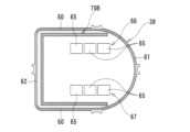
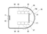
- the top view of the other end surface of the heat sink which shows the contact part of the heat sink which concerns on other embodiment.
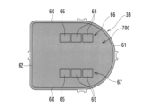
- a plan view of the other end surface of the heat sink showing the contact portion of the heat sink according to still another embodiment.
- FIG. A disc brake 1 is an electric brake device that generates a braking force by driving an electric motor 30 during normal running.
- the vehicle inner side inner side
- the vehicle outer side outer side
- the other end side disk rotor D side
- a disc brake 1 according to this embodiment comprises a pair of inner brake pad 2 and outer brake pad 3 arranged on both sides in the axial direction with a disc rotor D attached to a rotating portion of a vehicle interposed therebetween. , a caliper 4 and .
- This disc brake 1 is constructed as a caliper floating type.
- the pair of inner and outer brake pads 2 and 3 and the caliper 4 are movably supported in the axial direction of the disk rotor D by a carrier 5 fixed to a non-rotating portion such as a knuckle of the vehicle.
- the disk rotor D corresponds to the rotor.
- the inner brake pad 2 and the outer brake pad 3 correspond to friction pads.
- the caliper 4 includes a caliper main body 8, which is the main body of the caliper 4, and a drive unit 9 for applying power to the disk rotor D to press the inner brake pad 2 and the outer brake pad 3. ing.
- the caliper body 8 is arranged on the base end side facing the inner brake pad 2, and has a cylindrical cylinder portion 13 that opens facing the inner brake pad 2, and an outer side extending from the cylinder portion 13 across the disk rotor D.
- a pair of claw portions 14, 14 arranged on the tip side (the other end side) extending to the outer brake pad 3 and facing the outer brake pad 3 are provided. 1, only one of the pair of claw portions 14, 14 is shown.
- a piston 18 is accommodated in the cylinder portion 13 of the caliper body 8, that is, in the cylinder bore 16 of the cylinder portion 13 so as to be axially movable and non-rotatable relative to the cylinder portion 13. It is The piston 18 presses the inner brake pad 2 and is shaped like a cup with a bottom. The piston 18 is housed in the cylinder bore 16 so that its bottom faces the inner brake pad 2 . The piston 18 is supported so as not to rotate relative to the cylinder bore 16 of the cylinder portion 13 and thus to the caliper body 8 by anti-rotation engagement between the bottom portion of the piston 18 and the inner brake pad 2 , for example, uneven engagement.
- a seal member 20 is arranged on the inner peripheral surface of the other end side of the cylinder bore 16 of the cylinder portion 13 .
- the piston 18 is accommodated in the cylinder bore 16 so as to be axially movable while contacting the seal member 20 .
- a dust boot 21 is interposed between the outer wall portion on the bottom side of the piston 18 and the inner peripheral surface on the other end side of the large-diameter cylinder bore 16 . The sealing member 20 and the dust boot 21 prevent foreign matter from entering the cylinder bore 16 of the cylinder portion 13 .
- a motor gear housing 28 is integrally connected to the bottom wall 23 side (one end side) of the cylinder portion 13 .
- An insertion hole 25 is provided in the bottom wall 23 of the cylinder portion 13 , and a spindle 130 , which will be described later, extends into the motor gear housing 28 through the insertion hole 25 .
- a drive unit 9 is arranged in the motor gear housing 28 and the cylinder bore 16 of the cylinder portion 13 . The drive unit 9 transmits the rotation from the electric motor 30 to the piston 18 accommodated in the cylinder bore 16 of the cylinder portion 13, and the thrust of the piston 18 moves the inner brake pad 2 and the outer brake pad 3 to the disk rotor D. It is for pressing to
- the drive unit 9 includes an electric motor 30, a reduction gear mechanism 31 to which rotation from the electric motor 30 is transmitted and to increase the rotational torque from the electric motor 30, and a
- a rotation-to-linear motion conversion mechanism 32 converts the rotation of the piston 18 into a linear motion to apply a thrust force to the piston 18, and cancels the braking force when the electric motor 30 cannot be driven normally due to a failure of the power supply or the like during braking.
- a fail-open mechanism 33 is provided.
- the driving of the electric motor 30 is controlled by commands from the control board 37 of the electronic control device 36 .
- the electric motor 30 and the reduction gear mechanism 31 are arranged within the motor gear housing 28 .
- the reduction gear mechanism 31 increases the rotational torque from the electric motor 30 and transmits it to the rotation/linear motion conversion mechanism 32 .
- the reduction gear mechanism 31 is accommodated in the motor gear housing 28 on the other end side (cylinder portion 13 side) of the electric motor 30 .
- a planetary gear reduction mechanism or the like is adopted as the reduction gear mechanism 31 .
- the electronic control device 36 includes a control board 37 on which heat-generating electronic components 41 are mounted, and a heat sink 38 provided with a heat-dissipating material 42 interposed between the heat-generating electronic components 41 mounted on the control board 37. there is The heat-generating electronic component 41 corresponds to the electronic component.
- the control board 37 receives, for example, a detection signal from a detection sensor corresponding to the driver's request, a detection sensor that detects various situations requiring braking, and a wheel speed detection sensor that detects the wheel speed during braking during normal driving.
- detection signal from a detection signal from a rotation angle detection means (not shown) for detecting the rotation angle of the rotation shaft (not shown) of the electric motor 30, and the thrust from the inner and outer brake pads 2, 3 to the disk rotor D It controls the rotation (rotation direction, rotation speed, etc.) of the electric motor 30 based on various detection signals such as a detection signal from a thrust sensor (not shown) that detects (pressing force).
- the control board 37 is arranged on one end side from the electric motor 30 .
- the electric motor 30 is sandwiched between the control board 37 including the heat-generating electronic components 41 of the electronic control device 36 and the reduction gear mechanism 31 along the axial direction of the rotation shaft.
- a control board 37 including heat-generating electronic components 41 is housed in a control housing 45 .
- the controller housing 45 is integrally connected with the motor gear housing 28 .
- the control unit housing 45 is arranged continuously from the motor gear housing 28 on one end side, that is, on the side opposite to the disc rotor D. As shown in FIG.
- the control unit housing 45 protrudes radially outward of the disk rotor D from the motor gear housing 28 .
- the control housing 45 projects from the motor gear housing 28 toward the bases of the claws 14 , 14 .
- a heat sink 38 is provided at one end side opening of the control unit housing 45 to hermetically close the opening and enhance the heat radiation effect from the control board 37 (the heat-generating electronic component 41).
- the wall portion of the control portion housing 45 on the radial center side of the disk rotor D is curved in an arc shape.
- the control unit housing 45 includes a pair of facing straight wall portions 48, 48, a curved wall portion 49 extending in an arc, and a main straight wall portion 50 facing the curved wall portion 49. and is surrounded by.
- a number of various terminals extend toward one end. Specifically, a motor terminal 53 , a first connector terminal 54 , a second connector terminal 55 and a third connector terminal 56 are arranged in the control unit housing 45 as various terminals.
- a plurality of motor terminals 53 are spaced in series along one opposing straight wall portion 48 and proximate to the opposing straight wall portion 48 . In this embodiment, three motor terminals 53 are arranged on one facing straight wall portion 48 side. Also, a plurality of motor terminals 53 are spaced in series along and adjacent to the other opposing straight wall portion 48 . In this embodiment, three motor terminals 53 are arranged on the other facing straight wall portion 48 side. A plurality of motor terminals 53 electrically connected to the electric motor 30 extend into the control housing 45 as described above.
- a plurality of first connector terminals 54 are spaced apart at a corner between the main straight wall portion 50 of the control housing 45 and the end of one opposing straight wall portion 48 .
- the four first connector terminals 54 are arranged at the four corners of the rectangle.
- a plurality of second connector terminals 55 are spaced apart at a corner between the main straight wall portion 50 of the control housing 45 and the end of the other opposing straight wall portion 48 .
- the four second connector terminals 55 are arranged at the four corners of the rectangle.
- a plurality of third connector terminals 56 are spaced apart centrally and proximate the main straight wall portion 50 of the control housing 45 . In this embodiment, two third connector terminals 56 are spaced apart from each other along the main straight wall portion 50 .
- the heat sink 38 is made of a material with good thermal conductivity, such as an aluminum material.
- the heat sink 38 is formed in a plate shape.
- the heat sink 38 has a pair of facing straight portions 60, 60, a curved portion 61 extending in an arc, and a main straight portion 62 facing the curved portion 61, similar to the outer shape of the one end side opening of the control unit housing 45. and are provided.
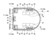
- component corresponding portions 65 are formed at positions corresponding to the plurality of heat-generating electronic components 41 on the first substrate portion 91, which will be described later. Each component corresponding portion 65 projects from the other end surface of the heat sink 38 toward the inside of the control unit housing 45 .
- one component corresponding portion 65 is formed corresponding to two heat-generating electronic components 41 . That is, on the other end face of the heat sink 38, a pair of parallel first and second component corresponding portion rows 66 and 67 are formed in which three component corresponding portions 65 are arranged in series with a space therebetween. The first and second component corresponding portion rows 66 , 67 extend along the opposed linear portions 60 , 60 of the heat sink 38 .
- the first and second component corresponding portion rows 66 and 67 are formed at positions slightly closer to the pair of opposed linear portions 60 and 60 of the heat sink 38, respectively.
- a plurality of abutting portions 70 ⁇ /b>A that abut against the first substrate portion 91 of the control substrate 37 are formed on the other end surface of the heat sink 38 .
- the contact portion 70 ⁇ /b>A protrudes inward from the control portion housing 45 from the other end surface of the heat sink 38 .
- the contact portion 70A includes a distal contact portion 71, first and second intermediate contact portions 72 and 73, and first and second proximal contact portions 74 and 75.
- the distal contact portion 71 is arranged at a position away from the first and second part corresponding part rows 66, 67 (the first and second heat-generating electronic component rows 101, 102).
- the distal contact portion 71 is positioned substantially in the center of the main straight portion 62 of the heat sink 38 .
- the distal side contacting portion 71 includes a rectangular contacting portion 77 (lightly blackened portion in FIG. 5) having a substantially rectangular shape in plan view, and a plurality of distal side contacting portions 71 arranged from the rectangular contacting portion 77 to the curved portion 61 side of the heat sink 38 . and a circular contact portion 78 (thin black portion in FIG. 5) that is substantially circular in plan view.
- the rectangular abutting portion 77 extends along the main straight portion 62 of the heat sink 38 and is arranged close to the main straight portion 62 .
- a plurality of circular contact portions 78 are arranged at intervals from the rectangular contact portion 77 to the curved portion 61 side of the heat sink 38 .
- a plurality of circular contact portions 78 are arranged at intervals along the main linear portion 62 of the heat sink 38 .
- two circular contact portions 78 are formed.
- a plurality of connector terminals 56,56 are positioned between adjacent circular abutments 78,78.
- two third connector terminals 56 , 56 are positioned on the distal contact portion 71 .
- the third connector terminal 56 is indicated by a chain double-dashed line.
- the first and second intermediate abutment portions 72 and 73 are arranged at a distance shorter than the distance between the first or second part corresponding portion row 66 or 67 and the distal abutment portion 71. They are arranged at positions separated from the part corresponding part arrays 66 and 67 (the first and second heat generating electronic component arrays 101 and 102).
- the first and second intermediate abutment portions 72 and 73 are on both sides of the distal abutment portion 71 and are located between both ends of the main straight portion 62 of the heat sink 38 and the ends of the pair of opposing straight portions 60 and 60. at each corner between the .
- the first and second intermediate contact portions 72 and 73 are composed of a rectangular contact portion 80 (thin black portion in FIG.
- a plurality of circular contact portions 81 (lightly blackened portions in FIG. 5) having a substantially circular shape in a plan view are arranged in the .
- the rectangular abutting portion 80 extends along the main straight portion 62 of the heat sink 38 and is arranged close to the main straight portion 62 .
- a plurality of circular contact portions 81 are arranged at intervals from the rectangular contact portion 80 to the curved portion 61 side of the heat sink 38 . In this embodiment, three circular contact portions 81 are arranged so that lines connecting the centers of the contact portions form a triangular shape.
- a plurality of first and second connector terminals 54 or 55 are arranged around these circular contact portions 81 . In this embodiment, four first or second connector terminals 54 or 55 are positioned on the first or second intermediate abutment portion 72 or 73 . In addition, in FIG. 5, the first and second connector terminals 54 and 55 are indicated by two-dot chain lines.
- the first and second proximal contact portions 74, 75 are shorter than the distance between the first or second part corresponding portion row 66 or 67 and the first or second intermediate contact portion 72 or 73. , are arranged at positions separated from the first and second component corresponding part rows 66, 67 (the first and second heat-generating electronic component rows 101, 102), respectively.
- the first and second proximal contact portions 74 and 75 are arranged between the first or second component corresponding portion row 66 or 67 and one or the other opposing linear portion 60 of the heat sink 38, respectively.
- the first proximal contact portion 74 is arranged between the first component corresponding portion row 66 and one opposing linear portion 60 of the heat sink 38 .
- the second proximal contact portion 75 is arranged between the second component corresponding portion row 67 and the other opposing linear portion 60 of the heat sink 38 .
- the first and second proximal side contact portions 74 and 75 are composed of a rectangular contact portion 83 (thin black portion in FIG. 5) having a substantially rectangular shape in plan view, and first and second contact portions extending from the rectangular contact portion 83 .
- a plurality of circular contact portions 84 (thin black portions in FIG. 5) having a substantially circular shape in plan view are arranged on the side of the component corresponding portion rows 66 and 67 .
- the rectangular contact portion 83 is arranged along the facing straight portion 60 of the heat sink 38 and in close proximity to the facing straight portion 60 .
- a plurality of circular contact portions 84 are arranged at intervals from the rectangular contact portion 83 to the first or second component corresponding portion row 66 or 67 side.
- Each of the circular abutments 84 are spaced apart in series along the opposed straight portions 60 of the heat sink 38 .
- four circular contact portions 84 are formed.
- Motor terminals 53 are located between adjacent circular abutments 84, 84, respectively.
- Three motor terminals 53 are positioned on the first and second proximal contact portions 74 and 75, respectively.
- the motor terminal 53 is indicated by a chain double-dashed line.
- each motor terminal 53 is positioned between the rectangular contact portion 83 and the first component corresponding portion row 66 .
- each motor terminal 53 is positioned between the rectangular contact portion 83 and the second component corresponding portion row 67 .
- each motor terminal 53 is located between the rectangular contact portion 83 of the first proximal contact portion 74 and the heat-generating electronic component 41 on the first substrate portion 91 .
- each motor terminal 53 is positioned between the rectangular contact portion 83 of the second proximal side contact portion 75 and the heat-generating electronic component 41 on the first substrate portion 91 .
- a plurality of motor terminals 53 are provided between the rectangular contact portion 83 of the first proximal contact portion 74 and the rectangular contact portion 83 of the second proximal contact portion 75. ) is placed.
- the distance between the first proximal contact portion 74 and the first component corresponding portion row 66, that is, the first heat-generating electronic component row 101, the distance between the second proximal contact portion 75 and the second The distance to the component corresponding portion row 67, that is, the distance to the second heat-generating electronic component row 102 is substantially the same, and the distance is the shortest. Also, the distance between the distal side contact portion 71 and the first component corresponding portion row 66, that is, the first heat generating electronic component row 101, and the distance between the distal side contact portion 71 and the second component corresponding portion row 67, that is, The distance to the second heat-generating electronic component row 102 is substantially the same, and the distance is the longest.
- a part of the first or second part corresponding part row 66 or 67 is arranged between the first or second proximal contact part 74 or 75 and the distal contact part 71 .
- the heat-generating electronic component 41 on the first board portion 91 of the control board 37 is arranged between the first or second proximal contact portion 74 or 75 and the distal contact portion 71.
- a large number of heat radiation fins 95 are provided on the outer peripheral surface (one end surface) of heat sink 38 .
- the heat sink 38 increases its volume to ensure thermal mass (heat capacity), the heat of each heat-generating electronic component 41 is not directed to the control board 37 side, which has a small thermal mass, but to the heat sink 38, which has a large thermal mass. Heat is efficiently dissipated to the outside air through the side.
- the control board 37 is composed of a flexible board.
- the control board 37 is composed of a first board portion 91 and a second board portion 92 which are formed by bending one long control board into two layers.
- the control board 37 is provided between the first board section 91 , the second board section 92 arranged to face the first board section 91 , and the first board section 91 and the second board section 92 . and a folded portion 93 .
- the first substrate portion 91 and the second substrate portion 92 are arranged facing each other with a predetermined distance therebetween along the axial direction of the disk rotor D. As shown in FIG.
- the first substrate portion 91 and the second substrate portion 92 are biased in a direction to separate from each other with the folded portion 93 as a reference.
- Both the first substrate portion 91 and the second substrate portion 92 are formed in a substantially rectangular shape.
- the first substrate portion 91 is positioned on the heat sink 38 side.
- the second substrate portion 92 is positioned on the electric motor 30 side (disk rotor D side).
- the folded portion 93 is positioned on the curved wall portion 49 side of the control portion housing 45 .
- a plurality of heat-generating electronic components 41 such as semiconductor switching elements (MOSFETs) and capacitors are mounted on the first substrate portion 91 .
- Each heat-generating electronic component 41 is mounted on the surface of the first substrate portion 91 on the side of the heat sink 38 .
- First and second heat-generating electronic component rows 101 and 102 in which a plurality of heat-generating electronic components 41 are arranged in series at intervals are arranged in parallel on the first substrate portion 91 .
- first and second heat-generating electronic component rows 101 and 102, in which six heat-generating electronic components 41 are arranged in series at intervals are arranged in two parallel rows on the first substrate portion 91. As shown in FIG.
- the first heat-generating electronic component row 101 on the first substrate portion 91 corresponds to the first component corresponding portion row 66 of the heat sink 38
- the first substrate The second heat-generating electronic component row 102 on the portion 91 corresponds to the second component corresponding portion row 67 of the heat sink 38
- the six heat-generating electronic components 41 in the first heat-generating electronic component row 101 on the first substrate portion 91 correspond to the three component-corresponding parts 65 in the first component-corresponding part row 66 of the heat sink 38. .
- the six heat-generating electronic components 41 in the second heat-generating electronic component row 102 on the first substrate portion 91 correspond to the three component-corresponding parts 65 in the second component-corresponding part row 67 of the heat sink 38 .
- Each heat-generating electronic component 41 on the first substrate portion 91 is closely attached to the corresponding component-corresponding portion 65 of the heat sink 38 with the heat dissipating material 42 interposed therebetween.
- the heat dissipation material 42 is composed of a non-fluid or fluid material. Adhesives, heat radiation sheets, and the like, which are excellent in heat radiation, are used as non-fluid materials. On the other hand, heat-dissipating gel, grease, or the like is used as the fluid material.
- the area of the first substrate portion 91 is larger than the area of the second substrate portion 92 .
- the first board portion 91 protrudes toward the main linear wall portion 50 side of the control portion housing 45 along the longitudinal direction with respect to the second board portion 92 .
- the first board portion 91 is provided with a board protruding portion 91 ⁇ /b>A at a position not overlapping the second board portion 92 on the main straight wall portion 50 side of the control portion housing 45 .
- a tall component 96 such as an electrolytic capacitor that is longer than the predetermined distance between the first substrate portion 91 and the second substrate portion 92 is provided on the substrate projecting portion 91A of the first substrate portion 91 .
- the board protruding part 91A of the first board part 91 is arranged inside a portion of the control part housing 45 protruding from the motor gear housing 28 .
- a plurality of first connector terminal connection holes 105 corresponding to the plurality of first connector terminals 54 are formed on one end side in the width direction of the substrate protruding portion 91A of the first substrate portion 91 .
- a plurality of second connector terminal connection holes 106 corresponding to the plurality of second connector terminals 55 are formed on the other widthwise end side of the substrate projecting portion 91A of the first substrate portion 91 .
- a plurality of third connector terminal connection holes 107 corresponding to the plurality of third connector terminals 56 are formed in the width direction center of the substrate projecting portion 91A of the first substrate portion 91 .
- the first substrate portion 91 is formed with substrate projecting portions 91B, 91B projecting outward from both ends in the width direction with respect to the second substrate portion 92, respectively.
- the first substrate portion 91 is provided with a pair of substrate protruding portions 91B, 91B along its width direction at positions that do not overlap with the second substrate portion 92 .
- a plurality of motor terminal connection holes 108 corresponding to the plurality of motor terminals 53 are formed in the board protruding portions 91B, 91B, respectively.
- the first board portion 91 is electrically connected to the electric motor 30 via each motor terminal 53 .
- a first connector 111, a second connector 112 and a third connector 113 are electrically connected to the first board portion 91 and the second board portion 92 of the control board 37, respectively.
- the first connector 111, the second connector 112, and the third connector 113 are arranged at positions overlapping the substrate projecting portion 91A of the first substrate portion 91 of the electronic control unit 36 in the axial direction of the disk rotor D. 1 and 3, a first connector 111, a second connector 112, and a third connector 113 extend along the axial direction of the disk rotor D from a portion of the control unit housing 45 protruding from the motor gear housing 28. , the other end, that is, the disk rotor D side.
- the first connector 111, the second connector 112 and the third connector 113 are arranged in a row. Specifically, the first connector 111 , the second connector 112 and the third connector 113 are arranged in a line along the main straight wall portion 50 of the control housing 45 .
- the third connector 113 is arranged so as to be sandwiched between the first connector 111 and the second connector 112 .
- a plurality of first connector terminals 54 extend from the first connector 111 into the controller housing 45 .
- a plurality of second connector terminals 55 extend from the second connector 112 into the control housing 45 .
- a plurality of third connector terminals 56 extend from the third connector 113 into the control housing 45 .
- the positions of the first connector terminals 54, the second connector terminals 55, and the third connector terminals 56 in the control unit housing 45 have already been described above, so detailed description thereof will be omitted here.
- the control board 37 is positioned within the control housing 45 along a plane by a plurality of positioning snap-fits 116, and contacts the distal side of the heat sink 38.
- the contact portion 71, the first and second intermediate contact portions 72, 73, and the first and second proximal side contact portions 74, 75 allow the first substrate portion 91 and the first substrate portion 91 and the second base plate portion 91 to
- the two substrate portions 92 are arranged so as to overlap each other with the folded portion 93 interposed therebetween.
- the control board 37 is installed in the control unit housing 45 in a state in which the first board part 91 is urged in the direction of coming into contact with the heat sink 38 due to the restoring force of the folded part 93 .
- each of the heat-generating electronic components 41 (first and second heat-generating electronic component rows 101 and 102) on the first substrate portion 91 is connected to each of the component-corresponding portions 65 ((first and second component-corresponding portions 66) of the heat sink 38. , 67) are biased via the heat dissipation material 42.
- the heat sink 38 causes the first substrate portion 91 and the second substrate portion 92 to overlap with each other with the folded portion 93 interposed therebetween, so that the control portion housing is closed. 45, the distal contact portion 71 of the heat sink 38 allows the third connector terminals 56 to be easily press-fitted into the third connector terminal connection holes 107 of the first substrate portion 91. can.
- the motor terminals 53 can be easily press-fitted into the motor terminal connection holes 108 of the first substrate portion 91 by the first and second proximal contact portions 74 and 75 of the heat sink 38 .
- the first and second intermediate contact portions 72 and 73 of the heat sink 38 connect the first and second connector terminals 54 and 55 to the first and second connector terminal connection holes 105 and 105 of the first substrate portion 91 , respectively.
- 106 can be easily press-fitted respectively.
- the heat sink 38 is temporarily fixed to the control unit housing 45 by a plurality of temporary fixing snap fits 118 . After that, the heat sink 38 is permanently fixed to the control unit housing 45 with an adhesive or the like.
- the distal contact portion 71, the first and second intermediate contact portions 72, 73, and the first and second proximal contact portions 74, 75 of the heat sink 38 are independent. It is only abutted on the first substrate portion 91 without being fixed to the first substrate portion 91 by a screw member or the like.
- the third connector terminals 56 are press-fitted into the third connector terminal connection holes 107 of the first board portion 91 of the control board 37 , and are inserted into the motor terminal connection holes 108 of the first board portion 91 .
- the control board 37 are fixed and supported within the controller housing 45 .
- the relationship between the thickness of the heat-dissipating material 42 (the gap between the heat-generating electronic component 41 and the heat sink 38) and the temperature change of the heat-generating electronic component 41 is shown in FIG.
- the heat radiation material 42 has an inflection point at a thickness of 0.3 mm, and the temperature change of the heat-generating electronic component 41 is suppressed more effectively in a region where the thickness of the heat radiation material 42 is 0.3 mm or less. I understand what you can do.
- the maximum eccentric width of the thickness of the heat dissipation material 42, the heat-generating electronic component 41 and the proximal side contact portion 74 or 75 is as shown in FIG.
- the maximum eccentric width of the thickness of the heat radiating material 42 is 0.15 mm or less regardless of the type of the heat radiating material 42. Therefore, it can be seen that the thickness of the heat radiating material 42 is 0.3 mm or less.
- the non-flowing type is deformation events of "flatness” and “initial warpage”
- the flow type is "flatness”, “initial warpage”
- thermal strain (thickness deformation) and thermal strain (warpage) are taken into account in the calculation.
- the rotation/linear motion conversion mechanism 32 is arranged between the bottom of the cylinder portion 29 and the piston 36 within the cylinder bore 34 of the cylinder portion 29 .
- the rotation-to-linear motion converting mechanism 32 converts the rotary motion from the reduction gear mechanism 31 into linear motion to give thrust to the piston 36 .
- the rotation-to-linear motion conversion mechanism 32 includes a spindle 130 to which rotation from the reduction gear mechanism 31 is transmitted, and a nut member 131 screwed with the spindle 130 .
- a spindle 130 is non-rotatably connected to an output member (not shown) of the reduction gear mechanism 31 within the motor gear housing 28 . As a result, rotational torque can be transmitted between the output member of the reduction gear mechanism 31 and the spindle 130 .
- a thrust bearing 136 is arranged between the annular support portion 134 of the spindle 130 and the bottom wall 23 of the cylinder portion 13 .
- the thrust bearing 136 rotatably supports the spindle 130 on the bottom wall 23 of the cylinder portion 13 .
- the thrust bearing 136 includes a cylindrical thrust member 138 arranged on the side of the bottom wall 23 of the cylinder portion 13 and a plurality of rollers rotatably arranged between the thrust member 138 and the annular support portion 134 of the spindle 130 . and a thrust ball 139 .
- the spindle 130 is provided with a cylindrical support portion 141 on the other end side from the annular support portion 134 .
- An annular groove portion 143 is formed on the outer peripheral surface of the cylindrical support portion 141 .
- a spring clutch 151 which will be described later, is arranged in this annular groove portion 143 .
- a nut member 131 is arranged radially outside the male threaded portion 145 of the spindle 130 .
- Nut member 131 is formed in a cylindrical shape.
- a female threaded portion 146 is formed on the inner peripheral surface of the nut member 131 on the one end side. The male threaded portion 145 of the spindle 130 and the female threaded portion 146 of the nut member 131 are screwed together.
- the nut member 131 is supported so as not to rotate relative to the piston 18 and thus to the cylinder portion 13 . This allows the nut member 131 to move freely along the axial direction as the spindle 130 rotates.
- the fail-open mechanism 33 includes a fixing member 148 , a torque transmission member 149 , a torsion spring 150 and a spring clutch 151 .
- the fixing member 148 is formed in a cylindrical shape as a whole.
- the nut member 131 is inserted through the fixing member 148, and relative rotation between the fixing member 148 and the nut member 131 is restricted.
- the fixed member 148 is supported so as not to rotate relative to the piston 18 and the nut member 131 and thus the cylinder portion 13 .
- the other end of the fixing member 148 is provided with an annular projecting portion 154 projecting radially outward in an annular shape.
- the other end of the torsion spring 150 is connected to the annular projecting portion 154 .
- a torque transmission member 149 is arranged to radially cover one end side of the annular projecting portion 154 of the fixing member 148 and the annular support portion 134 of the spindle 130 .
- Torque transmission member 149 is formed in a cylindrical shape as a whole.
- One end of the torsion spring 150 is connected to one end of the torque transmission member 149 .
- the fixing member 148 and the torque transmission member 149 are connected via the torsion spring 150 .
- An engagement slit portion 156 is provided on one end side of the torque transmission member 149 .
- the tip portion of the spring clutch 151 is engaged with the engagement slit portion 156 .
- the coil portion of the spring clutch 151 is arranged between the annular groove portion 143 provided on the outer peripheral surface of the cylindrical support portion 141 of the spindle 130 and the torque transmission member 149 .
- the spring clutch 151 functions as a one-way torque limiter that provides rotational resistance only to one-way rotation of the spindle 130 (in this embodiment, rotation in the braking direction).
- detection signals from detection sensors that detect various situations that require braking or detection sensors that correspond to the driver's request are first or second. It is input to the control board 37 of the electronic control device 36 via the second connector 111 or 112 .
- a detection signal from a wheel speed detection sensor for detecting wheel speed is input to the control board 37 of the electronic control unit 36 via the third connector 113 .
- the control board 37 includes a detection signal from a rotation angle detection means for detecting the rotation angle of the rotation shaft of the electric motor 30, and a thrust sensor for detecting the thrust from the inner and outer brake pads 2, 3 to the disk rotor D.
- a detection signal or the like from is input.
- power is supplied to the control board 37 via the first or second connector 111 or 112 from a power supply device (not shown).
- the control board 37 of the electronic control device 36 operates the drive unit 9 based on these detection signals. That is, the rotation of the electric motor 30 in the braking direction is transmitted to the reduction gear mechanism 31 . Subsequently, the rotation increased by the reduction gear mechanism 31 is transmitted to the rotation/linear motion converting mechanism 32 .
- the spindle 130 of the rotation/linear motion conversion mechanism rotates with the rotation of the reduction gear mechanism 31, the nut member 131 screwed with the spindle 130 advances and the piston 18 advances.
- the inner brake pad 2 is pressed against the disc rotor D by advancing the piston 18 .
- the caliper body 8 moves toward the inner side with respect to the carrier 5 due to the reaction force against the pressing force of the piston 18 to the inner brake pad 2, and the outer brake pad 3 is moved to the disc rotor D by the claw portions 14, 14. impose.
- the disc rotor D is sandwiched between the pair of inner and outer brake pads 2, 3 to generate frictional force, which in turn generates braking force for the vehicle.
- the electric motor 30 is rotated in the brake release direction by a command from the control board 37 of the electronic control unit 36 . Subsequently, rotation in the braking direction from the electric motor 30 is transmitted to the rotation/linear motion conversion mechanism 32 via the reduction gear mechanism 31 .
- the spindle 130 of the rotation-to-linear motion converting mechanism 32 rotates in the braking release direction
- the nut member 131 and the piston 18 screwed with the spindle 130 are retracted to their initial positions, and the inner brake pads 2 and A predetermined clearance is provided between the outer brake pad 3 and the disc rotor D, and the braking force is released.
- the rotation of the spindle 130 in the brake release direction is not transmitted to the torque transmission member 149 via the spring clutch 151. rotates in the braking release direction and returns to the initial position.
- the fail-open mechanism 33 operates. That is, if the electric motor 30 is not normally driven during braking, the torsion spring 150 elastically deformed during braking is restored. Then, the restoring force of the torsion spring 150 causes the torque transmission member 149 to rotate in the braking release direction. As the torque transmission member 149 rotates in the brake release direction, the spindle 130 rotates in the brake release direction. As a result, the nut member 131 and the piston 18 retreat, and the braking force exerted on the disc rotor D by the pair of inner and outer brake pads 2, 3 is reduced.
- the heat sink 38 includes the distal side contact portion 71, the first and second contact portions 70A that contact the first substrate portion 91 of the control substrate 37, and Intermediate abutment portions 72, 73 and first and second proximal abutment portions 74, 75 are provided, the first and second proximal abutment portions 74, 75 corresponding to the first and second components. It is arranged closest to the part arrays 66, 67, that is, the first and second heat-generating electronic component arrays 101, 102 (each heat-generating electronic component 41). Moreover, it is preferable to set the distance between the first or second proximal side contact portion 74 or 75 and each heat-generating electronic component 41 to 4.0 mm or less.
- each heat-generating electronic component 41 of the first and second heat-generating electronic component rows 101 and 102 can be suppressed.
- variations in the distance between the heat-generating electronic component 41 and the heat sink 38, that is, in the thickness of the heat dissipating material 42 can be suppressed, and the thinness of the heat dissipating material 42 can be managed.
- the heat dissipation efficiency of the heat dissipating material 42 can be secured satisfactorily, and the temperature rise of each heat-generating electronic component 41 can be suppressed.
- the protrusions provided on the heat sink contact the substrate when the substrate is deformed, but do not contact the substrate during initial assembly. Only the bolt fixing points near the outer periphery serve as abutting portions. Therefore, the distance from the electronic component to the abutment portion is long, and there is a risk that the thickness of the heat dissipating material interposed between the electronic component and the heat sink may become less accurate during assembly. The effect of the disk brake 1 according to the form cannot be obtained.
- each heat-generating electronic component 41 is mounted on the surface of the first substrate portion 91 on the side of the heat sink 38, and each heat-generating electronic component 41 on the first substrate portion 91 (the second 1 and 2 heat-generating electronic component rows 101, 102) are kept in close contact with respective component-corresponding portions 65 (first and second component-corresponding portions 66, 67) of the heat sink 38 via the heat dissipating material 42. can be done. As a result, good heat radiation efficiency can be ensured by the heat radiation material 42 and the heat sink 38 .
- the heat sink is arranged on the non-mounting surface side of the substrate where the heat-generating electronic components are not mounted. Since the heat from the disk is transmitted to the heat sink through the substrate, the heat dissipation loss is large, and the effect of the disk brake 1 according to the present embodiment described above cannot be obtained.
- the heat sink 38 includes the distal side contact portion 71, the first and second intermediate contact portions 70A as the contact portion 70A that contacts the first substrate portion 91 of the control substrate 37, and the first and second intermediate contact portions.
- Abutments 72, 73 and first and second proximal abutments 74, 75 are provided, which are distal abutments 71, first and second intermediate abutments 72,73. , and the first and second proximal contact portions 74 and 75 are in contact with the first substrate portion 91 without being bolted to the first substrate portion 91 .
- first and second proximal side contact portions 74 and 75 of the heat sink 38 are It can be arranged as close as possible to the first and second component corresponding part rows 66, 67, that is, the first and second heat-generating electronic component rows 101, 102 (each heat-generating electronic component 41).
- each motor is provided between the first or second proximal contact portion 74 or 75 of the heat sink 38 and each heat-generating electronic component 41 on the first substrate portion 91 .
- a terminal 53 is located.
- each motor terminal 53 is positioned in the vicinity of the first and second proximal contact portions 74 and 75 of the heat sink 38, respectively.
- each motor terminal 53 is positioned between the first proximal contact portion 74 and the second proximal contact portion 75 of the heat sink 38 .
- the motor terminals 53 from the electric motor 30 are connected by the first and second proximal contact portions 74 and 75 of the heat sink 38 to the second contact portions. They can be easily press-fitted into the respective motor terminal connection holes 108 of the 1 board portion 91 with high accuracy.
- the control board 37 is composed of the first board portion 91 and the second board portion 92 formed by bending one long control board into two layers.
- the control board 37 is assembled in the control unit housing 45, the control board 37 is installed in a state in which the first board part 91 is urged in the direction of coming into contact with the heat sink 38 due to the restoring force of the folded part 93. be done.
- the first substrate portion 91 of the control substrate 37 is connected to the distal contact portion 71, the first and second intermediate contact portions 72, 73, and the first and second proximal contact portions of the heat sink 38.
- 74 and 75 are reliably brought into contact with each other, the heat radiation efficiency from the control board 37 is improved, and the temperature rise of the control board 37 can be suppressed.
- the control board 37 is composed of the first board portion 91 and the second board portion 92, which are formed by bending one long control board into two layers. As shown in FIG. 10, the control board 37 may simply be configured in one layer.
- a contact portion 70B provided on the heat sink 38 As shown in FIG. 11, as a contact portion 70B provided on the heat sink 38 according to another embodiment, a distal side contact portion 71 and first and second intermediate contact portions 72 and 73 shown in FIG. and the first and second proximal side contact portions 74 and 75 are provided continuously and integrally, and the first and second component corresponding portion rows 66 and 67 are surrounded from the main straight portion 62 side, in plan view A letter-shaped contact portion 70B (thin black portion in FIG. 11) may be provided. This increases the area of the contact portion 70 ⁇ /b>B in addition to the heat dissipation and ease of assembly described above, so that the stress applied to the control board 37 can be dispersed.
- the other end surface of the heat sink 38 has first and second component corresponding portion rows 66 and 67 (each component corresponding portion A contact portion 70C (thin black portion in FIG. 12) may be provided over the entire region other than 65).
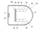
- the second contact portion of the heat sink 38 is provided.
- a proximal contact portion 170 (light black in FIG. 13) extending from the first and second component corresponding portion rows 66, 67 toward the main straight portion 62 so as to be orthogonal to the first and second component corresponding portion rows 66, 67.
- a coating portion may be provided.
- a part of the proximal contact portion 170 becomes the first and second component corresponding portion rows 66 and 67 of the heat sink 38 , that is, the first and second heat generating electronic component rows 101 and 102 of the first substrate portion 91 . (Each heat-generating electronic component 41 ) and the distal contact portion 71 . This facilitates the layout of electronic components on the outer peripheral portion of the first substrate portion 91 of the control substrate 37 in addition to the above-described heat dissipation and ease of assembly.
- the contact portion 70E provided on the heat sink 38 is the second contact portion of the heat sink 38.
- a proximal contact portion 171 extending from the first and second component corresponding portion rows 66 and 67 toward the curved portion 61 so as to be orthogonal to the first and second component corresponding portion rows 66 and 67 (lightly blacked out in FIG. 14). part) may be provided.
- the first and second component corresponding portion rows 66, 67 of the heat sink 38 that is, the first and second heat-generating electronic component rows 101, 102 (each heat-generating electronic component 41) of the first substrate portion 91 are located on the proximal side. It will be positioned between the abutment portion 171 and the distal abutment portion 71 .
- proximal side contact portions are provided on both left and right sides of the first and second component corresponding portion rows 66 and 67 of the heat sink 38, that is, the first and second heat generating electronic component rows 101 and 102 of the first substrate portion 91. 171 and the distal contact portion 71 are positioned, it is possible to suppress variations in the thickness of the heat dissipating material 42 corresponding to the plurality of heat-generating electronic components 41 .
- the present invention is not limited to the above-described embodiments, and includes various modifications.
- the above-described embodiments have been described in detail in order to explain the present invention in an easy-to-understand manner, and are not necessarily limited to those having all the configurations described.
- part of the configuration of one embodiment can be replaced with the configuration of another embodiment, and the configuration of another embodiment can be added to the configuration of one embodiment.
Landscapes
- Engineering & Computer Science (AREA)
- General Engineering & Computer Science (AREA)
- Microelectronics & Electronic Packaging (AREA)
- Mechanical Engineering (AREA)
- Power Engineering (AREA)
- Transportation (AREA)
- Physics & Mathematics (AREA)
- Thermal Sciences (AREA)
- Cooling Or The Like Of Electrical Apparatus (AREA)
- Braking Arrangements (AREA)
Abstract
Description
本発明の実施形態に係るディスクブレーキ1は、通常走行時、電動モータ30の駆動によって制動力を発生させる電動ブレーキ装置である。なお、以下の説明において、車両内側(インナ側)を一端側(ヒートシンク38側)と称し、車両外側(アウタ側)を他端側(ディスクロータD側)と称して、適宜説明する。
Claims (13)
- 電子制御装置であって、該電子制御装置は、
基板と、該基板に実装された電子部品と、該電子部品に対して放熱材を挟んで設けられたヒートシンクと、を備え、
前記ヒートシンクは、
前記電子部品から離れた位置で、前記基板に当接する遠位側当接部と、
前記電子部品と前記遠位側当接部との間の距離より短い距離で、前記電子部品から離間する位置に、前記基板に固定されることなく前記基板に当接する近位側当接部と、
を少なくとも含む、電子制御装置。 - 請求項1に記載の電子制御装置であって、
前記遠位側当接部は、前記基板に固定されることなく前記基板に当接される、電子制御装置。 - 請求項1に記載の電子制御装置であって、
前記基板は、端子によって固定される、電子制御装置。 - 請求項1に記載の電子制御装置であって、
前記電子部品と前記近位側当接部との間に、端子が配置される、電子制御装置。 - 請求項4に記載の電子制御装置であって、
前記端子は、電動モータのモータ端子である、電子制御装置。 - 請求項1に記載の電子制御装置であって、
前記近位側当接部は、2箇所備えられ、
前記端子は、第1近位側当接部と第2近位側当接部との間に配置される、電子制御装置。 - 請求項1に記載の電子制御装置であって、
前記近位側当接部は、前記電子部品と、前記遠位側当接部との間に配置される、電子制御装置。 - 請求項1に記載の電子制御装置であって、
前記電子部品は、前記近位側当接部と、前記遠位側当接部との間に配置される、電子制御装置。 - 請求項1に記載の電子制御装置であって、
前記遠位側当接部と前記近位側当接部とが連続して一体的に設けられている、電子制御装置。 - 請求項1に記載の電子制御装置であって、
前記基板は、第1基板部と、該第1基板部から折り曲げられて、前記第1基板部と対向して配置された第2基板部と、を備え、
前記電子部品は、前記第1基板部に実装され、
前記基板は、前記第1基板部が前記ヒートシンク側に付勢された状態で設置される、電子制御装置。 - 請求項1に記載の電子制御装置であって、
前記放熱材は、非流動型または流動型である、電子制御装置。 - 電動ブレーキ装置であって、
車輪と共に回転するロータに摩擦パッドを押圧させるための動力を与える電動モータと、
該電動モータの駆動を制御する電子制御装置と、を備え、
前記電子制御装置は、
基板と、
該基板に実装された電子部品と、
該電子部品に対して放熱材を挟んで設けられたヒートシンクと、を備え、
該ヒートシンクは、
前記電子部品から離れた位置で、前記基板に当接する遠位側当接部と、
前記電子部品と前記遠位側当接部との間の距離より短い距離で、前記電子部品から離間する位置に、固定されることなく前記基板に当接する近位側当接部と、
を少なくとも含む、電動ブレーキ装置。 - 請求項12に記載の電動ブレーキ装置であって、
前記遠位側当接部は、固定されることなく前記基板に当接する、電動ブレーキ装置。
Priority Applications (5)
| Application Number | Priority Date | Filing Date | Title |
|---|---|---|---|
| CN202280060256.4A CN117917199A (zh) | 2021-12-21 | 2022-11-22 | 电子控制装置及电动制动装置 |
| KR1020237044566A KR102895667B1 (ko) | 2021-12-21 | 2022-11-22 | 전자 제어 장치 및 전동 브레이크 장치 |
| DE112022006103.0T DE112022006103T5 (de) | 2021-12-21 | 2022-11-22 | Elektronische Steuervorrichtung und elektrische Bremsvorrichtung |
| US18/691,576 US20240389279A1 (en) | 2021-12-21 | 2022-11-22 | Electronic control apparatus and electric brake apparatus |
| JP2023569190A JP7847158B2 (ja) | 2021-12-21 | 2022-11-22 | 電子制御装置及び電動ブレーキ装置 |
Applications Claiming Priority (2)
| Application Number | Priority Date | Filing Date | Title |
|---|---|---|---|
| JP2021207112 | 2021-12-21 | ||
| JP2021-207112 | 2021-12-21 |
Publications (1)
| Publication Number | Publication Date |
|---|---|
| WO2023120004A1 true WO2023120004A1 (ja) | 2023-06-29 |
Family
ID=86902247
Family Applications (1)
| Application Number | Title | Priority Date | Filing Date |
|---|---|---|---|
| PCT/JP2022/043130 Ceased WO2023120004A1 (ja) | 2021-12-21 | 2022-11-22 | 電子制御装置及び電動ブレーキ装置 |
Country Status (6)
| Country | Link |
|---|---|
| US (1) | US20240389279A1 (ja) |
| JP (1) | JP7847158B2 (ja) |
| KR (1) | KR102895667B1 (ja) |
| CN (1) | CN117917199A (ja) |
| DE (1) | DE112022006103T5 (ja) |
| WO (1) | WO2023120004A1 (ja) |
Cited By (1)
| Publication number | Priority date | Publication date | Assignee | Title |
|---|---|---|---|---|
| WO2025099793A1 (ja) * | 2023-11-06 | 2025-05-15 | Astemo株式会社 | 電動装置及びこの電動装置を備えた緩衝器 |
Families Citing this family (4)
| Publication number | Priority date | Publication date | Assignee | Title |
|---|---|---|---|---|
| JP7442018B2 (ja) * | 2021-05-28 | 2024-03-01 | 日立Astemo株式会社 | 電動ブレーキ装置及び電動ディスクブレーキ |
| US12385539B2 (en) * | 2022-10-03 | 2025-08-12 | Akebono Brake Industry Co., Ltd. | Nut trapping two-piece piston |
| DE102024208122A1 (de) * | 2024-08-27 | 2026-03-05 | Robert Bosch Gesellschaft mit beschränkter Haftung | Antriebseinheit für eine elektromechanische Bremse, elektromechanische Bremse und Fahrzeugbremsanlage |
| FR3171261A1 (fr) * | 2025-01-15 | 2026-07-17 | Hitachi Astemo France | logement de réception d'une carte électronique formant une Pièce de protection de connecteur pour frein électrique et frein comportant une telle pièce de protection |
Citations (2)
| Publication number | Priority date | Publication date | Assignee | Title |
|---|---|---|---|---|
| JP2015088629A (ja) * | 2013-10-31 | 2015-05-07 | 日立オートモティブシステムズ株式会社 | 電子制御装置 |
| WO2020166584A1 (ja) * | 2019-02-15 | 2020-08-20 | 積水テクノ成型株式会社 | 放熱体、放熱構造体及び電子機器 |
Family Cites Families (5)
| Publication number | Priority date | Publication date | Assignee | Title |
|---|---|---|---|---|
| JP2004179239A (ja) * | 2002-11-25 | 2004-06-24 | Hitachi Unisia Automotive Ltd | 電子部品装置 |
| JP4521369B2 (ja) | 2006-02-28 | 2010-08-11 | 日立オートモティブシステムズ株式会社 | 電動ブレーキ装置 |
| JP2008253049A (ja) | 2007-03-30 | 2008-10-16 | Mitsuba Corp | 電動モータ |
| JP6146380B2 (ja) | 2014-07-31 | 2017-06-14 | 株式会社デンソー | 電子装置 |
| JP6183314B2 (ja) | 2014-07-31 | 2017-08-23 | 株式会社デンソー | 電子装置及びそれを備えた駆動装置 |
-
2022
- 2022-11-22 CN CN202280060256.4A patent/CN117917199A/zh active Pending
- 2022-11-22 DE DE112022006103.0T patent/DE112022006103T5/de active Pending
- 2022-11-22 KR KR1020237044566A patent/KR102895667B1/ko active Active
- 2022-11-22 US US18/691,576 patent/US20240389279A1/en active Pending
- 2022-11-22 JP JP2023569190A patent/JP7847158B2/ja active Active
- 2022-11-22 WO PCT/JP2022/043130 patent/WO2023120004A1/ja not_active Ceased
Patent Citations (2)
| Publication number | Priority date | Publication date | Assignee | Title |
|---|---|---|---|---|
| JP2015088629A (ja) * | 2013-10-31 | 2015-05-07 | 日立オートモティブシステムズ株式会社 | 電子制御装置 |
| WO2020166584A1 (ja) * | 2019-02-15 | 2020-08-20 | 積水テクノ成型株式会社 | 放熱体、放熱構造体及び電子機器 |
Cited By (1)
| Publication number | Priority date | Publication date | Assignee | Title |
|---|---|---|---|---|
| WO2025099793A1 (ja) * | 2023-11-06 | 2025-05-15 | Astemo株式会社 | 電動装置及びこの電動装置を備えた緩衝器 |
Also Published As
| Publication number | Publication date |
|---|---|
| JPWO2023120004A1 (ja) | 2023-06-29 |
| KR20240012551A (ko) | 2024-01-29 |
| DE112022006103T5 (de) | 2024-10-24 |
| CN117917199A (zh) | 2024-04-19 |
| US20240389279A1 (en) | 2024-11-21 |
| KR102895667B1 (ko) | 2025-12-03 |
| JP7847158B2 (ja) | 2026-04-16 |
Similar Documents
| Publication | Publication Date | Title |
|---|---|---|
| KR102895667B1 (ko) | 전자 제어 장치 및 전동 브레이크 장치 | |
| US20250196833A1 (en) | Brake caliper for a disc brake | |
| JP4754390B2 (ja) | 電動ブレーキ装置 | |
| US11460082B2 (en) | Self-lock high-efficient rotary to linear mechanism | |
| CN103573871A (zh) | 盘式制动器 | |
| JP2008095909A (ja) | 電動ブレーキ装置 | |
| KR100566367B1 (ko) | 가요성 요소를 포함하는 작동기와, 이러한 작동기를 포함하는 브레이크 캘리퍼 | |
| CN115342164A (zh) | 具有整体力测量的滚珠丝杠组件 | |
| CN115485173B (zh) | 制动装置 | |
| WO2021215157A1 (ja) | ディスクブレーキ | |
| WO2019159405A1 (ja) | 電動駆動装置及び電動パワーステアリング装置 | |
| JP5845153B2 (ja) | キャリパブレーキ装置 | |
| JP7588255B2 (ja) | ディスクブレーキ | |
| JP7442018B2 (ja) | 電動ブレーキ装置及び電動ディスクブレーキ | |
| CN112334677A (zh) | 盘式制动器 | |
| JP7261603B2 (ja) | 電動駆動装置及び電動パワーステアリング装置 | |
| CN115704431A (zh) | 用于盘式制动器的制动衬块 | |
| JP7726843B2 (ja) | 車両用ブレーキ装置 | |
| JP4389745B2 (ja) | ブレーキ制御装置の構造 | |
| JPH0318280A (ja) | 超音波モータ | |
| US20250060016A1 (en) | Brake actuator unit, strain sensor for such a brake actuator unit, and electromechanical brake | |
| JP2000304076A (ja) | 電動ディスクブレーキ | |
| JP4580243B2 (ja) | 押圧力検出器の取付構造 | |
| JP2008207640A (ja) | 電動ブレーキ装置及びその気密性検出方法 | |
| WO2026004906A1 (ja) | ケース及びブレーキ制御装置 |
Legal Events
| Date | Code | Title | Description |
|---|---|---|---|
| 121 | Ep: the epo has been informed by wipo that ep was designated in this application |
Ref document number: 22910722 Country of ref document: EP Kind code of ref document: A1 |
|
| WWE | Wipo information: entry into national phase |
Ref document number: 2023569190 Country of ref document: JP |
|
| ENP | Entry into the national phase |
Ref document number: 20237044566 Country of ref document: KR Kind code of ref document: A |
|
| WWE | Wipo information: entry into national phase |
Ref document number: 1020237044566 Country of ref document: KR |
|
| WWE | Wipo information: entry into national phase |
Ref document number: 202280060256.4 Country of ref document: CN |
|
| WWE | Wipo information: entry into national phase |
Ref document number: 18691576 Country of ref document: US |
|
| WWE | Wipo information: entry into national phase |
Ref document number: 112022006103 Country of ref document: DE |
|
| 122 | Ep: pct application non-entry in european phase |
Ref document number: 22910722 Country of ref document: EP Kind code of ref document: A1 |