WO2023112578A1 - 列車制御システムおよび列車制御方法 - Google Patents
列車制御システムおよび列車制御方法 Download PDFInfo
- Publication number
- WO2023112578A1 WO2023112578A1 PCT/JP2022/042327 JP2022042327W WO2023112578A1 WO 2023112578 A1 WO2023112578 A1 WO 2023112578A1 JP 2022042327 W JP2022042327 W JP 2022042327W WO 2023112578 A1 WO2023112578 A1 WO 2023112578A1
- Authority
- WO
- WIPO (PCT)
- Prior art keywords
- rail
- ground
- database
- shape
- train
- Prior art date
- Legal status (The legal status is an assumption and is not a legal conclusion. Google has not performed a legal analysis and makes no representation as to the accuracy of the status listed.)
- Ceased
Links
Images


Classifications
-
- B—PERFORMING OPERATIONS; TRANSPORTING
- B61—RAILWAYS
- B61K—AUXILIARY EQUIPMENT SPECIALLY ADAPTED FOR RAILWAYS, NOT OTHERWISE PROVIDED FOR
- B61K9/00—Railway vehicle profile gauges; Detecting or indicating overheating of components; Apparatus on locomotives or cars to indicate bad track sections; General design of track recording vehicles
- B61K9/08—Measuring installations for surveying permanent way
-
- B—PERFORMING OPERATIONS; TRANSPORTING
- B60—VEHICLES IN GENERAL
- B60L—PROPULSION OF ELECTRICALLY-PROPELLED VEHICLES; SUPPLYING ELECTRIC POWER FOR AUXILIARY EQUIPMENT OF ELECTRICALLY-PROPELLED VEHICLES; ELECTRODYNAMIC BRAKE SYSTEMS FOR VEHICLES IN GENERAL; MAGNETIC SUSPENSION OR LEVITATION FOR VEHICLES; MONITORING OPERATING VARIABLES OF ELECTRICALLY-PROPELLED VEHICLES; ELECTRIC SAFETY DEVICES FOR ELECTRICALLY-PROPELLED VEHICLES
- B60L3/00—Electric devices on electrically-propelled vehicles for safety purposes; Monitoring operating variables, e.g. speed, deceleration or energy consumption
- B60L3/0007—Measures or means for preventing or attenuating collisions
- B60L3/0015—Prevention of collisions
-
- B—PERFORMING OPERATIONS; TRANSPORTING
- B61—RAILWAYS
- B61L—GUIDING RAILWAY TRAFFIC; ENSURING THE SAFETY OF RAILWAY TRAFFIC
- B61L15/00—Indicators provided on the vehicle or train for signalling purposes
- B61L15/0081—On-board diagnosis or maintenance
-
- B—PERFORMING OPERATIONS; TRANSPORTING
- B61—RAILWAYS
- B61L—GUIDING RAILWAY TRAFFIC; ENSURING THE SAFETY OF RAILWAY TRAFFIC
- B61L23/00—Control, warning or like safety means along the route or between vehicles or trains
- B61L23/04—Control, warning or like safety means along the route or between vehicles or trains for monitoring the mechanical state of the route
- B61L23/041—Obstacle detection
-
- B—PERFORMING OPERATIONS; TRANSPORTING
- B60—VEHICLES IN GENERAL
- B60L—PROPULSION OF ELECTRICALLY-PROPELLED VEHICLES; SUPPLYING ELECTRIC POWER FOR AUXILIARY EQUIPMENT OF ELECTRICALLY-PROPELLED VEHICLES; ELECTRODYNAMIC BRAKE SYSTEMS FOR VEHICLES IN GENERAL; MAGNETIC SUSPENSION OR LEVITATION FOR VEHICLES; MONITORING OPERATING VARIABLES OF ELECTRICALLY-PROPELLED VEHICLES; ELECTRIC SAFETY DEVICES FOR ELECTRICALLY-PROPELLED VEHICLES
- B60L2200/00—Type of vehicles
- B60L2200/26—Rail vehicles
-
- B—PERFORMING OPERATIONS; TRANSPORTING
- B61—RAILWAYS
- B61L—GUIDING RAILWAY TRAFFIC; ENSURING THE SAFETY OF RAILWAY TRAFFIC
- B61L15/00—Indicators provided on the vehicle or train for signalling purposes
- B61L15/0072—On-board train data handling
Definitions
- the present invention relates to a train control system and a train control method, and is particularly suitable when sensors are used for obstacle detection.
- unmanned driving requires a mechanism to automatically detect obstacles on the route, and methods using sensors such as millimeter-wave radar, laser radar, and cameras are being researched. Obstacle detection depends on the performance of these sensors, and if some kind of abnormality occurs in the sensors and the sensors are unable to demonstrate their capabilities, there is the problem that obstacles cannot be detected. be.
- Patent Document 1 discloses a database that records the installation positions and installation identifiers of ground installations, and identifies the installation identifier from sensor information including information detected by the sensor.
- a configuration is disclosed in which a detection distance that guarantees accuracy is calculated as the accuracy assurance performance of a sensor by referring to a database, and failure of the sensor is determined using this calculated detection distance.
- one representative train control system of the present invention includes one or more sensors, one or more types of ground installations existing along the running route of the train, the ground installations
- the train is provided with an on-board control device having a database that records the position of the ground installation and the weight set for the ground installation, the sensor detects the ground installation, and the on-board control device detects the ground installation detected by the sensor
- the installed object is compared with the ground installed object recorded in the database, and the ground installed object that exists in the database but could not be detected by the sensor is determined as an undetected ground installed object, and the undetected ground installed object is determined.
- the weight is calculated based on the information in the database, and if there is only one undetected ground installation, the calculated weight will exceed a predetermined value. Then, the sensor determines that it is abnormal.
- the weight of each detected object is set so that the total value of the weights is equal to or less than a certain value. It is possible to prevent performance deterioration from being judged as sensor abnormality, and realize stable train operation. Problems, configurations, and effects other than those described above will be clarified by the description in the following detailed description of the invention.
- FIG. 5 is a diagram showing an example of a flowchart of processing for sensor abnormality detection by a sensor abnormality determination unit;
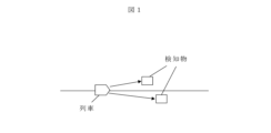
- FIG. 1 is a diagram showing an outline of a train control system according to an embodiment of the invention.
- FIG. 2 is a diagram showing an example of the configuration of the on-board control device 201 mounted on the train 101, which is a component of the train control system according to the embodiment.
- the train 101 is equipped with an onboard control device 201 and a sensor 205 .
- Sensors 205 are used to detect objects 102 along the train track. Detection of the detection object 102 is performed by the sensor control unit 204 .
- the sensor 205 is assumed to be an image pickup device such as a camera, but may be a sensor using millimeter wave radar, laser radar, or the like.
- the detected object DB 203 is a database that stores a list of detected objects 102 that can be detected at the position of the train 101 .
- the detected object DB 203 may be created separately for each sensor.
- the detected object DB 203 may be of one type.
- the sensor abnormality determination unit 202 receives the train position from the train control unit 206, refers to the detected object DB 203 with the received train position, and obtains a list of detected objects 102 that can be detected at the current position.
- the sensor abnormality determination unit 202 compares the list obtained from the detected object DB 203 with the detected object 102 output from the sensor control unit 204 . According to this comparison, if there is a shortage in the detected object 102, the missing object 102 is determined as an undetected object, and if this undetected object satisfies the abnormality determination condition, the sensor Judged as abnormal. That is, the sensor abnormality determination unit 202 determines sensor abnormality based on the data stored in the detected object DB 203 .
- FIG. 3 is a diagram showing an example of the configuration of data stored in the detected object DB 203. As shown in FIG. Since it is assumed that detectable objects 102 differ between inbound trains and outbound trains, detectable object DBs 203 are created for inbound trains and outbound trains. Here, FIG. 3 shows an example of the detected object DB 203 in the case of going down.
- the detected object DB 203 has position, detection distance and weight data for each type of the detected object 102 .
- the position indicates the distance in kilometers from the base point where the detected object 102 is located.
- the detection distance indicates the distance at which the detection object 102 can be detected from the position of the train.
- the detectable range of the “pillar” shown in FIG. 3 is 250m to 300m in kilometers.
- a weight is set for each detected object 102 .
- a maximum and a minimum are defined for the weight, and the weight varies depending on the distance to the detection object 102 within the range from the minimum to the maximum, and becomes maximum when the object is closest. For example, in the case of the "pillar" shown in FIG. 3, the weight is 0.1 at the point of 250 m in kilometers, and the weight is 0.5 at the point of 300 m in kilometers.
- the distance between the maximum and the minimum may be interpolated according to the characteristics of the sensor 205. For example, linear interpolation may be performed according to the distance.
- the weight is determined by the detection rate of each detected object 102 in each sensor, and when the detection rate is high, the weight is also set large. By setting the weights in this way, when the detection rate is low, even if there is no abnormality in the sensor 205, even if the detected object 102 is overlooked due to the influence of the surrounding environment, it is not immediately determined that the sensor is abnormal. Therefore, it is possible to improve the stability of train operation.
- the weight may be determined according to the importance of the detected object 102 to the safety of train running. For example, the "traffic signal" shown in FIG. 3 is important for the safety of train running, so a large weight may be set for it. If the weight of the detected object 102 is to be constant regardless of the distance, the maximum value and the minimum value of the weight should be set to the same value.
- the sensor abnormality determination unit 202 refers to the detected object DB 203, compares the detected object 102 detectable at the current position with the detected object 102 detected by the sensor control unit 204, A detection object 102 of detection is extracted.
- the sensor abnormality determination unit 202 calculates the weight of each of the extracted undetected objects 102, and adds up the calculated weights to calculate an abnormality detection index.
- the abnormality detection index is 1 or more, it is determined that the sensor is abnormal. For example, at a point of 300 m in kilometers, if neither the "pole" nor the "traffic light” shown in Fig. 3 can be detected, the maximum weight of the pole is 0.5, and the weight of the traffic light is 0.8 when linearly interpolated. Therefore, when the total is 1.3, it is determined that the sensor is abnormal. If one of them can be detected, it is not determined that the sensor is abnormal.
- the sensor abnormality determination unit 202 accumulates the abnormality detection index in time series. When an undetected object 102 is present and the train passes the position of the detected object 102, the detected object 102 does not exist in front of the train, so it is no longer determined as an undetected object 102. - ⁇ However, from the viewpoint of determining sensor abnormality, the fact that the object 102 has not been detected should be considered as a weight.
- the sensor abnormality determination unit 202 detects a new detected object 102 in the detected object DB 203 without resetting the abnormality detection index every cycle, the sensor is normal because the new detected object 102 is detected. Since it can be determined that there is, the anomaly detection index is reset to 0.
- the anomaly detection index is not reset, and the maximum weight of the undetected detected object 102 remains in the anomaly detection index. For example, assuming that a plurality of objects 102 to be detected under the same conditions as the “column” shown in FIG. I judge. However, if one pillar is detected and the next one cannot be detected repeatedly, the anomaly detection index is reset to 0 each time it is detected. 0.5, so it is not determined that the sensor is abnormal.
- the abnormality detection index is calculated for each sensor.
- the object 102 that can always be detected may be a rail on a track.
- the rail shape data is stored in the detected object DB 203 and it is determined whether the detected rail shape matches the rail shape in the detected object DB 203 .
- the configuration of the detected object DB 203 can be the same as the configuration shown in FIG.
- a change point of the rail shape that is, a change point of a straight line and a curve is set as a position, a detection distance that can detect the change point is set, and a weight is set using the detection rate of each rail shape.
- FIG. 4 is a diagram showing an example of the detected object DB 203 when the rail shape is used as the detected object.
- FIG. 4 shows that the straight section of the rail is 300 m to 500 m in kilometer, and that the rail shape is straight can be detected from a point 300 m before entering the straight section. After entering the straight section beyond the point of 300 m in kilometers, the maximum weight is applied for recognition of the straight line since it is within the section.
- the weight of each rail shape may be determined by the detection rate of the rail shape. For example, if a curve has a small radius, it is easy to recognize that it is a curve and the detection rate is high, so a large weight may be set.
- it may be configured to increase the weight of the detected object located within the vehicle limit in front of the train in the curved section.
- FIG. 5 is a diagram showing an example of a flowchart of processing for sensor abnormality detection by the sensor abnormality determination unit 202. As shown in FIG. If there are multiple sensors 205, the flowchart shown in FIG. 5 is executed for each sensor. The sensor abnormality determination unit 202 periodically executes the process of the flowchart shown in FIG. The processing mode of each step will be described below. Although the main body of processing in each step is the sensor abnormality determination unit 202, the description of the main body will be omitted below.
- the sensor abnormality determination unit 202 acquires a list of detected objects 102 currently detected by the sensor 205 from the sensor control unit 204 .
- the sensor abnormality determination unit 202 compares the list of detected objects 102 acquired in step 501 with the list of previously detected detected objects 102, and determines whether or not a new detected object 102 has been detected. If detected (Yes), go to step 503 to reset the anomaly detection index. If not detected (No), go to step 504 because there is no need to reset the anomaly detection index.
- the sensor abnormality determination unit 202 refers to the detected object DB 203 using the current train position acquired from the train control unit 206, and creates a list of detected objects 102 that can be detected at the current position.
- the sensor abnormality determination unit 202 compares the list of detected objects 102 acquired in step 501 with the list of detectable detected objects 102 created in step 504, and detects undetected detected objects 102, that is, detectable detected objects 102 but not in the list of detected objects 102 detected by the sensor 205 is determined. If so (Yes), go to step 506 to update the anomaly detection index for undetected objects 102 . If not (No), the process proceeds to step 508 because there is no need to update the anomaly detection index.
- the sensor abnormality determination unit 202 updates the abnormality detection index for the undetected object 102 .
- the weight of the undetected detection object 102 is calculated according to the current position of the train.
- the anomaly detection index is updated by adding the calculated weight as it is to the anomaly detection index in the case of a new detected object that has not been detected so far, that is, the detected object that was not previously included in the detectable list.
- the difference between the weight at the previous position and the weight at the current position is calculated, and only this difference is added to the abnormality detection index.
- Step 507 The sensor abnormality determination unit 202 determines whether or not the abnormality detection index has been updated in step 506 for all the detected objects 102 determined to be undetected in step 505 . If there is a remaining undetected object 102 (Yes), the process of step 506 is executed for the object 102 concerned. If there is no remaining undetected object 102 (No), the process proceeds to step 508 because updating of the anomaly detection index is completed.
- the sensor abnormality determination unit 202 determines whether or not the abnormality detection index is smaller than one. If it is 1 or more (Yes), the process proceeds to step 509 to determine that the sensor is abnormal. If it is less than 1 (No), it is determined that there is no sensor abnormality, and the process ends.
- Step 509> It is determined that a sensor abnormality has been detected, and predetermined abnormality processing is executed.
- the abnormality processing for example, when train running is disturbed, brake output may be performed, and when train operation can be continued, only warning output may be performed.
- the contents of the abnormality processing may be determined in advance in consideration of the degree of importance of the sensor that detected the abnormality.
- the performance of the sensor deteriorates due to the surrounding environment over a wide area, for example, when dense fog occurs over a wide area, even if the technology of the present invention is applied, the performance of the sensor does not deteriorate due to the surrounding environment. It may be judged as abnormal.
Landscapes
- Engineering & Computer Science (AREA)
- Mechanical Engineering (AREA)
- Health & Medical Sciences (AREA)
- Biomedical Technology (AREA)
- General Health & Medical Sciences (AREA)
- Life Sciences & Earth Sciences (AREA)
- Sustainable Development (AREA)
- Sustainable Energy (AREA)
- Power Engineering (AREA)
- Transportation (AREA)
- Train Traffic Observation, Control, And Security (AREA)
- Electric Propulsion And Braking For Vehicles (AREA)
Priority Applications (3)
| Application Number | Priority Date | Filing Date | Title |
|---|---|---|---|
| US18/844,381 US20250229812A1 (en) | 2021-12-16 | 2022-11-15 | Train control system and train control method |
| EP22907109.7A EP4450364A4 (en) | 2021-12-16 | 2022-11-15 | TRAIN CONTROL SYSTEM AND TRAIN CONTROL METHOD |
| AU2022412197A AU2022412197B2 (en) | 2021-12-16 | 2022-11-15 | Train control system and train control method |
Applications Claiming Priority (2)
| Application Number | Priority Date | Filing Date | Title |
|---|---|---|---|
| JP2021203982A JP7790957B2 (ja) | 2021-12-16 | 2021-12-16 | 列車制御システムおよび列車制御方法 |
| JP2021-203982 | 2021-12-16 |
Publications (1)
| Publication Number | Publication Date |
|---|---|
| WO2023112578A1 true WO2023112578A1 (ja) | 2023-06-22 |
Family
ID=86774010
Family Applications (1)
| Application Number | Title | Priority Date | Filing Date |
|---|---|---|---|
| PCT/JP2022/042327 Ceased WO2023112578A1 (ja) | 2021-12-16 | 2022-11-15 | 列車制御システムおよび列車制御方法 |
Country Status (5)
| Country | Link |
|---|---|
| US (1) | US20250229812A1 (https=) |
| EP (1) | EP4450364A4 (https=) |
| JP (1) | JP7790957B2 (https=) |
| AU (1) | AU2022412197B2 (https=) |
| WO (1) | WO2023112578A1 (https=) |
Cited By (1)
| Publication number | Priority date | Publication date | Assignee | Title |
|---|---|---|---|---|
| US20240034371A1 (en) * | 2019-10-18 | 2024-02-01 | Hitachi, Ltd. | Sensor performance evaluation system and method, and automatic driving system |
Families Citing this family (2)
| Publication number | Priority date | Publication date | Assignee | Title |
|---|---|---|---|---|
| JP2025023438A (ja) * | 2023-08-04 | 2025-02-17 | 株式会社日立製作所 | センサ診断システムおよびセンサ診断方法 |
| CN117523318B (zh) * | 2023-12-26 | 2024-04-16 | 宁波微科光电股份有限公司 | 一种抗光干扰的地铁屏蔽门异物检测方法、装置及介质 |
Citations (4)
| Publication number | Priority date | Publication date | Assignee | Title |
|---|---|---|---|---|
| JP2013253847A (ja) * | 2012-06-06 | 2013-12-19 | Hitachi Ltd | 故障確率算出装置及び故障確率算出方法並びに鉄道保守システム |
| JP2014176233A (ja) * | 2013-03-11 | 2014-09-22 | Railway Technical Research Institute | 複合事象発生時における異常時情報提示方法 |
| US20210094595A1 (en) * | 2019-04-12 | 2021-04-01 | Thales Management & Services Deutschland Gmbh | Method for safely and autonomously determining the position information of a train on a track |
| JP2021069162A (ja) * | 2019-10-18 | 2021-04-30 | 株式会社日立製作所 | センサ性能評価システム及び方法、並びに、自動運転システム |
Family Cites Families (4)
| Publication number | Priority date | Publication date | Assignee | Title |
|---|---|---|---|---|
| DE102006007788A1 (de) * | 2006-02-20 | 2007-08-30 | Siemens Ag | Verfahren zur rechnergestützten Überwachung des Betriebs eines einen vorgegebenen Streckenverlauf fahrenden Fahrzeugs, insbesondere eines spurgebundenen Schienenfahrzeugs |
| US10466709B2 (en) * | 2013-11-08 | 2019-11-05 | Hitachi, Ltd. | Autonomous driving vehicle and autonomous driving system |
| US9796400B2 (en) * | 2013-11-27 | 2017-10-24 | Solfice Research, Inc. | Real time machine vision and point-cloud analysis for remote sensing and vehicle control |
| WO2019020349A1 (de) * | 2017-07-27 | 2019-01-31 | Siemens Aktiengesellschaft | Überwachen von sensordaten und odometriedaten eines schienenfahrzeugs auf basis von kartendaten |
-
2021
- 2021-12-16 JP JP2021203982A patent/JP7790957B2/ja active Active
-
2022
- 2022-11-15 EP EP22907109.7A patent/EP4450364A4/en active Pending
- 2022-11-15 AU AU2022412197A patent/AU2022412197B2/en active Active
- 2022-11-15 WO PCT/JP2022/042327 patent/WO2023112578A1/ja not_active Ceased
- 2022-11-15 US US18/844,381 patent/US20250229812A1/en active Pending
Patent Citations (4)
| Publication number | Priority date | Publication date | Assignee | Title |
|---|---|---|---|---|
| JP2013253847A (ja) * | 2012-06-06 | 2013-12-19 | Hitachi Ltd | 故障確率算出装置及び故障確率算出方法並びに鉄道保守システム |
| JP2014176233A (ja) * | 2013-03-11 | 2014-09-22 | Railway Technical Research Institute | 複合事象発生時における異常時情報提示方法 |
| US20210094595A1 (en) * | 2019-04-12 | 2021-04-01 | Thales Management & Services Deutschland Gmbh | Method for safely and autonomously determining the position information of a train on a track |
| JP2021069162A (ja) * | 2019-10-18 | 2021-04-30 | 株式会社日立製作所 | センサ性能評価システム及び方法、並びに、自動運転システム |
Cited By (2)
| Publication number | Priority date | Publication date | Assignee | Title |
|---|---|---|---|---|
| US20240034371A1 (en) * | 2019-10-18 | 2024-02-01 | Hitachi, Ltd. | Sensor performance evaluation system and method, and automatic driving system |
| US12384434B2 (en) * | 2019-10-18 | 2025-08-12 | Hitachi, Ltd. | Sensor performance evaluation system and method, and automatic driving system |
Also Published As
| Publication number | Publication date |
|---|---|
| JP2023089473A (ja) | 2023-06-28 |
| JP7790957B2 (ja) | 2025-12-23 |
| EP4450364A4 (en) | 2026-03-04 |
| AU2022412197A1 (en) | 2024-07-11 |
| AU2022412197B2 (en) | 2025-08-14 |
| EP4450364A1 (en) | 2024-10-23 |
| US20250229812A1 (en) | 2025-07-17 |
Similar Documents
| Publication | Publication Date | Title |
|---|---|---|
| WO2023112578A1 (ja) | 列車制御システムおよび列車制御方法 | |
| US9428057B2 (en) | Information provision device for use in vehicle | |
| JP6438108B2 (ja) | 安全速度情報生成装置、安全速度生成方法、及びプログラム | |
| US20180312161A1 (en) | Vehicle travel control device | |
| WO2019155569A1 (ja) | 障害物検出装置および障害物検出方法 | |
| US11506510B1 (en) | Method and system for identifying confidence level of autonomous driving system | |
| JP7146686B2 (ja) | 列車制御システム及び当該システムを搭載した鉄道車両 | |
| US11209827B2 (en) | Method and electronic device for controlling the speed of an autonomous vehicle, related computer program, autonomous vehicle and monitoring platform | |
| EP3984847A1 (en) | Vehicle and driving control method thereof | |
| US20240400042A1 (en) | Autonomous Vehicle And Method Of Controlling | |
| CN115320592B (zh) | 车速规划方法、装置、芯片、终端、计算机设备及介质 | |
| JP5499815B2 (ja) | 走行道路推定システム | |
| JP2023064792A (ja) | 車両の走行制御処理システム | |
| KR20230042051A (ko) | 적어도 부분적으로 자동화된 모바일 플랫폼을 위한 내비게이션 맵 | |
| CN117341766A (zh) | 限速确定、列车控制方法、装置、计算机设备和存储介质 | |
| CN109625035B (zh) | 隧道地上混合线路的列车运行模式处理方法及装置 | |
| WO2025032945A1 (ja) | センサ診断システムおよびセンサ診断方法 | |
| CN116045992B (zh) | 自动驾驶车辆的导航方法、装置及电子设备、存储介质 | |
| US12315269B2 (en) | Method and device for determining reliability of visual detection | |
| US20250115280A1 (en) | Offboard infrastructure to augment vehicle systems | |
| JP7738504B2 (ja) | 車載器、逆走検知システム、逆走検知方法、およびプログラム | |
| JP7288380B2 (ja) | データ記録装置及びデータ記録方法 | |
| WO2022220279A1 (ja) | 鉄道車両運転制御装置 | |
| JP2025039176A (ja) | 走行パターン生成装置、車両及び走行パターン生成方法 | |
| WO2026053304A1 (ja) | 車両制御方法、及び車両制御装置 |
Legal Events
| Date | Code | Title | Description |
|---|---|---|---|
| 121 | Ep: the epo has been informed by wipo that ep was designated in this application |
Ref document number: 22907109 Country of ref document: EP Kind code of ref document: A1 |
|
| WWE | Wipo information: entry into national phase |
Ref document number: 2022412197 Country of ref document: AU Ref document number: AU2022412197 Country of ref document: AU |
|
| WWE | Wipo information: entry into national phase |
Ref document number: 2022907109 Country of ref document: EP |
|
| NENP | Non-entry into the national phase |
Ref country code: DE |
|
| ENP | Entry into the national phase |
Ref document number: 2022907109 Country of ref document: EP Effective date: 20240716 |
|
| WWP | Wipo information: published in national office |
Ref document number: 18844381 Country of ref document: US |