WO2023112463A1 - 空間浮遊映像情報表示システム - Google Patents
空間浮遊映像情報表示システム Download PDFInfo
- Publication number
- WO2023112463A1 WO2023112463A1 PCT/JP2022/038557 JP2022038557W WO2023112463A1 WO 2023112463 A1 WO2023112463 A1 WO 2023112463A1 JP 2022038557 W JP2022038557 W JP 2022038557W WO 2023112463 A1 WO2023112463 A1 WO 2023112463A1
- Authority
- WO
- WIPO (PCT)
- Prior art keywords
- floating image
- user
- information display
- display system
- spatial
- Prior art date
- Legal status (The legal status is an assumption and is not a legal conclusion. Google has not performed a legal analysis and makes no representation as to the accuracy of the status listed.)
- Ceased
Links
Images












Classifications
-
- G—PHYSICS
- G02—OPTICS
- G02B—OPTICAL ELEMENTS, SYSTEMS OR APPARATUS
- G02B30/00—Optical systems or apparatus for producing three-dimensional [3D] effects, e.g. stereoscopic images
- G02B30/50—Optical systems or apparatus for producing three-dimensional [3D] effects, e.g. stereoscopic images the image being built up from image elements distributed over a three-dimensional [3D] volume, e.g. voxels
- G02B30/56—Optical systems or apparatus for producing three-dimensional [3D] effects, e.g. stereoscopic images the image being built up from image elements distributed over a three-dimensional [3D] volume, e.g. voxels by projecting aerial or floating images
-
- G—PHYSICS
- G06—COMPUTING OR CALCULATING; COUNTING
- G06F—ELECTRIC DIGITAL DATA PROCESSING
- G06F1/00—Details not covered by groups G06F3/00 - G06F13/00 and G06F21/00
- G06F1/16—Constructional details or arrangements
- G06F1/1613—Constructional details or arrangements for portable computers
- G06F1/1633—Constructional details or arrangements of portable computers not specific to the type of enclosures covered by groups G06F1/1615 - G06F1/1626
- G06F1/1637—Details related to the display arrangement, including those related to the mounting of the display in the housing
- G06F1/1639—Details related to the display arrangement, including those related to the mounting of the display in the housing the display being based on projection
-
- G—PHYSICS
- G06—COMPUTING OR CALCULATING; COUNTING
- G06F—ELECTRIC DIGITAL DATA PROCESSING
- G06F1/00—Details not covered by groups G06F3/00 - G06F13/00 and G06F21/00
- G06F1/26—Power supply means, e.g. regulation thereof
- G06F1/32—Means for saving power
- G06F1/3203—Power management, i.e. event-based initiation of a power-saving mode
- G06F1/3206—Monitoring of events, devices or parameters that trigger a change in power modality
- G06F1/3231—Monitoring the presence, absence or movement of users
-
- G—PHYSICS
- G06—COMPUTING OR CALCULATING; COUNTING
- G06F—ELECTRIC DIGITAL DATA PROCESSING
- G06F1/00—Details not covered by groups G06F3/00 - G06F13/00 and G06F21/00
- G06F1/26—Power supply means, e.g. regulation thereof
- G06F1/32—Means for saving power
- G06F1/3203—Power management, i.e. event-based initiation of a power-saving mode
- G06F1/3234—Power saving characterised by the action undertaken
- G06F1/325—Power saving in peripheral device
- G06F1/3265—Power saving in display device
-
- G—PHYSICS
- G06—COMPUTING OR CALCULATING; COUNTING
- G06F—ELECTRIC DIGITAL DATA PROCESSING
- G06F3/00—Input arrangements for transferring data to be processed into a form capable of being handled by the computer; Output arrangements for transferring data from processing unit to output unit, e.g. interface arrangements
- G06F3/01—Input arrangements or combined input and output arrangements for interaction between user and computer
-
- G—PHYSICS
- G06—COMPUTING OR CALCULATING; COUNTING
- G06F—ELECTRIC DIGITAL DATA PROCESSING
- G06F3/00—Input arrangements for transferring data to be processed into a form capable of being handled by the computer; Output arrangements for transferring data from processing unit to output unit, e.g. interface arrangements
- G06F3/01—Input arrangements or combined input and output arrangements for interaction between user and computer
- G06F3/011—Arrangements for interaction with the human body, e.g. for user immersion in virtual reality
-
- G—PHYSICS
- G06—COMPUTING OR CALCULATING; COUNTING
- G06F—ELECTRIC DIGITAL DATA PROCESSING
- G06F3/00—Input arrangements for transferring data to be processed into a form capable of being handled by the computer; Output arrangements for transferring data from processing unit to output unit, e.g. interface arrangements
- G06F3/01—Input arrangements or combined input and output arrangements for interaction between user and computer
- G06F3/017—Gesture based interaction, e.g. based on a set of recognized hand gestures
-
- G—PHYSICS
- G06—COMPUTING OR CALCULATING; COUNTING
- G06F—ELECTRIC DIGITAL DATA PROCESSING
- G06F3/00—Input arrangements for transferring data to be processed into a form capable of being handled by the computer; Output arrangements for transferring data from processing unit to output unit, e.g. interface arrangements
- G06F3/01—Input arrangements or combined input and output arrangements for interaction between user and computer
- G06F3/02—Input arrangements using manually operated switches, e.g. using keyboards or dials
-
- G—PHYSICS
- G06—COMPUTING OR CALCULATING; COUNTING
- G06F—ELECTRIC DIGITAL DATA PROCESSING
- G06F3/00—Input arrangements for transferring data to be processed into a form capable of being handled by the computer; Output arrangements for transferring data from processing unit to output unit, e.g. interface arrangements
- G06F3/01—Input arrangements or combined input and output arrangements for interaction between user and computer
- G06F3/048—Interaction techniques based on graphical user interfaces [GUI]
- G06F3/0481—Interaction techniques based on graphical user interfaces [GUI] based on specific properties of the displayed interaction object or a metaphor-based environment, e.g. interaction with desktop elements like windows or icons, or assisted by a cursor's changing behaviour or appearance
- G06F3/04815—Interaction with a metaphor-based environment or interaction object displayed as three-dimensional [3D], e.g. changing the user viewpoint with respect to the environment or object
-
- G—PHYSICS
- G06—COMPUTING OR CALCULATING; COUNTING
- G06F—ELECTRIC DIGITAL DATA PROCESSING
- G06F3/00—Input arrangements for transferring data to be processed into a form capable of being handled by the computer; Output arrangements for transferring data from processing unit to output unit, e.g. interface arrangements
- G06F3/01—Input arrangements or combined input and output arrangements for interaction between user and computer
- G06F3/048—Interaction techniques based on graphical user interfaces [GUI]
- G06F3/0481—Interaction techniques based on graphical user interfaces [GUI] based on specific properties of the displayed interaction object or a metaphor-based environment, e.g. interaction with desktop elements like windows or icons, or assisted by a cursor's changing behaviour or appearance
- G06F3/0482—Interaction with lists of selectable items, e.g. menus
-
- G—PHYSICS
- G06—COMPUTING OR CALCULATING; COUNTING
- G06F—ELECTRIC DIGITAL DATA PROCESSING
- G06F3/00—Input arrangements for transferring data to be processed into a form capable of being handled by the computer; Output arrangements for transferring data from processing unit to output unit, e.g. interface arrangements
- G06F3/01—Input arrangements or combined input and output arrangements for interaction between user and computer
- G06F3/048—Interaction techniques based on graphical user interfaces [GUI]
- G06F3/0484—Interaction techniques based on graphical user interfaces [GUI] for the control of specific functions or operations, e.g. selecting or manipulating an object, an image or a displayed text element, setting a parameter value or selecting a range
- G06F3/04842—Selection of displayed objects or displayed text elements
-
- G—PHYSICS
- G06—COMPUTING OR CALCULATING; COUNTING
- G06F—ELECTRIC DIGITAL DATA PROCESSING
- G06F3/00—Input arrangements for transferring data to be processed into a form capable of being handled by the computer; Output arrangements for transferring data from processing unit to output unit, e.g. interface arrangements
- G06F3/01—Input arrangements or combined input and output arrangements for interaction between user and computer
- G06F3/048—Interaction techniques based on graphical user interfaces [GUI]
- G06F3/0487—Interaction techniques based on graphical user interfaces [GUI] using specific features provided by the input device, e.g. functions controlled by the rotation of a mouse with dual sensing arrangements, or of the nature of the input device, e.g. tap gestures based on pressure sensed by a digitiser
- G06F3/0488—Interaction techniques based on graphical user interfaces [GUI] using specific features provided by the input device, e.g. functions controlled by the rotation of a mouse with dual sensing arrangements, or of the nature of the input device, e.g. tap gestures based on pressure sensed by a digitiser using a touch-screen or digitiser, e.g. input of commands through traced gestures
- G06F3/04883—Interaction techniques based on graphical user interfaces [GUI] using specific features provided by the input device, e.g. functions controlled by the rotation of a mouse with dual sensing arrangements, or of the nature of the input device, e.g. tap gestures based on pressure sensed by a digitiser using a touch-screen or digitiser, e.g. input of commands through traced gestures for inputting data by handwriting, e.g. gesture or text
-
- G—PHYSICS
- G06—COMPUTING OR CALCULATING; COUNTING
- G06F—ELECTRIC DIGITAL DATA PROCESSING
- G06F9/00—Arrangements for program control, e.g. control units
- G06F9/06—Arrangements for program control, e.g. control units using stored programs, i.e. using an internal store of processing equipment to receive or retain programs
- G06F9/44—Arrangements for executing specific programs
- G06F9/451—Execution arrangements for user interfaces
- G06F9/453—Help systems
-
- G—PHYSICS
- G06—COMPUTING OR CALCULATING; COUNTING
- G06V—IMAGE OR VIDEO RECOGNITION OR UNDERSTANDING
- G06V40/00—Recognition of biometric, human-related or animal-related patterns in image or video data
- G06V40/10—Human or animal bodies, e.g. vehicle occupants or pedestrians; Body parts, e.g. hands
-
- H—ELECTRICITY
- H04—ELECTRIC COMMUNICATION TECHNIQUE
- H04N—PICTORIAL COMMUNICATION, e.g. TELEVISION
- H04N13/00—Stereoscopic video systems; Multi-view video systems; Details thereof
- H04N13/30—Image reproducers
- H04N13/346—Image reproducers using prisms or semi-transparent mirrors
-
- H—ELECTRICITY
- H04—ELECTRIC COMMUNICATION TECHNIQUE
- H04N—PICTORIAL COMMUNICATION, e.g. TELEVISION
- H04N13/00—Stereoscopic video systems; Multi-view video systems; Details thereof
- H04N13/30—Image reproducers
- H04N13/398—Synchronisation thereof; Control thereof
Definitions
- the present invention relates to a spatial floating image information display system.
- Patent Document 1 Japanese Patent Application Laid-Open No. 2019-128722
- the spatially floating image by the spatially floating image information display system as a user interface or man-machine interface that can be operated by the user, we would like to realize an interface that is excellent in usability and convenience.
- the user can intuitively grasp the operation method, etc.
- devices generally called "kiosk terminals” we would like to provide a user interface that is excellent in usability and convenience by means of spatially floating images.
- the user interface formed by floating images in space for example, the operation menu such as push buttons
- the operation menu such as push buttons
- the risk of contact infection is minimized. It has the advantage of being able to limit We would like to realize a spatially floating image information display system that makes the most of these advantages.
- a spatially floating image information display system is a spatially floating image information display system that forms a spatially floating image in the air.
- retroreflecting member for forming the spatially floating image in the air by retroreflecting the image light
- a sensing system including a sensor for detecting a user's operation on the spatially floating image
- the image display device and a housing provided with the retroreflective member, and a control device that executes a predetermined process based on the detected operation, and when it is detected that the user approaches the housing , the image of the object is displayed as the spatial floating image.
- the space floating image information display system is highly user-friendly and convenient, and provides an interface and necessary information using a space floating image suitable for users such as kiosk terminals. can provide. Problems, configurations, effects, etc. other than those described above will be described in the mode for carrying out the invention.
- FIG. 1 is a diagram showing an example of a usage pattern of a spatially floating image information display system according to an embodiment
- FIG. 1 is a diagram showing an example of an internal configuration of a spatial floating image information display system according to an embodiment
- FIG. 1 is a diagram showing an example of a configuration of main parts and a configuration of a retroreflection part of a spatially floating image information display system according to an embodiment
- FIG. 10 is a diagram showing another example of the configuration of the main part and the configuration of the retroreflection part of the spatially floating image information display system according to one embodiment
- FIG. 4 is a perspective view showing an example of arrangement of members that block extraordinary rays generated by retroreflection according to an embodiment.
- FIG. 4 is a cross-sectional view showing an example of arrangement of a member that blocks an extraordinary ray generated by retroreflection according to an embodiment
- FIG. 2 is an explanatory diagram of a first sensing technique used in a spatially floating image information display system according to an embodiment
- FIG. 10 is an explanatory diagram of a second sensing technique used in the spatially floating image information display system according to one embodiment
- FIG. 4 is an explanatory diagram of the operation and device of a sensing system used in the spatially floating image information display system according to one embodiment; It is a figure which shows the characteristic of the spectral irradiance of sunlight.
- FIG. 2 is an explanatory diagram of a first sensing technique used in a spatially floating image information display system according to an embodiment
- FIG. 10 is an explanatory diagram of a second sensing technique used in the spatially floating image information display system according to one embodiment
- FIG. 4 is an explanatory diagram of the operation and device of a sensing system used in the spatially floating image
- FIG. 10 is a diagram showing reflection characteristics of polarized light incident on a medium with a refractive index of 1.5 with respect to the incident angle of light;
- FIG. 10 is an explanatory diagram of a technique for inputting/drawing characters and the like in a spatially floating image according to an embodiment;
- 1 is a diagram showing the main configuration of a spatially floating image information display system according to an embodiment of the present invention;
- FIG. 10 is a diagram showing the main configuration of another spatially floating image information display system according to an embodiment of the present invention; It is a figure which shows an example of a kiosk terminal.
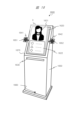
- 1 is a diagram showing an appearance example of a kiosk terminal according to an example (Embodiment 1);
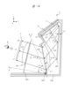
- FIG. 3 is a diagram showing an example of a cross-sectional structure of a kiosk terminal according to Embodiment 1;
- FIG. FIG. 10 is a diagram showing an appearance example of a kiosk terminal according to an example (Embodiment 2);
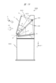
- FIG. 10 is a diagram illustrating an example of a cross-sectional structure of a kiosk terminal according to Embodiment 2;
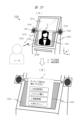
- FIG. 10 is a diagram showing a display example of a kiosk terminal according to an example (Embodiment 3);
- FIG. 10 is a diagram showing a first operation flow of a kiosk terminal according to Embodiment 3;
- FIG. 12 is a diagram showing a second operation flow of the kiosk terminal according to Embodiment 3;
- FIG. 10 is a diagram showing cooperative operation between a kiosk terminal and a mobile terminal according to an example (Embodiment 4);
- FIG. 13 is a diagram showing an example of sign operation/display at a kiosk terminal according to an example (Embodiment 5);
- FIG. 10 is a diagram showing a display example of a kiosk terminal according to a modification of the third embodiment;
- FIG. 3 is a cross-sectional view showing a specific configuration example of a light source device; It is a structural diagram showing a specific configuration example of a light source device. It is a figure which shows the specific structural example of the light source device of another system.
- FIG. 10 is a diagram showing an appearance example of a vending machine according to an example (another embodiment);
- the main body as hardware for them is the processor or the controller composed of the processor etc. , devices, computers, systems, etc.
- a computer executes processing according to a program read out on a memory by a processor while appropriately using resources such as a memory and a communication interface.
- the processor is composed of, for example, a CPU (Central Processing Unit), a semiconductor device such as a GPU, or the like.
- a processor is composed of devices and circuits capable of performing predetermined operations.
- the processing can be implemented not only by software program processing but also by dedicated circuits. FPGA (field-programmable gate array), ASIC (application specific integrated circuit), CPLD (Complex Programmable Logic Device), etc. can be applied to the dedicated circuit.
- the program may be pre-installed as data on the target computer, or may be distributed as data from the program source to the target computer.
- the program source may be a program distribution server on a communication network, or a non-transitory computer-readable storage medium (eg, memory card).
- a program may consist of a plurality of modules.
- a computer system may be configured by a plurality of devices.
- the computer system may be configured as a client-server system, a cloud computing system, or the like.
- Various types of data and information are composed of, for example, structures such as tables and lists, but are not limited to this. Expressions such as identification information, identifier, ID (identification), name, number, etc. are interchangeable.
- a spatially floating image information display system (hereinafter sometimes simply referred to as a system) according to one embodiment first eliminates ghost images that significantly reduce the visibility of spatially floating images, and improves the brightness of spatially floating images. It has a configuration for improving visibility by A system according to one embodiment is applied to a kiosk terminal or the like, and provides a user interface such as an operation menu on a screen based on spatial floating images.
- the system of one embodiment first displays a concierge (such as a concierge image) as a predetermined human image on the screen of the floating image in space. may be listed) is displayed.
- the system greets, guides, explains, etc. to the user by means of a concierge of spatial floating images.
- the concierge image when the user approaches the spatially floating image or performs an operation on the spatially floating image, the concierge image is automatically displayed using a predetermined operation menu or the like, for example, a plurality of The operation menu screen has numeric buttons, option buttons, etc., and the buttons can be pressed.
- the system appropriately guides and explains the operation menu to the user by means of a concierge of floating images in space.
- the concierge guides the user through the operation menu in detail.
- the concierge guides the user through the operation menu in detail.
- the spatially floating image information display system of one embodiment has a function of identifying and specifying a user by, for example, face recognition using a camera.
- the system refers to user attribute information such as age and system usage history for users identified by the function.
- the system is controlled so as to change the method and content of the guidance by the concierge of the floating image in space according to the user's attribute.
- the spatially floating image information display system of one embodiment also provides a function that allows the user to input arbitrary characters and figures on the surface of the spatially floating image with fingers.
- the system detects the contact state of fingers on the plane of the floating image and draws the input lines on the plane of the floating image. The system takes this input line as the user's signature, for example.
- images floating in space and images displayed in the air may be expressed by the term “space floating image”.
- expressions such as “aerial image”, “aerial image”, “aerial floating image”, “aerial floating optical image of displayed image”, “aerial floating optical image of displayed image”, etc. may be used.
- space floating image mainly used in the description of the embodiments is used as a representative example of these terms.
- the present disclosure transmits an image by image light from a large-area image light source through a transparent member that partitions the space, such as the glass of a show window, and displays it inside or outside the store space as a floating image. It relates to a displayable information display system. The present disclosure also relates to a large-scale digital signage system configured using a plurality of such information display systems.
- the angle of divergence of the emitted image light is made small, that is, an acute angle, and furthermore, by aligning it with a specific polarized wave, only the regular reflected light is efficiently emitted to the retroreflective member (retroreflective member) or retroreflective plate. It can reflect well.
- the light utilization efficiency is high, and the ghost image that occurs in addition to the main space floating image, which has been a problem in the conventional retroreflection method, can be suppressed, and clear space floating can be obtained. You can get pictures.
- the apparatus including the light source of the present disclosure can provide a novel and highly usable spatial floating image information display system capable of significantly reducing power consumption.
- the technology of the present disclosure for example, it is possible to display a so-called unidirectional spatial floating image that is visible outside the vehicle through shield glass including the windshield, rear glass, and side glass of the vehicle.
- a spatial floating image information display system for vehicles can be provided.
- conventional spatial floating image information display systems combine organic EL panels and display panels (sometimes referred to as liquid crystal display panels, liquid crystal panels, etc.) as high-resolution color display image sources with retroreflective members.
- the image light is diffused over a wide angle. Therefore, when using the retroreflective member 2 in the first embodiment constituted by the polyhedron shown in FIG.
- image light obliquely incident on the retroreflective member 2 (retroreflective portion 2a) shown in FIG. 3C causes a ghost image. As a result, the image quality of the spatially floating image is degraded.
- the conventional spatial floating image display device in addition to the normal spatial floating image, a plurality of ghost images corresponding to the number of reflecting surfaces are generated. As a result, the image floating in the same space, which is a ghost image, can be viewed by people other than the viewer, which poses a serious problem from the viewpoint of security.
- FIG. 1A shows an example of usage of the spatially floating image information display system of the embodiment, and shows an explanatory diagram of the overall configuration of the spatially floating image information display system.
- a show window (also referred to as window glass) 105 which is a translucent member (also referred to as a transparent member) such as glass, partitions the space.
- a spatially floating image can be displayed in one direction to the outside of the store space through such a transparent member.
- the image display device 10 light with a narrow-angle directional characteristic and a specific polarized wave is emitted from the image display device 10 as an image light beam.
- the emitted image light flux is once incident on the retroreflection member 2, retroreflected, transmitted through the window glass 105, and forms a space floating image (aerial image) 3, which is a real image, outside the store space.
- FIG. 1A the inside of the store inside the transparent member (here, the window glass) 105 is taken as the depth direction, and the outside of the window glass 105 (for example, the sidewalk) is shown in front.
- the video display device 10 includes a video display unit 1102 that displays an original image of an aerial image, a video control unit 1160 that converts the input video in accordance with the resolution of the panel, and video/audio signals for receiving/inputting video/audio signals. and a signal receiver 1130 .
- the video/audio signal receiving unit 1130 supports wired input signals through input interfaces such as HDMI (High-Definition Multimedia Interface) (registered trademark) and Wi-Fi (Wireless Fidelity) (registered trademark) and other wireless input signals.
- the video/audio signal reception unit 1130 can function independently as a video reception/display device.
- the video/audio signal receiving unit 1130 can display/output video/audio information from a tablet terminal, a smartphone, or the like.
- the video/audio signal receiving unit 1130 can be connected to a processor (arithmetic processing unit) such as a stick PC as necessary. Capabilities such as analysis processing can also be provided.
- FIG. 2 shows a functional block diagram of the spatial floating image information display system 1.
- the image display unit 1102 modulates light passing through the panel of the image display unit 1102 based on the image signal to generate an image.
- the video display unit 1102 may use a transmissive liquid crystal display panel, and in some cases, a reflective liquid crystal display panel that modulates light reflected on the panel based on a video signal, or a DMD panel (DMD: Digital Micromirror). Device (registered trademark) or the like.
- DMD Digital Micromirror
- the retroreflection unit 1101 retroreflects the light modulated by the image display unit 1102 .
- the light output to the outside of the spatially floating image information display system 1 forms the spatially floating image 3 .
- a light source 1105 generates light for the image display section 1102 .
- a solid-state light source such as an LED light source or a laser light source is used as the light source 1105 .
- the power supply 1106 converts AC current input from the outside into DC current to power the light source 1105 . In addition, power supply 1106 supplies the necessary DC current to each of the other units.
- the light guide 1104 guides the light generated by the light source 1105 and irradiates the image display section 1102 with the light.
- the combination of light guide 1104 and light source 1105 can also be called a backlight of image display section 1102 .
- Various methods can be considered for the combination of the light guide 1104 and the light source 1105 . A specific configuration example will be described later. Note that, as shown in FIG. 2, a portion composed of three parts, ie, the image display section 1102, the light guide 1104, and the light source 1105, is particularly referred to as the image display device 10.
- FIG. 2 a portion composed of three parts, ie, the image display section 1102, the light guide 1104, and the light source 1105, is particularly referred to as the image display device 10.
- the mid-air operation detection sensor 1351 detects an operation (also referred to as mid-air operation) of the floating image 3 by the user's fingers. It is a sensor that senses the range superimposed on .
- the aerial operation detection sensor 1351 can detect two-dimensional plane coordinates by using distance sensors using invisible light such as infrared rays, invisible light lasers, ultrasonic waves, or the like, as a specific sensor configuration. It may be configured. Further, the mid-air operation detection sensor 1351 may be configured as a ToF (Time of Flight) type LiDAR (Light Detection and Ranging), which will be described later.
- ToF Time of Flight
- LiDAR Light Detection and Ranging
- the mid-air operation detection unit 1350 acquires the sensing signal acquired by the mid-air operation detection sensor 1351, and based on this, determines whether or not the user's finger touches the floating image 3, and determines the position of the touch on the floating image 3. is calculated.
- the aerial operation detection unit 1350 may be configured by a circuit such as FPGA.
- the aerial operation detection sensor 1351 and the aerial operation detection unit 1350 may be configured to be incorporated in the spatial floating image information display system 1, but the spatial floating image information display system 1 It may be provided outside a separate body. When provided separately, it may be configured so that information or signals can be transmitted to the spatially floating image information display system 1 via a wired or wireless communication connection path or image signal transmission path. Both the aerial operation detection sensor 1351 and the aerial operation detection unit 1350 may be provided separately. In this case, it is possible to construct a system in which only the aerial operation detection function can be added as an option using the space floating image information display system 1 without the aerial operation detection function as the main body.
- the mid-air operation detection sensor 1351 may be provided separately, and the mid-air operation detection unit 1350 may be incorporated in the floating image information display system 1 . If it is desired to arrange the mid-air operation detection sensor 1351 more freely with respect to the installation position of the spatially floating image information display system 1, there is an advantage in the configuration in which only the mid-air operation detection sensor 1351 is separate.
- the imaging unit 1180 is a so-called camera having an image sensor, and images the space near the floating image 3 and/or the user's face, arms, fingers, and the like.
- the imaging unit 1180 may use a plurality of cameras or a camera with a depth sensor depending on the application.
- the imaging unit 1180 may be provided separately from the spatial floating image information display system 1 .
- the imaging unit 1180 detects a user's touch operation on the spatially floating image 3, in other words, an operation of touching the surface of the spatially floating image 3. Part 1350 may be assisted.
- the aerial operation detection sensor 1351 targets the plane to which the spatial floating image 3 belongs and is configured as an object intrusion sensor into the plane, an object (for example, a user's finger) that has not entered the plane is detected.
- the aerial operation detection sensor 1351 alone cannot detect how close it is to the plane.
- an object for example, a user's finger
- This calculated information can be used for various display controls in the spatial floating image 3 .
- the present system may be configured such that the aerial operation detection unit 1350 detects a user's touch operation on the floating image 3 based on the imaging result of the imaging unit 1180 without using the aerial operation detection sensor 1351. good.
- the image capturing unit 1180 may capture an image of the face of the user who operates the floating image 3, and the control unit 1110 may perform user identification/specification processing or user authentication processing based on the captured image. .
- the user who operates the floating image 3 may operate the floating image 3 in order to determine whether or not another person is standing around or behind the user who operates the floating image 3 and is peeking at the user's operation on the floating image 3.
- the imaging unit 1180 may be configured to capture an image including the surroundings of the user.
- the operation input unit 1107 is an operation button or a remote control light receiving unit, and inputs a signal related to a user's operation, which is different from the aerial operation for the spatial floating image 3 .
- the operation input unit 1107 may be used by an administrator of the spatially floating image information display system 1 to operate this system, apart from the above-described user who touch-operates the spatially floating image 3 .
- the video signal input unit 1131 has a function of connecting an external video output device and inputting video data.
- the audio signal input unit 1133 has a function of connecting an external audio output device and inputting audio data.
- audio signal output section 1140 has a function of outputting an audio signal based on audio data input to audio signal input section 1133 .
- the audio signal output unit 1140 may output an audio signal based on audio data such as numbers and character strings recorded in the storage unit 1170 in advance, and other operation sound and error warning sound data.
- the video signal input section 1131 and the audio signal input section 1133 are collectively referred to as the video/audio signal input section 1130 .
- the video signal input section 1131 and the audio signal input section 1133 may be configured individually, or may be combined into one.
- the audio signal output unit 1140 is connected to the speaker or the super-directional speaker 30.
- the audio signal output unit 1140 may be connected to a speaker that outputs audio in a normal audible band, but as in the case of the kiosk terminal described later, it is particularly necessary to consider security due to high secrecy. In some cases, it may be connected to a super-directional speaker so that it cannot be heard by anyone other than the user.
- a super-directional speaker is one in which only human ears existing in a specific limited spatial area can hear sound in the audible band, and those outside the specific spatial area can hear sound in the audible band. It is a speaker that has the characteristic that the voice cannot be heard.
- the super-directional speaker 30 is configured by, for example, arranging a plurality of ultrasonic output elements capable of generating ultrasonic signals of about 40 kHz on a plane. At this time, as the number of ultrasonic output elements used increases, the sound volume obtained by the super-directional speaker increases.
- the principle of a super-directional speaker will be briefly explained. As is well known, ultrasonic waves are more linear than sounds in the audible band (for example, human speech). Therefore, by using an ultrasonic signal of 40 kHz as a carrier and modulating the carrier with an audio signal in the audible band (for example, AM modulation), it is possible to make sounds audible only in a specific limited spatial region. becomes.
- the positions of the user's face and ears are specified, and according to the specified result, the output from the super-directional speaker 30 is used in the vicinity of the user's ears You can only hear audio.
- the phase (in other words, delay time) of the ultrasonic signal input to the ultrasonic output element that constitutes the super-directional speaker 30 the sound can be heard only in a specified limited spatial region.
- the phase in other words, delay time
- the ultrasonic output element that constitutes the super-directional speaker 30 the sound can be heard only in a specified limited spatial region.
- a plurality of ultrasonic output elements on, for example, a concave surface rather than on a flat surface, it is possible to make sounds audible only in a specific limited spatial region.
- the non-volatile memory 1108 stores various data used in the spatial floating image information display system 1.
- the data stored in the non-volatile memory 1108 includes data for various operations displayed as the spatial floating image 3, user interface image information such as icons and buttons, object data and layout information for user operation, and the like. may be included.
- a memory 1109 stores image data to be displayed as the spatial floating image 3 and control data for the apparatus.
- the control unit 1110 corresponds to the controller (in other words, control device) of the spatial floating image information display system 1, and controls the operation of each connected unit.
- the control unit 1110 includes a device such as a processor.
- the control unit 1110 executes processing according to a program read from the nonvolatile memory 1108 or storage unit 1170 to the memory 1109 or built-in memory. As a result, various functions are realized.
- the control unit 1110 may cooperate with a program stored in the memory 1109 to perform arithmetic processing based on information acquired from each connected unit.
- the control unit 1110 may be mounted using a microcomputer or the like inside the housing that constitutes the spatial floating image information display system 1, or may be connected/mounted outside the housing.
- the communication unit 1132 communicates with external devices, external servers, etc. via a wired or wireless communication interface.
- the communication unit 1132 transmits and receives video, image, audio, and various data through the communication.
- the storage unit 1170 records videos, images, sounds, various data, and the like.
- videos, images, sounds, various data, and the like may be recorded in the storage unit 1170 in advance at the time of product shipment.
- Videos, images, sounds, various data, and the like acquired from an external device, an external server, or the like via the communication unit 1132 may be recorded in the storage unit 1170 .
- Videos, images, various data, and the like recorded in the storage unit 1170 can be output as the space-floating video 3 via the video display unit 1102, the video display device 10, and the retroreflection unit 1101.
- Data such as icons, buttons, and objects for user operation displayed as a user interface (including operation menus and concierge images to be described later) on the floating image 3, and data constituting the concierge image are also stored in the storage unit 1170. It may be included in the video or image data to be recorded. In addition, information such as operation menus such as icons, buttons, and objects displayed as a user interface on the floating image 3, layout information of the concierge, and various metadata related to the operation menus and the concierge are included in various data recorded in the storage unit 1170. may be included. Also, audio data for the concierge of the spatial floating image 3 to output audio may be recorded in the storage unit 1170 . Audio data recorded in the storage unit 1170 may be output as an audio signal from the speaker or the super-directional speaker 30 via the audio signal output unit 1140 .
- Control unit 1110, video control unit 1160, or audio signal output unit 1140 generates an operation menu based on various data for configuring an operation menu or concierge stored in storage unit 1170, nonvolatile memory 1108, or the like. and video data and audio data for displaying and outputting the concierge may be created as appropriate.
- a video control unit 1160 performs various controls on video signals input to the video display unit 1102 .
- the image control unit 1160 performs image switching control such as which image is to be input to the image display unit 1102, for example, between the image stored in the memory 1109 and the image input by the image signal input unit 1131. may Alternatively, the image control unit 1160 may superimpose the image stored in the memory 1109 and the image input by the image signal input unit 1131 to generate a composite image input to the image display unit 1102 . Further, the image control unit 1160 may control image processing for image data input by the image signal input unit 1131 and images stored in the memory 1109 .
- Examples of image processing include scaling processing for enlarging, reducing, and transforming an image, brightness adjustment processing for changing brightness, contrast adjustment processing for changing the contrast curve of an image, and decomposing an image into light components.
- the image control unit 1160 may perform special effect image processing, etc. for assisting the user's aerial operation on the image input to the image display unit 1102 .
- the special effect video processing may be controlled based on the user operation detection result by the mid-air operation detection unit 1350 and the user imaging result by the imaging unit 1180 .
- the spatial floating image information display system 1 can be equipped with various functions. However, the spatial floating image information display system 1 does not necessarily have to have all of the configurations described above. The spatially floating image information display system 1 may have any configuration as long as it has at least the function of generating the spatially floating image 3 .
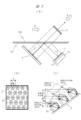
- FIG. 3 shows the main configuration of the spatially floating image information display system of the embodiment, and also shows an example (first method) relating to the formation of the spatially floating image 3 and the configuration of the retroreflective member 2 .
- this spatial floating image information display system projects image light of a specific polarized wave obliquely onto a transparent member 100, which is a transmissive plate such as glass.
- a video display device 10 that diverges to a narrow angle is provided.
- the image display device 10 includes a liquid crystal display panel 11 and a light source device 13 that generates specific polarized light having narrow-angle diffusion characteristics.
- the specific polarized image light emitted from the image display device 10 is reflected by the polarization separation member 101 provided on the transparent member 100 and having a film that selectively reflects the specific polarized image light.
- a sheet-shaped polarization separation member 101 is adhered to a transparent member 100 .
- a retroreflective member 2 is provided in the other diagonal direction with respect to the transparent member 100 .
- a ⁇ /4 plate 21 (in other words, a quarter-wave plate) is provided on the image light incident surface of the retroreflective member 2 .
- the image light passes through the ⁇ /4 plate 21 a total of two times, when it enters the retroreflecting member 2 and when it exits, thereby changing from a specific polarized wave (one polarized wave) to the other polarized wave. polarization conversion.
- the polarization separating member 101 that selectively reflects the image light of the specific polarized wave has the property of transmitting the polarized light of the other polarized wave after polarization conversion. Therefore, the image light of the other polarized wave after the polarization conversion passes through the polarization separation member 101 .
- the image light transmitted through the polarization separation member 101 forms a space floating image 3, which is a real image, outside the transparent member 100, as shown.
- the light that forms the floating image 3 is a set of light rays converging from the retroreflective member 2 to the optical image of the floating image 3, and these light rays travel straight even after passing through the optical image of the floating image 3. do. Therefore, the floating image 3 is an image having high directivity, unlike diffuse image light formed on a screen by a general projector or the like.
- the image 3 when the user views the image 3 from the direction of arrow A, the image 3 is viewed as a bright image.
- the floating image 3 cannot be visually recognized as an image at all.
- Such characteristics of the floating image 3 are very suitable for use in a system that displays images that require high security or highly confidential images that should be kept secret from a person facing the user.
- the polarization axes of the reflected image light may become uneven.
- part of the image light whose polarization axes are not aligned is reflected by the polarization separation member 101 described above and returns to the image display device 10 .
- a part of this image light is reflected again by the image display surface of the liquid crystal display panel 11 constituting the image display device 10, and generates a ghost image. This can be a factor causing deterioration in the image quality of the spatial floating image 3 .
- the image display surface of the image display device 10 is provided with the absorptive polarizing plate 12 .
- the absorptive polarizer 12 transmits the image light emitted from the image display device 10 and absorbs the reflected light returning from the polarization separation member 101. , can suppress re-reflection. Therefore, according to the present embodiment using the absorptive polarizing plate 12, it is possible to prevent or suppress deterioration in image quality due to the ghost image of the floating image 3.
- the polarization separation member 101 described above may be formed of, for example, a reflective polarizing plate or a metal multilayer film that reflects a specific polarized wave.
- FIG. 3B shows the surface shape of a typical retroreflective member 2, a retroreflective member manufactured by Nippon Carbide Industries Co., Ltd., used in this study.
- the retroreflective member 2 has regularly arranged hexagonal prismatic retroreflective portions (retroreflective elements) 2a on its surface.
- a light beam incident on the inside of the hexagonal prism is reflected by the wall surface and the bottom surface of the hexagonal prism, and is emitted as retroreflected light in a direction corresponding to the incident light.
- a floating image 3 is displayed.
- the resolution of this spatially floating image 3 largely depends on the resolution of the liquid crystal display panel 11 as well as the outer shape D and the pitch P of the retroreflective portion 2a of the retroreflective member 2 shown in FIG. 3(B).
- the resolution of the liquid crystal display panel 11 as well as the outer shape D and the pitch P of the retroreflective portion 2a of the retroreflective member 2 shown in FIG. 3(B).
- the diameter D of the retroreflective portion 2a is 240 ⁇ m and the pitch P is 240 ⁇ m. is 300 ⁇ m
- one pixel of the spatial floating image 3 corresponds to 300 ⁇ m. Therefore, the effective resolution of the spatially floating image 3 is reduced to about 1/3.
- the diameter D and the pitch P of the retroreflection portion 2a be close to one pixel of the liquid crystal display panel 11.
- the respective pitch ratios outside the integral multiple of one pixel.
- the retroreflective portion 2a is arranged so that no one side of the retroreflective portion 2a overlaps any one side of one pixel of the liquid crystal display panel 11.
- this method is a method of aligning the retroreflective portions 2a and shaping them on a film.
- the reverse shape of the shape to be shaped is formed on the surface of the roll, UV curable resin is applied on the base material for fixing, and it is passed between the rolls to shape the required shape, and the UV is irradiated and cured to obtain a retroreflective member 2 having a desired shape.
- FIG. 4 shows another example (referred to as a second method) of the formation of the spatially floating image 3 and the configuration of the retroreflective member in the spatially floating image information display system of this embodiment.
- FIG. 4A shows an overview of formation of the spatially floating image 3 using the retroreflective member 330 in the second method.
- Light from an object P (corresponding point P) in one space (in this example, the space below in the Z direction) with respect to the retroreflective member 330 enters the retroreflective member 330 and is retroreflected. , forms a spatial floating image 331 (corresponding point Q) in the other space (the upper space in the Z direction in this example).
- FIG. 4 shows a surface shape for explaining the operation principle of the retroreflective member manufactured by Asukanet Co., Ltd. used in this study as a representative retroreflective member 330 .
- the retroreflective member 330 has four-sided structures (in other words, tetrahedrons) 330A that are regularly arranged on the surface (the XY plane in the drawing). A plurality of structures 330A are arranged between sidewalls 330B.
- the four-sided structure 330A is, for example, a micromirror having a quadrangular prism shape extending in the Z direction. For example, light from an object P (also referred to as object light) enters the four-sided structure 330A.
- a light ray incident on the four-sided structure 330A is reflected by two surfaces (for example, the reflective surface RS1 and the reflective surface RS2) of the wall surfaces of the four-sided structure 330A.
- the reflected light rays (both the light rays emitted upward from the reflecting surface RS1 and the light rays emitted upward from the reflecting surface RS2) are shown as reflected light R0.
- the reflected light R0 is emitted as retroreflected light in a direction corresponding to the incident light, and forms and displays a floating image 331, which is a real image based on the object P, as shown in FIG. 4A.
- the retroreflective member 2 of the first method in FIG. Highly dependent on PT.
- the external shape (diameter) DS of the retroreflective portion is 120 ⁇ m and the pitch is 120 ⁇ m.
- PT is 150 ⁇ m
- one pixel of the spatial floating image 331 corresponds to 150 ⁇ m. Therefore, the effective resolution of the spatially floating image 331 is reduced to about 1/2.
- the diameter DS and the pitch PT of the retroreflective portion (structure 330A) be close to one pixel of the liquid crystal display panel.
- the retroreflective portion (structure 330A) be arranged so that no one side of the retroreflective portion (structure 330A) overlaps any one side of one pixel of the liquid crystal display panel.
- the light forming the floating image 331 is a set of light rays converging from the retroreflective member 330 to the optical image of the floating image 331, and these light rays travel straight after passing through the optical image of the floating image 331. do. Therefore, the spatially floating image 331 is an image having high directivity, unlike diffuse image light formed on a screen by a general projector or the like.
- the floating image 331 when viewed by the user from the direction of arrow A, the floating image 331 is viewed as a bright image.
- the floating image 331 cannot be visually recognized as an image at all.
- Such characteristics of the floating image 331 are similar to the image floating in the air using the retroreflective member 2 of the first method described above. It is very suitable for use in systems that display high-resolution images.
- the light from the object P is incident on the retroreflective member 330 from one side (lower side in the Z direction). , are reflected by the two reflecting surfaces (RS1 and RS2) provided on the four wall surfaces constituting the retroreflective member 330, and are reflected as reflected light R0 on the other side (upper side in the Z direction) at the position of the point Q , to form a spatial floating image 331 .
- the two reflecting surfaces (RS1, RS2) abnormal lights R1, R2 are generated as lights with reflection directions different from that of the reflected light R0.
- ghost images 332 and 333 as shown in FIG. 4A are generated by the extraordinary lights R1 and R2 generated by the two reflecting surfaces (RS1 and RS2). For this reason, the ghost images 332 and 333 can be factors that cause deterioration in the image quality of the spatially floating image 331 .
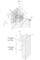
- the retroreflective member 2 of the first method produces a ghost image according to the number of reflecting surfaces.
- the retroreflective member 330 of the second method produces ghost images only in two specific directions depending on the incident angle of the object light. Therefore, the retroreflective member 330 of the second method is less affected by the ghost image, and enables high-quality spatial image display. Therefore, as the spatial floating image display device and the spatial floating image information display system described below, the description will focus on the case where the retroreflective member 330 of the second method is applied.
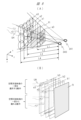
- FIG. 5 shows a specific method and configuration example for applying the image light control sheet to a spatially floating image display device.
- an image light control sheet 334 is provided on the exit surface of a liquid crystal display panel 335, which is an image display element.
- the exit surface of the liquid crystal display panel 335 is shown as a plane (XY plane) defined by the illustrated X-axis and Y-axis.
- the image light control sheet 334 has a transmitting portion and a light absorbing portion on the main surface (XY plane).
- moire may occur due to interference due to the pitch between the pixels of the liquid crystal display panel 335 and the transmission portions and light absorption portions of the image light control sheet 334 .
- the following two methods are effective.
- the ratio (B/A) of these is calculated from an integer multiple. selected value. Since one pixel of the liquid crystal display panel 335 is composed of sub-pixels of three colors of RGB arranged side by side and is generally square, it is impossible to suppress the occurrence of moire over the entire screen. For this reason, the inclination ⁇ 0 shown in the first method (1) is set within the range of 5 degrees to 25 degrees so that the moire generation position can be intentionally shifted to a location where the floating image is not displayed. should be optimized.
- the liquid crystal display panel and the image light control sheet 334 have been described.
- the same method and configuration can be applied to the moire that occurs in between. Since the retroreflective member 330 and the image light control sheet 334 are both linear structures, the image light control sheet 334 can be optimally tilted with attention paid to the X axis and the Y axis of the retroreflective member 330. . As a result, it is possible to reduce large moire patterns with a long wavelength and a low frequency that can be visually recognized.
- FIG. 6 shows a vertical sectional view of the image display device 10 having a configuration in which the image light control sheet 334 is arranged on the image light output surface 3351 of the liquid crystal display panel 335 .
- the image light control sheet 334 is configured by alternately arranging light transmitting portions 336 and light absorbing portions 337 on the main surface, and is adhesively fixed to the image light output surface 3351 of the liquid crystal display panel 335 by an adhesive layer 338 .
- the pitch B of the image light control sheet 334 is set to 340 ⁇ m when the distance d2 of the transmission portion 336 is 300 ⁇ m and the distance d1 of the light absorption portion 337 is 40 ⁇ m.
- the image light control sheet 334 controls sufficient transmission characteristics and diffusion characteristics of the image light from the image display device 10 that causes abnormal light, thereby reducing ghost images.
- the thickness of the image control sheet 334 is set to 2/3 or more of the pitch B, the ghost reduction effect is greatly improved.
- FIG. 6B shows a vertical sectional view of a configuration in which an image light control sheet 334 is arranged on the image light exit surface of the retroreflective member 330 (FIG. 4).
- the image light control sheet 334 is configured by alternately arranging light transmitting portions 336 and light absorbing portions 337, and has a predetermined inclination angle ⁇ 1 with respect to the retroreflecting member 330 in accordance with the emitting direction of the retroreflected light 3341. are slanted.
- the image light control sheet 334 absorbs the abnormal lights R1 and R2 ((B) in FIG. 4) generated by the above-described retroreflection, while normal reflected light is lost as retroreflected light 3341. can pass through without
- the retroreflective member 330 has an array of spaces 3301 corresponding to the retroreflective portions formed by the four-sided structures 330A (FIG. 4).
- a space 3301 corresponding to the retroreflective portion is separated by the surface of the side wall 330B.
- the space 3301 has, for example, a reflecting surface R1 and a reflecting surface R2.
- the light a1 incident on the retroreflective member 330 from, for example, the lower side is reflected by, for example, the reflective surface R1 of the space 3301, and the reflected light a2 is further reflected by, for example, the reflective surface R2, and reaches the upper side of the retroreflective member 330.
- the emitted light is incident on the image light control sheet 334 and emitted as retroreflected light 3341 .
- the pitch B of the image light control sheet 334 is such that the distance d2 of the transmitting portion 336 of the retroreflective member 330 is 400 ⁇ m and the distance d1 of the light absorbing portion 337 is 20 ⁇ m. Assume that the pitch B is 420 ⁇ m. In this case, the image light control sheet 334 controls sufficient transmission characteristics and diffusion characteristics of the image light from the image display device 10 that causes abnormal light to be generated in the retroreflective member 330, thereby reducing ghost images.
- the above-described image light control sheet 334 also prevents external light from entering the space-floating image display device, leading to improved reliability of the components.
- the image light control sheet 334 for example, viewing angle control film (VCF) manufactured by Shin-Etsu Polymer Co., Ltd. is suitable.
- VCF viewing angle control film
- the structure of the VCF is a sandwich structure in which transparent silicon and black silicon are alternately arranged, and a synthetic resin is arranged on the light input/output surface. Therefore, when this VCF is applied as the image light control sheet 334 of this embodiment, the above effects can be expected.
- a user (sometimes referred to as a user, a supervisor, an operator, etc.) is bidirectionally connected to the system via the spatially floating image 3 (FIG. 2, etc.) provided by the spatially floating image information display system 1 .
- the user uses a system application (for example, a kiosk terminal ticket sales function) or the like by viewing and operating the floating image 3 .
- a sensing technique is required for the user to operate the spatially floating image 3 in a pseudo manner and to sense the operation.
- the "sensing technology” here includes the aerial operation detection sensor 1351 and the aerial operation detection unit 1350 described with reference to FIG. technology.
- Aerial operation detection sensor 1351 and aerial operation detection unit 1350 may be referred to as a sensing system.
- FIG. 7 shows a principle diagram for explaining the first sensing technique.
- a spatially floating image FI by the spatially floating image information display system 1 is divided into a plurality of areas (in other words, regions).
- the plane of the spatially floating image FI is shown as the xy plane, and the front-rear direction with respect to the plane is shown as the z direction.
- the illustrated area A301 is one upper left area of the sensing plane a3.
- a first distance measuring device 340 incorporating a TOF (Time of Flight) system corresponding to each area of the spatially floating image FI is provided.
- a first rangefinder 340 is provided in place of the aerial operation detection sensor 1351 in FIG.
- a light emitting unit of the first distance measuring device 340 emits light from an LED (Light Emitting Diode) as a light source in synchronization with a system signal.
- An optical element for controlling the divergence angle is provided on the light emitting side of the LED, and a pair of highly sensitive avalanche diodes (APD) with picosecond time resolution are used as light receiving elements so as to correspond to 12 areas. , are aligned in 4 columns and 3 rows.
- the light source LED emits light
- the light is reflected by the object to be measured (here, the tip of the user's finger UH), and only the time until it returns to the light receiving part , the phase ( ⁇ t in FIG. 9 to be described later) shifts.
- the arithmetic unit of the sensing system shown in FIG. 9B receives the signal from the system and the signal generated by the avalanche diode, which is the light receiving part of the first rangefinder 340, and from these signals the phase Calculate the distance to the object by calculating the shift.
- a distance is calculated for each TOF system (TOF1 to TOF12) associated with each area.
- the sensing surfaces are arranged in order of proximity to the object.
- sensing plane a0 is shown as a measurement hierarchy on the side away from the spatial floating image FI.
- Distance L1 is the distance to sensing surface a0
- distance L2 is the distance to sensing surface a1
- distance L3 is the distance to sensing surface a2
- distance L4 is the distance to sensing surface a1.
- the sensing system recognizes which of the 12 areas the target object (finger UH) has passed through in each measurement layer (sensing planes a3 to a1), and performs each measurement. It can be recognized as a system by calculating the travel time between floors using the method described above.
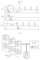
- FIG. 9 shows the light emission timing of the LED light source and the light reception timing of the light receiving element for each of the 12 measurement areas.
- SU1 to SU12 indicate light emission timing and light reception timing for each sensing unit associated with each area and TOF.
- the sensing system standardizes individual data by delaying the timing of LED light emission for each area.
- the sensing system uses these sensing signals (S1 to S3) to calculate and obtain the contact position with the spatially floating image FI from the moving direction of the finger UH and the time difference in crossing each sensing surface.
- a sensing plane a0 is set at a position farther away from the spatial floating image FI.
- the sensing system detects, as an end signal, that the finger UH has passed through the spatially floating image FI based on sensing on the sensing surface a0.
- a point of contact with the floating image FI is obtained as a three-dimensional coordinate.
- FIG. 7B shows an operation of selecting a portion of the floating image FI with the user's finger UH (especially the fingertip) and an operation of the user's finger UH leaving the portion of the floating image FI. show.
- the sensing system further senses the first sensing signal S3 sensed at the first sensing surface a1 based on the third sensing signal S3 sensed at the third sensing surface a3 and the second sensing signal S2 sensed at the second sensing surface a2.
- the sensing signal S1 is sequentially transmitted to the arithmetic unit of the sensing system for calculation processing. As a result, the system recognizes that the user's finger UH has left the specific coordinates of the floating image FI.
- FIG. 8 shows a principle diagram for explaining the second sensing technology.
- the second sensing technology is different from the first sensing technology shown in FIG. Realize accurate sensing.
- the first rangefinder 340 and the second rangefinder 341 may be installed side by side.
- a second sensing technique uses a second ranging device 341 (especially a CMOS sensor) as a second sensing system in combination with the first sensing system.
- the second rangefinder 341 senses the same range (sensing planes a1, a2, a3, a0) as the first rangefinder 340.
- the first distance measuring device 340 incorporates a TOF system corresponding to each of a plurality of areas divided into, for example, 12 areas in the spatial floating image FI (Fig. 8(B) 1st sensing system).
- the second distance measuring device 341 applies a two-dimensional image sensor, for example, a 1/4 inch CMOS sensor for sensing camera applications.
- the aspect ratio of this CMOS sensor is generally 3:4.
- the TOF system of the first distance measuring device 340 is also divided vertically into 3 parts and horizontally into 4 parts as described above, for a total of 12 areas, in accordance with the aspect ratio of the CMOS sensor.
- the resolution of the CMOS sensor is sufficient even with a resolution of about 1 million pixels, but unlike a normal camera system, there is no need to install an RGB color separation filter. For this reason, the CMOS sensor not only can realize miniaturization and high sensitivity with the same number of pixels, but also has high sensitivity to near-infrared light. Therefore, in the second sensing technology, the object (tip of the finger UH) to be ranged is illuminated by the light source light of the TOF system of the first rangefinder 340 at a timing determined for each area, so detection Greatly improves accuracy.
- FIG. 9B shows the system described above as a functional block diagram.
- FIG. 8B shows sensing surfaces a1, a2, and a3 by the first distance measuring device 340 and sensing surfaces b1, b2, and b3 by the second distance measuring device 341 provided corresponding thereto. indicates FIG. 8B shows an action of selecting a part of the spatially floating image FI and an action of leaving the part by the finger UH with respect to those sensing surfaces.
- the spatially floating image information display system using the second sensing technology when the user intentionally extends the finger UH toward the spatially floating image FI, the following occurs. Become. In this case, three-dimensional information is obtained by the second distance measuring device 341 in addition to the three-dimensional information by the first distance measuring device 340 described above.
- the planar resolution of the sensing surface b3 of the second rangefinder 341 corresponding to the sensing surface a3 of the first rangefinder 340, which is the farthest from the floating image FI, is highly accurate according to the resolution of the CMOS sensor used.
- the sensing surface b2 corresponds to the sensing surface a2
- the sensing surface b1 corresponds to the sensing surface a1. This makes it possible to realize a sensing system with greatly improved planar resolution.
- the moving direction of the object (the tip of the user's finger UH) is determined from the time difference across the sensing surfaces of the first rangefinder 340 and the second rangefinder 341, and the floating image FI. can be obtained by calculation.
- a sensing plane a0 is set that is farther away from the spatial floating image FI.
- the sensing system detects that the finger UH has passed through the floating image FI as an end signal, and from the position coordinates on the sensing plane a0 and the two sensing signals described above, the point of contact with the floating image FI is determined as follows. It can be calculated as three-dimensional coordinates with higher definition.
- the detection information by the second sensing technique is systematized with the position information by the first sensing technique by a synchronization signal supplied from the system.
- the A third sensing signal S3 sensed by the three sensing surfaces a3, a second sensing signal S2 sensed by the second sensing surface a2, and a first sensing signal S1 sensed by the first sensing surface a1 are sequentially sensed. It is communicated to the arithmetic units of the system. Then, the system recognizes that the user's finger UH has moved away from the specific coordinates of the spatially floating image FI through calculation processing in the arithmetic unit.
- the LED light source used in the TOF sensor of the first rangefinder 340 of the sensing system described above prevents the accuracy of the rangefinder from deteriorating due to external light such as sunlight, and the visible light range (380 nm to 780 nm) invisible to the naked eye. ), it is preferable to use near-infrared light, which has high light energy in a region exceeding .
- FIG. 10 shows a characteristic diagram of spectral irradiance of sunlight.
- the wavelength of the light source light of the LED of the TOF sensor it is preferable to use the light of wavelength ⁇ 1 of 920 nm, which has less energy in the spectral irradiance of the sunlight shown in FIG.
- the spatially floating image information display system can draw a line segment connecting these two points as an image on the plane of the spatially floating image based on the detection information of the contact position and the separation position.
- a spatially floating image information display system detects the point of contact between the spatially floating image and a user's fingertip, then moves the fingertip to another position within the plane, and the fingertip moves from the spatially floating image at the tip of the movement. Detects departure and departure points.
- This makes it possible to draw, for example, graphics such as line segments and curves, or characters such as alphabets and numbers on the surface of the spatially floating image.
- it is possible to input figures and characters on the surface of the floating image in the same way as drawing figures and characters on the surface of a liquid crystal display with a touch panel.
- the spatially floating image information display system uses sensing technology to sample the movement of the user's fingertip with respect to the spatially floating image at predetermined time intervals (for example, 100 milliseconds), and connects each sampling point. Draw a line in the space floating image.
- time intervals for example, 100 milliseconds
- characters and figures that can be drawn with a single stroke such as numbers 1, 2, and 3, and alphabets L and M, can be drawn as floating images.
- FIG. 12 shows an explanatory diagram of a technique for inputting/drawing an image such as a character or a figure with the user's fingers for the spatially floating image.
- FIG. 12 shows a schematic diagram of the spatially floating image FI displayed by the spatially floating image information display system 1 as viewed from the user's viewpoint.
- the spatially floating image FI is arranged diagonally with respect to the horizontal plane of the system housing 1201, and the user views the spatially floating image FI slightly obliquely downward.
- the spatially floating image FI includes the display of a rectangular frame 1202 (note that this is not a frame-like device). Assume that the frame 1202 is initially displayed in a predetermined color (for example, green) and only a predetermined background color is displayed within the frame 1202 .
- a predetermined color for example, green
- FIG. 12 shows how the user's fingertip UF draws the alphabet L as an example of a simple character on the surface of the floating image FI.
- the user informs the spatial floating image information display system 1 of his/her intention to draw the character in some way.
- a character input button 1203 is provided as a physical push button at an arbitrary location on the spatial floating image information display system 1, in this example, at the lower right position on the housing 1201.
- the system recognizes that the user intends to input characters or the like to the spatial floating image FI, and enters a mode for inputting/drawing to the spatial floating image FI (also referred to as a character input mode). Transition.
- a character input button may be displayed as a user interface in part of the spatially floating image FI provided by the spatially floating image information display system 1.
- the system similarly transitions to a mode for inputting/drawing the spatial floating image FI.
- the spatially floating image information display system 1 changes the entire screen of the spatially floating image FI to, for example, white display. Also, in the character input mode, the system changes the frame 1202 of the spatially floating image FI to a predetermined color, such as red. The system three-dimensionally senses the movement and contact position of the user's finger UF with respect to the surface of the spatially floating image FI as described above. Then, based on the sensing, the system draws the contact position corresponding to the movement of the finger UF on the surface of the spatially floating image FI in a predetermined color different from the background white, such as black or blue.
- a predetermined color such as red
- the trajectory of the movement of the finger UF is drawn as a line on the white background of the spatially floating image FI. Then, the user himself/herself can draw a desired character or figure while looking at the line drawn by himself/herself in the spatial floating image FI.
- the system is divided into two states: a state in which the finger UF is not in contact with the surface of the spatially floating image FI (in other words, a state in which the fingertip is in front of the surface) and a state in which the finger UF is in contact with the surface of the spatially floating image FI (in other words, The display is controlled so that the display state of the spatially floating image FI is different between the state in which the fingertip is inserted deep into the surface). This allows the user to more easily recognize whether or not his or her finger UF is touching the surface of the floating image FI.
- step S121 the user inserts the finger UF in the depth direction (in other words, maintains contact) at an arbitrary position on the spatially floating image FI.
- step S122 the user moves the finger UF downward on the spatial floating image FI while maintaining the contact state.
- a downward arrow indicates the moving direction of the finger UF (downward along the plane).
- the system draws a vertical line (first line) 1211 of the letter L as part of the spatial floating image FI.
- step S122 shows a state in which the finger UF has reached the lower terminal position of the first vertical line 1211 . Up to this point, the vertical first line 1211 has been drawn. The contact of the finger UF is maintained in this state.
- step S123 the user moves the finger UF rightward after the first line 1211 is drawn. The system draws a horizontal line (second line 1212) of the letter L upon detection of this movement. The position of the finger UF reaches the right end position of the second horizontal line 1212 .
- step S124 the user removes the finger UF located at the right end position of the second line 1212 from the surface of the spatial floating image FI toward the near side.
- the system detects this release of the finger UF and terminates the drawing of the second line 1212 .
- the user can draw the letter L on the spatial floating image FI with a single stroke.
- the character input button 1203 When the character input button 1203 is pressed by the user to enter the character input mode, not only does the entire screen (background surface) of the spatial floating image FI change to white, but also the portion of the frame 1202 of the spatial floating image FI changes to white. For example, it changes from green to red. This is preferable because the user can easily recognize that it is in the character input mode. Also, when the user wants to end the character input mode, the user can press the character input button 1203 again. In that case, the system exits the character input mode and returns to the original mode. In the above example, the entire screen of the spatially floating image FI is changed to white. However, the color is not limited to white, and may be a color other than white, such as black or another color.
- the frame 1202 of the spatially floating image FI may be changed to red, for example, by the user touching the spatially floating image FI (touching the finger UF) in the character input mode. .
- the user can recognize that his or her finger is in contact with the surface of the spatially floating image FI and is ready to draw characters.
- the frame 1202 of the floating image FI may also be colored in a color other than red, such as blue or another color.
- the entire screen of the spatial floating image FI is used as an area in which images such as graphics and characters can be input and drawn.
- the area in which an image can be input and drawn is not limited to this, and may be a predetermined part of the screen of the spatial floating image FI.
- the user can use the spatially floating image FI as a user interface such as an operation menu. ) makes it possible to input and draw arbitrary characters and figures. As a result, the application range of the spatially floating image and the spatially floating image display device can be further expanded, which is preferable.
- FIG. 13 shows the main configuration of a spatially floating image information display system 1 according to an embodiment.
- the spatially floating image information display system 1 of FIG. 13 is a system suitable for a user who is a supervisor to observe the spatially floating image 3 obliquely from above.
- the housing 350 of the spatial floating image information display system 1 is arranged on the horizontal plane (XY plane), and the spatial floating image 3 is arranged in the vertical direction (Z direction) in the front-rear direction (Y direction).
- the viewpoint E When viewing the surface of the spatially floating image 3 directly from the user's viewpoint E, the viewpoint E is aligned with the optical axis J2 with respect to the surface of the spatially floating image 3 in the Y direction, as shown in the figure. It is placed slightly obliquely upward. The user can preferably visually recognize the spatially floating image 3 with a line of sight slightly obliquely downward from the viewpoint E in the Y direction.
- the image display device 10 and the like are arranged in a predetermined positional relationship within the housing 350 .
- the upper surface (XY plane) of the housing 350 is an opening, and the retroreflective member 330 is arranged at a predetermined angle ⁇ 1.
- the optical axis J1 of the image display device 10 is directed obliquely upward at a predetermined angle ⁇ 1 with respect to the Y direction.
- the image display device 10 includes a liquid crystal display panel 11 as an image display element, and a light source device 13 that generates specific polarized light having narrow-angle diffusion characteristics.
- the liquid crystal display panel 11 can be applied from a small screen size of about 5 inches to a large screen size exceeding 80 inches, and is composed of a panel selected from them.
- Image light from the liquid crystal display panel 11 is emitted along the optical axis J1 toward a retroreflective member 330 (also referred to as a retroreflective portion or a retroreflective plate).
- a retroreflective member 330 also referred to as a retroreflective portion or a retroreflective plate.
- Light from a light source device 13 having a narrow divergence angle which will be described later, is incident on the liquid crystal display panel 11 .
- an image light flux ⁇ 1 with a narrow divergence angle is generated.
- the image light flux ⁇ 1 with a narrow divergence angle is made incident on the retroreflective member 330 from below in the Z direction along the optical axis J1. Due to the retroreflection by the retroreflection member 330, an image light beam ⁇ 2 with a narrow divergence angle is generated upward in the Z direction with respect to the retroreflection member 330 and in the direction of the optical axis J2, according to the principle explained with reference to FIG. be.
- a spatially floating image 3 (a spatially floating image 331 in FIG. 4) is obtained at a predetermined position outside the housing 350 by the image light flux ⁇ 2.
- the optical axis J2 is directed obliquely upward at a predetermined angle ⁇ 2 with respect to the Y direction.
- the spatially floating image 3 is formed at a symmetrical position of the image display device 10 with the retroreflective member 330 as the plane of symmetry.
- the surface of the image display device 10 and the surface of the floating image 3 are arranged at substantially symmetrical or symmetrical positions with respect to the obliquely arranged retroreflective member 330 .
- r2 indicates the center position corresponding to the optical axis J2
- r1 indicates the lower end position corresponding to the lower end ray of the image light beam ⁇ 2
- r3 corresponds to the upper end ray of the image light beam ⁇ 2. Indicates the top position.
- a control sheet 334 (more specifically, (A) in FIGS. 5 and 6) is provided. This controls the diffusion characteristics in unwanted directions.
- the image light from the liquid crystal display panel 11 can in principle have a higher reflectance at the reflecting member such as the retroreflecting member 330, so that the S polarized wave (the electric field component is perpendicular to the plane of incidence).
- electromagnetic waves S stands for senkrecht.
- the illustrated depolarization element 339 is provided as an element that optically converts part of the image light of the specific polarized wave into the other polarized wave to artificially convert it into natural light.
- a depolarizing element 339 is arranged on the output side of the image light control sheet 334 .
- COSMOSHINE SRF manufactured by Toyobo Co., Ltd.
- depolarizing adhesive manufactured by Nagase & Co., Ltd.
- COSMOSHINE SRF manufactured by Toyobo Co., Ltd.
- a depolarizing adhesive it is used by laminating a colorless transparent plate and an image display device via the depolarizing adhesive.
- an image light control sheet 334B (similar to the image light control sheet 334; details are shown in FIG. 6B) is provided on the image output surface of the retroreflective member 330 as well.
- the ghost images 332 and 333 (FIG. 4) generated on both sides of the normal image of the space floating image 3 due to unnecessary light are eliminated.
- the retroreflective member 330 is tilted at a predetermined angle ⁇ 1 with respect to the horizontal axis (Y direction), and the spatial floating image 3 is obliquely with respect to the horizontal axis (in particular, at an angle closer to the vertical plane than to the horizontal plane). diagonal).
- a first distance measuring device 340 is mounted at a predetermined position on the housing 350 . That is, this system implements the same sensing technology as in FIG. As a result, the user can access and interact with the floating image 3 in space.
- a first sensing system including the first distance measuring device 340 detects the state of operation by the user's finger or the like on the floating image 3 .
- a second sensing system including a second distance measuring device 341 may be added.
- the mounting position and viewing angle ⁇ 3 of the first distance measuring device 340 should be appropriately selected so that the size of the spatially floating image 3 can be sufficiently covered.
- the first distance measuring device 340 is located on the back side of the housing 350 in the Y direction (on the back side with respect to the position of the user and the floating image 3) and on the extension of the slope of the retroreflective member 330. , and is attached at a position shown in the drawing, which is a position a little apart so as not to block the image light flux of the image light.
- the viewing angle ⁇ 3 (the range from the upper end A to the lower end B) of the first distance measuring device 340 is the angle of view of the entire spatial floating image 3 and the user viewing it from the viewpoint E at the reference position (opposing position).
- the viewing angle is wide enough to cover areas including the face.
- the viewing angle ⁇ 3 includes the viewing angle ⁇ 2 that captures the entire space-floating image 3 .
- the viewing angle ⁇ 2 corresponds to the sensing planes a0, a1, a2, and a3 in FIG. 7, for example.
- the TOF sensor of the first rangefinder 340 uses a rangefinder system in which the sensing surface of the floating image 3 is divided into a plurality of areas, as shown in FIG. 7 (or FIG. 8). This increases the resolution for each sensing area. Furthermore, when using the second sensing technique using a CMOS sensor as shown in FIGS. 8 and 9B, the detection accuracy can be further improved.
- a light source that emits visible light having a narrow-angle directional characteristic is used as the light source device 13, and the first distance measuring device 340 is positioned to the outside of the narrow-angle image light flux on the housing 350 side. position.
- a second rangefinder 341 may also be arranged.
- FIG. 14 shows another embodiment of the spatial floating image information display system.
- the spatial image information display system 1 of FIG. 13 is a system suitable for the user to observe the spatial floating image 3 obliquely from above.
- the housing 350 of the spatial floating image information display system 1 is arranged on the horizontal plane (XY plane), and the spatial floating image 3 is arranged in the vertical direction (Z direction) in the front-rear direction (Y direction).
- the viewpoint E When viewing the surface of the spatially floating image 3 directly from the user's viewpoint E, the viewpoint E is aligned with the optical axis J2 with respect to the surface of the spatially floating image 3 in the Y direction, as shown in the figure. It is placed slightly obliquely upward. The user can preferably visually recognize the spatially floating image 3 with a line of sight slightly obliquely downward from the viewpoint E in the Y direction.
- the image display device 10, the mirror 360, etc. are arranged in a predetermined positional relationship.
- the opening of the housing 350 in this example, an opening having a plane (XZ plane) that stands roughly in the vertical direction, has a predetermined angle ⁇ 1 (a slightly downward inclined angle) with respect to the Z direction.
- a retroreflective member 330 is arranged.
- Mirror 360 is a plane mirror.
- image light from the image display device 10 is reflected by the mirror 360 and then enters the retroreflective member 330 .
- the housing 350 has a portion protruding upward in the Z direction, and the image display device 10 is arranged within that portion.
- the optical axis J1 of the image display device 10 is directed downward in the Z direction, backward in the Y direction, and obliquely downward at a predetermined angle ⁇ 1 with respect to the Z direction.
- the image display device 10 includes a liquid crystal display panel 11 as an image display element, and a light source device 13 that generates specific polarized light having narrow-angle diffusion characteristics.
- the liquid crystal display panel 11 can be applied from a small screen size of about 5 inches to a large screen size exceeding 80 inches, and is composed of a panel selected from them.
- the image light from the liquid crystal display panel 11 is turned back on the optical axis J1 by the mirror 360, which is an optical path turning mirror, and is emitted toward the retroreflecting portion 330 on the optical axis J1B after being turned back.
- Light from a light source device 13 having a narrow divergence angle, which will be described later, is incident on the liquid crystal display panel 11 .
- an image light flux ⁇ 1 with a narrow divergence angle is generated.
- the image light flux ⁇ 1 with a narrow divergence angle becomes image light flux ⁇ 1B after being reflected by the mirror 360 .
- the image light beam ⁇ 1B having a narrow divergence angle is made incident on the retroreflective member 330 from the right side in the Y direction shown in the figure along the optical axis J1B. Due to the retroreflection by the retroreflection member 330, an image light flux ⁇ 2 with a narrow divergence angle is generated in the left direction of the retroreflection member 330 in the Y direction and in the direction of the optical axis J2, according to the principle explained with reference to FIG. be.
- a spatially floating image 3 (a spatially floating image 331 in FIG. 4) is obtained at a predetermined position outside the opening of the housing 350 by the image light flux ⁇ 2.
- the optical axis J2 is directed obliquely upward at a predetermined angle ⁇ 2 with respect to the Y direction (an angle (90° ⁇ 2) with respect to the Z direction).
- the spatially floating image 3 is formed at a roughly symmetrical position with respect to the mirror 360 with the retroreflective member 330 as a plane of symmetry.
- the image display device 10 is arranged above the spatially floating image 3 in the Z direction.
- the retroreflective member 330 is positioned on the bottom surface of the housing 350 along the vertical axis ( Z direction) can be realized by arranging it at a predetermined angle ⁇ 1.
- the spatial floating image 3 that can be generated by external light entering the retroreflecting member 330 and entering the housing 350. image quality deterioration can be prevented.
- this embodiment In order to eliminate the ghost image (FIG. 4) that may occur in the spatially floating image 3 and obtain a higher quality spatially floating image 3, in the same way as in the second embodiment (FIG. 13), in this embodiment also: By providing an image light control sheet 334 ((A) in FIGS. 5 and 6) on the exit side of the liquid crystal display panel 11, diffusion characteristics in unnecessary directions may be controlled. Also, by providing an image light control sheet 334B ((B) in FIG. 6) on the image exit surface of the retroreflection member 330, ghost images generated on both sides of the normal image of the space floating image 3 due to unnecessary light are eliminated. You may
- the image light from the liquid crystal display panel 11 may be S-polarized as in FIG. 13, or P-polarized for polarized sunglasses.
- An element 339 may be provided.
- the retroreflective member 330 is tilted at a predetermined angle ⁇ 1 with respect to the vertical axis (Z direction), and the spatial floating image 3 is tilted with respect to the horizontal axis (in particular, at an angle closer to the vertical plane than the horizontal plane). diagonal).
- a first distance measuring device 340 ( FIG. 7 ) is mounted at a predetermined position on the housing 350 . That is, this system implements the same sensing technology as in FIG. As a result, the user can access and interact with the floating image 3 in space.
- a first sensing system including the first distance measuring device 340 detects the state of operation by the user's finger or the like on the floating image 3 .
- a second sensing system including a second distance measuring device 341 may be added.
- the mounting position and viewing angle ⁇ 3 of the first distance measuring device 340 should be appropriately selected so that the size of the floating image 3 can be sufficiently covered.
- the first distance measuring device 340 is located near the front of the retroreflective member 330 in the Y direction on the bottom surface of the housing 350 and is slightly away so as not to block the image light beam. position, shown.
- the viewing angle ⁇ 3 of the first distance measuring device 340 is, in this example, a sufficiently wide field of view so as to cover the entire space-floating image 3 and the area including the face of the user viewing it from the viewpoint E at the reference position. It is said to be a corner.
- the viewing angle ⁇ 3 includes the viewing angle that captures the entire space-floating image 3 .
- CMOS sensor such as (B) in FIGS. 8 and 9 may also be used.
- a light source that emits visible light having a narrow-angle directional characteristic is used as the light source device 13, and the first rangefinder 340 (further, the second rangefinder 341) is mounted on the housing. On the 350 side, it is arranged at an outer position with respect to the narrow-angle image light flux. As a result, it is possible to eliminate the adverse effect of the image light forming the spatially floating image 3 on the sensing accuracy.
- a capacitive touch panel 361 may be fixed with a supporting member 362 between the floating image 3 and the retroreflective member 330 as shown in the drawing.
- the supporting member 362 has a frame shape, for example, and supports the touch panel 361 inside.
- the support member 362 is fixed to the bottom surface of the housing 350, for example.
- the touch panel 361 is composed of a member that transmits image light for forming the spatially floating image 3 and light from the first distance measuring device 340 .
- This touch panel 361 detects the state of proximity of the user's fingers to the surface of the touch panel using a capacitive method. Alternatively, the touch panel 361 detects the contact state of the user's fingers on the surface of the touch panel. By using the third sensing technology including the touch panel 361 together with the first sensing technology or the like, detection accuracy can be further improved. Similarly, the size and mounting position of the capacitive touch panel 361 should be selected so that the floating image 3 can be sufficiently covered.
- a touch panel of this type for example, has ITO, which is a transparent electrode (Y-axis electrode) having a minute line-to-line distance, and a copper thin film, which is a transparent electrode (X-axis electrode) having a minute line-to-line distance, on a transparent glass substrate. It is manufactured by patterning by photolithographic etching on both sides of the . Therefore, when an object (for example, a fingertip) approaches this transparent glass substrate, the X-axis electrode and the Y-axis electrode detect changes in capacitance, and the relative coordinates of the object can be obtained. In addition, this method can achieve multi-point detection because the shorter the line-to-line distance of the transparent electrodes is, the higher the resolution can be obtained. Therefore, this method enables simultaneous input with a plurality of fingers.
- Embodiment 1 related to kiosk terminal>
- Embodiment 1 an example (referred to as Embodiment 1) in which the spatial floating image information display system 1 described above is applied to a so-called kiosk terminal will be described below.
- a kiosk terminal is an information terminal that allows an unspecified number of people to access necessary information and use various services through a man-machine interface such as a touch panel operation or a user interface.
- Kiosk terminals are installed in public facilities, transportation facilities, entertainment facilities such as amusement parks, and in recent years, inside so-called convenience stores. Kiosk terminals are also used for selling various types of tickets and administrative services (for example, issuance of resident cards).
- kiosk terminal is used to refer to an information terminal having a specific configuration. Instead of the term “kiosk terminal”, “information terminal”, “information display device”, “information processing terminal”, “ticket issuing terminal”, “document issuing terminal”, “administrative terminal”, “service terminal” and so on.
- the term “kiosk terminal” mainly used in the description of the embodiments is used as a representative example of these terms.
- FIG. 15 shows an example of the appearance of a general kiosk terminal based on conventional technology.
- This kiosk terminal 1400 includes a metal housing 1450 having a height of, for example, about 120 to 50 cm. and an input button 1420 are provided.
- the liquid crystal display screen 1410 is a part of the liquid crystal display device, and is a screen with a touch panel that displays various information and accepts a user's touch operation.
- the input button 1420 is a physical button for inputting a personal identification number or the like unique to the user, or a touch button in a screen configured with a touch panel.
- a part of the surface of the housing 1450 is provided with an outlet 1430 .
- the take-out port 1430 is a take-out port for taking out tickets, administrative documents, etc. issued as a result of an operation on the kiosk terminal 1400 .
- FIG. 16 shows an example of the external configuration of a kiosk terminal as the spatially floating image information display system of the first embodiment.
- FIG. 16 shows an outline of the kiosk terminal 1500 viewed obliquely from the right.
- the kiosk terminal 1500 in FIG. 16 differs from the kiosk terminal 1400 in FIG. 15 as follows.
- the kiosk terminal 1500 of FIG. 16 in addition to the liquid crystal display screen 1510 by the liquid crystal display device on the surface of the housing 1550 (especially the slope 1570), there is a space floating image display unit for displaying the space floating image 3 described above. 1520 is provided.
- the kiosk terminal 1500 has two screens, the liquid crystal display screen 1510 and the spatially floating image display section 1520, with two types of images. It is a configuration divided into two display units.
- the screen of the floating image display unit 1520 (also referred to as the first screen) is used as a basis.
- a concierge and an operation menu are displayed as a user interface using the space floating image 3 .
- the first screen of the spatial floating image display unit 1520 is based on an area of a predetermined size vertically and horizontally. In this example, the first screen has a slightly oblong size.
- the liquid crystal display screen 1510 (also referred to as the second screen) can display arbitrary images, and is used for purposes such as displaying advertisements, for example, similar to general kiosk terminals.
- the liquid crystal display screen 1510 is, for example, a liquid crystal touch panel screen equipped with a touch sensor.
- the second screen which is the liquid crystal display screen 1510, may be combined with the first screen of the spatial floating image display unit 1520 to be used as a user interface such as an operation menu.
- both the concierge and the operation menu may be displayed as one floating image 3 on the first screen of the floating image display unit 1520 in FIG.
- the displayed contents may be small and detailed, making it difficult to see. Therefore, in the embodiment of FIG. 16, display switching and the like are controlled so that one of the concierge and the operation menu is displayed as large as possible in the first screen.
- the positional relationship between the liquid crystal display screen 1510 and the floating image display section 1520 is not limited to the configuration example of FIG.
- the vertical arrangement of these may be reversed. That is, on the slope 1570, the floating image display unit 1520 may be arranged on the upper part and the liquid crystal display screen 1510 may be arranged on the lower part. In addition, they may be arranged side by side on the slope 1570 .
- FIG. 17 which will be described later, in a configuration in which a kiosk terminal 1500 includes a liquid crystal display screen 1510 and a spatial floating image display unit 1520, the liquid crystal display screen 1510 is arranged above and the spatial floating image display unit 1520 is arranged below. This configuration is more suitable for component arrangement in housing 1550 .
- the screens of these two display units are the liquid crystal display screen 1510 and the floating image display unit 1520, respectively.
- “This is a liquid crystal screen” or "This is a floating image” may be displayed on each screen. This improves usability for the user.
- notations such as “liquid crystal screen” and "space floating image” may be physically displayed in advance near the frame portion of each screen.
- a concierge 1521 (also referred to as a person image or a concierge image) is displayed as the spatial floating image 3 in the spatial floating image display section 1520 .
- an operation menu displayed on the floating image display unit 1520 can be operated.
- the concierge 1521 provides operation guidance (also referred to as operation guide, operation explanation, etc.) to the user by video and audio.
- the user can feel as if a real person (concierge) is present on the kiosk terminal 1500. Moreover, the concierge carefully explains to the user how to operate the kiosk terminal 1500 and the like. Therefore, even a user or the like who touches the kiosk terminal for the first time can easily operate the kiosk terminal 1500 and receive a desired service without being confused.
- the spatial floating image display unit 1520 in the embodiment of FIG. 16 may apply the configuration of the retroreflective member 2 or the like in FIG. 3 as a method for forming the spatial floating image 3,
- the configuration of the retroreflective member 330 or the like shown in FIGS. 13 and 14 may be applied.
- other methods that can display a spatially floating image in the air may be applied. Both are applicable.
- FIG. 17 a case in which the configuration of FIG. 14 is applied is shown.
- the detection method for detecting the user's operation on the spatially floating image 3 in the embodiment of FIG.
- a method based on the first or second sensing technique shown in FIGS. 7 and 8 may be applied.
- other methods that can detect mid-air operations on a spatially floating image may be applied. Either method is applicable.
- This embodiment shows a case (FIG. 17) in which the configurations of FIGS. 7 and 14 are applied.
- the kiosk terminal 1500 of FIG. 16 is provided with two cameras 1541 and 1542 at the left and right positions of the housing 1550 (especially the slope 1570). These cameras are stereo cameras corresponding to the imaging unit 1180 in FIG. Cameras 1541 and 1542 capture an area including the face and iris of a user (for example, the user who operates the floating image 3) who is near the front of the kiosk terminal 1500 (front side in the Y direction in the drawing). .
- the control unit 1110 (FIG. 2) of the kiosk terminal 1500 which is the spatial floating image information display system 1, performs processing for detecting that the user has approached the kiosk terminal 1500 based on the images captured by the cameras 1541 and 542, and identifies the user. - It is configured to perform identification processing or user authentication processing.
- a camera may be arranged inside the housing 1550, or a configuration may be adopted in which imaging information captured by a camera arranged outside is transmitted to the kiosk terminal 1500 by wire or wirelessly.
- the two cameras 1541 and 1542 on the left and right can be used for stereo imaging, and the user's face can be imaged as a stereoscopic image, and the distance and position to an object such as the face can be calculated. Therefore, in this system, compared to the case where a single camera captures the user's face as a two-dimensional image, the accuracy of user face authentication can be improved, and it is also suitable from the viewpoint of preventing unauthorized use.
- the kiosk terminal 1500 in FIG. 16 is provided with two speakers, particularly two super-directional speakers 1551 and 1552 (corresponding to the speaker/super-directional speaker 30 in FIG. 2) on the left and right sides of the housing 1550. It is By providing the super-directional speaker, it is possible to emit highly directional sound that can only be heard by the user who is trying to operate the kiosk terminal 1500 .
- the kiosk terminal 1500 may be equipped with a speaker that outputs normal audible sound, but in the following cases, a super-directive speaker is used so that other people other than the target user cannot hear it. It is preferable to adopt a configuration in which the audio speakers 1551 and 1552 are provided.
- the voice emitted from the kiosk terminal 1500 according to the user's operation for example, is the user's name, date of birth, input number information, etc.
- application of a super-directional speaker is suitable.
- the super-directional speakers 1551 and 1552 are installed so as to protrude outside the housing 1550, but they may be arranged inside the housing 1550 without being limited to this.
- the super-directional speakers 1551 and 1552 may output an audio signal indicating that a button or the like for the operation menu of the floating image 3 has been pressed so that only the user can hear it.
- FIG. 17 shows an explanatory diagram of the internal structure of the kiosk terminal 1500 of FIG.
- FIG. 17 shows a YZ cross section of the internal see-through when the housing 1550 of FIG. 16 is viewed from the right side.
- the upper portion of housing 1550 is shaped to have a slope 1570 .
- the image display device 10, the mirror 360, the retroreflection member 330, etc. which are the constituent elements of the spatially floating image information display system 1 explained in FIG. 14, are accommodated. Since this configuration is similar to that of FIG. 14, detailed description thereof will be omitted. Note that the touch panel 361 in FIG. 14 is not applied in FIG.
- a control device implementing the control unit 1110 of FIG. 2 a communication device implementing the communication unit 1132, and a power supply device may be accommodated.
- a human sensor 1560 may be provided on the lower portion (for example, the front surface) of the housing 1550 as shown. Human sensor 1560 detects that a person has approached kiosk terminal 1500 .
- the direction of image light emitted from the image display device 10 in the housing 1550 is changed by the mirror 360 and made incident on the retroreflective member 330 .
- the retroreflected light from the retroreflecting member 330 is emitted obliquely upward on the side opposite to the image display device 10 (the front side in the Y direction).
- a spatially floating image 3 is generated at the position of the spatially floating image display section 1520 .
- a slope 1570 of the housing 1550 has a predetermined angle ⁇ 1 with respect to the horizontal plane (Y direction).
- an opening (indicated by a dotted line) of the spatially floating image display section 1520 is provided at a position obliquely below the liquid crystal display screen 1510 above.
- a transparent member or the like may be provided in the opening.
- the image light from the retroreflection member 330 passes obliquely upward through the opening and forms the space-floating image 3 which is a real image at a predetermined position outside the slope 1570 .
- This spatially floating image 3 is formed so as to be tilted forward at a predetermined angle ⁇ 2 with respect to the slope 1570 .
- the spatially floating image 3 appears to protrude in front of the slope 1570 and float.
- the user can preferably view the spatially floating image 3 displayed on the spatially floating image display unit 1520 by looking diagonally downward from the obliquely upper viewpoint E, as in FIG. 14 .
- the optical path is turned back by the mirror 360 inside the housing 1550, so a longer optical path can be secured inside the housing 1550.
- a longer distance can be ensured for the spatially floating image 3 to project obliquely upward in front of the retroreflective member 330 .
- the thickness dimension of the housing 1550 in the depth direction (Y direction) can be suppressed.
- the first distance measuring device 340 (including the above-described TOF sensor, etc.) senses the range covering the entire spatially floating image 3 through the opening of the spatially floating image display unit 1520. .
- the lower end B of the sensing range of the first distance measuring device 340 is slanted above the horizontal plane (Y direction) to match the opening. (Y direction).
- the sensing range can be designed by changing the position of the opening of the housing 1550 and the arrangement position of the first rangefinder 340 .
- the sensing system including the first distance measuring device 340 detects whether the user has sufficiently approached the kiosk terminal 1500 (the slope 1570 of the housing 1550, or the spatially floating image 3, etc.), or is combined with the camera. may be used to assist in its detection. 17 with the first distance measuring device 340 and the second distance measuring device 341 as shown in FIG. Alternatively, the optical axis for distance measurement may be brought closer to the horizontal plane (Y direction).
- the kiosk terminal 1500 uses a sensing system including the first distance measuring device 340 to sense the operation of the user's fingers on the spatially floating image 3 of the spatially floating image display unit 1520 .
- the control unit 1110 of the kiosk terminal 1500 controls the display contents of the spatially floating image 3 on the spatially floating image display unit 1520 (user interfaces such as the concierge 1521 and an operation menu to be described later) according to the detection information including the sensing. do.
- the kiosk terminal which is the spatially floating image information display system of Embodiment 1, the user-friendliness and convenience are high, and the user of the kiosk terminal or the like can be provided with an interface and necessary information using a suitable spatially floating image.
- the system of the first embodiment even a user who has never operated a user interface such as an operation menu displayed as a floating image in space, a user who is unfamiliar with the operation, or an elderly user may be able to , provides operation guidance by a concierge as a friendly person image displayed as a space floating image. As a result, it is possible to avoid or reduce erroneous user input and erroneous operation with respect to the space-floating image interface, thereby enabling more reliable operation.
- FIG. 18 shows an external configuration example of another embodiment (referred to as Embodiment 2) related to the kiosk terminal.
- the kiosk terminal 1600 shown in FIG. 18 is different from the configuration in FIG. there is One screen by this spatial floating image display unit 1620 is larger in size than the screen of the spatial floating image display unit 1520 in FIG.
- the spatially floating image display unit 1620 has one vertically long screen on which one spatially floating image 3 is displayed.
- both the concierge and the operation menu are displayed side by side within the space floating image 3 of this one screen, and the concierge guides the operation of the operation menu.
- the space floating image 3 is displayed on the front side of the slope 1670.
- the spatial floating image 3 has a concierge 1621 projected on the top and an operation menu 1622 projected on the bottom.
- the operation menu 1622 includes, for example, operation buttons (indicated by circles and triangles).
- a concierge 1621 explains and guides how to operate the operation menu 1622 . 18, the user can easily operate the kiosk terminal 1600, especially the operation menu 1622, following the guidance of the concierge 1621, and receive the desired service, as in the case of FIG.
- FIG. 18 also includes cameras 1641 and 1642, super-directional speakers 1651 and 1652, and a human sensor 1660 in the housing 1650, which is the same as the configuration of FIG.
- FIG. 19 shows an explanatory diagram of an example of the internal structure of the kiosk terminal 1600 in FIG. 18, and shows a YZ cross section of the internal see-through when the kiosk terminal 1600 is viewed from the right side.
- This kiosk terminal 1600 accommodates the constituent elements of the spatial floating image information display system 1 of FIG. That is, the video display device 10, the retroreflective member 330, and the like are arranged in the upper part of the housing 1650. As shown in FIG.
- the video display device 10 is arranged roughly on a horizontal plane (more specifically, a state in which the back side is tilted slightly upward with respect to the Y direction) on the upper bottom surface of the housing 1650 .
- the optical axis J1 of the image display device 10 is generally directed vertically upward (in the Z direction).
- an opening (indicated by a dotted line) for the spatial floating image display section 1620 is provided on the slope 1670 of the upper portion of the housing 1650 .
- a retroreflective member 330 is arranged at a predetermined angle within the upper portion of the housing 1650 and near the opening thereof.
- the beveled surface 1670 has a predetermined angle ⁇ 1, and the retroreflective member 330 is arranged at a predetermined angle ⁇ 3 with respect to the beveled surface 1670.
- a spatially floating image 3 which is a real image, is generated at a predetermined position outside the opening in the spatially floating image display section 1620 of the slope 1670.
- This spatially floating image 3 is obliquely arranged at a predetermined angle ⁇ 2 with respect to the slope 1670.
- the user can preferably visually recognize the spatially floating image 3 from an obliquely upper viewpoint E and an obliquely downward line of sight.
- a first distance measuring device 340 (including a TOF sensor, etc.) is installed at a predetermined position in the upper portion of the housing 1650, in this example, at a position near the upper end of the retroreflective member 330. It is The optical axis of the first distance measuring device 340 faces the spatially floating image 3 and the viewing angle is set to cover the entire spatially floating image 3 .
- a sensing system including the first distance measuring device 340 mounted on the kiosk terminal 1600 senses an operation of the user's finger UH on the spatially floating image 3 of the spatially floating image display unit 1620 .
- both a concierge 1621 as the spatial floating image 3 and an operation menu 1622 as the spatial floating image 3 are displayed on one spatial floating image display unit 1620 at the same time.
- the display method of the spatial floating image on the kiosk terminal is not limited to this.
- the display of the concierge and the display of the operation menu may be switched within one screen of the floating image display unit 1620 .
- FIG. 20 shows an example of display of spatial floating image 3 on a kiosk terminal as an example (referred to as Embodiment 3).
- the kiosk terminal in FIG. 20 shows a configuration based on the kiosk terminal 1500 in FIG.
- the kiosk terminal of FIG. 20 is a kiosk terminal to which the spatially floating image 3 formed by the spatially floating image information display system 1 is applied as a user interface.
- 21 and 22 show the operation flow when the user operates the kiosk terminal of FIG.
- FIG. 21 shows the first operation flow involved when the kiosk terminal in FIG. 20 is activated.
- the first operation flow shows basic operations.
- the kiosk terminal is in a standby state (in other words, a sleep state).
- the kiosk terminal detects whether a user approaches the kiosk terminal. A user who intends to use the kiosk terminal approaches the kiosk terminal, or the user stands at a predetermined position near the kiosk terminal. When the user approaches this kiosk terminal, it is detected that the user has approached this kiosk terminal (in particular, the front of the slope 1570) based on the images taken by the cameras 1541 and 1542.
- FIG. instead of the camera, a motion sensor 1560 using infrared rays in FIG. If it is detected that the user has approached the kiosk terminal (YES), in step S102, the kiosk terminal transitions to the activated state. Then, in the activated state, the user can use the kiosk terminal.
- step S103 the kiosk terminal displays the concierge 1521 or the operation menu 1522 on the space-floating image display unit 1520, and guides the user on the operation method etc. while performing the operation (in other words, inputting) on the operation menu 1522. ), and performs predetermined processing (application or service processing) according to the detection of the operation.
- predetermined processing application or service processing
- FIG. 20A a concierge 1521 is displayed on the space-floating image display unit 1520, and the image and sound of the concierge 1521 greet the user and provide operational guidance.
- the display of the floating image display unit 1520 automatically transitions from the concierge 1521 to the operation menu 1522 as shown in FIG. 20B.
- the user operates the operation menu 1522 with fingers.
- the kiosk terminal detects an operation using sensing technology and performs processing according to the detected operation.
- the image of the concierge 1521 may be a moving image of an actual person taken in advance, a person image created by CG or the like, or an animation representing a person's appearance.
- it is not limited to people, and may be animals, fictional characters, or the like.
- step S104 it is detected whether the user has left the kiosk terminal.
- the kiosk terminal When the user leaves the kiosk terminal, it is detected that the user has left the kiosk terminal (especially the slope 1570 on the front) based on images taken by the cameras 1541 and 1542 .
- the motion sensor 1560 or the like in FIG. 16 may detect that the user has left the kiosk terminal. If it is detected that the user has left the kiosk terminal (Y), the kiosk terminal transitions to a standby state in step S105.
- FIG. 22 shows the second operation flow related to the activation of the kiosk terminal in Embodiment 3 of FIG.
- the second operation flow shows a more detailed embodiment than the first operation flow.
- the second operation flow shows an operation flow for performing user authentication and the like as operations after the kiosk terminal is activated.
- the kiosk terminal when the flow starts, the kiosk terminal is in a standby state.
- the user approaches the front of the kiosk terminal or stands at a predetermined position near the kiosk terminal.
- the kiosk terminal detects whether or not the user has approached this kiosk terminal (especially the front of the slope 1570) by stereo photography with two cameras or the like. If the user is detected (Y), in step S202, the kiosk terminal first displays the concierge 1521 on the floating image display unit 1520 as shown in FIG. , greeting the user, for example, "Welcome, thank you for using the service.”, and also displays a greeting message.
- the kiosk terminal authenticates the detected user.
- the kiosk terminal also displays a message indicating that authentication is in progress, such as "authenticating", as the floating image 3 in space.
- the kiosk terminal performs face authentication of an approaching person (that is, a detected user) based on the captured images (especially face images) of the two cameras 1551 and 1552, thereby identifying and specifying the user.
- face authentication may be based on an iris image of the user's eye.
- the authentication is based on the stereo image obtained by photographing the user's face or iris within a predetermined range in front of the kiosk terminal with two cameras. is the authorized user of this kiosk terminal registered in advance in this system.
- authentication based on the user's image is possible even by photographing with one camera, but by using stereo images from two cameras 1551 and 1552, it is possible to perform authentication based on the image from one camera. , it is possible to perform user authentication with higher accuracy and less fraudulent use. For example, it is possible to detect unauthorized authentication using a face image in which an image of the face taken only from the front is printed on paper.
- the following are also applicable as other methods of user authentication, not limited to the face authentication described above. It is also possible to apply a method of user authentication by having the kiosk terminal read information on personal identification such as a personal number card possessed by the user and information on a commuter pass. A method of performing user authentication by exchanging user information stored in a portable terminal or the like owned by the user through short-range wireless communication between the portable terminal and the kiosk terminal can also be applied.
- code information such as a QR code (registered trademark) containing personal information that can identify the user (for example, name, address, date of birth, kiosk terminal usage history, etc.) is displayed on a mobile terminal such as a smartphone owned by the user. Then, the code information is presented to the space-floating image display unit 1520 of the kiosk terminal (for example, held up to the cameras 1551 and 1552). A method of performing user authentication by reading the presented user information with the cameras 1551 and 1552 of the kiosk terminal can also be applied.
- QR code registered trademark
- step S204 the kiosk terminal confirms whether or not the above-mentioned user authentication has succeeded, and proceeds to step S206 in the case of success, and proceeds to step S205 in the case of failure.
- step S205 the kiosk prompts for another authentication method and returns to step S203 to attempt authentication with the other authentication method.
- the kiosk terminal may present a predetermined operation menu screen (an operation menu corresponding to an unspecified number of users) on the spatial floating image display unit 1520, or alternatively, the user may be authenticated. You may make it present the optimal menu screen (personal operation menu) for each user identified by .
- the display of the floating image display unit 1520 changes/transitions from the concierge 1521 to the operation menu 1522 as shown in (A) to (B) of FIG. 20 .
- the operation menu 1522 in (B) displays a message (text image) as an example of the contents, "Please select an item by touching it.” , "2. Ticket purchase", "3. Registered information", and "4. Another menu” are displayed.
- "1 Issuance of resident's card” is an item related to administrative procedures such as issuance of resident's card.
- "2 Ticket purchase” is an item related to the purchase and receipt of tickets for concerts, movies, trains, and the like.
- "3 Registered information” is an item related to confirmation and change of registered information related to the user.
- Another menu is an item for transitioning to another menu.
- the user presses, for example, the button for the item "2 Purchase ticket” depending on the purpose.
- the kiosk terminal causes the display to transition to the next operation menu according to the pressed button. A more detailed example is provided below.
- the spatial floating image information display system 1 of the kiosk terminal accesses the kiosk server on the communication network via the communication unit 1132 (FIG. 2) and notifies the user authentication result information.
- the kiosk terminal determines whether the user has used the kiosk terminal in the past by acquiring and referring to the user's attribute information from the user database in the kiosk server. do.
- the kiosk terminal may acquire and refer to the user's attribute information and the like based on the code information and the like from the user's portable terminal.
- the user attribute information includes, for example, the user's sex, age, past usage history of the kiosk terminal, and the like.
- the kiosk terminal may acquire user information including user attribute information from the user's portable terminal through wireless communication.
- the kiosk terminal receives other predetermined data related to the user and the operation menu from an external device such as a kiosk server, such as ticket reservation information and other information that the user has entered and registered in advance. You may acquire it together.
- the kiosk terminal may determine attributes such as age of the user based on the images of the cameras 1541 and 1542. FIG. The user attribute information acquired in step S206 is used in the determination of the next step S207.
- step S207 the kiosk terminal determines whether the user is a "first-time user” or an "elderly user” using the kiosk terminal based on the user attribute information obtained in step S206. to judge. If it is determined that the user satisfies such a predetermined condition (YES), the process proceeds to step S208, and if it is determined that the user does not satisfy the condition (NO), the process proceeds to step S209.
- the kiosk terminal omits the operation guidance by the concierge, or uses simplified operation guidance compared to the second processing flow.
- the kiosk terminal provides detailed operational guidance by the concierge.
- step S208 the kiosk terminal performs "operation guidance with audio by the concierge" on the spatial floating image display unit 1520.
- “concierge” means “guide”, and as shown in FIG. ) is displayed.
- the concierge 1521 provides the user with voice and gestures for the first time to operate a kiosk terminal using the floating image 3 as a user interface, or for an elderly user who is unfamiliar with the operation. Guidance on methods, etc. will be provided.
- the concierge 1521 explains and guides the user regarding the operation of the operation menu 1522 as shown in (B) where the user does not understand.
- step S208 first, an image of the concierge 1521 appears on the screen of the floating image display unit 1520, as shown in FIG. 20(A).
- the concierge 1521 outputs text video and voice such as "I will guide you on how to operate, so please operate the menu according to my explanation.”
- the audio is provided in a manner audible only to the user, for example, by super-directional speakers 1551, 1552 of FIG. 20(A).
- the concierge 1521 guides the user by sequentially telling the user how to use the kiosk terminal and the operation menu.
- step S208 the guidance by the concierge 1521 continues even after the screen of the floating image 3 is switched to the operation menu 1522.
- FIG. The kiosk terminal appropriately switches between display of the concierge 1521 and display of the operation menu 1522 on the floating image display unit 1520 .
- the user operates the operation menu 1522 on the screen of the space floating image display unit 1520 according to the operation guide of the concierge 1521 .
- step S210 the user performs a predetermined series of operations on the operation menu 1522 of the kiosk terminal, such as inputting a personal identification number for issuing a ticket.
- the kiosk terminal detects the operation, processes it, and issues a ticket.
- a user receives a ticket from the outlet 1530 . If the user's desired operation and the corresponding kiosk terminal operation, for example, ticket issuance are completed (Y), the process proceeds to step S212.
- step S212 the kiosk terminal again displays the operation menu 1622 (for example, the first menu screen, the next menu screen if there is a next menu, or the last menu screen, etc.) on the screen of the floating image display unit 1520. ).
- the kiosk terminal ends the display on the floating image display unit 1520 .
- the kiosk terminal may display the concierge 1521 on the screen at the end and output to the user that the display has ended (“Thank you for using the service”, etc.).
- step S209 the kiosk terminal performs display assuming that the user is familiar with the operation to some extent, not the first time.
- the kiosk terminal switches the screen display of the space floating image display unit 1520 to the operation menu 1522 as shown in FIG. 20B. Thereafter, the user performs desired operations such as selection of items according to the operation menu 1622 on the screen.
- step S211 similarly to step S210, if a series of predetermined operations and corresponding operations (for example, ticket issuance) are completed (Y), the process proceeds to step S212.
- step S212 is provided in consideration of the possibility that the user's operation may not go well even if the process proceeds to step S209.
- step S211 if the user does not complete the predetermined series of operations (N), the process proceeds to step S212.
- step S212 the kiosk terminal determines whether the user's operation in the operation menu 1522 is successful. In a specific example, the kiosk terminal determines whether the user's operation in the operation menu 1522 has stopped (in other words, there is no input) for a period of time longer than a predetermined period of time (for example, 30 seconds). The user may stop the operation when he/she does not understand the operation of the operation menu 1522 as the floating image 3 in space. The kiosk terminal uses a camera, sensing technology, etc. to detect the long-term inactivity. If it is determined that the operation has been stopped for a long time (Y), the process proceeds to step S206, and if not (N), the process proceeds to step S209.
- the kiosk terminal may determine whether the user is performing an incorrect operation on the surface of the floating image 3 (operation menu 1522). For example, it may be determined that the finger is about to touch at a position away from the item button or the like.
- the kiosk terminal displays the concierge 1521 on the spatial floating image display unit 1520 for the user, and guides the operation by the concierge 1521.
- the kiosk terminal may reproduce an operation guide according to predetermined contents as the operation guide by the concierge 1521, but more preferably, the operation of the operation menu 1522 where the user has stopped the operation in step S212 is performed. guide. For example, when the user's operation is stopped in the operation menu after the "2. Purchase ticket" button in (B) of FIG.
- the concierge 1521 guides the operator as to whether the operation should be performed.
- the kiosk terminal when the user approaches the kiosk terminal, displays the concierge 1521 as the floating image 3 and starts operation guidance by the concierge 1521 . Therefore, even a user who operates a kiosk terminal for the first time or a user such as an elderly person who is inexperienced in operation can receive operation guidance from the concierge 1521, sound from a super-directional speaker (operation guidance that other people cannot hear), etc. Accordingly, the predetermined operation can be reliably performed.
- the user is identified by authentication, and based on the user's age and system usage history, the concierge provides information to the user who is performing the operation for the first time, the user who is unfamiliar with the operation, and the elderly user.
- the concierge provides information to the user who is performing the operation for the first time, the user who is unfamiliar with the operation, and the elderly user.
- FIG. 25 shows a display example in the modified example.
- the kiosk terminal displays the image of the operation menu 1522 as large as possible within one screen of the spatially floating image 3 by the spatially floating image display unit 1520 .
- the kiosk terminal superimposes an image of the concierge 1521 on its operation menu 1522 in a relatively small size.
- the kiosk terminal guides the operation of the operation menu 1522 by the concierge 1521 .
- the concierge 1521 is a moving image including gestures, hand gestures, mouth and eye movements, etc., rather than a still image.
- the kiosk terminal may appropriately change the display presence or absence of the concierge 1521 and the display position within the screen of the operation menu 1522 .
- FIG. 23 shows, as another example (referred to as Embodiment 4), an example in which a kiosk terminal and a portable terminal held by a user perform cooperative operations.
- a kiosk terminal 1700 in FIG. 23 is a kiosk terminal to which the spatially floating image 3 formed by the spatially floating image information display system 1 is applied as a user interface.
- the kiosk terminal 1700 and a portable terminal 1740 such as a smart phone possessed by the user 1710 are linked.
- the kiosk terminal 1700 in FIG. 23 is based on the configuration of the kiosk terminal 1600 in FIG.
- the kiosk terminal 1700 authenticates the user 1710 and displays the concierge 1721 and the operation menu 1722 on the spatial floating image display unit 1720. do.
- the user operates the operation menu 1722 according to the guidance of the concierge 1721 or the like. For example, "2 Ticket purchase” is selected and operated from the operation menu 1522 as shown in FIG. 20(B).
- the kiosk terminal displays an operation menu 1722 transitioning from "2 Ticket purchase” on the screen of the floating image display unit 1720 in space.
- a user 1720 performs detailed operations for purchasing a ticket using an operation menu 1722 .
- a ticket is issued in a form printed on paper, for example, and the user 1710 receives the paper ticket.
- a method of obtaining a ticket it is possible not only to receive a ticket printed on paper, but also to receive it in the form of a so-called electronic ticket (or “e-ticket”).
- user 1710 receives the same information as the ticket printed on paper (that is, an electronic ticket) on portable terminal 1740 owned by user 1710 instead of the ticket printed on paper.
- a communication interface such as Bluetooth (registered trademark).
- the electronic ticket is directly transmitted from the kiosk terminal 1700 to the mobile terminal 1740 of the user.
- the kiosk terminal guides the communication operation by the concierge 1721 .
- the kiosk terminal 1700 displays the information content of the electronic ticket as a floating image 3 (for example, part of the operation menu 1722) on the screen of the floating image display unit 1720.
- Code information 1760 (in other words, code image) such as a barcode or QR code (registered trademark) is displayed.
- User 1710 reads the code information using his mobile terminal 1740 .
- the user 1710 performs an operation of reading the code information 1760 displayed in the operation menu 1722 with a reader function such as a camera of the portable terminal 1740 under the guidance of the concierge 1721 .
- Concierge 1721 guides the reading operation.
- the mobile terminal 1740 acquires an electronic ticket based on the read code information 1760 and holds it in a memory or the like inside the mobile terminal 1740 .
- the items and information that the user 1710 can receive from the kiosk terminal 1700 are not limited to paper tickets and electronic tickets, but may be, for example, coupons that can be used for shopping, point information, electronic books, and the like. Tickets and coupons printed on paper may be lost, but electronic tickets and coupons are held inside the mobile terminal 1740, so the possibility of loss can be reduced. In addition to reducing the possibility of loss, by holding electronic tickets and coupons inside the mobile terminal 1740, it is easier to use a mobile phone than tickets and coupons printed on paper. A form of use is possible, such as presenting a terminal or reading an electronic ticket held in a mobile terminal by a ticket issuer. This improves usability for the user.
- the kiosk terminal transmits information (for example, access history information, operation history information, etc.) related to the operation menu to the user's portable terminal by wireless communication in response to the user's operation on the operation menu of the floating image 3.
- information for example, access history information, operation history information, etc.
- FIG. 24 shows, as an example (embodiment 5), a detailed example of a function (FIG. 12) that allows the user to input and draw arbitrary characters and graphics on the floating image 3 described above. For example, when a user receives a paper-based ticket or an electronic ticket from a kiosk terminal through the series of procedures described in FIG. )I do.
- a kiosk terminal 2000 in FIG. 24 is an example based on the configuration of the kiosk terminals in FIGS.
- (A) shows a state in which a concierge 2021 is displayed as the spatially floating image 3 on the spatially floating image display unit 2020 .
- (B) shows a state in which a user interface for sign input is displayed as a floating image 3 in space.
- (C) shows a state in which the user's signature is input and drawn in the user interface.
- D shows a state in which a concierge 2021 is displayed as the spatial floating image 3 in response to the completion of sign input.
- the concierge 2021 outputs video and audio of a message to the user, for example, "Lastly, please sign to confirm that the customer has received the ticket.” This prompts the user to sign for the floating image 3 (in other words, sign for acceptance).
- the kiosk terminal erases the display of the concierge 2021, and as shown in FIG. user interface).
- the words "Please sign for ticket receipt” are displayed as characters drawn as the space floating image 3 on the signature screen 2022.
- a frame line (sign frame line area) 2023 indicating an area to be signed is displayed under the text.
- the frame line 2021 is displayed, for example, based on a predetermined background color (eg, black), and the frame lines on the four sides are displayed in a predetermined color (eg, green).
- a predetermined background color eg, black
- the frame lines on the four sides are displayed in a predetermined color (eg, green).
- the frame line 2021 is displayed in its predetermined color (for example, green).
- the user uses the tip of his/her finger UH or a predetermined conductive pen to sign his/her name, in this example, within the frame line 2023. Then, perform the operation to draw “Tom” in cursive.
- the kiosk terminal uses sensing technology to detect mid-air operations on the surface of the floating image 3, as in the case described above (FIG. 12), and adjusts the floating image according to the detected contact position of the fingertip. 3 (inside the frame line 2023), a line segment is drawn in real time.
- a line segment 2024 is a one-stroke line corresponding to the input/drawn signature (“Tom”). Line segment 2024 is displayed in a predetermined color.
- the kiosk terminal determines and detects that a predetermined time (for example, 5 seconds) has elapsed after the fingertip is released, it considers that the user's signature input has been completed. Then, the kiosk terminal causes a transition to a screen 2025 indicating the end of signature input, as shown in FIG. 24(D). On this screen 2025, for example, along with the appearance of the concierge 2021, a message such as "Thank you for your signature” is displayed and output as a voice. This completes the series of operations for the user to "sign" for acknowledging that the user has received the ticket.
- a predetermined time for example, 5 seconds
- the frame line 2023 is not limited to red, but may be of another predetermined color, such as blue. may be displayed in Also, the frame line 2023 may be blinked when there is contact. Furthermore, in the touched state, the background area within the frame line 2023 may be changed to white, and the color of the line segment written in the background area may be another predetermined color, such as black. Alternatively, the background area within the frame line 2023 may be black, and the line segments written in the background area may be white.
- the kiosk terminal controls the display in the sign frame area 2023 so that the user can easily recognize the line segments of characters and figures drawn according to the movement of the user's fingertip in the sign frame area 2023 .
- the kiosk terminal controls so as to change the mode of display in the sign frame area 2023 according to the state of fingertip contact with the sign frame area 2023 .
- Embodiment 5 a function (aerial sign function) is provided that allows the user to move his or her fingers to input any character or the like as a sign for the spatially floating image 3 . Also, with this function, the display of the frame line 2023 and the like changes depending on whether or not the fingertip is in contact with the surface of the floating image 3. It is easy to understand the state of whether or not you are doing it, and it is easy to enter your signature. In the above example, an example in which the input for the spatially floating image 3 is used for a sign has been shown, but it is not limited to this and can be used for other applications.
- FIG. 26 shows an example of a more specific configuration of the image display device 10 that constitutes the spatial floating image information display system 1.
- the light source device 13 of FIG. 26 has the same configuration as the light source device of FIG. 27 and the like, which will be described later.
- the light source device 13 is configured by housing an LED, a collimator, a polarization conversion element, a synthetic diffusion block, a light guide, etc. in a case made of plastic, for example.
- a liquid crystal display panel 11 is attached to the upper surface of the light source device 13 .
- an LED element 102A which is a semiconductor light source
- an LED substrate 102 on which a control circuit for the LED element is mounted are attached.
- a heat sink (not shown), which is a member for cooling the heat generated by the LED elements 102A and the control circuit, is attached to the outer surface of the LED substrate 102 .
- the liquid crystal display panel frame attached to the upper surface of the case includes the liquid crystal display panel 11 attached to the frame, and a flexible printed circuit (FPC) electrically connected to the liquid crystal display panel 11. ) etc. are attached. That is, the liquid crystal display panel 11, which is a liquid crystal display element, together with the LED element 102A, which is a solid-state light source, modulates the intensity of transmitted light based on a control signal from a control circuit that constitutes the electronic device, thereby displaying a display image. Generate.
- FPC flexible printed circuit
- FIG. 26 shows a cross section, so only one LED element and collimator are visible, but a plurality of LED elements are arranged on the LED substrate 102, and a plurality of collimators are arranged correspondingly. are arrayed.
- the collimators 15 are each made of translucent resin such as acrylic.
- the collimator 15 has a conical convex outer peripheral surface 156 obtained by rotating a parabolic section, and a convex portion (that is, a convex lens surface) 157 is formed in the central portion of the top portion (the side in contact with the LED substrate 102). It has a recess 153 .
- the central portion of the planar portion (the side opposite to the top portion) of the collimator 15 has an outwardly projecting convex lens surface (or an inwardly recessed concave lens surface) 154 .
- the paraboloid 156 forming the conical outer peripheral surface of the collimator 15 is set within an angle range capable of totally reflecting the light emitted from the LED element 102A in the peripheral direction. faces are formed.
- the LED elements 102A (LED elements 14a and 14b in FIG. 17A) are arranged at predetermined positions on the surface of the LED substrate 102, respectively.
- the LED substrate 102 is fixed to the collimator 15 so that the LED elements 102A on the surface thereof are located in the center of the concave portions 153, respectively.
- the collimator 15 As such a configuration, of the light emitted from the LED 102A by the collimator 15 described above, particularly the light emitted upward (to the right in the drawing) from the central portion forms the outer shape of the collimator 15.
- the light is condensed by the two convex lens surfaces 157 and 154 and becomes substantially parallel light.
- the light emitted in the peripheral direction from other portions is reflected by the paraboloid forming the conical outer peripheral surface of the collimator 15 and similarly condensed into substantially parallel light.
- the collimator 15 having a convex lens in the center and a paraboloid in the periphery, almost all the light generated by the LED element 102A can be extracted as parallel light. This makes it possible to improve the utilization efficiency of the generated light.
- a polarization conversion element 21 (in other words, a polarization conversion member) is provided on the light exit side of the collimator 15 .
- the polarization conversion element 21 is an element that converts the polarization characteristics of incident light.
- the polarization conversion element 21 includes a columnar (parallelogram prism) transparent member having a parallelogram cross section and a columnar (triangular prism) transparent member having a triangular cross section.
- An optical member is combined with the collimator 15 and arranged in an array parallel to a plane perpendicular to the optical axis of the parallel light from the collimator 15 .
- a polarizing beam splitter (PBS film) 211 and a reflective film 212 are alternately provided on the interface between the adjacent light-transmitting members arranged in an array.
- a ⁇ /2 phase plate 213 (in other words, a half-wave plate) is provided on the emission surface from which the light that has entered the polarization conversion element 21 and passed through the PBS film 211 is emitted.
- a rectangular composite diffusion block 16 is provided on the exit surface of the polarization conversion element 21 .
- the light emitted from the LED element 102A becomes parallel light by the action of the collimator 15, and after the polarization characteristics are converted by the polarization conversion element 21, it enters the synthesis diffusion block 16 and is diffused by the texture 161 on the output side. After that, it reaches the light guide 17 .
- the light guide 17 is a rod-shaped member with a substantially triangular cross section made of translucent resin such as acrylic.
- the light guide body 17 includes a light guide body light entrance portion 171 including an incident surface facing the exit surface of the combined diffusion block 16 via the first diffuser plate 18a. , a light guide light reflecting portion 172 including a reflective surface forming an inclined surface, and a light guide light emitting portion 173 including an emitting surface facing the liquid crystal display panel 11 via the second diffusion plate 18b. ing.
- the light guide body light reflecting portion 172 of the light guide body 17 has a large number of reflecting surfaces 172a and connecting surfaces 172b alternately formed in a sawtooth shape.
- the reflecting surface 172a (a line segment rising to the right in the drawing) forms an angle ⁇ n (n is a natural number and is 1 to 130 in this example) with respect to the horizontal plane.
- ⁇ n is set to 43 degrees or less (however, 0 degrees or more).
- the light guide entrance portion 171 is formed in a curved convex shape that is inclined toward the light source. According to this, the parallel light from the output surface of the synthetic diffusion block 16 is diffused through the first diffusion plate 18a and enters. As is clear from the drawing, this incident light is slightly bent and deflected upward by the light guide entrance portion 171, reaches the light guide light reflection portion 172, and is reflected there. This reflected light is emitted from the emission surface of the light guide emitting portion 173 on the upper side in the drawing, and reaches the liquid crystal display panel 11 provided for the emission surface.
- the image display device 10 it is possible to further improve the light utilization efficiency and the uniform lighting characteristics, and to manufacture the device including the modularized S-polarized light source device 13 at a small size and at a low cost.
- the polarization conversion element 21 is attached after the collimator 15 , but the invention is not limited to this.
- the light guide body light reflecting portion 172 a large number of reflecting surfaces 172a and connecting surfaces 172b are alternately formed in a sawtooth shape. Head. Further, the light guide body light emitting portion 173 is provided with a narrow-angle diffusion plate, and enters the light direction conversion panel 54 for adjusting the directional characteristics as a substantially parallel diffused light flux, and enters the liquid crystal display panel 11 from an oblique direction.
- the light direction changing panel 54 is provided between the light emitting surface of the light guide 17 and the liquid crystal display panel 11, but the light direction changing panel 54 may be provided on the light emitting surface of the liquid crystal display panel 11 in the same manner. effect is obtained.
- ⁇ Second Configuration Example of Image Display Device> Next, another example of the specific configuration of the video display device 10 will be described with reference to FIG. 28 .
- a plurality of LED elements constituting a light source are provided on the LED substrate 102, as in the above-described example (however, since this is a cross-sectional view, only one element is shown). there).
- These LED elements are attached to the collimator 15 at predetermined positions.
- a divergent luminous flux of light (a mixture of P-polarized light and S-polarized light) from the LED element is converted into a substantially parallel luminous flux by the collimator 15, and reflected toward the liquid crystal display panel 11 by the reflective surface of the reflective light guide 304. do.
- the reflected light enters the reflective polarizing plate 49 arranged between the liquid crystal display panel 11 and the reflective light guide 304 .
- a specific polarized wave (for example, P-polarized light) is transmitted through the reflective polarizing plate 49 and enters the liquid crystal display panel 11 .
- the other polarized wave (for example, S-polarized light) is reflected by the reflective polarizing plate 49 and directed to the reflective light guide 304 again.
- the reflective polarizing plate 49 is installed with an inclination so as not to be perpendicular to the principal ray of light from the reflecting surface of the reflective light guide 304 , and the principal ray of light reflected by the reflective polarizing plate 49 is is incident on the transmission surface of the reflective light guide 304 .
- the light incident on the transmissive surface of the reflective light guide 304 is transmitted through the back surface of the reflective light guide 304, transmitted through the ⁇ /4 plate 270 as a retardation plate, and reflected by the reflector 271.
- the light reflected by the reflecting plate 271 passes through the ⁇ /4 plate 270 again and passes through the transmitting surface of the reflective light guide 304 .
- the light transmitted through the transmission surface of the reflective light guide 304 enters the reflective polarizing plate 49 again.
- the light incident on the reflective polarizing plate 49 again passes through the ⁇ /4 plate 270 twice, and thus is polarization-converted into a polarized wave (for example, P-polarized light) that passes through the reflective polarizing plate 49. . Therefore, the light that has undergone polarization conversion passes through the reflective polarizing plate 49 and enters the liquid crystal display panel 11 .
- polarization design related to polarization conversion from the above description, it is also possible to reverse the polarization between the S-polarized light and the P-polarized light.
- the light from the LED element as the light source is aligned to a specific polarized wave (for example, P-polarized light), enters the liquid crystal display panel 11, is luminance-modulated in accordance with the video signal, and displays an image on the panel surface. indicate.
- a specific polarized wave for example, P-polarized light
- the collimators 15 in FIG. 28 are each made of translucent resin such as acrylic or glass. Like the collimator 15 in FIG. 27, the collimator 15 in FIG. 28 may have a conical convex outer peripheral surface obtained by rotating the parabolic cross section, and the top has a convex part in the center (that is, You may have the recessed part which formed the convex lens surface. In addition, the collimator 15 may have an outwardly protruding convex lens surface (or an inwardly concave concave lens surface) at the central portion of the “flat portion” of the collimator 15. The paraboloid is set within a range of angles in which the light emitted from the LED in the peripheral direction can be totally reflected inside, or a reflective surface is formed.
- the LED elements in FIG. 28 are arranged at predetermined positions on the surface of the LED substrate 102 respectively.
- the LEDs on the surface of the LED substrate 102 are arranged and fixed to the collimator 15 so as to be positioned at the center of the top of the conical projection (if the top has a recess, the recess).
- the collimator 15 According to such a configuration, of the light emitted from the LED elements by the collimator 15, particularly the light emitted from the central portion is collected by the convex lens surface forming the outer shape of the collimator 15 and becomes parallel light. Also, the light emitted in the peripheral direction from other portions is reflected by the paraboloid forming the conical outer peripheral surface of the collimator 15, and is similarly condensed into parallel light. In other words, with the collimator 15 having a convex lens in the center and a parabolic surface in the periphery, almost all of the light generated by the LED element can be extracted as parallel light. Light utilization efficiency can be improved.
- the configuration of the light source device 13 and the like described above can be applied as the light source device 13 of the image display device 10 constituting the spatial floating image information display system 1 shown in FIGS.
- the light converted into substantially parallel light by the collimator 15 shown in FIG. 28 is reflected by the reflective light guide 304 .
- the light of a specific polarized wave is transmitted through the reflective polarizing plate 49 by the action of the reflective polarizing plate 49, and the light of the other polarized wave reflected by the action of the reflective polarizing plate 49 is , passes through the light guide 304 again.
- This light is reflected by the reflector 271 located opposite to the liquid crystal display panel 11 with respect to the reflective light guide 304 .
- this light is polarization-converted by passing through the ⁇ /4 plate 270, which is a retardation plate, twice.
- the light reflected by the reflector 271 passes through the light guide 304 again and enters the reflective polarizing plate 49 provided on the opposite surface. Since this incident light has undergone polarization conversion, it passes through the reflective polarizing plate 49 and enters the liquid crystal display panel 11 with the polarization direction aligned. As a result, all the light from the light source can be used, so that the geometrical optics utilization efficiency of light is doubled.
- the degree of polarization (in other words, extinction ratio) of the reflective polarizing plate can be added to the extinction ratio of the entire system, the use of the light source device 13 of this embodiment significantly improves the contrast ratio of the entire display device. .
- the reflection diffusion angle of light on each reflecting surface can be adjusted.
- the surface roughness of the reflective surface of the reflective light guide 304 and the surface roughness of the reflector 271 may be adjusted for each design so that the uniformity of the light incident on the liquid crystal display panel 11 is more favorable.
- FIG. 29 is a diagram showing a case where the present invention is applied to, for example, a drink vending machine.
- the vending machine main body 2900 is provided with a spatial floating image display section 2920.
- the vending machine 2900 also includes a drink display section 2980 for displaying drinks sold by the vending machine 2900, a bill insertion section 2981 for inserting bills, and a coin insertion section for inserting coins. 2982, a change take-out port 2983 for taking out change, and a drink take-out port 2984 for taking out a drink purchased by the user.
- the vending machine main body 2900 is equipped with a camera or a motion sensor in the same way as the kiosk terminal, and when the user approaches, the space floating image display unit 2920 is activated.
- a concierge appears on the space-floating image display section 2920 and says, for example, "Welcome. Thank you for using our service.”
- the screen changes to number buttons. Please select the item number you want.”
- the space floating image display unit 2920 disappears from the concierge, and then the numeric buttons and the enter button are displayed.
- a cancel button and a return button may be displayed in addition to the numeric buttons and the enter button.
- the user selects a drink by operating the numeric buttons and decision button displayed on the floating image display unit 2920, and inserts a predetermined amount of money into the bill insertion unit 2981 or the coin insertion unit 2982.
- a drink is dispensed in a form that can be removed from the drink outlet 2984 .
- the floating image display unit 2920 disappears from the numeric buttons and the decision button, and the concierge appears again, and utters, for example, "Thank you very much. We look forward to seeing you again.” .
- the voice may be emitted from a normal speaker, or may be emitted from a super-directional speaker so that only the user can hear it.
- the user can purchase the desired drink.
- a floating image display unit is shown, but vending machines are also provided with both a liquid crystal display device and a floating image display unit, as in the example of a kiosk terminal.
- the spatially floating image display units may be provided at two or more locations instead of one location. If the floating image display units are provided at two locations, one of the floating image display units displays the concierge, and the other floating image display unit displays numbers. A button and an OK button may be displayed.
- a concierge you may display multiple characters with different ages and genders, different personal images and animations.
- Data for displaying a plurality of different human figures and animated characters of different ages and genders are stored in the non-volatile memory 1108 in FIG. One of them may be selected and displayed as a concierge on the spatial floating video display. In that case, it may be determined which person image or character to display according to the attributes of the user (age, etc.).
- a floating image display unit is provided, so that the user can select and purchase products without contact.
- it since it detects the user's approach to the vending machine and displays a floating image in space, it is possible to display a person image or character as a concierge in a display method not found in conventional vending machines.
- a person image or character as a concierge in a display method not found in conventional vending machines.
- the technology according to the embodiment by displaying high-resolution and high-brightness video information in a floating state in space, the user can operate without feeling anxious about contact infection of infectious diseases, for example. do. If the technology according to this embodiment is applied to a system used by an unspecified number of users, it will be possible to reduce the risk of contact infection of infectious diseases and provide a non-contact user interface that can be used without anxiety. According to the present invention that provides such technology, it contributes to "3 good health and well-being for all" of the Sustainable Development Goals (SDGs) advocated by the United Nations.
- SDGs Sustainable Development Goals
- the technique according to the embodiment by reducing the angle of divergence of emitted image light and aligning it to a specific polarized wave, only normal reflected light is efficiently reflected by the retroreflective member.
- the utilization efficiency of is high, and it is possible to obtain a bright and clear spatial floating image.
- the technology according to the embodiment it is possible to provide a highly usable non-contact user interface capable of significantly reducing power consumption.
- the Sustainable Development Goals SDGs: Sustainable Development Goals
- the technology according to the embodiment enables the formation of a spatially floating image by image light with high directivity (straightness).
- highly directional image light is displayed even when displaying images that require high security, such as so-called kiosk terminals, or highly confidential images that should be kept secret from a person facing the user. By doing so, it is possible to provide a non-contact user interface that is less likely to be peered into by someone other than the user.
- the present invention contributes to "11 Sustainable Development Goals" of the Sustainable Development Goals (SDGs) advocated by the United Nations.
Landscapes
- Engineering & Computer Science (AREA)
- Theoretical Computer Science (AREA)
- General Engineering & Computer Science (AREA)
- Physics & Mathematics (AREA)
- General Physics & Mathematics (AREA)
- Human Computer Interaction (AREA)
- Software Systems (AREA)
- Multimedia (AREA)
- Optics & Photonics (AREA)
- Signal Processing (AREA)
- Computer Hardware Design (AREA)
- Testing, Inspecting, Measuring Of Stereoscopic Televisions And Televisions (AREA)
- User Interface Of Digital Computer (AREA)
- Devices For Indicating Variable Information By Combining Individual Elements (AREA)
- Transforming Electric Information Into Light Information (AREA)
Abstract
Description
本開示は、例えば、大面積な映像発光源からの映像光による映像を、ショーウィンドのガラス等の、空間を仕切る透明部材を介して透過して、店舗空間の内部または外部に空間浮遊映像として表示可能な情報表示システムに関する。また、本開示は、かかる情報表示システムを複数用いて構成される大規模なデジタルサイネージシステムに関する。
図1の(A)は、実施例の空間浮遊映像情報表示システムの使用形態の一例を示し、空間浮遊映像情報表示システムの全体構成の説明図を示す。図1の(A)で、例えば、店舗等においては、ガラス等の透光性の部材(透明部材とも記載)であるショーウィンド(ウィンドガラスとも言う)105により、空間が仕切られている。本空間浮遊情報表示システムによれば、かかる透明部材を透過して、空間浮遊映像を、店舗空間の外部に対して一方向に表示が可能である。
図2は、空間浮遊映像情報表示システム1の機能ブロック図を示す。映像表示部1102は、映像信号に基づいて、映像表示部1102のパネルを透過する光を変調することで、映像を生成する。映像表示部1102は、例えば、透過型液晶表示パネルを用いてもよく、場合によっては、映像信号に基づいてパネルに反射する光を変調する反射型液晶表示パネルや、DMDパネル(DMD:Digital Micromirror Device、登録商標)などを用いて構成されてもよい。
図3は、実施例の空間浮遊映像情報表示システムにおける主要部構成を示し、また、空間浮遊映像3の形成、および再帰反射部材2の構成に関する一例(第1方式とする)を示す。
次に、図4は、本実施例の空間浮遊映像情報表示システムにおける空間浮遊映像3の形成、および再帰反射部材の構成に関する他の一例(第2方式とする)を示す。図4の(A)は、第2方式での再帰反射部材330を用いた空間浮遊映像3の形成の概要を示す。再帰反射部材330に対し、一方の空間(本例ではZ方向で下側の空間)内にある物体P(対応する点P)からの光は、再帰反射部材330に入射し、再帰反射されて、他方の空間(本例ではZ方向で上側の空間)内に、空間浮遊映像331(対応する点Q)を形成する。
ゴースト像を低減した高画質な空間浮遊映像を形成できる空間映像表示装置などを実現するためには、映像表示素子としての液晶表示パネルからの映像光の発散角を制御して、所望の方向に曲げるために、液晶表示パネルの出射面に映像光制御シートを設けるとよい。さらに、再帰反射部材330の光線出射面、または光線入射面、またはそれらの両面に、映光制御シートを設けて、ゴースト像を発生させる要因となる異常光R1,R2(図4の(B))を吸収させるとよい。
ユーザ(利用者、監視者、操作者などと記載する場合もある)は、空間浮遊映像情報表示システム1による空間浮遊映像3(図2等)を介して、システムと双方向で接続される。言い換えると、ユーザは、空間浮遊映像3を見て操作することで、システムのアプリケーション(例えばキオスク端末のチケット販売機能)等を利用する。そのために、ユーザが空間浮遊映像3を疑似的に操作してその操作をセンシングするためのセンシング技術が必要である。このセンシング技術の例について、以下に具体例を挙げて説明する。ここでいう「センシング技術」とは、図2を用いて説明した空中操作検出センサ1351および空中操作検出部1350を含み、特に、3次元空間におけるユーザの操作(言い換えると空中操作)を検出するための技術である。空中操作検出センサ1351および空中操作検出部1350を、センシングシステムと記載する場合がある。
次に、実施例の空間浮遊映像情報表示システムとして、ユーザが空間浮遊映像に文字や図形などの任意の像を入力できる技術について説明する。この技術を用いることで、ユーザが空間浮遊映像に対し例えばサイン(署名)の入力を行うことができる。
図13は、一実施例に係る空間浮遊映像情報表示システム1の主要部構成を示す。図13の空間浮遊映像情報表示システム1は、監視者であるユーザが空間浮遊映像3を斜め上方から観察するのに適したシステムである。図13中の座標系(X,Y,Z)では、空間浮遊映像情報表示システム1の筐体350が水平面(X-Y面)に配置されており、空間浮遊映像3は、鉛直方向(Z方向)に対し、前後方向(Y方向)でやや斜めに傾いて形成されている。ユーザの視点Eから、空間浮遊映像3の面を正対して好適に視認する場合、視点Eは、図示のように、空間浮遊映像3の面に対し、光軸J2に合わせて、Y方向でやや斜め上に配置される。ユーザは、視点EからY方向でやや斜め下の視線で空間浮遊映像3を好適に視認できる。
図14は、空間浮遊映像情報表示システムの他の実施例を示す。図13の空間映像情報表示システム1は、ユーザが空間浮遊映像3を斜め上方から観察するのに適したシステムである。図14中の座標系(X,Y,Z)では、空間浮遊映像情報表示システム1の筐体350が水平面(X-Y面)に配置されており、空間浮遊映像3は、鉛直方向(Z方向)に対し、前後方向(Y方向)でやや斜めに傾いて形成されている。ユーザの視点Eから、空間浮遊映像3の面を正対して好適に視認する場合、視点Eは、図示のように、空間浮遊映像3の面に対し、光軸J2に合わせて、Y方向でやや斜め上に配置される。ユーザは、視点EからY方向でやや斜め下の視線で空間浮遊映像3を好適に視認できる。
本発明の一実施の形態として、これまでに説明した空間浮遊映像情報表示システム1を、いわゆるキオスク端末に適用した実施例(実施の形態1とする)について以下に説明する。
図18は、キオスク端末に係わる他の実施例(実施の形態2とする)の外観構成例を示す。図18に示すキオスク端末1600は、図16の構成に対する違いとしては、液晶表示画面1510を備えず、筐体1650の斜面1670において、概略的に全面に、空間浮遊映像表示部1620が備えられている。この空間浮遊映像表示部1620による1つの画面は、図16での空間浮遊映像表示部1520の画面よりもサイズが大きい。図18の実施例では、空間浮遊映像表示部1620は、縦長のサイズの1つの画面を有し、1つの空間浮遊映像3が表示される。本例では、この1つの画面の空間浮遊映像3内に、コンシェルジュと操作メニューとの両方が並列で表示され、コンシェルジュが操作メニューの操作についてガイドする。
図20は、一実施例(実施の形態3とする)として、キオスク端末における空間浮遊映像3の表示の一例を示す。図20のキオスク端末は、図16のキオスク端末1500をベースとした場合の構成を示す。図20のキオスク端末は、空間浮遊映像情報表示システム1により形成される空間浮遊映像3をユーザインタフェースとして適用したキオスク端末である。図21,図22は、図20のキオスク端末をユーザが操作する場合の動作フローを示す。
図22のステップS206で、キオスク端末の空間浮遊映像情報表示システム1は、通信部1132(図2)を介して、通信網上のキオスクサーバにアクセスし、上記ユーザ認証の結果情報を通知する。また、キオスク端末は、当該ユーザが過去に当該キオスク端末を使用したことのあるユーザであるか否かを、キオスクサーバ内の利用者データベースから当該ユーザの属性情報などを取得・参照することで判断する。もしくは、キオスク端末は、上記ユーザの携帯端末からのコード情報等に基づいて、ユーザの属性情報などを取得・参照してもよい。ユーザの属性情報には、例えばユーザの性別、年齢、過去のキオスク端末の使用履歴などの情報を含む。
図23は、他の実施例(実施の形態4とする)として、キオスク端末と、ユーザが保持する携帯端末との連携動作を行う実施例を示す。図23のキオスク端末1700は、空間浮遊映像情報表示システム1により形成された空間浮遊映像3をユーザインタフェースとして適用したキオスク端末である。ユーザ1710がこのキオスク端末1700を操作する場合に、キオスク端末1700と、ユーザ1710が所持するスマートフォン等の携帯端末1740との連携を行う。図23のキオスク端末1700は、図18のキオスク端末1600の構成をベースとしている。
図24は、一実施例(実施の形態5とする)として、前述の空間浮遊映像3に対しユーザが任意の文字や図形を入力・描画できる機能(図12)に関する詳しい実施例を示す。例えば、図23等で説明した一連の手続きによって、ユーザがキオスク端末から紙ベースのチケットまたは電子チケットを受け取った場合に、ユーザが、チケットを受け取ったことをユーザが認めるための「サイン」(署名)を行う。
次に、図26以降を用いて、空間浮遊映像情報表示システム1の詳細構成例を説明する。図26は、空間浮遊映像情報表示システム1を構成する映像表示装置10についてのより具体的な構成の一例を示す。図26の光源装置13は、後述の図27等の光源装置と同様の構成を有する。この光源装置13は、例えばプラスチックなどのケース内に、LED、コリメータ、偏光変換素子、合成拡散ブロック、導光体等を収納して構成されている。その光源装置13の上面には、液晶表示パネル11が取り付けられている。また、光源装置13のケースの1つの側面には、半導体光源であるLED素子102Aや、LED素子の制御回路を実装したLED基板102が取り付けられている。それと共に、LED基板102の外側面には、LED素子102Aおよび制御回路で発生する熱を冷却するための部材であるヒートシンク(図示せず)が取り付けられる。
続いて、上記映像表示装置の第1構成例における、ケース内に収納されている光源装置等の光学系の構成例について、図26と共に、図27を参照しながら、詳細に説明する。図26で、光源を構成するLED102Aは、コリメータ15に対し、所定の位置に取り付けられている。なお、図26では、一断面を図示しているので、1つのLED素子やコリメータしか見えていないが、LED基板102には複数のLED素子が配列されており、それらに対応させて複数のコリメータが配列されている。コリメータ15は、各々、例えばアクリル等の透光性の樹脂により形成されている。コリメータ15は、放物断面を回転して得られる円錐凸形状の外周面156を有すると共に、頂部(LED基板102に接する側)における中央部に、凸部(即ち凸レンズ面)157が形成された凹部153を有する。
続いて、図28を用いて、映像表示装置10の具体的な構成の他の例を説明する。図28の映像表示装置10の光源装置は、前述の例と同様に、LED基板102に、光源を構成する複数のLED素子が設けられている(ただし断面図であるため1個のみ図示されている)。これらのLED素子はコリメータ15に対し所定の位置に取り付けられている。LED素子からの光(P偏光とS偏光が混在する光)の発散光束を、コリメータ15により略平行光束に変換し、反射型導光体304の反射面により、液晶表示パネル11に向けて反射する。反射光は、液晶表示パネル11と反射型導光体304との間に配置された反射型偏光板49に入射する。
ここで、図29を用いて、本発明の他の実施の形態として、空間浮遊映像情報表示システムを、自動販売機に適用した例について説明する。図29は、例えば、ドリンク類の自動販売機に本発明を適用した場合を示す図である。
Claims (29)
- 空中に空間浮遊映像を形成する空間浮遊映像情報表示システムであって、
少なくとも1個のオブジェクトの映像を表示する映像表示装置と、
前記映像表示装置からの映像光を再帰反射させることで空中に前記空間浮遊映像を形成するための再帰性反射部材と、
前記空間浮遊映像に対するユーザによる操作を検出するためのセンサを含むセンシングシステムと、
前記映像表示装置および前記再帰性反射部材を備えた筐体と、
検出された前記操作に基づいて所定の処理を実行する制御装置と、
を備え、
前記筐体に対し前記ユーザが近付いたことを検知した場合に、前記空間浮遊映像として前記オブジェクトの映像を表示する、
空間浮遊映像情報表示システム。 - 請求項1に記載の空間浮遊映像情報表示システムにおいて、
前記オブジェクトは、人物像としての形状を有する、
空間浮遊映像情報表示システム。 - 請求項2に記載の空間浮遊映像情報表示システムにおいて、
前記人物像は、前記ユーザに対し前記操作をガイドするコンシェルジュである、
空間浮遊映像情報表示システム。 - 請求項1に記載の空間浮遊映像情報表示システムにおいて、
前記筐体に対し前記ユーザが近付いたことを検知した場合に、前記空間浮遊映像として、最初に、前記オブジェクトとしての人物像を表示し、次に、操作メニューを表示する、
空間浮遊映像情報表示システム。 - 請求項1に記載の空間浮遊映像情報表示システムにおいて、
前記筐体に対し前記ユーザが近付いたことを検知した場合に、前記空間浮遊映像として、前記オブジェクトとしての人物像と操作メニューとの両方を表示する、
空間浮遊映像情報表示システム。 - 請求項1に記載の空間浮遊映像情報表示システムにおいて、
前記ユーザを撮像する撮像装置を備え、
前記撮像装置により取得した前記ユーザが写った画像に基づいて、前記ユーザが近付いたことを検知する、
空間浮遊映像情報表示システム。 - 請求項4に記載の空間浮遊映像情報表示システムにおいて、
前記制御装置は、前記ユーザの認証を行い、前記認証の結果に基づいて、前記オブジェクトとして前記人物像の表示から前記操作メニューの表示へ遷移させる、
空間浮遊映像情報表示システム。 - 請求項1に記載の空間浮遊映像情報表示システムにおいて、
前記ユーザを撮像する撮像装置を備え、
前記撮像装置により取得した前記ユーザが写った画像に基づいて、前記ユーザの認証を行う、
空間浮遊映像情報表示システム。 - 請求項1に記載の空間浮遊映像情報表示システムにおいて、
前記空間浮遊映像として、少なくとも2つ以上の選択肢を含んだ操作メニューを表示する、
空間浮遊映像情報表示システム。 - 請求項3に記載の空間浮遊映像情報表示システムにおいて、
前記空間浮遊映像として、前記コンシェルジュと、少なくとも2つ以上の選択肢を含んだ操作メニューとを表示し、
前記コンシェルジュの映像および音声により、前記操作メニューに対する操作をガイドする、
空間浮遊映像情報表示システム。 - 請求項1に記載の空間浮遊映像情報表示システムにおいて、
前記ユーザにのみ聴取可能に音声信号を出力する超指向性スピーカを備える、
空間浮遊映像情報表示システム。 - 請求項3に記載の空間浮遊映像情報表示システムにおいて、
前記制御装置は、前記ユーザの属性情報を取得し、前記属性情報に基づいて、前記ユーザが前記空間浮遊映像情報表示システムを初めて使用するユーザであるか、所定の年齢以上のユーザであるか、の少なくともいずれかを含む条件を判定し、
前記条件を満たすユーザに対し、前記空間浮遊映像として前記コンシェルジュによるガイドを行う、
空間浮遊映像情報表示システム。 - 請求項10に記載の空間浮遊映像情報表示システムにおいて、
前記制御装置は、検出された前記操作に基づいて、書類を発行する処理を実行し、
前記筐体の一部に、前記書類の取り出し口を備える、
空間浮遊映像情報表示システム。 - 請求項13に記載の空間浮遊映像情報表示システムにおいて、
前記空間浮遊映像情報表示システムは、前記書類としてチケットまたは行政証書を発行する機能を有するキオスク端末である、
空間浮遊映像情報表示システム。 - 請求項1に記載の空間浮遊映像情報表示システムにおいて、
前記ユーザの所持する携帯端末との間で無線通信を行う通信部を備える、
空間浮遊映像情報表示システム。 - 請求項15に記載の空間浮遊映像情報表示システムにおいて、
前記無線通信に基づいて、前記携帯端末から送信された前記ユーザの情報を受信する、
空間浮遊映像情報表示システム。 - 請求項15に記載の空間浮遊映像情報表示システムにおいて、
前記制御装置は、検出された前記操作に基づいて、書類を発行する処理を実行し、
前記無線通信に基づいて、前記書類の情報を前記携帯端末に送信する、
空間浮遊映像情報表示システム。 - 請求項1記載の空間浮遊映像情報表示システムにおいて、
前記空間浮遊映像として、前記ユーザの携帯端末に読み取らせるためのコード情報を表示する、
空間浮遊映像情報表示システム。 - 請求項1記載の空間浮遊映像情報表示システムにおいて、
前記ユーザを撮像する撮像装置を備え、
前記撮像装置により、前記ユーザの携帯端末に表示されたコード情報を読み取る、
空間浮遊映像情報表示システム。 - 空中に空間浮遊映像を形成する空間浮遊映像情報表示システムであって、
少なくとも1個のオブジェクトの映像を表示する映像表示装置と、
前記映像表示装置からの映像光を再帰反射させることで空中に前記空間浮遊映像を形成するための再帰性反射部材と、
前記空間浮遊映像に対するユーザによる操作を検出するためのセンサを含むセンシングシステムと、
前記映像表示装置および前記再帰性反射部材を備えた筐体と、
検出された前記操作に基づいて所定の処理を実行する制御装置と、
を備え、
前記操作として、前記空間浮遊映像の面に対する前記ユーザの手指または所持物による接触の状態を、前記センシングシステムを用いて検出し、
前記空間浮遊映像の面において前記接触がされた位置に線を前記空間浮遊映像として描画する、
空間浮遊映像情報表示システム。 - 請求項20に記載の空間浮遊映像情報表示システムにおいて、
前記制御装置は、前記空間浮遊映像の面において文字や図形として描画された前記線を、前記ユーザによる入力情報として取得する、
空間浮遊映像情報表示システム。 - 請求項21に記載の空間浮遊映像情報表示システムにおいて、
前記制御装置は、前記空間浮遊映像の面において文字や図形として描画された前記線を、前記ユーザによるサインとして取得する、
空間浮遊映像情報表示システム。 - 請求項20に記載の空間浮遊映像情報表示システムにおいて、
前記空間浮遊映像の面において描画される前記線は、前記ユーザの氏名または属性に関する情報である、
空間浮遊映像情報表示システム。 - 請求項20に記載の空間浮遊映像情報表示システムにおいて、
前記空間浮遊映像の全体または一部の領域に、枠を表示し、
前記制御装置は、前記空間浮遊映像の面における前記一部の領域に対する前記ユーザの手指または所持物による接触の有無に応じて、前記枠の色を変えるように、表示を制御する、
空間浮遊映像情報表示システム。 - 請求項20に記載の空間浮遊映像情報表示システムにおいて、
前記空間浮遊映像の全体または一部の領域に、枠を表示し、
前記制御装置は、前記空間浮遊映像の面における前記枠の内側の領域に対する前記ユーザの手指または所持物による接触の有無に応じて、前記枠の内側の領域の背景色を変えるように、表示を制御する、
空間浮遊映像情報表示システム。 - 請求項20に記載の空間浮遊映像情報表示システムにおいて、
前記空間浮遊映像の全体または一部の領域に、枠を表示し、
前記制御装置は、前記空間浮遊映像に対し前記線を描画するモードと、前記空間浮遊映像に対し前記線を描画しないモードとの切り替えを制御し、前記線を描画するモードと前記線を描画しないモードとで、前記枠の色を変えるように、表示を制御する、
空間浮遊映像情報表示システム。 - 請求項20に記載の空間浮遊映像情報表示システムにおいて、
前記空間浮遊映像の全体または一部の領域に、枠を表示し、
前記制御装置は、前記空間浮遊映像の面に対する前記ユーザの手指または所持物による接触の有無に応じて、前記枠を点滅させるように、表示を制御する、
空間浮遊映像情報表示システム。 - 請求項20に記載の空間浮遊映像情報表示システムにおいて、
前記筐体の所定の箇所に、前記空間浮遊映像の面に対する前記操作の検出および前記線の描画を行うモードに移行させるための物理的なボタンを備える、
空間浮遊映像情報表示システム。 - 請求項20に記載の空間浮遊映像情報表示システムにおいて、
前記空間浮遊映像の面に対する前記操作の検出および前記線の描画を行うモードに移行させるためのボタンを、前記空間浮遊映像の一部として表示する、
空間浮遊映像情報表示システム。
Priority Applications (2)
| Application Number | Priority Date | Filing Date | Title |
|---|---|---|---|
| US18/718,560 US20250053241A1 (en) | 2021-12-13 | 2022-10-17 | Air floating video information display system |
| CN202280081334.9A CN118355356A (zh) | 2021-12-13 | 2022-10-17 | 空间悬浮影像信息显示系统 |
Applications Claiming Priority (2)
| Application Number | Priority Date | Filing Date | Title |
|---|---|---|---|
| JP2021201690A JP7792785B2 (ja) | 2021-12-13 | 2021-12-13 | 空間浮遊映像情報表示システム |
| JP2021-201690 | 2021-12-13 |
Publications (1)
| Publication Number | Publication Date |
|---|---|
| WO2023112463A1 true WO2023112463A1 (ja) | 2023-06-22 |
Family
ID=86774408
Family Applications (1)
| Application Number | Title | Priority Date | Filing Date |
|---|---|---|---|
| PCT/JP2022/038557 Ceased WO2023112463A1 (ja) | 2021-12-13 | 2022-10-17 | 空間浮遊映像情報表示システム |
Country Status (4)
| Country | Link |
|---|---|
| US (1) | US20250053241A1 (ja) |
| JP (2) | JP7792785B2 (ja) |
| CN (1) | CN118355356A (ja) |
| WO (1) | WO2023112463A1 (ja) |
Cited By (1)
| Publication number | Priority date | Publication date | Assignee | Title |
|---|---|---|---|---|
| WO2025041524A1 (ja) * | 2023-08-23 | 2025-02-27 | マクセル株式会社 | 空中浮遊映像表示装置 |
Families Citing this family (4)
| Publication number | Priority date | Publication date | Assignee | Title |
|---|---|---|---|---|
| WO2024257499A1 (ja) * | 2023-06-13 | 2024-12-19 | マクセル株式会社 | 空中浮遊映像表示装置、携帯端末、および表示方法 |
| JP2025070162A (ja) * | 2023-10-19 | 2025-05-02 | 東芝テック株式会社 | 商品登録端末、商品登録方法及びプログラム |
| TW202526447A (zh) * | 2023-12-18 | 2025-07-01 | 幻景啟動股份有限公司 | 整合平面顯示器與浮空影像顯示器的系統與運作方法 |
| JP2025102349A (ja) * | 2023-12-26 | 2025-07-08 | マクセル株式会社 | 空中浮遊映像表示装置、商品自動販売機、および表示装置 |
Citations (5)
| Publication number | Priority date | Publication date | Assignee | Title |
|---|---|---|---|---|
| JP2009009280A (ja) * | 2007-06-27 | 2009-01-15 | Toyota Infotechnology Center Co Ltd | 3次元署名認証システム |
| JP2009259127A (ja) * | 2008-04-18 | 2009-11-05 | Konica Minolta Business Technologies Inc | 表示操作部を備えた装置 |
| CN102023784A (zh) * | 2009-09-16 | 2011-04-20 | 创新科技有限公司 | 非接触式输入字符的方法和设备 |
| JP2013157845A (ja) * | 2012-01-31 | 2013-08-15 | Seiko Epson Corp | 電子鏡およびそのプログラム |
| JP2014182459A (ja) * | 2013-03-18 | 2014-09-29 | Fujitsu Ltd | 情報処理装置及びプログラム |
Family Cites Families (14)
| Publication number | Priority date | Publication date | Assignee | Title |
|---|---|---|---|---|
| JPS63291111A (ja) * | 1987-05-25 | 1988-11-29 | Fujitsu Ltd | 操作ガイダンス出力制御方法 |
| JPH11259199A (ja) * | 1998-03-13 | 1999-09-24 | Toshiba Corp | 端末装置、入力画面表示方法及び入力画面表示プログラムを記録した記録媒体 |
| JP2006085359A (ja) | 2004-09-15 | 2006-03-30 | Fuji Xerox Co Ltd | ユーザインタフェース装置 |
| US8904312B2 (en) * | 2006-11-09 | 2014-12-02 | Navisense | Method and device for touchless signing and recognition |
| JP2008122196A (ja) | 2006-11-10 | 2008-05-29 | Denso Corp | カーナビゲーション装置 |
| US20130159027A1 (en) * | 2011-12-19 | 2013-06-20 | Amir Naor | Methods and systems for travel booking and management |
| US9854014B2 (en) * | 2013-03-14 | 2017-12-26 | Google Inc. | Motion data sharing |
| JP5809202B2 (ja) * | 2013-06-21 | 2015-11-10 | シャープ株式会社 | 画面操作可能な画像表示装置及びその操作方法 |
| KR102510944B1 (ko) * | 2016-05-16 | 2023-03-16 | 삼성전자주식회사 | 입체 영상 장치 및 그를 포함하는 전자 장치 |
| JP7347414B2 (ja) * | 2018-05-15 | 2023-09-20 | ソニーグループ株式会社 | 情報処理システム、情報処理方法、および記録媒体 |
| US10469674B1 (en) * | 2018-05-31 | 2019-11-05 | Kyocera Document Solutions Inc. | Image forming apparatus, image forming system, and communication processing method with drawing mode drawing in self-apparatus at time of remote maintenance connection |
| US10783428B2 (en) * | 2018-07-05 | 2020-09-22 | Accenture Global Solutions Limited | Holographic virtual assistant |
| CN111338494B (zh) * | 2018-12-19 | 2022-03-25 | 华为技术有限公司 | 一种触控显示屏操作方法和用户设备 |
| US11613395B2 (en) * | 2020-12-10 | 2023-03-28 | Rockwell Collins, Inc. | Touch-less printing of travel details on travel bag |
-
2021
- 2021-12-13 JP JP2021201690A patent/JP7792785B2/ja active Active
-
2022
- 2022-10-17 US US18/718,560 patent/US20250053241A1/en active Pending
- 2022-10-17 CN CN202280081334.9A patent/CN118355356A/zh active Pending
- 2022-10-17 WO PCT/JP2022/038557 patent/WO2023112463A1/ja not_active Ceased
-
2025
- 2025-11-19 JP JP2025197814A patent/JP2026032066A/ja active Pending
Patent Citations (5)
| Publication number | Priority date | Publication date | Assignee | Title |
|---|---|---|---|---|
| JP2009009280A (ja) * | 2007-06-27 | 2009-01-15 | Toyota Infotechnology Center Co Ltd | 3次元署名認証システム |
| JP2009259127A (ja) * | 2008-04-18 | 2009-11-05 | Konica Minolta Business Technologies Inc | 表示操作部を備えた装置 |
| CN102023784A (zh) * | 2009-09-16 | 2011-04-20 | 创新科技有限公司 | 非接触式输入字符的方法和设备 |
| JP2013157845A (ja) * | 2012-01-31 | 2013-08-15 | Seiko Epson Corp | 電子鏡およびそのプログラム |
| JP2014182459A (ja) * | 2013-03-18 | 2014-09-29 | Fujitsu Ltd | 情報処理装置及びプログラム |
Non-Patent Citations (2)
| Title |
|---|
| ANONYMOUS: "Aerial Video & Interactive Solution (AirMAGIC) | AirSynapse", 27 May 2021 (2021-05-27), XP093072111, Retrieved from the Internet <URL:http://web.archive.org/web/20210527060916/https://airsynapse.co.jp/airmagic/> * |
| ANONYMOUS: "Self-supporting cabinet type KIOSK model | Toppan Printing", 20 September 2021 (2021-09-20), XP093072120, Retrieved from the Internet <URL:http://web.archive.org/web/20210920120851/https://www.toppan.co.jp/solution/service/kiosk.html> * |
Cited By (1)
| Publication number | Priority date | Publication date | Assignee | Title |
|---|---|---|---|---|
| WO2025041524A1 (ja) * | 2023-08-23 | 2025-02-27 | マクセル株式会社 | 空中浮遊映像表示装置 |
Also Published As
| Publication number | Publication date |
|---|---|
| US20250053241A1 (en) | 2025-02-13 |
| JP7792785B2 (ja) | 2025-12-26 |
| CN118355356A (zh) | 2024-07-16 |
| JP2026032066A (ja) | 2026-02-25 |
| JP2023087356A (ja) | 2023-06-23 |
Similar Documents
| Publication | Publication Date | Title |
|---|---|---|
| JP7792785B2 (ja) | 空間浮遊映像情報表示システム | |
| CN102016713B (zh) | 将图像投射至有形用户界面上 | |
| JP7672228B2 (ja) | 空間浮遊映像表示装置 | |
| JP7701540B2 (ja) | 空間浮遊映像表示装置 | |
| JP2022100561A (ja) | 空間浮遊映像表示装置 | |
| JP2023007106A (ja) | 空中浮遊映像表示装置 | |
| JP2022086081A (ja) | 空間浮遊映像表示装置 | |
| WO2022138297A1 (ja) | 空間浮遊映像表示装置 | |
| JP2025016526A (ja) | 空間浮遊映像表示装置 | |
| JP2025175029A (ja) | 表示装置、ヘッドアップディスプレイ装置、およびデジタルサイネージ | |
| US20240184133A1 (en) | Air floating video display apparatus | |
| JP7826126B2 (ja) | 空間浮遊映像情報表示システム | |
| JP2022089271A (ja) | 空間浮遊映像表示装置 | |
| JP2024080390A (ja) | 空間浮遊映像表示装置 | |
| JP2025184059A (ja) | 空中浮遊映像表示装置 | |
| JP2024145858A (ja) | 空中浮遊映像表示装置 | |
| JP2025102349A (ja) | 空中浮遊映像表示装置、商品自動販売機、および表示装置 | |
| JP2025093366A (ja) | 空中浮遊映像表示装置 | |
| JP2025171465A (ja) | 空中浮遊映像表示装置 | |
| JP2025030453A (ja) | 空中浮遊映像表示装置 | |
| WO2025169619A1 (ja) | 空中浮遊映像表示装置 | |
| JP2026020978A (ja) | 空中浮遊映像表示装置 | |
| JP2023002989A (ja) | 空中浮遊映像表示システム |
Legal Events
| Date | Code | Title | Description |
|---|---|---|---|
| 121 | Ep: the epo has been informed by wipo that ep was designated in this application |
Ref document number: 22906998 Country of ref document: EP Kind code of ref document: A1 |
|
| WWE | Wipo information: entry into national phase |
Ref document number: 202280081334.9 Country of ref document: CN |
|
| WWE | Wipo information: entry into national phase |
Ref document number: 18718560 Country of ref document: US |
|
| NENP | Non-entry into the national phase |
Ref country code: DE |
|
| 122 | Ep: pct application non-entry in european phase |
Ref document number: 22906998 Country of ref document: EP Kind code of ref document: A1 |