WO2023112319A1 - 静電塗装ガン - Google Patents
静電塗装ガン Download PDFInfo
- Publication number
- WO2023112319A1 WO2023112319A1 PCT/JP2021/046796 JP2021046796W WO2023112319A1 WO 2023112319 A1 WO2023112319 A1 WO 2023112319A1 JP 2021046796 W JP2021046796 W JP 2021046796W WO 2023112319 A1 WO2023112319 A1 WO 2023112319A1
- Authority
- WO
- WIPO (PCT)
- Prior art keywords
- holding
- electrode
- gun body
- holding member
- electrostatic coating
- Prior art date
- Legal status (The legal status is an assumption and is not a legal conclusion. Google has not performed a legal analysis and makes no representation as to the accuracy of the status listed.)
- Ceased
Links
Images


Classifications
-
- B—PERFORMING OPERATIONS; TRANSPORTING
- B05—SPRAYING OR ATOMISING IN GENERAL; APPLYING FLUENT MATERIALS TO SURFACES, IN GENERAL
- B05B—SPRAYING APPARATUS; ATOMISING APPARATUS; NOZZLES
- B05B5/00—Electrostatic spraying apparatus; Spraying apparatus with means for charging the spray electrically; Apparatus for spraying liquids or other fluent materials by other electric means
- B05B5/025—Discharge apparatus, e.g. electrostatic spray guns
-
- B—PERFORMING OPERATIONS; TRANSPORTING
- B05—SPRAYING OR ATOMISING IN GENERAL; APPLYING FLUENT MATERIALS TO SURFACES, IN GENERAL
- B05B—SPRAYING APPARATUS; ATOMISING APPARATUS; NOZZLES
- B05B5/00—Electrostatic spraying apparatus; Spraying apparatus with means for charging the spray electrically; Apparatus for spraying liquids or other fluent materials by other electric means
- B05B5/08—Plant for applying liquids or other fluent materials to objects
Definitions
- the present invention relates to an electrostatic coating gun.
- the electrostatic coating apparatus disclosed in Patent Document 1 includes a nozzle connected to the ground for spraying paint onto an object to be coated, a corona electrode for charging the paint sprayed from the nozzle, and a corona electrode. and a conductive ring for generating an electric field therebetween.
- the conductive ring increases the electric field strength of the corona electrode compared to the absence of the conductive ring. When the electric field strength near the corona electrode is increased, a large amount of atmospheric ions are generated and a large amount of charged paint is produced.
- the corona electrode has a pin shape, whereas the conductive ring has an annular shape. Therefore, it is difficult to stabilize the electric field generated between the corona electrode and the conductive ring, and as a result, it is difficult to obtain a stable electrostatic effect.
- the present invention was completed based on the above circumstances, and aims to stabilize the electrostatic effect.
- the electrostatic coating gun of the present invention is gun body, a nozzle provided at the front end of the gun body; a pin-shaped discharge electrode for charging the paint sprayed from the nozzle; and at least one electrode pin for generating an electric field with the discharge electrode.
- the electrostatic coating gun of the present invention Since the electrostatic coating gun of the present invention generates an electric field between the pin-shaped discharge electrode and the electrode pin, the electric field can be stabilized, and as a result, the electrostatic effect can be stabilized. Thereby, unevenness of coating can be reduced.
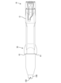
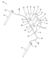
- FIG. 2 is a perspective view of the electrostatic coating gun of the first embodiment as viewed obliquely downward and forward.
- Top view of electrostatic spray gun Partially enlarged front view of the electrostatic coating gun Partial cutaway side view of electrostatic spray gun
- Front view of electric field control member Plan view of holding member
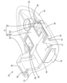
- Plan view showing the state of the electrode unit at the time of manufacture Perspective view of the electrode unit when attached to the holding member, viewed obliquely from above and behind
- FIG. 4 is a perspective view of the state in which the electrode unit is attached to the holding member, viewed obliquely from above and behind; Partially enlarged cross-sectional side view showing the connection structure between the elastic connection member of the gun body and the grounding member of the electric field control member.
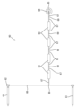
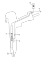
- Explanatory diagram showing the electrical configuration of the electrostatic coating gun The perspective view which looked at the electrostatic coating gun of the present Example 2 from diagonally upper front.
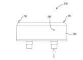
- Plan view of the holding member of the second embodiment FIG. 11 is an exploded perspective view of the holding member of the second embodiment; Explanatory diagram showing the electrical configuration of the electrostatic coating gun of the third embodiment.
- the electrostatic coating gun preferably has an electric field control member attached to the gun body. It is preferable that the electric field control member has the electrode pin and a holding member that holds the electrode pin. According to this configuration, there is no need to provide the gun body with a structure for holding the electrode pin, and the structure of the gun body can be simplified.
- the electric field control member has a resistive element provided on a path between the electrode pin and the ground, and the resistive element is held by the holding member.
- the output current of the discharge electrode is lower than the configuration without the resistance element, and the electric field strength to the coating object is increased, so that the efficiency of coating the charged paint to the coating object can be improved. can.
- the resistive element is held by the holding member and integrated as the electric field control member, the output current of the discharge electrode can be adjusted by attaching the electric field control member with the number and type of resistive elements adjusted to the gun body. be able to.
- the electric field control member has a synthetic resin injection-molded portion integrally formed with the holding member, and the resistance element is embedded in the injection-molded portion. According to this configuration, it is possible to ensure the insulation of the resistance element.
- the output current of the discharge electrode can be adjusted not only by the resistive element but also by the variable resistor.
- the electric field control member has an injection-molded portion made of synthetic resin formed integrally with the holding member, and the injection-molded portion includes the electrode pins of the electrode unit including the electrode pins. At least a portion of the portion other than the front end portion is preferably embedded.
- the "embedded" form includes a form that is embedded inside the injection-molded part and is not exposed from the outer surface of the injection-molded part, and a form that is exposed to the outer surface of the injection-molded part but does not protrude from the outer surface of the injection-molded part. including. According to this configuration, at least a portion of the portion of the electrode unit excluding the front end portion of the electrode pin is embedded in the injection molded portion.
- the injection pressure causes the synthetic resin material to adhere to the electrode unit, so there is no gap between the injection molded part and the electrode unit. As a result, it is possible to prevent a ground fault from occurring at a portion of the electrode unit other than the electrode pin during electrostatic coating.
- the holding member covers only a part of the outer peripheral surface of the gun body in the circumferential direction. According to this configuration, compared to a configuration in which the holding member covers the entire outer peripheral surface of the gun body, operability is improved due to the reduction in size and weight, and material costs can be reduced.
- the holding member is formed with an electrode holding portion for holding the electrode pin. According to this configuration, it is possible to prevent the electrode pin from being displaced due to the injection pressure in the injection molding process.
- the electrode unit includes a resistive element
- the holding member is formed with a resistive holding portion that holds the resistive element in a positioned state. According to this configuration, it is possible to prevent the resistance element from being displaced due to the injection pressure in the injection molding process.
- the electrode unit includes a grounding member connectable to an elastic connection member for grounding provided on the gun body, and an exposed portion of the grounding member on the outer surface of the injection-molded portion is provided on the outer surface of the injection-molded portion. It is preferable that a surrounding seal portion is integrally formed, and the seal portion is in liquid-tight contact with the gun body. According to this configuration, it is possible to prevent the connection portion between the elastic connection member and the ground member from being exposed to water without providing a seal member separate from the injection molded portion.
- the holding member has an engaging portion that is pivotably fitted to the gun body, and a fixing portion that is fixed to the gun body by a fastening member. According to this configuration, compared to the case where the holding member is attached to the gun body using a plurality of fastening members, only one fixing portion can be fixed by the fastening member. As a result, workability is improved when attaching the holding member to the gun body.
- the gun body is provided with an elastic connecting member for grounding
- the holding member is provided with a grounding member connected to the elastic connecting member when the holding member is attached to the gun body
- the grounding member is preferably formed with a contact surface with which the elastic connection member is brought into contact with the elastic connection member in an elastically deformed state.
- a continuous surface forming an obtuse angle with respect to the outer peripheral surface of the gun body is preferably formed on the outer surface of the holding member.
- FIG. 1, 2, 4, 7, and 12 is defined as front in the following description.
- 1, 3 to 6, 8, 9, 11, 13 to 15 are defined as upward and downward.
- the electrostatic coating gun of Example 1 is used when performing electrostatic coating using powder coating, and is applied to a hand gun that is held by an operator to perform coating.
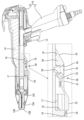
- the electrostatic coating gun is configured by assembling a gun body 10 and an electric field control member 30.
- the gun body 10 has a vertically long grip 11 to be gripped by an operator, and a body 12 that extends in the front-rear direction and continues from the upper end of the grip 11 .
- a trigger 13 is provided on the grip 11 .
- the body 12 accommodates a high voltage generator 14 that generates a high voltage.
- the high voltage generator 14 converts an AC voltage input from the power supply 90 (see FIG. 16) side into a high voltage DC voltage and outputs the high voltage DC voltage.
- the high voltage generator 14 has a transformer, a booster circuit, and an output resistor.
- the booster circuit is composed of, for example, a Cockcroft-Walton type booster rectifier circuit.
- the booster circuit boosts and rectifies the AC voltage input from the transformer to convert it into a high DC voltage.
- the output side of the booster circuit is connected to the output resistor, for example by a metal wire.
- the front end of the body 12 is provided with a nozzle 15A, a nozzle cap 15B, a cap nut 15C, and a discharge electrode 15D.
- the nozzle 15A sprays the paint supplied to the gun body 10 to the outside.
- the nozzle cap 15B is connected to the body 12 via a cap nut 15C and covers the front end side of the nozzle 15A.
- the discharge electrode 15D is made of metal, for example, and has a pin shape. The pin shape also includes a needle shape.
- the output resistor of the high voltage generator 14 is connected to the discharge electrode 15D, and the high voltage output from the high voltage generator 14 is applied to cause corona discharge at the tip of the discharge electrode 15D. Ions of the same polarity as the high voltage are produced.
- the ions generated near the discharge electrode 15D charge the paint sprayed from the nozzle 15A.
- a mounting portion 16 for mounting the electric field control member 30 is provided on the outer peripheral surface of the body 12 .
- the mounting portion 16 is arranged in the front-rear direction central portion of the lower surface side region of the body 12 .
- a front end portion of the mounting portion 16 forms a symmetrical mounting recess 17 formed by recessing a semi-circumferential area of the lower surface of the body 12 .
- the front end of the inner surface of the mounting portion 16 (mounting recess 17 ) in the outer peripheral surface of the body 12 functions as a stopper 18 forming a right angle with the lower surface (outer peripheral surface) of the body 12 .
- a laterally elongated slit-like locking hole 19 is formed in the circumferential central portion of the stopper 18 (lowermost end portion of the stopper 18).
- a female threaded hole 20 is formed at the rear end of the mounting portion 16 with its axis directed vertically. The axial direction of the female screw hole 20 is perpendicular to the opening direction of the locking hole 19 in the stopper 18 .
- a rectangular opening 21 that communicates the inside and outside of the body 12 is formed in the front-rear direction central portion of the mounting portion 16 (between the locking hole 19 and the female screw hole 20) (see FIG. 15).
- the opening 21 opens in a region biased to the right side of the central portion of the body 12 and the mounting portion 16 in the left-right direction.
- an elastic connection member 22 provided inside the body 12 is exposed through the opening 21 .
- the elastic connection member 22 is composed of a compression coil spring with its axis directed vertically.
- the elastic connection member 22 is connected to a ground portion (not shown) at the rear end of the gun main body 10 (body 12) via a crimp terminal 23 and an electric wire 24.
- the grounding portion is made of a conductive resin material and is grounded via a grounding conductive path (not shown) in the grip 11 .
- a rectangular area surrounding the opening 21 of the lower surface of the mounting portion 16 functions as a sealing surface 25 .
- the electric field control member 30 is obtained by integrating the case 31 and the electrode unit 60 .
- the case 31 is composed of a holding member 32 made of synthetic resin and an injection-molded portion 55 integrated with the holding member 32 as a molded part by injection molding.
- the holding member 32 is a member molded as a single piece having a curved portion 33 and a dish-shaped portion 40 projecting rearwardly from the curved portion 33 .
- the holding member 32 is made of a synthetic resin material with high heat resistance.
- the curved portion 33 When viewed from the front of the holding member 32, the curved portion 33 has an arcuate shape that bulges downward.
- the outer peripheral surface of the curved portion 33 in a front view has a semicircular arc shape.
- the radius of curvature of the outer peripheral surface of the curved portion 33 is slightly larger than the radius of curvature of the front adjacent region 26 (see FIGS. 1 and 4) of the outer peripheral surface of the body 12 adjacent to the front end of the mounting portion 16 .
- a locking portion 34 projecting forward in a plate-like shape is formed at the lower end portion (central portion of the curved portion 33 in the circumferential direction) of the front surface of the curved portion 33 .
- the curved portion 33 is formed with a box portion 35 .
- the box portion 35 is composed of a pair of laterally symmetrical side plate portions 36 rising upward from the inner peripheral surface of the curved portion 33, and a horizontal upper plate portion 37 formed by connecting the upper edges of the both side plate portions 36 to each other. .
- the inside of the box portion 35 is open at both front and rear end faces.
- a pair of left-right symmetrical electrode holding portions 38 are formed at both ends of the curved portion 33 in the circumferential direction.
- the electrode holding portion 38 projects radially outward (lateral direction) and has a rib-like shape extending in the front-rear direction.
- Electrode holding holes 39 are formed in the left and right electrode holding portions 38 so as to pass through the electrode holding portions 38 in the front-rear direction.
- the horizontal distance between the pair of symmetrical electrode holding holes 39 is larger than the diameter of the front adjacent region 26 of the body 12 .
- the dish-shaped portion 40 has a symmetrical shape and a shovel shape with a pointed rear end.
- the maximum width dimension (horizontal dimension) of the dish-shaped portion 40 is smaller than the width dimension of the curved portion 33 .
- the outer surface of the dish-shaped portion 40 is composed of a flat horizontal lower surface portion 41 , a pair of symmetrical side continuous surfaces 42 , and a rear continuous surface 43 .
- the side continuous surfaces 42 extend obliquely upward and outward from the left and right side edges of the lower surface portion 41 .
- the rear continuous surface 43 is a curved surface with a small curvature and extends obliquely upward and rearward from the rear end of the lower surface portion 41 .
- the rear continuous surface 43 continues to the rear edge of the lower surface portion 41 and the rear edges of the left and right side continuous surfaces 42 .
- the rear continuous surface 43 (the rear end region of the dish-shaped portion 40) has a shape that gradually narrows toward the rear end.
- a housing recess 44 is formed in the front end of the dish-shaped part 40 by recessing the upper surface of the dish-shaped part 40 . In the front-rear direction, the accommodation recess 44 is formed only in a region behind the rear end of the electrode holding hole 39 .
- a front wall of the housing recess 44 is formed by the curved portion 33 .
- a rear wall of the housing recess 44 is formed by a partition wall portion 45 .
- Left and right side walls of the housing recess 44 are formed by left and right side wall portions 46 having side continuous surfaces 42 .
- a pair of left and right lead wire holding portions 47 are formed in the housing recess 44 .
- the pair of lead wire holding portions 47 are arranged with an interval in the left-right direction, and rise upward from a position near the rear surface of the curved portion 33 (the front surface of the accommodation recess 44 ) in the bottom surface of the accommodation recess 44 .
- a holding portion 48 for resistance is formed in the housing recess 44 so as to protrude upward from the bottom surface of the housing recess 44 .
- a plurality (four in the first embodiment) of resistance holding grooves 49 are formed in the resistance holding portion 48 so as to be aligned in the left-right direction.
- the resistance holding groove 49 is open to the upper surface and both front and rear surfaces of the resistance holding portion 48 .
- the resistance holding groove 49 has an inner peripheral surface whose front view shape is a major arc.
- a grounding holding portion 50 is formed in the housing recess 44 so as to protrude upward from the bottom surface of the housing recess 44 .
- the ground holding portion 50 is composed of a pair of left-right symmetrical ground holding projections 51 arranged concentrically in an arc shape in a plan view.
- a pair of front and rear notch portions 52 are formed between the pair of earth holding projections 51 by cutting downward from the upper end of the earth holding portion 50 .
- a cylindrical fixing portion 53 is formed at the rear end portion of the dish-shaped portion 40 with its axis directed vertically.
- a through-hole 54 is formed in the hollow interior of the fixed portion 53 so as to pass vertically through the dish-shaped portion 40 (holding member 32 ).
- the fixing portion 53 is arranged at the rear end portion of the lower surface portion 41 .
- the fixing portion 53 and the locking portion 34 are arranged in the center of the holding member 32 in the left-right direction.
- the fixing portion 53 and the locking portion 34 are arranged in a positional relationship separated from each other in the front-rear direction.
- the injection molded part 55 is provided for the purpose of ensuring insulation of the electrode unit 60, and is made of an insulating hot-melt adhesive or a two-liquid resin.
- the injection molded portion 55 has a first molded portion 56 and a pair of symmetrical second molded portions 57 .
- the first molded portion 56 is a portion of the injection molded portion 55 that is housed within the housing recess 44 .
- the first molded portion 56 has a form in which the entire accommodation recess 44 is filled.
- the upper surface of the first molding portion 56 is continuous with the upper surface of the upper plate portion 37 of the box portion 35 and the upper surface of the partition wall portion 45 at the same height.
- the entire lead wire holding portion 47 , the entire resistance holding portion 48 , and the entire ground holding portion 50 are embedded inside the first molded portion 56 .
- a pair of symmetrical seal portions 58 are formed on the upper surface of the first molded portion 56 .
- the seal portion 58 has a shape protruding from the upper surface of the first molded portion 56 .
- the shape of the seal portion 58 in a plan view is a rectangular frame shape with long sides oriented in the front-rear direction.
- the right seal portion 58 is arranged to surround the ground holding portion 50 in plan view.
- the pair of left and right second molded portions 57 are configured to rise upward from the rear end portion of the first molded portion 56 along the rear of the curved portion 33 .
- the electrode unit 60 includes a pair of symmetrical electrode pins 61, a plurality of (four in the first embodiment) resistive elements 63, one grounding member 64, and one and a long lead wire 68 made of metal.
- the electrode pin 61 is a metal component elongated in the front-rear direction.
- the electrode pin 61 is pin-shaped.
- the pin shape also includes a needle shape.
- the front end of the electrode pin 61 is arranged behind the front end of the discharge electrode 15D.
- a circular large-diameter portion 62 having an increased diameter is formed at the rear end portion of the electrode pin 61 .
- the resistance element 63 has a cylindrical shape with its axis extending in the front-rear direction.
- the grounding member 64 is a cylindrical metal component with its axis directed vertically.
- a circular enlarged diameter portion 65 having a larger diameter is formed at the upper end portion of the ground member 64 .
- the upper surface of the enlarged diameter portion 65 functions as a contact surface 66 .
- Each resistance element 63 has a pair of short lead wires 67 extending in the front-rear direction from its front and rear ends.
- the ground member 64 has one short lead wire 67 extending radially outward. Both the long lead wire 68 and the short lead wire 67 are plastically deformable, and have a shape retainability of holding a constant shape due to the rigidity of the lead wires 67 and 68 themselves.
- the pair of electrode units 60 are arranged with a space left and right facing in the front-rear direction.
- the rear ends (large-diameter portions 62 ) of both electrode pins 61 are connected to each other via a conductive path composed of a long linear lead wire 68 .
- the plurality of resistive elements 63 are arranged in series in the front-rear direction behind the electrode pin 61 .
- the grounding member 64 is arranged in line with the row of the resistance elements 63 behind the rearmost resistance element 63 .
- the pair of electrode pins 61 and the foremost resistance element 63 are connected via a conductive path formed by fixing a long lead wire 68 and a short lead wire 67 of the foremost resistance element 63 by welding 69 in a T-shape.
- Adjacent resistive elements 63 are connected to each other via conductive paths in which the short lead wires 67 of the adjoining resistive elements 63 are fixed in a straight line by welding 69 .
- the resistance element 63 at the rearmost end and the grounding member 64 are connected via a conductive path in which the short lead wire 67 of the resistance element 63 and the short lead wire 67 of the grounding member 64 are fixed by welding 69 in a straight line.
- the electrode pin 61, the resistance element 63, and the grounding member 64 are arranged so as to match the positions of the electrode holding portion 38, the resistance holding portion 48, and the grounding holding portion 50, respectively.
- the pair of electrode pins 61 are arranged parallel to each other with a space left and right.
- the plurality of resistive elements 63 are arranged in parallel in the left-right direction with the short lead wires 67 extending in the front-rear direction.
- a plurality of parallel resistor elements 63 are arranged diagonally below and behind the pair of electrode pins 61 and arranged between the pair of electrode pins 61 in the left-right direction.
- the ground member 64 is arranged near the right side of the row of the resistance elements 63 .
- a pair of arcuate portions 68 ⁇ /b>A connected to the electrode pin 61 are formed by plastically deforming them in an arcuate shape along the curved portion 33 .
- a region of the long lead wire 68 between the pair of arcuate portions 68A is a linear portion 68L.
- the conductive paths (short lead wires 67) connecting the resistive elements 63 are plastically deformed so as to form a "U" shape in plan view.
- the conductive path (short lead wire 67) connecting the resistance element 63 located at the rearmost end in FIG. 10 and the grounding member 64 is plastically deformed to form an "L shape".
- the electrode unit 60 deformed into the above configuration is temporarily assembled to the holding member 32 as shown in FIGS.
- the electrode pin 61 is inserted into the electrode holding hole 39 from the rear side of the electrode holding portion 38 and penetrated, and the large diameter portion 62 is brought into contact with the front surface of the curved portion 33 .
- the electrode pin 61 is positioned vertically and horizontally with respect to the holding member 32 and is positioned so as not to move relative to the front. Only the front end portion of the electrode pin 61 protrudes in front of the electrode holding portion 38 .
- the arcuate portion 68A of the long lead wire 68 is arranged along the rear surface of the curved portion 33.
- a base end portion of the arcuate portion 68A of the elongated lead wire 68 that continues to the linear portion 68L is accommodated in the accommodation recess 44 .
- the entire linear portion 68L is also accommodated within the accommodation recess 44 .
- Both left and right ends of the linear portion 68L are positioned so as to be sandwiched between the rear surface of the curved portion 33 and the lead wire holding portion 47 in the front-rear direction.
- the plurality of resistance elements 63 are individually press-fitted into the plurality of resistance holding grooves 49 from above the resistance holding portion 48 .
- the resistance element 63 is positioned with respect to the holding member 32 in the up-down direction, the left-right direction, and the front-rear direction.
- the grounding member 64 is press-fitted between the pair of grounding holding projections 51 from above the grounding holding portion 50 , and the enlarged diameter portion 65 is brought into contact with the upper ends of the grounding holding projections 51 .
- the plurality of short lead wires 67 are arranged forward or rearward of the holding portion 48 for resistance.
- the resistance element 63 , the grounding member 64 and the plurality of short lead wires 67 are housed in the housing recess 44 .
- the holding member 32 temporarily assembled with the electrode unit 60 is set in a mold for injection molding (not shown). Inside the mold, there are a cavity (not shown) formed by the housing recess 44, a cavity (not shown) formed between the curved portion 33 and the mold, and an internal space of the box portion 35. A cavity (not shown) is secured. A molten insulating hot-melt adhesive or two-component resin is injected under pressure into these cavities.
- the hot-melt adhesive or two-liquid resin injected under pressure is filled between the holding member 32 and the parts 61, 62, 63, 64, 67 constituting the electrode unit 60 by the injection pressure, and the electrodes are formed.
- the entire parts constituting the unit 60 are in close contact with each other without gaps.
- Hot melt adhesives or two-part resins cure in a short time.
- the injection-molded portion 55 is integrated with the holding member 32, and the case 31 (the holding member 32 and the injection-molded portion 55) and the electrode unit 60 are formed. are integrated. Thus, the manufacture of the electric field control member 30 is completed.
- the electrode unit 60 is embedded in the injection-molded portion 55 .
- the electrode pin 61 only the large diameter portion 62 is embedded in the injection molded portion 55 , but most of the electrode pin 61 ahead of the large diameter portion 62 is located outside the injection molded portion 55 .
- the grounding member 64 the upper surface (contact surface 66 ) of the enlarged diameter portion 65 is exposed on the upper surface of the injection molded portion 55 , but the entire grounding member 64 including the enlarged diameter portion 65 is located on the injection molded portion 55 . embedded inside.
- the front ends of the left and right electrode pins 61 project forward from the electrode holding holes 39 (the electrode holding portions 38).
- the electrode unit 60 Since the hot-melt adhesive or two-liquid resin is injected under pressure, there is concern that the electrode unit 60 may be misaligned due to the injection pressure. However, since the electrode pin 61 is inserted into the electrode holding hole 39 and the large diameter portion 62 is in contact with the rear surface of the curved portion 33 , the electrode pin 61 is not displaced from the holding member 32 . Since the long lead wire 68 is sandwiched between the rear surface of the curved portion 33 and the lead wire holding portion 47 , the long lead wire 68 is not displaced in the front-rear direction with respect to the holding member 32 . Since the resistance element 63 is press-fitted into the resistance holding groove 49 , the position of the resistance element 63 does not shift with respect to the holding member 32 . Since the grounding member 64 is elastically sandwiched between the grounding holding projections 51 , the position of the grounding member 64 does not shift with respect to the holding member 32 .
- the electric field control member 30 manufactured as described above is attached to the gun body 10 .
- the attitude of the electric field control member 30 is tilted so that the upper surface of the injection molded portion 55 is lowered toward the rear, and the locking portion 34 at the front end of the holding member 32 is aligned with the locking hole 19 of the gun body 10 . and insert it obliquely from the bottom rear.
- the electric field control member 30 can swing vertically with respect to the gun body 10 with the locking portion between the locking portion 34 and the locking hole 19 as a fulcrum.
- the electric field is controlled with the fitting portion of the locking portion 34 and the locking hole 19 (the upper edge of the opening edge of the locking hole 19) as a fulcrum.
- Lift member 30 the enlarged diameter portion 65 of the ground member 64 is brought into contact with the lower end of the elastic connection member 22, and the elastic connection member 22 is pushed up by the contact surface 66 (upper surface) of the enlarged diameter portion 65 to elastically contract in the vertical direction. Since the outer diameter dimension of the enlarged diameter portion 65 is larger than the outer diameter dimension of the elastic connecting member 22, the enlarged diameter portion 65 and the elastic connecting member 22 can be reliably brought into contact with each other.
- the grounding member 64 is connected to the grounding 91 (see FIG. 16) via the elastic connecting member 22 . That is, the resistance element 63 described above is provided between the electrode pin 61 and the ground 91 as shown in FIG. Since the resistance element 63 is provided between the electrode pin 61 and the ground 91, the output current of the discharge electrode 15D is lowered and the electric field intensity to the object to be coated is increased compared to the configuration without the resistance element 63. Therefore, the efficiency of applying the charged paint to the object to be painted can be improved. Moreover, since the resistance element 63 is held by the holding member 32 and integrated as the electric field control member 30, by attaching the electric field control member 30 with the number and type of the resistance elements 63 adjusted to the gun body 10, the discharge electrode 15D output current can be adjusted.
- the through hole 54 of the fixing portion 53 faces the female threaded hole 20 of the gun body 10 vertically.
- the screw 70 is inserted into the through hole 54 from below the holding member 32 and screwed into the female screw hole 20 of the gun body 10 .
- the seal portion 58 is brought into liquid-tight contact with the seal surface 25 while being elastically deformed. Since the opening 21 of the gun body 10 is sealed by the right sealing portion 58, entry of foreign matter (powder paint) into the gun body 10 through the opening 21 is prevented.
- the left seal portion 58 is brought into close contact with the lower surface of the mounting portion 16 of the gun body 10, so that the holding member 32 (electric field control member 30) with respect to the gun body 10 is laterally moved. Prevents tilting.
- the dish-shaped portion 40 covers the rear end region of the mounting portion 16 of the gun body 10 and the curved portion 33 is fitted into the mounting recess 17 .
- the screw 70 is completely tightened, the process of attaching the electric field control member 30 to the gun body 10 is completed.
- the electric field control member 30 is attached to the body 12 at a position behind the nozzle 15A (in the direction opposite to the direction in which the powder coating material is discharged from the nozzle 15A).
- the front end portions of the pair of left and right electrode pins 61 protrude (expose) forward of the holding member 32 (electrode holding portion 38) behind the nozzle 15A. It has become.
- the pair of electrode pins 61 are positioned near the outer peripheral surface of the gun body 10 and arranged to sandwich the gun body 10 from both left and right sides.
- the powder coating supplied to the gun body 10 is discharged forward from the nozzle 15A while being charged by the high voltage generator 14.
- the powder paint discharged from the nozzle 15A is applied to the surface to be coated by an electric field generated between the nozzle 15A and the surface to be coated (not shown).
- the electric field control member 30 generates an electric field for absorbing free ions between the nozzle 15A and the electrode pin 61 while electrostatic coating is being performed.
- the electric field generated by the electric field control member 30 reduces the amount of free ions in the powder layer of the powder coating applied to the surface to be coated. As a result, the reverse ionization phenomenon (electrostatic repulsion) caused by free ions remaining in the powder layer is suppressed, and the smoothness of the coating film is maintained.
- the electrostatic coating gun of the first embodiment includes a gun body 10 and an electric field control member 30.
- a nozzle 15A is provided at the front end of the gun body 10 for discharging the powder coating material forward.
- the electric field control member 30 is attached to the outer peripheral surface of the gun body 10 at a position behind the nozzle 15A.
- the electric field control member 30 has a plurality of electrode pins 61 that generate an electric field between themselves and the nozzle 15A, and a holding member 32 that holds the plurality of electrode pins 61 spaced apart in the circumferential direction.
- the holding member 32 that holds the plurality of electrode pins 61 has a form that covers only a part of the outer peripheral surface of the gun body 10 in the circumferential direction. Compared to a ring-shaped holding member (not shown) that covers the entire outer peripheral surface of the gun body, the holding member 32 (electric field control member 30) of the first embodiment can be made smaller. Since the holding member 32 is the only part that holds the electrode pin 61, the number of parts can be reduced compared to the case where the electrode pin 61 is held by two parts.
- the electric field control member 30 has an injection-molded portion 55 made of synthetic resin formed integrally with the holding member 32 .
- the electrode unit 60 includes electrode pins 61 . At least a portion of the electrode unit 60 excluding the front end portion of the electrode pin 61 is embedded in the injection molded portion 55 .
- the "embedded" mode includes a mode in which the injection-molded portion 55 is embedded and is not exposed from the outer surface of the injection-molded portion 55, and a mode in which the injection-molded portion 55 is exposed to the outer surface but the injection-molded portion 55 is exposed. and forms that do not protrude from the outer surface.
- the injection pressure causes the synthetic resin material (hot melt adhesive or two-liquid resin) to adhere to the electrode unit 60, so that the gap between the injection molded portion 55 and the electrode unit 60 is reduced. does not occur. As a result, it is possible to prevent a ground fault from occurring at a portion of the electrode unit 60 other than the electrode pin 61 during electrostatic coating.
- the electrode unit 60 includes an electrode pin 61, a resistive element 63 and a ground member 64. Since the holding member 32 is formed with the electrode holding portion 38 for holding the electrode pin 61, it is possible to prevent the electrode pin 61 from being displaced due to the injection pressure in the injection molding process. Since the holding member 32 is formed with the resistance holding portion 48 that holds the resistance element 63 in a positioned state, it is possible to prevent the resistance element 63 from being displaced due to the injection pressure in the injection molding process. Since the holding member 32 is formed with the grounding holding portion 50 that holds the grounding member 64 in a positioned state, it is possible to prevent the grounding member 64 from being displaced due to the injection pressure in the injection molding process.
- the electrode unit 60 includes a grounding member 64 that can be connected to the grounding elastic connection member 22 provided on the gun body 10 .
- a contact surface 66 of the ground member 64 is exposed on the outer surface of the injection molded portion 55 .
- a sealing portion 58 is integrally formed on the outer surface of the injection-molded portion 55 to surround the exposed portion (contact surface 66 ) of the ground member 64 on the outer surface of the injection-molded portion 55 .
- the seal portion 58 is in liquid-tight contact with the gun body 10 . According to this configuration, even if the sealing portion 58 which is separate from the injection molded portion 55 is not provided, the connecting portion between the elastic connecting member 22 and the grounding member 64 is not exposed to water, and foreign matter is prevented from entering the gun body 10 . Intrusion can be prevented.
- the holding member 32 has a locking portion 34 that is pivotably fitted to the gun body 10, and a fixing portion 53 that is fixed to the gun body 10 by a fastening member (a screw 70). According to this configuration, compared to the case where the holding member 32 is attached to the gun body 10 using a plurality of fastening members, only one fixing portion 53 is fixed by the fastening member (the screw 70). . Thereby, workability when attaching the holding member 32 to the gun body 10 is good.
- the gun body 10 is provided with an elastic connecting member 22 for grounding.
- the holding member 32 is provided with a grounding member 64 that is connected to the elastic connecting member 22 when the holding member 32 is attached to the gun body 10 .
- the ground member 64 is formed with a contact surface 66 with which the elastic connecting member 22 is brought into contact with the elastic connecting member 22 in an elastically deformed state.
- the outer diameter dimension of the contact surface 66 is larger than the outer diameter dimension of the elastic connecting member 22 . According to this configuration, the elastic connection member 22 can be connected to the ground member 64 simply by bringing it into contact with the contact surface 66 while being elastically deformed, so workability is good.
- a side continuous surface 42 and a rear continuous surface 43 are formed on the outer surface of the holding member 32 so as to form an obtuse angle with the outer peripheral surface of the gun body 10 .
- the side continuous surface 42 is continuous with the side area of the outer peripheral surface of the body 12 without a groove, gap, recess, or the like.
- the rear continuous surface 43 is continuous with the bottom surface area of the outer peripheral surface of the body 12 without a groove, gap, dent, or the like.
- Example 2 The shape of the electric field control member is not limited to that of the first embodiment.
- the electric field control member is ring-shaped.
- the second embodiment will be described below with reference to FIGS. 17 to 19.
- FIG. the same reference numerals are assigned to the same configurations as those of the first embodiment, and detailed description thereof will be omitted.
- the electrostatic coating gun of Example 2 includes a gun body 210, as shown in FIG.
- the gun body 210 has a grip 11 and a body 212 .
- Inside the body 212 like the body 12 of the first embodiment, the high voltage generator 14, the discharge electrode 15D and the like are provided.
- An electric field control member 230 is attached to the outer circumference of the body 212 .
- the electric field control member 230 has a holding member 232, a pair of left and right electrode pins 261, a resistive element 263, a ground member 264, and lead wires 268.
- a pair of electrode pins 261 are provided on one end side of the lead wire 268 with a space therebetween, and a grounding member 264 is provided on the other end side of the lead wire 268 .
- a resistance element 263 is provided between the member 264 and the member 264 .
- the ground member 264 is connected to the ground 91 (see FIG. 16). That is, the resistive element 263 is provided between the electrode pin 261 and the ground 91 .
- the holding member 232 is made of synthetic resin and has an annular shape, specifically an annular shape.
- the holding member 232 has an annular inner member 281 and an annular outer member 282 arranged outside the inner member 281 .
- the inner member 281 has an annular portion 283 and a flange portion 284 extending radially outward from one axial end of the annular portion 283 .
- the outer member 282 is fitted from the other axial end side of the inner member 281 and screwed to the flange portion 284 .
- a portion of the pair of left and right electrode pins 261 excluding the front end portions and a resistance element 263 are arranged.
- the resistance element 263 is held by the holding member 232 .
- the front ends of the pair of left and right electrode pins 261 are exposed outside the holding member 232 as shown in FIGS. 17 and 18 .
- a resin injection port 285 is formed in the outer member 282 of the holding member 232, as shown in FIGS.
- a resin molded portion (not shown) is formed in the holding member 232 by injecting resin from the resin injection port 285 .
- Parts of the resistor element 263 and the electrode pin 261 excluding the front end part are embedded in the resin molded part.
- the holding member 232 is attached to the gun body 210 as shown in FIG.
- Example 3 a configuration provided with a variable resistor 71 will be described with reference to FIG. In the following description, the same reference numerals are assigned to the same configurations as those of the first embodiment, and detailed description thereof will be omitted.
- a variable resistor 71 is provided between the resistive element 63 and the ground 91. According to this configuration, the output current of the discharge electrode 15 ⁇ /b>D can be adjusted not only by the resistance element 63 but also by the variable resistor 71 .
- the seal portion is formed integrally with the injection-molded portion as means for preventing the connection portion between the elastic connection member and the ground member from being exposed to water. may be used to prevent the connecting portion between the elastic connecting member and the grounding member from being exposed to water.
- the holding member is attached to the gun body by one engaging portion and one fixing portion. A fixed part may be provided.
- attachment of the holding member to the gun body and connection of the grounding member to the elastic connecting member can be performed in one action. The connection may be made in a separate operation.
- the number of electrode pins is two, but the number of electrode pins may be one or three or more.
- the electrostatic coating gun applied to a hand gun that is held by an operator for coating has been described, but the present invention can also be applied to an automatic gun attached to a reciprocator or a robot. can be done.
Landscapes
- Electrostatic Spraying Apparatus (AREA)
Priority Applications (3)
| Application Number | Priority Date | Filing Date | Title |
|---|---|---|---|
| CN202180103669.1A CN118159364A (zh) | 2021-12-17 | 2021-12-17 | 静电涂装枪 |
| PCT/JP2021/046796 WO2023112319A1 (ja) | 2021-12-17 | 2021-12-17 | 静電塗装ガン |
| JP2023567488A JP7621691B2 (ja) | 2021-12-17 | 2021-12-17 | 静電塗装ガン |
Applications Claiming Priority (1)
| Application Number | Priority Date | Filing Date | Title |
|---|---|---|---|
| PCT/JP2021/046796 WO2023112319A1 (ja) | 2021-12-17 | 2021-12-17 | 静電塗装ガン |
Publications (1)
| Publication Number | Publication Date |
|---|---|
| WO2023112319A1 true WO2023112319A1 (ja) | 2023-06-22 |
Family
ID=86773976
Family Applications (1)
| Application Number | Title | Priority Date | Filing Date |
|---|---|---|---|
| PCT/JP2021/046796 Ceased WO2023112319A1 (ja) | 2021-12-17 | 2021-12-17 | 静電塗装ガン |
Country Status (3)
| Country | Link |
|---|---|
| JP (1) | JP7621691B2 (https=) |
| CN (1) | CN118159364A (https=) |
| WO (1) | WO2023112319A1 (https=) |
Citations (4)
| Publication number | Priority date | Publication date | Assignee | Title |
|---|---|---|---|---|
| JP2006082064A (ja) * | 2004-09-17 | 2006-03-30 | Toyota Motor Corp | 静電塗装装置 |
| WO2008038035A1 (en) * | 2006-09-27 | 2008-04-03 | Yu Tung Investment Holdings Limited | Powder spray coating discharge assembly |
| WO2009069396A1 (ja) * | 2007-11-30 | 2009-06-04 | Abb K.K. | 静電塗装装置 |
| JP2015166073A (ja) * | 2014-03-04 | 2015-09-24 | 旭サナック株式会社 | 静電塗装装置 |
Family Cites Families (3)
| Publication number | Priority date | Publication date | Assignee | Title |
|---|---|---|---|---|
| JPS62190649U (https=) * | 1986-05-27 | 1987-12-04 | ||
| JPS63162056A (ja) * | 1986-12-24 | 1988-07-05 | Trinity Ind Corp | 静電塗油機 |
| US7748651B2 (en) * | 2003-03-27 | 2010-07-06 | Asahi Sunac Corporation | Electrostatic coating spray gun |
-
2021
- 2021-12-17 CN CN202180103669.1A patent/CN118159364A/zh active Pending
- 2021-12-17 JP JP2023567488A patent/JP7621691B2/ja active Active
- 2021-12-17 WO PCT/JP2021/046796 patent/WO2023112319A1/ja not_active Ceased
Patent Citations (4)
| Publication number | Priority date | Publication date | Assignee | Title |
|---|---|---|---|---|
| JP2006082064A (ja) * | 2004-09-17 | 2006-03-30 | Toyota Motor Corp | 静電塗装装置 |
| WO2008038035A1 (en) * | 2006-09-27 | 2008-04-03 | Yu Tung Investment Holdings Limited | Powder spray coating discharge assembly |
| WO2009069396A1 (ja) * | 2007-11-30 | 2009-06-04 | Abb K.K. | 静電塗装装置 |
| JP2015166073A (ja) * | 2014-03-04 | 2015-09-24 | 旭サナック株式会社 | 静電塗装装置 |
Also Published As
| Publication number | Publication date |
|---|---|
| JPWO2023112319A1 (https=) | 2023-06-22 |
| JP7621691B2 (ja) | 2025-01-27 |
| CN118159364A (zh) | 2024-06-07 |
Similar Documents
| Publication | Publication Date | Title |
|---|---|---|
| US7748651B2 (en) | Electrostatic coating spray gun | |
| JP3763893B2 (ja) | 静電塗装噴霧装置 | |
| JP5513061B2 (ja) | 静電塗装システム、および、静電塗装用スプレーガン | |
| JPH0532106B2 (https=) | ||
| AU6953791A (en) | Electrostatic spray gun | |
| US7552882B2 (en) | Spray gun for electrostatic painting | |
| EP2903748B1 (en) | Spray tip assembly for electrostatic spray gun | |
| US9498785B2 (en) | Electrostatic spraying device | |
| WO2023112319A1 (ja) | 静電塗装ガン | |
| JP2002263526A (ja) | コーティング粉体用粉体スプレイガン | |
| CN102939170B (zh) | 静电涂布方法和静电涂布枪 | |
| TWI821827B (zh) | 靜電塗裝噴槍 | |
| JP7107859B2 (ja) | 充電インレットの固定構造 | |
| JP5579515B2 (ja) | 対向電極を設けた静電塗装用スプレーガン | |
| CN113423509A (zh) | 用于喷枪的后部壳体以及具有这种后部壳体的喷枪 | |
| CA2407815C (en) | Coating-powder spray gun | |
| JP5787223B2 (ja) | 静電塗装方法及び静電塗装用ガン | |
| JP2011255276A (ja) | 静電塗装装置 | |
| JP2025181198A (ja) | 静電塗装装置に適用可能な付加部品、及び静電塗装装置 | |
| JP6881053B2 (ja) | イオン発生装置 | |
| JP3686892B2 (ja) | 粉体静電塗装用ガン | |
| JP7572718B2 (ja) | 静電塗装用スプレーガン | |
| JP2007203158A (ja) | 静電塗装用ガン | |
| JP2024018337A (ja) | 静電噴霧装置 | |
| JPS6212419Y2 (https=) |
Legal Events
| Date | Code | Title | Description |
|---|---|---|---|
| 121 | Ep: the epo has been informed by wipo that ep was designated in this application |
Ref document number: 21968232 Country of ref document: EP Kind code of ref document: A1 |
|
| WWE | Wipo information: entry into national phase |
Ref document number: 2023567488 Country of ref document: JP |
|
| WWE | Wipo information: entry into national phase |
Ref document number: 202180103669.1 Country of ref document: CN |
|
| NENP | Non-entry into the national phase |
Ref country code: DE |
|
| 122 | Ep: pct application non-entry in european phase |
Ref document number: 21968232 Country of ref document: EP Kind code of ref document: A1 |