WO2023105812A1 - タイヤ - Google Patents
タイヤ Download PDFInfo
- Publication number
- WO2023105812A1 WO2023105812A1 PCT/JP2022/019975 JP2022019975W WO2023105812A1 WO 2023105812 A1 WO2023105812 A1 WO 2023105812A1 JP 2022019975 W JP2022019975 W JP 2022019975W WO 2023105812 A1 WO2023105812 A1 WO 2023105812A1
- Authority
- WO
- WIPO (PCT)
- Prior art keywords
- tire
- tag
- display
- electronic tag
- color
- Prior art date
- Legal status (The legal status is an assumption and is not a legal conclusion. Google has not performed a legal analysis and makes no representation as to the accuracy of the status listed.)
- Ceased
Links
Images


Classifications
-
- G—PHYSICS
- G06—COMPUTING OR CALCULATING; COUNTING
- G06K—GRAPHICAL DATA READING; PRESENTATION OF DATA; RECORD CARRIERS; HANDLING RECORD CARRIERS
- G06K19/00—Record carriers for use with machines and with at least a part designed to carry digital markings
- G06K19/06—Record carriers for use with machines and with at least a part designed to carry digital markings characterised by the kind of the digital marking, e.g. shape, nature, code
- G06K19/067—Record carriers with conductive marks, printed circuits or semiconductor circuit elements, e.g. credit or identity cards also with resonating or responding marks without active components
- G06K19/07—Record carriers with conductive marks, printed circuits or semiconductor circuit elements, e.g. credit or identity cards also with resonating or responding marks without active components with integrated circuit chips
- G06K19/077—Constructional details, e.g. mounting of circuits in the carrier
- G06K19/07749—Constructional details, e.g. mounting of circuits in the carrier the record carrier being capable of non-contact communication, e.g. constructional details of the antenna of a non-contact smart card
- G06K19/07758—Constructional details, e.g. mounting of circuits in the carrier the record carrier being capable of non-contact communication, e.g. constructional details of the antenna of a non-contact smart card arrangements for adhering the record carrier to further objects or living beings, functioning as an identification tag
- G06K19/07764—Constructional details, e.g. mounting of circuits in the carrier the record carrier being capable of non-contact communication, e.g. constructional details of the antenna of a non-contact smart card arrangements for adhering the record carrier to further objects or living beings, functioning as an identification tag the adhering arrangement making the record carrier attachable to a tyre
-
- B—PERFORMING OPERATIONS; TRANSPORTING
- B60—VEHICLES IN GENERAL
- B60C—VEHICLE TYRES; TYRE INFLATION; TYRE CHANGING; CONNECTING VALVES TO INFLATABLE ELASTIC BODIES IN GENERAL; DEVICES OR ARRANGEMENTS RELATED TO TYRES
- B60C19/00—Tyre parts or constructions not otherwise provided for
-
- B—PERFORMING OPERATIONS; TRANSPORTING
- B60—VEHICLES IN GENERAL
- B60C—VEHICLE TYRES; TYRE INFLATION; TYRE CHANGING; CONNECTING VALVES TO INFLATABLE ELASTIC BODIES IN GENERAL; DEVICES OR ARRANGEMENTS RELATED TO TYRES
- B60C11/00—Tyre tread bands; Tread patterns; Anti-skid inserts
-
- B—PERFORMING OPERATIONS; TRANSPORTING
- B60—VEHICLES IN GENERAL
- B60C—VEHICLE TYRES; TYRE INFLATION; TYRE CHANGING; CONNECTING VALVES TO INFLATABLE ELASTIC BODIES IN GENERAL; DEVICES OR ARRANGEMENTS RELATED TO TYRES
- B60C15/00—Tyre beads, e.g. ply turn-up or overlap
-
- B—PERFORMING OPERATIONS; TRANSPORTING
- B60—VEHICLES IN GENERAL
- B60C—VEHICLE TYRES; TYRE INFLATION; TYRE CHANGING; CONNECTING VALVES TO INFLATABLE ELASTIC BODIES IN GENERAL; DEVICES OR ARRANGEMENTS RELATED TO TYRES
- B60C19/00—Tyre parts or constructions not otherwise provided for
- B60C2019/004—Tyre sensors other than for detecting tyre pressure
Definitions
- This disclosure relates to tires.
- Patent Document 1 describes a pneumatic tire equipped with a transponder.
- the transponder can provide various information about tires and data on tires in use.
- the transponder has a transmitting/receiving function and a memory function and is arranged, for example, in the sidewall portion.
- An identification mark indicating the position of the transponder is provided on the tire outer surface of the sidewall on which the transponder is arranged or on the tire outer surface of the sidewall portion opposite to the sidewall portion on which the transponder is arranged.
- the identification mark indicating the location of the transponder is distinguished from other sites based on color or shape. When the color of the identification mark is different from the color of the outer surface of the tire, any one of color, brightness, and hue may be different.
- the identification mark has a three-dimensional shape, a concave shape that is recessed from the tire outer surface, a convex shape that protrudes from the tire outer surface, or a shape that combines a concave shape and a convex shape is adopted.
- Patent Document 2 describes a method for treating rubber materials, including rubber from rubber-containing products such as tires. Rubber-containing products, such as tires, are said to be processed by separating rubber and other materials.
- JP 2006-056443 A Japanese Patent Publication No. 2013-512134
- an electronic chip (so-called electronic tag or RFID tag, hereinafter simply referred to as an electronic tag) that functions as a transponder may be provided inside or on the inner surface of the tire.
- information about tires can be provided to an external terminal through communication with the electronic chip.
- information related to tire model, distribution and sales, usage history, driving information of vehicles with tires installed, etc. can be grasped, and necessary information at the time of tire recycling (for example, information related to tire constituent materials) can be collected. This makes it easier to manage traceability related to proper disposal and recycling of tires.
- the position of the electronic tag is displayed on the outer surface of the tire, it is convenient because the position where the sensor is held up can be grasped from the display when information is obtained by a terminal device that obtains information from the electronic tag. . In addition, it is convenient because the position of the electronic tag can be known when the electronic tag is separated from the tire in the sorting process for discarding or recycling the tire.
- the electronic tag is embedded inside the tire, it may be necessary to cut out the tire, remove the electronic tag, and sort the tire. Therefore, it is desired to be able to grasp the range where the electronic tag is provided as the position of the electronic tag.
- the present disclosure has been made in view of such circumstances, and its object is to provide a tire that can indicate the range in which an electronic tag is embedded.
- the tire according to the present disclosure for achieving the above object is an electronic tag arranged inside the surface; a display unit indicating the position of the electronic tag, The display unit disposed on said surface; It is formed in a range that includes the projection image of the shape of the electronic tag onto the surface.
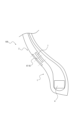
- FIG. 4 is a cross section crossing the circumferential direction of the tire according to the first embodiment, and is a cross-sectional view of a portion including a tag and a display portion.
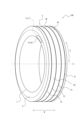
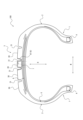
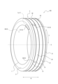
- 1 is a perspective view of a tire according to a first embodiment
- FIG. FIG. 2 is an enlarged cross-sectional view of a side wall portion in the cross-sectional view of FIG. 1
- FIG. 4 is a conceptual diagram showing the positional relationship between a tag and a display section; It is the figure which expanded and displayed the vicinity of the display part arrange
- FIG. 11 is an enlarged cross-sectional view of a sidewall portion of a tire having a display portion according to Modification 1;
- FIG. 11 is an enlarged cross-sectional view of a sidewall portion of a tire provided with a display portion according to Modification 2; It is the figure which expanded and displayed the vicinity of the display part in the sidewall part of another tire.
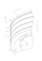
- FIG. 11 is a perspective view of another tire;
- FIG. 1 and 2 show a tire 100 according to this embodiment.
- FIG. 1 shows a cross section of the tire 100 intersecting the circumferential direction C (see FIG. 2).
- FIG. 2 shows a perspective view of the tire 100.
- the tire 100 includes an electronic tag 7 (hereinafter referred to as the tag 7) arranged inside the surface of the tire 100, and a display section 8 indicating the position of the tag 7.
- the tag 7 is a so-called RFID tag, which is an electronic circuit device or electronic chip including an antenna circuit for communication, a memory circuit, and a control circuit.
- the tire 100 will be described in detail below.
- the tire 100 is arranged on the side portion of the tire 100, and includes a bead portion 1 for fixing the tire 100 to the rim, a sidewall portion 2 which is the side portion of the tire 100, and a tread in contact with the road surface. It has part 3.
- the tire 100 is formed in an approximately circular ring centered on the axis G. That is, the tread portion 3, the sidewall portion 2, and the bead portion 1 are approximately circular rings having the axis G as a common center.
- the width direction W, the circumferential direction C (see FIG. 2) and the radial direction R of the tire 100 shown in FIGS. 1 and 2 are the same as the width direction, the circumferential direction and the radial direction of the tread portion 3. .
- the annular outer side is referred to as the radial outer side
- the annular inner side is referred to as the radial inner side.
- the tire 100 has, as internal structures, a carcass 5 that is a cord layer forming the skeleton of the tire 100, a bead core 4 that becomes an internal skeleton of the bead portion 1 and supports the carcass 5, and a surface of the tread portion 3. and the carcass 5, a belt 6 which is a reinforcing band stretched along the circumferential direction C.
- the bead portion 1, sidewall portion 2 and tread portion 3 each contain synthetic rubber.
- the synthetic rubber of the bead portion 1 and the sidewall portion 2 is called side rubber.
- the synthetic rubber of the tread portion 3 is called tread rubber.
- the bead core 4, carcass 5 and belt 6 are embedded in side rubber and tread rubber.
- the radially outer end portions of the sidewall portion 2 are integrally connected to both end portions of the tread portion 3 in the width direction W.
- the bead portion 1 is integrally connected to the radially inner end portion of the sidewall portion 2 . That is, the cross section of the tire 100 intersecting the circumferential direction C has a letter C shape.
- the surface of the tire 100 means the outer surface of the C-shaped arc (hereinafter sometimes referred to as the outer surface) and the inner surface (hereinafter referred to as the inner surface) of the C-shaped arc of the tire 100. may be described as).
- a tread pattern is formed on the tread portion 3 , and a plurality of protrusions 30 (an example of a tread surface) whose outer peripheral surface is in contact with the road surface.
- a plurality of recesses 31 that are recessed radially inward are formed in the inner wall.
- the recess 31 is, for example, a circumferential groove.
- the outer peripheral surface is the radially outer surface of the tread portion 3 in the tire 100 .
- the tire 100 in this embodiment further includes the tag 7 and the display section 8 as described above.
- the cross section of the tire 100 shown in FIG. 1 is the cross section of the tire 100 viewed along the circumferential direction C (see FIG. 2) and shows the cross section of the portion including the tag 7 and the display portion 8 .
- the tag 7 is located inside the tire 100 (inner than the surface) on the side of one sidewall portion 2 near the bead portion 1, and in the width direction W of the tire 100, the carcass 5 ( 2) are arranged outside. That is, the tag 7 is embedded (arranged) in the side portion of the tire 100 .
- the outer side in the width direction W is the same side as the sidewall portion 2 side when viewed from the tread portion 3 .
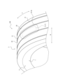
- FIG. 3 shows an enlarged cross-sectional view of the side wall portion 2 in the cross-sectional view shown in FIG.
- the display portion 8 is formed on the sidewall portion 2 .
- the display unit 8 displays a line perpendicular to the outer surface of the sidewall portion 2, which is the outer surface of the tire 100 closest to the tag 7, from the position of the tag 7. It is positioned to intersect the surface. Thereby, the display unit 8 can clearly indicate the range in which the tag 7 is embedded. This makes it easier to remove the tag 7 when the tire 100 is discarded or recycled.
- the position of the tag 7 can be indicated to the operator by the display unit 8, so that the operator can easily locate the tag 7. can be grasped and communication with the tag 7 can be performed smoothly.
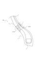
- FIG. FIG. 4 shows a conceptual diagram showing the positional relationship between the tag 7 and the display unit 8 for explaining the installation position of the display unit 8.
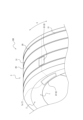
- FIG. 5 is an enlarged view showing the vicinity of the display section 8 arranged on the sidewall section 2 in FIG.
- an orthogonal projection image (an example of a projection image) obtained by projecting the outer shape of the tag 7 onto the outer surface of the sidewall portion 2 is shown as a tag projection image 7s.
- the display portion 8 is formed in a range that includes the outer surface of the sidewall portion 2 and includes the tag projected image 7s.
- the orthogonal projection image of the outer shape of the tag 7 projected onto the surface of the sidewall portion 2, that is, the tag projection image 7s is the surface of the tire 100 closest to the center of the tag 7 (this embodiment It is an image in which the outer shape of the tag 7 is projected onto the surface in the direction along the perpendicular to the outer surface of the tag 7 that is lowered from the center of the tag 7 toward the outer surface of the sidewall portion 2 .
- the display section 8 is preferably formed on the surface of the tire 100 in a range including the tag projection image 7s (see FIGS. 2 and 4). Thereby, the position where the tag 7 is embedded inside the tire 100 in the direction perpendicular to the surface of the tire 100 can be indicated. That is, the tag 7 can be removed from the tire 100 by hollowing out the tire 100 (the sidewall portion 2 in this embodiment) in a direction perpendicular to the surface.
- the display unit 8 includes the tag projection image 7s (see FIGS. 2 and 4) on the surface of the tire 100 and is formed in a wider range than the tag projection image 7s. preferably.
- the tag 7 can be removed more reliably from the tire 100 by hollowing out the range where the display portion 8 is formed. That is, by subjecting the entire range indicated by the display unit 8 to sorting, the tags 7 can be reliably removed.
- the display portion 8 is preferably made of a material having a different color (different color material) from the other portions of the tread portion 3 .
- the display on the display unit 8 can be easily identified by the difference in color.
- the different colors mean that there are differences such as color, tone, brightness, pattern, gloss, etc. that can be visually recognized, that is, that they have identifiability by visual observation.
- Different color materials also include materials that emit light or store light.
- the display section 8 is exemplified by a case where a different color section 87 is formed.
- the different-color material may be obtained by adding a pigment of a different color to the rubber or by removing carbon from the rubber.
- the color is different from that of the other portions of the tread portion 3, so that the position and range can be distinguished by visual observation.
- the embedding depth of the tag 7 may be indicated. This makes it possible to indicate how deep the tag 7 is embedded from the surface of the tire 100 . That is, the tag 7 can be removed from the tire 100 by hollowing out the tire 100 to the depth indicated by the display portion 8 .
- the display portion 8 is yellow, the depth is 1 mm or more and less than 5 mm from the surface, and when the display portion 8 is blue, the depth is 5 mm or more and less than 15 mm from the surface.
- the embedding depth of the tag 7 may be indicated by its shape. For example, when the display part 8 is drawn as a double oval, the depth is 1 mm or more and less than 5 mm from the surface, and when the display part 8 is drawn as a double rectangle, the depth is 5 mm or more and less than 15 mm from the surface. depth, and so on.
- the different-color portion 87 as the display portion 8 may be simply colored on the surface of the tire 100, but as shown in FIG. ) to the inside of the tire 100 .
- the different-color portion 87 as the display portion 8 is preferably formed such that the different-color material has a predetermined thickness in the surface layer portion of the tire 100 and is embedded in the surface layer portion.
- the unique color portion 87 extends from the outer surface of the sidewall portion 2 (the outer surface of the tire 100) to the inside of the tire 100, and is closer to the outer surface than the tag 7 (outer in the width direction W in the present embodiment). is formed over the range of
- the tire 100 according to the second embodiment is the same as the tire 100 according to the first embodiment except for the arrangement of the tag 7 and the display portion 8 .
- the tag 7 is embedded inside the tire 100 in the tread portion 3 and outside the carcass 5 in the radial direction R, as shown in FIGS.
- the display unit 8 displays a line perpendicular to the outer surface of the tread portion 3, which is the outer surface of the tire 100 closest to the tag 7, from the position of the tag 7. It is arranged at a position intersecting with the outer surface.
- a unique color portion 87 as the display portion 8 is arranged over a range that includes the projected tag image 7s (see FIG. 7) and is wider than the projected image 7s. That is, as shown in FIG. 7, the different color portion 87 is arranged over a wider range in the circumferential direction C and width direction W than the projected tag image 7s.
- the different color portion 87 extends in the width direction W over the center convex portion 30 of the tread portion 3 where the tag projected image 7s is located and both concave portions 31 of the convex portion 30 in the width direction W. , are placed.
- the different-color portion 87 as the display portion 8 may be simply colored on the surface of the tire 100, but as shown in FIG. ) to the inside of the tire 100 .
- the different-color portion 87 as the display portion 8 is preferably formed such that the different-color material has a predetermined thickness in the surface layer portion of the tire 100 and is embedded in the surface layer portion.
- the different color portion 87 may be formed thicker than the state shown in FIG. As the different color portion 87 is formed thicker, the distinguishability of the display portion 8 can be maintained even if the tire 100 is worn. For example, the depth from the surface of the convex portion 30 to the inner portion of the tread portion 3 in the radial direction R (inside the tread portion 3) to the bottom portion of the concave portion 31 (the depth from the outer surface in the radial direction R ), the unique color portion 87 may be formed.
- the unique color portion 87 is formed over a range from the outer surface of the tread portion 3 (outer surface of the tire 100) to the inside of the tire 100 and closer to the outer surface than the tag 7 (outer in the radial direction R). It is
- the different-color portion 87 as the display portion 8 is formed from the outer surface of the tire 100 to the inside of the tire 100 and extending from the tag 7 to the outer surface side.
- the unique color portion 87 may be formed over a range that includes (wraps around) the tag 7 .
- FIG. 8 illustrates a case in which the unique color portion 87 illustrated in the first embodiment is modified. If the different-color portion 87 is formed in this way, when removing the tag 7 from the tire 100, the entire different-color portion 87 is hollowed out with reference to the difference in color, so that the tag 7 can be reliably removed. Become.
- the display unit 8 is arranged at a position where a perpendicular to the outer surface of the tire 100 closest to the tag 7 intersects with the outer surface of the tire 100 closest to the tag 7.
- the display portion 8 may be arranged at a position where a perpendicular line drawn from the position of the tag 7 toward the inner surface of the tire 100 closest to the tag 7 intersects the inner surface.
- the display unit 8 is a region including the inner surface of the tire 100 and includes an orthogonal projection image of the outer shape of the tag 7 projected onto the inner surface of the tire 100. can be formed into Note that FIG. 9 illustrates a case where the display unit 8 illustrated in the first embodiment is modified. That is, in FIG.
- a different color portion 87 as the display portion 8 formed on the outer surface side of the tire 100 and a second different color portion 88 as the display portion 8 formed on the inner surface side of the tire 100 are formed. indicates the case. Due to the second unique color portion 88 , the display portion 8 can clearly indicate the range in which the tag 7 is embedded even on the inner surface side of the tire 100 . Therefore, the tag 7 can be removed from the tire 100 by hollowing out the tire 100 from the inner surface side.
- FIG. 9 shows the case where the different color portion 87 and the second different color portion 88 are formed, the different color portion 87 may not be formed, and only the second different color portion 88 may be formed. In this way, the range in which the tag 7 is embedded can be indicated without affecting the appearance and design of the tire 100 on the outer surface side.
- the unique color portion 87 or the second unique color portion 88 as the display portion 8 directs the surface of the tire 100 closest to the tag 7 from the position of the tag 7 to the surface perpendicular to the surface. Only the case where it is positioned to intersect the surface is shown. Then, the case where the display unit 8 indicates the range in which the tag 7 is embedded has been described.
- the display section 8 may include an auxiliary display section that indicates the position where the tag 7 is embedded, in addition to indicating the range where the tag 7 is embedded.
- FIG. 10 shows a case where an auxiliary display portion 81 as the display portion 8 is arranged on the surface of the tread portion 3 at the same position as the tag 7 in the circumferential direction C of the tire 100 .
- the auxiliary display portion 81 as the display portion 8 can indicate the position of the tag 7 in the circumferential direction C of the tire 100 .
- the example shown in FIG. 10 shows a case where the auxiliary display portion 81 is arranged on the side of the tread portion 3 in the width direction W nearer to the tag 7 .
- the auxiliary display portion 81 further indicates which side in the width direction W the tag 7 is located.
- the tag 7 when the tag 7 is positioned on the side of the tire 100, for example, when the tire 100 is stacked flat, the different-colored portion 87 is attached by another tire adjacent to it. It may be hidden. However, if the auxiliary display portion 81 is also provided in the tread portion 3, the operator can place the tag 7 at the same position in the circumferential direction C of the tire 100 as long as the tread portion 3 is exposed and visible. Using the arranged auxiliary display portion 81 as a mark, the position of the tag 7 in the circumferential direction C of the tire 100 can be easily grasped.
- the auxiliary display portion 81 in the width direction W as a clue, it is possible to easily grasp which side in the width direction W the tag 7 is on. This makes it easier to remove the tag 7 when the tire 100 is discarded or recycled. Also, when the operator communicates with the tag 7, the operator can easily grasp the unique color part 87, i.e., the position of the tag 7, using the auxiliary display part 81 as a clue, so that the operator can communicate with the tag 7 smoothly. communication.
- a direction display portion 89 as the display portion 8 that indicates the position of the tag 7 in the circumferential direction C may be arranged at a position different from the position of the tag 7 in the circumferential direction C of the tire 100 . .
- direction display portions 89, 89 are arranged on the outer surface of the tread portion 3 one by one in the circumferential direction C of the tire 100 at the same position as the tag 7 in the circumferential direction C of the tire 100.
- the direction display portion 89 is formed, for example, as a display like a triangular arrow, and points the position of the tag 7 in the circumferential direction C of the tire 100 .
- the operator can know the position of the tag 7 in the circumferential direction C of the tire 100 from the direction display part 89 even when the different color part 87 and the auxiliary display part 81 are not exposed.
- the unique color portion 87 that is, the position of the tag 7 can be easily grasped, and communication with the tag 7 and removal of the tag 7 can be performed.
- the tag 7 is embedded in the tire 100 , but part of the tag 7 may be exposed on the inner surface of the tire 100 . Even in this case, the unique color portion 87 or the second unique color portion 88 as the display portion 8 can indicate the range in which the tag 7 is embedded.
- the tag projection image 7s is an orthogonal projection image obtained by projecting the outer shape of the tag 7 onto the surface of the tire 100, as an example.
- the tag projected image 7 s may be a projected image obtained by projecting the outer shape of the tag 7 at an angle inclined with respect to the surface of the tire 100 , that is, obliquely projected with respect to the surface of the tire 100 .
- the unique color portion 87 as the display portion 8 is preferably formed over a range including the tag 7 .
- the present disclosure can be applied to tires.
- Reference Signs List 1 bead portion 100 : tire 2 : sidewall portion 3 : tread portion 30 : convex portion 31 : concave portion 38 : deformed portion 4 : bead core 5 : carcass 6 : belt 7 : tag (electronic tag) 8: Display portion 81: Auxiliary display portion 87: Different color portion 88: Second different color portion 89: Direction display portion C: Circumferential direction R: Radial direction W: Width direction
Landscapes
- Engineering & Computer Science (AREA)
- Mechanical Engineering (AREA)
- Computer Hardware Design (AREA)
- Microelectronics & Electronic Packaging (AREA)
- Physics & Mathematics (AREA)
- General Physics & Mathematics (AREA)
- Theoretical Computer Science (AREA)
- Tires In General (AREA)
Priority Applications (3)
| Application Number | Priority Date | Filing Date | Title |
|---|---|---|---|
| US18/707,882 US20250170859A1 (en) | 2021-12-09 | 2022-05-11 | Tire |
| EP22903750.2A EP4446131A4 (en) | 2021-12-09 | 2022-05-11 | TIRES |
| CN202280074881.4A CN118265616A (zh) | 2021-12-09 | 2022-05-11 | 轮胎 |
Applications Claiming Priority (2)
| Application Number | Priority Date | Filing Date | Title |
|---|---|---|---|
| JP2021-200154 | 2021-12-09 | ||
| JP2021200154A JP7701867B2 (ja) | 2021-12-09 | 2021-12-09 | タイヤ |
Publications (1)
| Publication Number | Publication Date |
|---|---|
| WO2023105812A1 true WO2023105812A1 (ja) | 2023-06-15 |
Family
ID=86730004
Family Applications (1)
| Application Number | Title | Priority Date | Filing Date |
|---|---|---|---|
| PCT/JP2022/019975 Ceased WO2023105812A1 (ja) | 2021-12-09 | 2022-05-11 | タイヤ |
Country Status (5)
| Country | Link |
|---|---|
| US (1) | US20250170859A1 (enExample) |
| EP (1) | EP4446131A4 (enExample) |
| JP (1) | JP7701867B2 (enExample) |
| CN (1) | CN118265616A (enExample) |
| WO (1) | WO2023105812A1 (enExample) |
Cited By (2)
| Publication number | Priority date | Publication date | Assignee | Title |
|---|---|---|---|---|
| WO2024127716A1 (ja) * | 2022-12-12 | 2024-06-20 | 株式会社ブリヂストン | タイヤ |
| WO2024127717A1 (ja) * | 2022-12-12 | 2024-06-20 | 株式会社ブリヂストン | タイヤ |
Citations (6)
| Publication number | Priority date | Publication date | Assignee | Title |
|---|---|---|---|---|
| JP2002205516A (ja) * | 2001-01-09 | 2002-07-23 | Yokohama Rubber Co Ltd:The | トランスポンダを把持した空気入りタイヤ及びその製造方法 |
| JP2004148953A (ja) * | 2002-10-30 | 2004-05-27 | Bridgestone Corp | 電子チップを配設した空気入りタイヤおよびその製造方法 |
| WO2006022218A1 (ja) * | 2004-08-23 | 2006-03-02 | The Yokohama Rubber Co., Ltd. | 空気入りタイヤ |
| JP2011121587A (ja) * | 2002-12-23 | 2011-06-23 | Bridgestone Americas Tire Operations Llc | 空気入りタイヤへのタグの装着方法 |
| WO2015083726A1 (ja) * | 2013-12-06 | 2015-06-11 | 横浜ゴム株式会社 | 空気入りタイヤ |
| US20200070597A1 (en) * | 2018-09-05 | 2020-03-05 | The Goodyear Tire & Rubber Company | Tire with rfid locator |
Family Cites Families (4)
| Publication number | Priority date | Publication date | Assignee | Title |
|---|---|---|---|---|
| US20080303674A1 (en) | 2004-03-31 | 2008-12-11 | Bridgestone Corporation | Holder with Wireless Ic Tag and Tire with Wireless Ic Tag |
| US8686834B2 (en) * | 2007-11-20 | 2014-04-01 | Samsung Electronics Co., Ltd. | Terminal having radio frequency function and method of processing information of the terminal |
| US9827724B2 (en) * | 2013-09-17 | 2017-11-28 | Bridgestone Americas Tire Operations, Llc | Tire structure for externally mounted device |
| US10977680B2 (en) * | 2016-11-13 | 2021-04-13 | Talkin Things Sp . Z O.O. | Geo-localization purchase incentive system |
-
2021
- 2021-12-09 JP JP2021200154A patent/JP7701867B2/ja active Active
-
2022
- 2022-05-11 EP EP22903750.2A patent/EP4446131A4/en active Pending
- 2022-05-11 US US18/707,882 patent/US20250170859A1/en active Pending
- 2022-05-11 CN CN202280074881.4A patent/CN118265616A/zh active Pending
- 2022-05-11 WO PCT/JP2022/019975 patent/WO2023105812A1/ja not_active Ceased
Patent Citations (6)
| Publication number | Priority date | Publication date | Assignee | Title |
|---|---|---|---|---|
| JP2002205516A (ja) * | 2001-01-09 | 2002-07-23 | Yokohama Rubber Co Ltd:The | トランスポンダを把持した空気入りタイヤ及びその製造方法 |
| JP2004148953A (ja) * | 2002-10-30 | 2004-05-27 | Bridgestone Corp | 電子チップを配設した空気入りタイヤおよびその製造方法 |
| JP2011121587A (ja) * | 2002-12-23 | 2011-06-23 | Bridgestone Americas Tire Operations Llc | 空気入りタイヤへのタグの装着方法 |
| WO2006022218A1 (ja) * | 2004-08-23 | 2006-03-02 | The Yokohama Rubber Co., Ltd. | 空気入りタイヤ |
| WO2015083726A1 (ja) * | 2013-12-06 | 2015-06-11 | 横浜ゴム株式会社 | 空気入りタイヤ |
| US20200070597A1 (en) * | 2018-09-05 | 2020-03-05 | The Goodyear Tire & Rubber Company | Tire with rfid locator |
Non-Patent Citations (1)
| Title |
|---|
| See also references of EP4446131A4 * |
Cited By (2)
| Publication number | Priority date | Publication date | Assignee | Title |
|---|---|---|---|---|
| WO2024127716A1 (ja) * | 2022-12-12 | 2024-06-20 | 株式会社ブリヂストン | タイヤ |
| WO2024127717A1 (ja) * | 2022-12-12 | 2024-06-20 | 株式会社ブリヂストン | タイヤ |
Also Published As
| Publication number | Publication date |
|---|---|
| CN118265616A (zh) | 2024-06-28 |
| JP7701867B2 (ja) | 2025-07-02 |
| EP4446131A4 (en) | 2025-03-26 |
| US20250170859A1 (en) | 2025-05-29 |
| EP4446131A1 (en) | 2024-10-16 |
| JP2023085866A (ja) | 2023-06-21 |
Similar Documents
| Publication | Publication Date | Title |
|---|---|---|
| EP2591924B1 (en) | Tire | |
| EP1310384B1 (en) | Vehicle tire | |
| WO2023105812A1 (ja) | タイヤ | |
| JP4487125B2 (ja) | 空気入りタイヤ | |
| EP3078508B1 (en) | Pneumatic tire | |
| US9545826B2 (en) | Pneumatic tire | |
| US11897292B2 (en) | Pneumatic tire | |
| JP7732876B2 (ja) | タイヤ | |
| JP7732875B2 (ja) | タイヤ | |
| US9346327B2 (en) | Pneumatic tire | |
| EP4140778A1 (en) | Pneumatic tire | |
| JP6911425B2 (ja) | 空気入りタイヤ及びその製造方法 | |
| KR102463584B1 (ko) | 공기입타이어 | |
| JP2004203227A (ja) | タイヤ基体及びタイヤの製造方法 | |
| JPH06106920A (ja) | 空気入りタイヤ | |
| US20160207362A1 (en) | Repair Boundary Indicator for Tires | |
| JPH04334610A (ja) | 空気入りタイヤ | |
| EP4140781B1 (en) | Pneumatic tire | |
| US12397592B2 (en) | Tire | |
| JP2000326708A (ja) | 空気入りタイヤ | |
| JP2024172036A (ja) | 空気入りタイヤ | |
| WO2024127888A1 (ja) | タイヤ | |
| JP2025054030A (ja) | 空気入りタイヤ | |
| JP2024087429A (ja) | Rfidタグ検出システム | |
| WO2024135826A1 (ja) | タイヤ |
Legal Events
| Date | Code | Title | Description |
|---|---|---|---|
| 121 | Ep: the epo has been informed by wipo that ep was designated in this application |
Ref document number: 22903750 Country of ref document: EP Kind code of ref document: A1 |
|
| WWE | Wipo information: entry into national phase |
Ref document number: 18707882 Country of ref document: US |
|
| WWE | Wipo information: entry into national phase |
Ref document number: 202280074881.4 Country of ref document: CN |
|
| WWE | Wipo information: entry into national phase |
Ref document number: 2022903750 Country of ref document: EP |
|
| NENP | Non-entry into the national phase |
Ref country code: DE |
|
| ENP | Entry into the national phase |
Ref document number: 2022903750 Country of ref document: EP Effective date: 20240709 |
|
| WWP | Wipo information: published in national office |
Ref document number: 18707882 Country of ref document: US |