WO2023105748A1 - 光ファイバケーブルおよび光ファイバケーブル接続システム - Google Patents
光ファイバケーブルおよび光ファイバケーブル接続システム Download PDFInfo
- Publication number
- WO2023105748A1 WO2023105748A1 PCT/JP2021/045513 JP2021045513W WO2023105748A1 WO 2023105748 A1 WO2023105748 A1 WO 2023105748A1 JP 2021045513 W JP2021045513 W JP 2021045513W WO 2023105748 A1 WO2023105748 A1 WO 2023105748A1
- Authority
- WO
- WIPO (PCT)
- Prior art keywords
- optical fiber
- fiber cable
- cable
- core
- core wires
- Prior art date
- Legal status (The legal status is an assumption and is not a legal conclusion. Google has not performed a legal analysis and makes no representation as to the accuracy of the status listed.)
- Ceased
Links
Images




Classifications
-
- G—PHYSICS
- G02—OPTICS
- G02B—OPTICAL ELEMENTS, SYSTEMS OR APPARATUS
- G02B6/00—Light guides; Structural details of arrangements comprising light guides and other optical elements, e.g. couplings
- G02B6/44—Mechanical structures for providing tensile strength and external protection for fibres, e.g. optical transmission cables
-
- G—PHYSICS
- G02—OPTICS
- G02B—OPTICAL ELEMENTS, SYSTEMS OR APPARATUS
- G02B6/00—Light guides; Structural details of arrangements comprising light guides and other optical elements, e.g. couplings
- G02B6/44—Mechanical structures for providing tensile strength and external protection for fibres, e.g. optical transmission cables
- G02B6/4401—Optical cables
- G02B6/4429—Means specially adapted for strengthening or protecting the cables
- G02B6/4436—Heat resistant
-
- G—PHYSICS
- G02—OPTICS
- G02B—OPTICAL ELEMENTS, SYSTEMS OR APPARATUS
- G02B6/00—Light guides; Structural details of arrangements comprising light guides and other optical elements, e.g. couplings
- G02B6/24—Coupling light guides
- G02B6/36—Mechanical coupling means
- G02B6/40—Mechanical coupling means having fibre bundle mating means
Definitions
- the present disclosure relates to fiber optic cables and fiber optic cable connection systems.
- Patent Document 1 discloses a multicore optical fiber cable in which a plurality of optical fiber tape core wires are aggregated and integrated at high density.
- a fiber optic cable includes: a plurality of optical fibers each having a core portion, a clad portion covering the outer circumference of the core portion, and a coating portion covering the outer circumference of the clad portion; a cable jacket housing the plurality of optical fiber core wires; An optical fiber cable comprising One end of the plurality of optical fiber core wires is provided with a multi-fiber connector capable of connecting the plurality of optical fiber core wires of 24 or more cores, The density of the plurality of optical fiber core wires in the optical fiber cable is 6.5 cores/mm 2 or more and 9.0 cores/mm 2 or less.
- a fiber optic cable connection system includes: An optical fiber cable connection system for connecting the above optical fiber cable and an indoor optical fiber cable having a multi-core connector of 24 or more cores at one end, A connecting portion between the optical fiber cable and the indoor optical fiber cable is covered with a connection box.
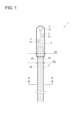
- FIG. 1 is a diagram for explaining an optical fiber cable according to the first embodiment.
- FIG. 2 is a cross-sectional view taken along line II-II of FIG.
- FIG. 3 is a cross-sectional view of an optical fiber core wire.
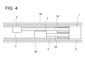
- FIG. 4 is a diagram for explaining a multicore connector for an optical fiber cable.
- FIG. 5 is a cross-sectional view of the cable main body of the optical fiber cable according to the second embodiment.
- FIG. 6 is a schematic diagram illustrating an optical fiber cable connection system.
- Optical fiber cables such as ultra-multi-core cables were laid by pulling and then connected to indoor cables by fusion splicing after laying. In the installation by pulling and the fusion splicing, it takes a long time to wind the optical fiber cable in a figure of eight, and the splicing work takes a long time. In order to shorten the installation time, it is conceivable to lay the cables by pneumatic feeding.
- An object of the present disclosure is to provide a multi-core optical fiber cable with improved workability.
- a fiber optic cable includes: (1) a plurality of optical fibers each having a core portion, a clad portion covering the outer periphery of the core portion, and a covering portion covering the outer periphery of the clad portion; a cable jacket housing the plurality of optical fiber core wires; An optical fiber cable comprising One end of the plurality of optical fiber core wires is provided with a multi-core connector in which the plurality of optical fiber core wires connected to one connector is 24 or more cores, The density of the plurality of optical fiber core wires in the optical fiber cable is 6.5 cores/mm 2 or more and 9.0 cores/mm 2 or less.
- the optical fiber cable is provided with optical fiber core wires at a high density as described above, the diameter of the optical fiber cable can be reduced. As a result, the weight of the optical fiber cable can be reduced, making it easier to lay the cable by pneumatic feeding. In addition, since the connector is provided in advance, fusion splicing work is not required, and connection work time can be shortened.
- the plurality of optical fibers of 1728 cores or more may be accommodated inside the cable jacket.
- an optical fiber cable containing 1728 or more optical fibers, that is, a so-called super-multi-fiber cable can be laid by pneumatic feeding.
- the outer diameter of the plurality of optical fibers may be less than 200 ⁇ m. According to the above configuration, the diameter of the optical fiber cable can be easily reduced by setting the outer diameter of the optical fiber cable to less than 200 ⁇ m.
- a fluctuation width of the outer diameter of the clad portion may be ⁇ 0.5 ⁇ m or less. According to the optical fiber cable having the above configuration, the fluctuation width of the outer diameter of the cladding portion is manufactured so as to be within a certain range. can.
- Silicone may be added to the cable jacket. According to the optical fiber cable having the above structure, the addition of silicone to the cable jacket reduces the coefficient of friction of the cable jacket with respect to the air-feeding duct. As a result, it is possible to realize an optical fiber cable with a long distance that can be pneumatically fed at the time of laying.
- the plurality of optical fibers are bundled into a plurality of subunits;
- the outer peripheries of the plurality of subunits may be coated with a subunit coating containing a flame retardant material.
- the plurality of subunit coating portions formed inside the optical fiber cable each contain a flame-retardant material.
- a coating thickness of the subunit coating portion may be 0.05 mm or more and 0.5 mm or less. If the coating thickness of the subunit coating is too thin, it will not be possible to effectively protect the optical fiber core inside. However, if the coating thickness of the subunit coating portion is as described above, it is possible to both protect the optical fiber core wire and reduce the diameter of the entire optical fiber cable.
- the coated portion of the plurality of optical fibers forming the subunit may contain a flame retardant material.
- the coating of the optical fiber core wire inside the subunit coating also contains a flame-retardant material, so that the flame resistance of the entire optical fiber cable is improved.
- a protection tube that accommodates the multi-core connector is provided at the tip of the optical fiber cable;
- the outer diameter of the protective tube may be equal to or less than the outer diameter of the optical fiber cable excluding the protective tube plus 2 mm. According to the optical fiber cable having the above configuration, even when the protection tube is provided at the tip of the multi-fiber connector, the diameter of the entire optical fiber cable can be sufficiently reduced.
- the number of cores of the plurality of optical fibers connectable with the multi-core connector may be 96 or more. According to the optical fiber cable having the above configuration, the number of required multi-core connectors is reduced by increasing the number of optical fiber core wires that can be connected by the multi-core connector, so that the diameter of the entire optical fiber cable can be reduced. achieved.
- a fiber optic cable connection system includes: (11) An optical fiber for connecting the optical fiber cable according to any one of (1) to (10) above to an indoor optical fiber cable having a multi-core connector with 24 or more cores at one end.
- a cable connection system, A connecting portion between the optical fiber cable and the indoor optical fiber cable is covered with a connection box.
- the multi-core connector can easily connect the optical fiber cable brought in from the outdoors and the indoor optical fiber cable.
- the connection portion is covered with the connection box, it is easy to effectively protect the connection portion.
- FIG. 1 is a diagram illustrating an optical fiber cable 1 according to the first embodiment.
- FIG. 2 is a cross-sectional view taken along line II-II of FIG.
- an optical fiber cable 1 has a cable main body 2 and a multicore connector 3 .
- the optical fiber cable 1 according to this embodiment is an optical fiber cable laid by pneumatic feeding.
- the multi-core connector 3 is, for example, a connector having an MT connector as a base structure. In FIG. 1, only three multi-core connectors 3 are shown for convenience of illustration, but the number of multi-core connectors 3 can be determined according to the number of optical fiber core wires 25 accommodated in the optical fiber cable 1. may be determined.
- the multi-core connector 3 is configured such that at least 24 or more optical fibers 25 can be connected to one multi-core connector 3 .
- the multi-core connector 3 has, for example, a plurality of ferrules 31 inside.
- the ferrule 31 is, for example, an MT ferrule in which the tips of the optical fibers 25 of a plurality of cores are inserted and fixed.
- the cable main body 2 has a slot rod 21, a pressure winding tape 22, a cable jacket 23, and a tensile strength member 24.
- the slot rod 21 has a plurality of slot grooves.
- the slot groove is provided in a spiral or SZ-like twisted shape in the longitudinal direction of the cable main body 2 .
- Each slot groove accommodates a plurality of optical fiber core wires 25 that are rolled from a parallel state and brought into a dense state.
- the optical fiber core wire 25 may be accommodated in the slot groove as an optical fiber tape core wire configured by connecting a plurality of optical fiber core wires 25 in parallel in a direction orthogonal to the longitudinal direction.
- a pressing tape 22 is wound around the slot rod 21 .
- the pressing tape 22 is wound longitudinally or helically around the entire slot rod 21 and optical fiber core wire 25 .
- the pressure winding tape 22 is made water-absorbent by adhering water-absorbent powder to a base fabric made of polyester or the like.
- the cable main body 2 according to the present embodiment includes the pressing tape 22 , the cable main body 2 does not necessarily have to include the pressing tape 22 .
- the cable jacket 23 covers the circumference of the pressing tape 22 .
- the pressure winding tape 22 and the optical fiber core wire 25 are accommodated in the space inside the cable jacket 23 .
- the thickness of the cable jacket 23 is preferably 1.5 mm.
- the space inside the cable jacket 23 accommodates the optical fiber core 25 .
- the density of the optical fibers 25 to be accommodated is 6.5 cores/mm 2 or more and 9.0 cores/mm 2 or less.
- the density of the optical fiber core wires 25 is 6.5 cores/mm 2 or more, the ratio of the area occupied by the optical fiber core wires 25 in the optical fiber cable 1 increases.
- the density of the optical fiber cores 25 is a value obtained by dividing the number of cores of the optical fiber cores 25 accommodated in the optical fiber cable 1 by the cable cross-sectional area (cross-sectional area obtained from the diameter of the cable body 2). be.
- the optical fiber core wires 25 with the same number of cores are accommodated, the optical fiber core wires 25 with 6.5 cores/mm 2 or more have a higher can be accommodated in a smaller space.
- the diameter of the optical fiber cable 1 can be reduced.
- the volume of the slot rod 21 and the cable jacket 23 provided around the slot rod 21 can be reduced, so that the weight of the entire optical fiber cable 1 can be reduced.
- the transmission loss of the entire optical fiber cable 1 may increase. /mm 2 or less.
- the optical fiber cable 1 can be made thinner and lighter. This facilitates laying by pneumatic feeding.
- the connectors are provided in advance, no fusion splicing work is required when connecting the optical fiber cables 1 to each other, thus shortening the time required for the connecting work.
- the number of optical fibers 25 housed inside the cable sheath 23 may be 1728 or more.
- the optical fiber cable 1 according to the present embodiment even in a so-called super-multi-fiber cable having a large number of optical fiber core wires 25 inside, it is possible to lay the cables by pneumatic feeding by configuring as described above. becomes.
- FIG. 3 is a cross-sectional view of the optical fiber cable 25.
- the optical fiber core wire 25 includes a glass fiber 253 composed of a core portion 251 having a higher refractive index than the surrounding glass and a clad portion 252 surrounding the core portion 251, and It has two layers of covering portions 254 and 255 and a colored layer 256 covering the circumference of the covering portion 255 .
- the inner covering portion 254 of the two layers of covering portions 254 and 255 is formed of a hardened primary resin.
- the outer coating portion 255 of the two layers of coating portions 254 and 255 is formed of a hardened secondary resin.
- the glass fiber 253 is provided with a core portion 251 at its central portion, and a clad portion 252 is provided so as to cover the periphery of the core portion 251 .
- a soft resin with a relatively low Young's modulus is used as a buffer layer for the primary resin that constitutes the inner primary coating portion that contacts the glass fiber 253 .
- a hard resin having a Young's modulus higher than that of the primary resin is used as a protective layer for the secondary resin forming the outer secondary coating portion.
- the Young's modulus of the cured product of the primary resin is 1.0 MPa or less, preferably 0.7 MPa or less at room temperature (eg, 23° C.).
- the cured product of the secondary resin has a Young's modulus of 900 MPa or higher, preferably 1000 MPa or higher, and more preferably 1500 MPa or higher at room temperature (for example, 23° C.).
- the diameter D1 of the optical fiber core wire 25 is less than 200 ⁇ m.
- the variation width of the outer diameter D2 of the clad portion 252 is manufactured within a certain range. Specifically, it is desirable that the variation width of the outer diameter D2 of the cladding portion 252 is ⁇ 0.5 ⁇ m or less.
- the fluctuation width of the outer diameter D2 of the cladding portion 252 is manufactured so as to fall within a certain range. It is possible to reduce the transmission loss that occurs during transmission.
- silicone may be added to the cable jacket 23 .
- the coefficient of friction of the cable jacket 23 with respect to the duct for air supply is lowered.
- the frictional force generated when the cable jacket 23 and the air supply duct 50 (see FIG. 4) rub against each other is reduced, so that the optical fiber cable 1 can be provided with a long distance for air supply during installation.
- the number of cores of the optical fiber core wires 25 that can be connected to the multi-core connector 3 is 96 cores or more. As the number of cores of the optical fiber core wires 25 to which the multi-core connector 3 can be connected increases, the number of the required multi-core connectors 3 decreases, so that the optical fiber cable 1 can be easily connected.
- the optical fiber cable 1 further has a protective tube 4 .
- the protective tube 4 is, for example, a member made of metal.
- the protective tube 4 is provided at the end of the optical fiber cable 1 and accommodates the multicore connector 3 therein.
- the protective tube 4 protects the ends of the cable body 2 and the multi-core connector 3 from being damaged during air feeding.
- the outer diameter D3 of the protective tube 4 is slightly larger than the outer diameter of the optical fiber cable 1 excluding the protective tube 4.
- the outer diameter of the optical fiber cable 1 excluding the protective tube 4" corresponds to the outer diameter D4 of the cable body 2.
- the outer diameter D3 of the protective tube 4 is preferably larger than the outer diameter D4 of the cable body 2 and smaller than the outer diameter D4+2 mm.
- the size of the outer diameter D3 of the protective tube 4 is suppressed within a certain range larger than the outer diameter of the optical fiber cable 1 excluding the protective tube 4. .
- the protective tube 4 is provided for protecting the multi-fiber connector 3 and the like, the diameter of the entire optical fiber cable 1 can be sufficiently reduced.
- FIG. 4 is a diagram for explaining the multicore connector 3 of the optical fiber cable 1.
- FIG. A case where a protective tube 4 is provided at the tip of the optical fiber cable 1 will be described with reference to FIG.
- the optical fiber cable 1 is inserted through the air supply duct 50 during installation.
- the inner diameter of the air supply duct 50 is, for example, 28 mm.
- the outer diameter of the cable body 2 is smaller than the outer diameter of the protective tube 4 by about 1 mm.
- the outer diameter of the cable body 2 is 22 mm, and the outer diameter of the protective tube 4 is 23 mm.
- a multi-core connector 3 is provided inside the protective tube 4 .
- a plurality of optical fibers are connected to the multi-core connector 3 .
- the multi-core connector 3 preferably has an outer diameter approximately half the inner diameter of the protective tube 4 .
- the inner diameter of the protective tube 4 is 19 mm, and the outer diameter of the multi-core connector is 10 mm.
- the multiple multi-core connectors 3 are arranged in the longitudinal direction of the optical fiber cable 1 as shown in FIG. Since the protective tube 4 can be displaced and arranged, it is possible to suppress the enlargement of the inner diameter of the protective tube 4 .
- FIG. 5 is a cross-sectional view of the cable body portion 2A of the optical fiber cable 1A according to the second embodiment.
- An optical fiber cable 1A according to the second embodiment includes a cable main body 2A and a multicore connector 3 (see FIGS. 1 and 4) common to the first embodiment, as in the first embodiment.
- the internal structure of the cable body 2A is different. More specifically, the slot rod 21 is not provided in the space inside the cable jacket, and the plurality of optical fibers 25 are bundled into each of the plurality of subunits 250 .
- Each subunit 250 is covered with a subunit covering portion 250a. By tearing the cable jacket 23, wiring can be performed for each subunit 250 covered by the subunit covering portion 250a.
- the subunit covering portion 250a is formed containing a flame retardant material.
- An example of the subunit covering portion 250a formed containing a flame-retardant material is, for example, covering the subunit 250 with flame-retardant polyolefin.
- optical fiber cables used indoors are required to have higher flame retardancy than optical fiber cables used outdoors. For this reason, optical fiber cables with different flame retardancy are used for indoor and outdoor use. Normally, when an outdoor optical fiber cable with low flame resistance is brought indoors, it is necessary to connect it with an indoor cable with high flame resistance before entering the building.
- the optical fiber cable 1A according to the present embodiment is configured such that a plurality of subunit covering portions 250a formed therein each contain a flame-retardant material. As a result, for example, even for wiring inside a building that requires higher flame resistance, it is possible to take out the optical fiber core 25 from the outdoor cable for each subunit 250 and lay it on each floor. Become. In this way, the handling of the optical fiber cable 1A is facilitated when it is laid.
- the coating thickness of the subunit coating portion 250a is preferably 0.05 mm or more and 0.5 mm or less. If the coating thickness of the subunit coating portion 250a is too thin, it will not be possible to effectively protect the optical fiber core wire inside. Thinning is not achieved. With the coating thickness of the subunit coating portion 250a as described above, it is possible to both protect the optical fiber cable 25 and reduce the diameter of the entire optical fiber cable 1A.
- the coating portions 254 and 255 of the plurality of optical fiber core wires 25 constituting the subunit 250 contain a flame-retardant material. Since not only the subunit coating portion 250a but also the coating portions 254 and 255 of the optical fiber core wire 25 therein contain a flame retardant material, the flame resistance of the entire optical fiber cable 1A is improved.
- FIG. 6 is a schematic diagram illustrating the optical fiber cable connection system 100.
- the optical fiber cable connection system 100 includes the optical fiber cable 1 according to the first embodiment that is pulled into the building H from outside the building H, and an indoor optical fiber cable 101. .
- the indoor optical fiber cable 101 has a multicore connector (not shown) with 24 or more cores at least at one end.
- the optical fiber cable 1 and the indoor optical fiber cable 101 can be connected by the multi-core connector 3 of the optical fiber cable 1 and the multi-core connector of the indoor optical fiber cable 101 .
- the optical fiber cable drawn into the building H from outside the building H may be the optical fiber cable 1A according to the second embodiment.
- the subunit 250 may be wired as the indoor optical fiber cable 101 without using the junction box 102 .
- the optical fiber cable 1 and the indoor optical fiber cable 101 are connected inside the junction box 102 .
- the joint between the optical fiber cable 1 and the indoor optical fiber cable 101 is covered with the joint box 102 .
- the optical fiber cable 1 Since the optical fiber cable 1 has the multicore connector 3, it can be easily connected to the indoor optical fiber cable 101. Moreover, since the connecting portion is covered with the connection box 102, it is easy to effectively protect the connecting portion.
Landscapes
- Physics & Mathematics (AREA)
- General Physics & Mathematics (AREA)
- Optics & Photonics (AREA)
- Mechanical Coupling Of Light Guides (AREA)
- Light Guides In General And Applications Therefor (AREA)
Priority Applications (3)
| Application Number | Priority Date | Filing Date | Title |
|---|---|---|---|
| JP2023565837A JP7743874B2 (ja) | 2021-12-10 | 2021-12-10 | 光ファイバケーブルおよび光ファイバケーブル接続システム |
| PCT/JP2021/045513 WO2023105748A1 (ja) | 2021-12-10 | 2021-12-10 | 光ファイバケーブルおよび光ファイバケーブル接続システム |
| US18/716,605 US20250044539A1 (en) | 2021-12-10 | 2021-12-10 | Optical fiber cable and optical fiber cable connection system |
Applications Claiming Priority (1)
| Application Number | Priority Date | Filing Date | Title |
|---|---|---|---|
| PCT/JP2021/045513 WO2023105748A1 (ja) | 2021-12-10 | 2021-12-10 | 光ファイバケーブルおよび光ファイバケーブル接続システム |
Publications (1)
| Publication Number | Publication Date |
|---|---|
| WO2023105748A1 true WO2023105748A1 (ja) | 2023-06-15 |
Family
ID=86729974
Family Applications (1)
| Application Number | Title | Priority Date | Filing Date |
|---|---|---|---|
| PCT/JP2021/045513 Ceased WO2023105748A1 (ja) | 2021-12-10 | 2021-12-10 | 光ファイバケーブルおよび光ファイバケーブル接続システム |
Country Status (3)
| Country | Link |
|---|---|
| US (1) | US20250044539A1 (https=) |
| JP (1) | JP7743874B2 (https=) |
| WO (1) | WO2023105748A1 (https=) |
Citations (9)
| Publication number | Priority date | Publication date | Assignee | Title |
|---|---|---|---|---|
| JPS63182611A (ja) * | 1987-01-23 | 1988-07-27 | Fujikura Ltd | コネクタの保持部 |
| JPH1048491A (ja) * | 1996-07-29 | 1998-02-20 | Sumitomo Electric Ind Ltd | コネクタ付光ケーブルの端末構造 |
| US20080175548A1 (en) * | 2007-01-23 | 2008-07-24 | Dennis Michael Knecht | Preconnectorized fiber optic cable assembly |
| US20150078709A1 (en) * | 2011-12-19 | 2015-03-19 | Corning Optical Communications LLC | Methods of reducing and/or avoiding fiber ordering in a connectorized multi-fiber, fiber optic cable system, and related fiber optic cables and assemblies |
| US20160041354A1 (en) * | 2014-08-08 | 2016-02-11 | Corning Optical Communications LLC | Optical fiber cable |
| WO2019142841A1 (ja) * | 2018-01-18 | 2019-07-25 | 住友電気工業株式会社 | 光ファイバケーブル |
| JP2020076957A (ja) * | 2018-10-01 | 2020-05-21 | オーエフエス ファイテル,エルエルシー | 間欠接着型光ファイバーリボンを収容する光ファイバーケーブルアセンブリのための多心コネクタ化 |
| CN211086722U (zh) * | 2019-12-31 | 2020-07-24 | 江苏中天科技股份有限公司 | 气吹微缆 |
| JP2020204752A (ja) * | 2019-06-19 | 2020-12-24 | 住友電気工業株式会社 | 光ファイバケーブル |
-
2021
- 2021-12-10 JP JP2023565837A patent/JP7743874B2/ja active Active
- 2021-12-10 WO PCT/JP2021/045513 patent/WO2023105748A1/ja not_active Ceased
- 2021-12-10 US US18/716,605 patent/US20250044539A1/en active Pending
Patent Citations (9)
| Publication number | Priority date | Publication date | Assignee | Title |
|---|---|---|---|---|
| JPS63182611A (ja) * | 1987-01-23 | 1988-07-27 | Fujikura Ltd | コネクタの保持部 |
| JPH1048491A (ja) * | 1996-07-29 | 1998-02-20 | Sumitomo Electric Ind Ltd | コネクタ付光ケーブルの端末構造 |
| US20080175548A1 (en) * | 2007-01-23 | 2008-07-24 | Dennis Michael Knecht | Preconnectorized fiber optic cable assembly |
| US20150078709A1 (en) * | 2011-12-19 | 2015-03-19 | Corning Optical Communications LLC | Methods of reducing and/or avoiding fiber ordering in a connectorized multi-fiber, fiber optic cable system, and related fiber optic cables and assemblies |
| US20160041354A1 (en) * | 2014-08-08 | 2016-02-11 | Corning Optical Communications LLC | Optical fiber cable |
| WO2019142841A1 (ja) * | 2018-01-18 | 2019-07-25 | 住友電気工業株式会社 | 光ファイバケーブル |
| JP2020076957A (ja) * | 2018-10-01 | 2020-05-21 | オーエフエス ファイテル,エルエルシー | 間欠接着型光ファイバーリボンを収容する光ファイバーケーブルアセンブリのための多心コネクタ化 |
| JP2020204752A (ja) * | 2019-06-19 | 2020-12-24 | 住友電気工業株式会社 | 光ファイバケーブル |
| CN211086722U (zh) * | 2019-12-31 | 2020-07-24 | 江苏中天科技股份有限公司 | 气吹微缆 |
Also Published As
| Publication number | Publication date |
|---|---|
| JPWO2023105748A1 (https=) | 2023-06-15 |
| US20250044539A1 (en) | 2025-02-06 |
| JP7743874B2 (ja) | 2025-09-25 |
Similar Documents
| Publication | Publication Date | Title |
|---|---|---|
| US5627932A (en) | Reduced diameter indoor fiber optic cable | |
| US6839494B2 (en) | Dual stage fiber optic cable design | |
| CN102197327B (zh) | 光纤电缆子单元组件 | |
| JP7156181B2 (ja) | 光ファイバケーブル | |
| US6681071B2 (en) | Dry core indoor/outdoor fiber optic cable | |
| US8718426B2 (en) | Optical fiber cables | |
| US20090087154A1 (en) | Optical fiber cables | |
| CN112334809B (zh) | 光纤电缆 | |
| US10338332B2 (en) | Optical fiber bundle | |
| US20080285924A1 (en) | Optical fiber cables | |
| CN104160316A (zh) | 紧凑、低成本外部设施或室内/室外光缆 | |
| CN107003490A (zh) | 光纤缆线 | |
| JP2012083418A (ja) | 光ファイバコード | |
| JP2016148709A (ja) | 光ファイバユニットおよび光ケーブル | |
| CN207164316U (zh) | 一种不锈钢螺旋管柔性铠装光缆 | |
| JP7743874B2 (ja) | 光ファイバケーブルおよび光ファイバケーブル接続システム | |
| CN110268296A (zh) | 减小直径的加固光纤配电线缆 | |
| TWM594154U (zh) | 加強型光纖纜線 | |
| CN109541765B (zh) | 一种光纤及使用该光纤的光缆 | |
| WO2023136263A1 (ja) | 光ファイバケーブル | |
| KR101524415B1 (ko) | 비 타이트버퍼 인입 및 옥내 광케이블 | |
| TWM677435U (zh) | 光纖纜線 | |
| JP4047248B2 (ja) | 光ドロップケーブル | |
| WO2025057409A1 (ja) | 光ファイバケーブル | |
| JP3166245U (ja) | 光ファイバケーブル |
Legal Events
| Date | Code | Title | Description |
|---|---|---|---|
| 121 | Ep: the epo has been informed by wipo that ep was designated in this application |
Ref document number: 21967242 Country of ref document: EP Kind code of ref document: A1 |
|
| WWE | Wipo information: entry into national phase |
Ref document number: 18716605 Country of ref document: US Ref document number: 2023565837 Country of ref document: JP |
|
| NENP | Non-entry into the national phase |
Ref country code: DE |
|
| 122 | Ep: pct application non-entry in european phase |
Ref document number: 21967242 Country of ref document: EP Kind code of ref document: A1 |