WO2023100717A1 - モジュールシステム - Google Patents
モジュールシステム Download PDFInfo
- Publication number
- WO2023100717A1 WO2023100717A1 PCT/JP2022/043155 JP2022043155W WO2023100717A1 WO 2023100717 A1 WO2023100717 A1 WO 2023100717A1 JP 2022043155 W JP2022043155 W JP 2022043155W WO 2023100717 A1 WO2023100717 A1 WO 2023100717A1
- Authority
- WO
- WIPO (PCT)
- Prior art keywords
- module
- connecting member
- mounting surface
- guide device
- pin
- Prior art date
- Legal status (The legal status is an assumption and is not a legal conclusion. Google has not performed a legal analysis and makes no representation as to the accuracy of the status listed.)
- Ceased
Links
Images



Classifications
-
- H—ELECTRICITY
- H02—GENERATION; CONVERSION OR DISTRIBUTION OF ELECTRIC POWER
- H02K—DYNAMO-ELECTRIC MACHINES
- H02K41/00—Propulsion systems in which a rigid body is moved along a path due to dynamo-electric interaction between the body and a magnetic field travelling along the path
- H02K41/02—Linear motors; Sectional motors
-
- H—ELECTRICITY
- H02—GENERATION; CONVERSION OR DISTRIBUTION OF ELECTRIC POWER
- H02K—DYNAMO-ELECTRIC MACHINES
- H02K41/00—Propulsion systems in which a rigid body is moved along a path due to dynamo-electric interaction between the body and a magnetic field travelling along the path
- H02K41/02—Linear motors; Sectional motors
- H02K41/035—DC motors; Unipolar motors
- H02K41/0352—Unipolar motors
- H02K41/0354—Lorentz force motors, e.g. voice coil motors
- H02K41/0358—Lorentz force motors, e.g. voice coil motors moving along a curvilinear path
-
- H—ELECTRICITY
- H02—GENERATION; CONVERSION OR DISTRIBUTION OF ELECTRIC POWER
- H02K—DYNAMO-ELECTRIC MACHINES
- H02K1/00—Details of the magnetic circuit
- H02K1/06—Details of the magnetic circuit characterised by the shape, form or construction
- H02K1/12—Stationary parts of the magnetic circuit
- H02K1/18—Means for mounting or fastening magnetic stationary parts on to, or to, the stator structures
-
- H—ELECTRICITY
- H02—GENERATION; CONVERSION OR DISTRIBUTION OF ELECTRIC POWER
- H02K—DYNAMO-ELECTRIC MACHINES
- H02K15/00—Processes or apparatus specially adapted for manufacturing, assembling, maintaining or repairing of dynamo-electric machines
- H02K15/14—Casings; Enclosures; Supports
-
- B—PERFORMING OPERATIONS; TRANSPORTING
- B65—CONVEYING; PACKING; STORING; HANDLING THIN OR FILAMENTARY MATERIAL
- B65G—TRANSPORT OR STORAGE DEVICES, e.g. CONVEYORS FOR LOADING OR TIPPING, SHOP CONVEYOR SYSTEMS OR PNEUMATIC TUBE CONVEYORS
- B65G54/00—Non-mechanical conveyors not otherwise provided for
- B65G54/02—Non-mechanical conveyors not otherwise provided for electrostatic, electric, or magnetic
-
- H—ELECTRICITY
- H02—GENERATION; CONVERSION OR DISTRIBUTION OF ELECTRIC POWER
- H02K—DYNAMO-ELECTRIC MACHINES
- H02K2213/00—Specific aspects, not otherwise provided for and not covered by codes H02K2201/00 - H02K2211/00
- H02K2213/12—Machines characterised by the modularity of some components
Definitions
- the present invention relates to a module system configured by connecting modules in which guide devices are installed.
- a configuration has been proposed in which a projection is provided on one of the mutually connected stator blocks and a recess is provided on the other, and the projection and the recess are fitted to connect the stator blocks (for example, See Patent Document 1.)
- a module system configured by connecting modules with built-in guide devices is conceivable.
- the present invention has been made in view of the above circumstances, and an object of the present invention is to provide a technique that facilitates positioning when connecting modules each incorporating a guide device. .
- a module system configured by positioning a first module incorporating a first guide device and a second module incorporating a second guide device along a guiding direction, The first module is arranged such that the gap between the end of the first guide device on the side of the second module and the end of the second guide device on the side of the first module is a predetermined distance. and a first positioning part for positioning the second module; The first module and the a second positioning part for positioning with the second module; Prepare.
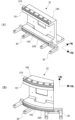
- FIG. 2A is a perspective view of a module in which a straight track rail is incorporated
- FIG. 2B is a perspective view of a module in which a curved track rail is incorporated. It is a side view of the module seen from the X-axis direction. It is an expansion perspective view of an attachment surface.
- 5A is a first perspective view of the connecting member
- FIG. 5B is a second perspective view of the connecting member viewed from a direction different from the first perspective view.
- FIG. 10 is a diagram for explaining a method of attaching a connecting member when connecting the first module and the second module
- FIG. 5 is a diagram showing the relative positions of the first track rail and the second track rail when the first module and the second module are connected by the connecting member; It is a figure which shows the structure of the connection member in a modification.
- a module system which is one aspect of the present invention, comprises a first module incorporating a first guiding device and a second module incorporating a second guiding device along a guiding direction. It is configured by being connected to each other. The first module and the second module are positioned and connected along the guiding direction.
- the number of modules constituting the module system according to the present invention is not limited to two.
- the plurality of first modules may have guiding devices of the same shape, or may have guiding devices of different shapes.
- the plurality of second modules may have guides of the same shape, or may have guides of different shapes.
- Modules can also be combined to form an infinite circulation type module system.
- a module system comprises a first positioning part and a second positioning part.
- the first positioning portion is configured to provide a predetermined distance between an end portion of the first guide device on the second module side and an end portion of the second guide device on the first module side. and a second module.
- the second positioning part is arranged such that the deviation between the axial direction of the first guide device and the axial direction of the second guide device in a direction orthogonal to the guiding direction in plan view is equal to or less than a predetermined deviation amount. It is configured to position the first module and the second module.
- the guide direction and the axial direction of the guide device refer to the end portion of the guide device. are the guiding direction and the axial direction in .
- the end portion of the first guide device on the side of the second module and the first portion of the second guide device are positioned by the first positioning part so that the gap between the module-side end is a predetermined distance.
- the second positioning portion is arranged so that the deviation between the axial direction of the first guide device and the axial direction of the second guide device in a direction orthogonal to the guiding direction in plan view is equal to or less than a predetermined deviation amount. Positioning of one module and a second module is also done. As a result, it is possible to easily perform positioning when connecting the first module and the second module. That is, even those who do not have special skills can assemble the module system.
- the first positioning portion may be configured including a first pin, a second pin, and a first connecting member.
- the first pin may be provided on the first module and configured to protrude in a direction orthogonal to the guiding direction in plan view.
- the second pin may be provided on the second module and configured to protrude in a direction orthogonal to the guiding direction in plan view.
- the first connecting member has a first fitting hole and a second fitting hole aligned in the guiding direction, the first fitting hole is fitted with the first pin, and the second fitting hole is fitted with the first pin. It may be configured to be fixed to the first module and the second module in a state in which the second pin is fitted to the module.
- the fixing of the first connecting member to the first module and the fixing of the first connecting member to the second module may be fixed by fastening bolts or the like, for example.
- the first positioning portion includes the first pin, the second pin, and the first connecting member
- an operator who assembles the module system may place the first connecting member in the first fitting position.
- a first pin is fitted into the hole and a second pin is fitted into the second fitting hole to fix the module to the first module and the second module.
- At least one of the first fitting hole and the second fitting hole in the first positioning portion has a length in the guiding direction larger than the diameters of the first pin and the second pin. good too.
- the gap between the modules in the guiding direction (the guiding The gap between the ends of the device) can be easily fine-tuned. As a result, it is possible to prevent the gap between some modules from becoming too wide or the gap between some modules from becoming too narrow.
- the second positioning portion may be configured including a first mounting surface, a second mounting surface, and a second connecting member.
- the first mounting surface may be provided in the vicinity of the end on the second module side of the side surface of the first module, and may be formed by a vertical surface extending along the guiding direction.
- the second mounting surface may be provided in the vicinity of the end on the first module side of the side surface of the second module and formed of a vertical surface extending along the guiding direction.
- the second connecting member may be fixed to the first mounting surface and the second mounting surface so that the first mounting surface and the second mounting surface are flush with each other. Fixation of the second connecting member to the first mounting surface of the first module and fixing of the second connecting member to the second mounting surface of the second module are performed by fastening bolts or the like, for example. You may do so.
- the second positioning portion includes the first mounting surface, the second mounting surface, and the second connecting member
- an operator who assembles the module system may move the second connecting member to the second mounting surface.
- An operation of fixing to the first mounting surface of one module and the second mounting surface of the second module may be performed.
- the axial direction of the first guide device in the direction orthogonal to the guiding direction in plan view and the second mounting surface are aligned.
- the first module and the second module are positioned such that the deviation from the axial direction of the guide device is equal to or less than a predetermined deviation amount.
- first connecting member and the second connecting member may be configured integrally.
- first pin may be provided on the first mounting surface
- second pin may be provided on the second mounting surface.
- an operator who assembles the module system inserts the integrally configured first connecting member and second connecting member (hereinafter sometimes referred to as "connecting member") into the first fitting. With the first pin fitted in the mating hole and the second pin fitted in the second fitting hole, the operation of fixing to the first mounting surface and the second mounting surface may be performed. .
- the gap between the end portion of the first guide device on the side of the second module and the end portion of the second guide device on the side of the first module becomes a predetermined distance, and is perpendicular to the guide direction in plan view.
- the first module and the second module are positioned such that the deviation between the axial direction of the first guide device and the axial direction of the second guide device in the direction of .
- FIG. 1 is a diagram showing an example of a module system 1 according to this embodiment.
- the module system 1 is configured by connecting a plurality of modules 10 via connecting members 30 .
- the plurality of modules 10 are connected in an infinite circulation pattern, but they may be connected in a finite stroke pattern.
- FIG. 2 is a perspective view showing a schematic configuration of the module 10. As shown in FIG. 3 is a side view of module 10. FIG. 4 is an enlarged perspective view of the mounting surface 103 of the module 10. FIG. 2A is a perspective view of the module 10 in which the linear track rail is incorporated, and FIG. 2B is a perspective view of the module 10 in which the curved track rail is incorporated.
- the guiding direction of the track rail is defined as the X-axis direction
- the direction orthogonal to the X-axis direction in plan view is defined as the Y-axis direction.
- the guiding direction at the end of the track rail is defined as the X-axis direction.
- the XY axis direction at one end of the track rail may be different from the XY axis direction at the other end of the track rail, as shown in FIG. In the example, only the XY axis direction corresponding to one end (the right end in FIG. 2B) is shown for convenience.
- the module 10 includes a substantially L-shaped base 100 when viewed from the side.
- a pair of plate-shaped support portions 101 and 102 are horizontally projected from the front side of the base 100 (for example, the right side in FIG. 3).
- a pair of track rails 210-220 are attached to the pair of support portions 101-102, respectively.
- a track rail 210 is attached to the upper surface of the upper support portion 101 of the pair of support portions 101 and 102
- a track rail 220 is attached to the lower surface of the lower support portion 102. be done.
- the pair of track rails 210-220 are configured to guide a moving member such as a carriage along the longitudinal direction of the track rails 210-220.
- the moving member is, for example, a pair of track rails 210-220 via a large number of rolling elements (balls, rollers, etc.) that roll in rolling grooves and circulate in circulation paths in the moving members. 220.
- the base 100 is assembled with a drive mechanism 230 for moving the moving members along the track rails 210-220.
- the drive mechanism 230 includes, for example, a linear motor and an amplifier.
- the linear motor may be, for example, a moving coil type motor. Note that the linear motors may be incorporated into the track rails 210-220.
- the track rails 210-220 in this embodiment correspond to the guide device according to the present invention.
- a mounting surface 103 is formed.
- the mounting surface 103 is formed by a vertical surface extending in the X-axis direction.
- the mounting surface 103 is provided with a pin 104 extending in the Y-axis direction.
- the mounting surface 103 is also provided with a plurality of female screw holes 105 . Although two female screw holes 105 are provided in the example shown in FIG. Such mounting surfaces 103 are provided near both ends of each module 10 .
- Each module 10 according to the present embodiment is configured such that when the mounting surface 103 of the module 10 and the mounting surface 103 of another module 10 are flush with each other, the axial direction of the ends of the track rails 210 to 220 of the module 10 is , and the axial direction of the ends of the track rails 210 to 220 of the other modules 10, and the deviation in the Y-axis direction is not more than a predetermined amount of deviation.
- the predetermined amount of deviation is the maximum amount of deviation that allows the moving member to transfer from one of the track rails 210A to 220A and the track rails 210B to 220B without any trouble, or the maximum amount of deviation minus a margin. This is the amount of deviation.
- FIG. 5A is a first perspective view of the connecting member 30.
- FIG. 5B is a second perspective view of the connecting member 30 viewed from a direction different from that of the first perspective view.
- the connecting member 30 is a member that positions and connects the two modules 10 along the guide direction (X-axis direction).
- the connecting member 30 in this embodiment also functions as a leg for stabilizing the posture of the module 10 .
- the connecting member 30 includes a back plate portion 310 and a pair of legs 320 to 330, as shown in FIGS. 5A and 5B.
- the back plate portion 310 is formed in a plate shape extending in the vertical direction.
- a pair of legs 320 to 330 are provided to horizontally protrude from the front surface 370 of the back plate portion 310 .
- the back plate portion 310 and the pair of leg portions 320-330 are integrally formed so that the bottom surface of the back plate portion 310 and the bottom surfaces of the pair of leg portions 320-330 form a continuous surface along the horizontal direction. It is formed.
- the rear surface 380 of the back plate portion 310 is formed by a plane (vertical surface) perpendicular to the bottom surface of the back plate portion 310 and the bottom surfaces of the pair of legs 320-330. Further, the back plate portion 310 is provided with a plurality of through holes 340 and a pair of fitting holes 350-360.
- the plurality of through-holes 340 are holes for passing fastening bolts for fixing the connecting member 30 to the module 10 , and penetrate horizontally from the front surface 370 to the rear surface 380 .
- a pair of mating holes 350 - 360 are formed by blind holes extending horizontally from the back surface 380 . Note that the pair of fitting holes 350 to 360 may be formed so as to penetrate horizontally from the rear surface 380 to the front surface 370 .
- the pair of fitting holes 350 to 360 are formed so that their inner diameters are approximately the same as the outer diameters of the pins 104 of the module 10 .
- the distance between the pair of fitting holes 350 and 360 is such that the pins 104 of one module 10 of the two modules 10 connected by the connecting member 30 are fitted into the fitting holes 350 and the other module 10
- the gap between the end of the track rail 210-220 of one module 10 and the end of the track rail 210-220 of the other module 10 is a predetermined distance.
- the "predetermined distance” is, for example, a distance that can absorb the thermal expansion of the track rails 210-220, and the gap during contraction of the track rails 210-220 interferes with the movement of the moving member. It is determined to be a distance that does not cause Such a predetermined distance is determined in consideration of manufacturing tolerances of the module 10 and the like.
- FIG. 6 is a diagram for explaining a method of connecting the modules 10.
- one of the two modules 10 connected by the connecting member 30 is called the first module 10A, and the other is called the second module 10B.
- A shall be added to the end of the reference numerals for the constituent elements of the first module 10A.
- B shall be added to the end of the reference numerals for the components of the second module 10B.
- the pins 104A projecting from the mounting surface 103A of the first module 10A are fitted into the fitting holes 360 of the connecting member 30. and the pins 104B projecting from the mounting surface 103B of the second module 10B are positioned so that they can be fitted into the fitting holes 350 of the connecting member 30.
- Adjust the positions of 10A and the second module 10B That is, the positions of the first module 10A and the second module 10B are adjusted so that the positional relationship shown in FIG. 6 is obtained.
- the pins 104A of the first module 10A are fitted into the fitting holes 360, and the pins 104B of the second module 10B are fitted into the fitting holes 350.
- a connecting member 30 is attached to the first module 10A and the second module 10B so as to mate. With the connecting member 30 attached to the first module 10A and the second module 10B in this way, a plurality of fastening bolts are passed through the plurality of through holes 341 of the connecting member 30, respectively, to secure the first module 10A. It is screwed into the female screw hole 105 . By tightening each fastening bolt with a specified torque, the connecting member 30 is fixed to the first module 10A and the second module 10B.
- the mounting surface 103A of the first module 10A and the mounting surface 103B of the second module 10B are aligned with each other. the back surface 380 of the .
- the mounting surface 103A of the first module 10A and the mounting surface 103B of the second module 10B are flush with each other along the rear surface 380 of the connecting member 30. As shown in FIG.
- the track rails 210A to 220A and the axial direction of the ends of the track rails 210B-220B on the side of the first module 10A is less than a predetermined amount of deviation in the Y-axis direction.
- a first module 10A and a second module 10B are designed and manufactured.
- the mounting surface 103A of the first module 10A and the mounting surface 103B of the second module 10B are flush with each other.
- the first module 10A and the second module 10B are arranged so that the amount of deviation (D1 in FIG. 7) in the axial direction (L2 in FIG. 7) and the Y-axis direction (D1 in FIG. 7) of will be positioned.
- the distance between the pair of fitting holes 350 and 360 in the connecting member 30 is such that the pins 104A of the first module 10A are fitted into the fitting holes 360.
- the ends of the track rails 210A-220A on the side of the second module 10B and the first modules of the track rails 210B-220B The gap between the end on the 10A side is determined to be less than or equal to a predetermined distance.
- the pin 104A of the first module 10A fitted into the fitting hole 360 of the connecting member 30 and the pin 104B of the second module 10B fitted into the fitting hole 350 of the connecting member 30, when the first module 10A and the second module 10B are connected by the connecting member 30, as shown in FIG. -
- the first module 10A and the second module 10B are positioned such that the gap (G1 in FIG. 7) between the end of the 220B on the first module 10A side is less than or equal to a predetermined distance. It will be.
- the connecting member 300 when the modules 10 are connected to each other using the connecting member 300, the relative positions of the track rails 210-220 between the modules 10 can be positioned at appropriate positions. As a result, the operator who assembles the module system 1 can position the modules 10 only by connecting the modules 10 using the connecting member 30 . Therefore, even a person who does not have special skills can easily perform positioning when connecting the modules 10 to each other.
- FIG. 8 is a view of the connecting member 30 in this modified example as seen from the rear side.
- a plurality of through holes 341 and a pair of fitting holes 351 to 361 are provided in the back plate portion 310 of the connecting member 30 in this modified example.
- the arrangement order of the plurality of through holes 341 and the pair of fitting holes 351 to 361 is the same as in the above-described embodiment.
- the pair of fitting holes 351-361 are elongated in the X-axis direction. That is, the pair of fitting holes 351 to 361 in this modified example are formed so that the length in the X-axis direction is larger than the diameter of the pin 104 .
- the inner diameter thereof may be larger than the outer diameter of the pin 104 .
- only one of the pair of fitting holes 351 to 361 may be elongated, or the inner diameter of either one may be larger than the outer diameter of the pin 104 .
- the shape and spacing of the pair of fitting holes 351 to 361 in this modified example are such that the connecting member 30 is positioned between the first module 10A and the second module 10B when the first module 10A and the second module 10B are spaced the farthest apart. 10B, the gaps between the ends of the track rails 210A-220A and the ends of the track rails 210B-220B are determined to be equal to or less than the predetermined distance described above.
- the plurality of through holes 340 are arranged such that the inner diameter of the plurality of through holes 341 is larger than the outer diameter of the threaded portion of the fastening bolt. shall be formed.
- the pins 104A of the first module 10A are fitted into the fitting holes 361, and the pins 104B of the second module 10B are fitted into the fitting holes. 351 and before the connecting member 30 is fixed to the first module 10A and the second module 10B with fastening bolts, the first module 10A and the second module 10B are connected. It is possible to finely adjust the relative position in the X-axis direction.
- the operator who assembles the module system 1 is in a state in which the pins 104 are fitted in the pair of fitting holes 351 to 361 of the connecting member 30, By temporarily assembling the module system 1 before the connecting members 30 are fixed with the fastening bolts, the gap between the modules 10 in the X-axis direction can be adjusted. As a result, when assembling the endless circulation type module system as shown in FIG. The gap between the modules 10 in the X-axis direction can be easily adjusted so that the gap is not too large.
- the connecting member has the function of the leg
- the connecting member may be configured so as not to have the function of the leg.
- the connecting member may be composed only of a back plate portion having a pair of fitting holes and a plurality of through holes.
- the mounting surface of the module is provided at a location other than the vicinity of the bottom as long as it is located near the end in the X-axis direction on one side surface of the module (the side surface on which the support portion is projected). good too.
- Reference Signs List 1 module system, 10: module, 10A: first module, 10B: second module, 100: base, 101-102: support, 103 (103A -103B) Mounting surface 104 (104A-104B) Pin 105
- Female screw hole 210-220 (210A-220A, 210B-220B) Track rail 230 Drive Mechanism 30 Connecting member 310 Back plate portion 320-330 Leg portion 340 Through hole 350-360 Fitting hole 351-361 Fitting hole
Landscapes
- Engineering & Computer Science (AREA)
- Power Engineering (AREA)
- Physics & Mathematics (AREA)
- Chemical & Material Sciences (AREA)
- Combustion & Propulsion (AREA)
- Electromagnetism (AREA)
- Manufacturing & Machinery (AREA)
- Insertion Pins And Rivets (AREA)
- Bearings For Parts Moving Linearly (AREA)
- Photovoltaic Devices (AREA)
Abstract
Description
第1の案内装置が組み込まれた第1のモジュールと第2の案内装置が組み込まれた第2のモジュールとを案内方向に沿って位置決めして構成される、モジュールシステムであって、
前記第1の案内装置における前記第2のモジュール側の端部と前記第2の案内装置における前記第1のモジュール側の端部との間隙が所定の距離になるように、前記第1のモジュールと前記第2のモジュールとの位置決めを行う第1の位置決め部と、
平面視で前記案内方向と直交する方向における前記第1の案内装置の軸方向と前記第2の案内装置の軸方向とのズレが所定のズレ量以下となるように、前記第1のモジュールと前記第2のモジュールとの位置決めを行う第2の位置決め部と、
を備える。
図1は、本実施形態におけるモジュールシステム1の一例を示す図である。モジュールシステム1は、複数のモジュール10を、連結部材30を介して連結して構成される。図1に示す例では、複数のモジュール10を、無限循環型に連結しているが、有限ストローク型に連結されてもよい。
モジュールシステム1に含まれるモジュール10の構成について、図2から図4に基づいて説明する。図2は、モジュール10の概略構成を示す斜視図である。図3は、モジュール10の側面図である。図4は、モジュール10の取付面103の拡大斜視図である。なお、図2中(A)は直線状の軌道レールが組み込まれたモジュール10の斜視図であり、図2中(B)は曲線状の軌道レールが組み込まれたモジュール10の斜視図である。
次に、本実施形態における連結部材30の構成について、図5に基づいて説明する。図5中(A)は、連結部材30の第1の斜視図である。図5中(B)は、第1の斜視図とは異なる方向から見た、連結部材30の第2の斜視図である。
次に、本実施形態におけるモジュールシステム1において、モジュール10を連結する方法を説明する。図6は、モジュール10を連結する方法を説明するための図である。ここでは、連結部材30によって連結される2つのモジュール10の一方を第1のモジュール10Aと称し、他方を第2のモジュール10Bと称するものとする。これに伴い、第1のモジュール10Aの構成要素については、符号の末尾に「A」を付加するものとする。同様に、第2のモジュール10Bの構成要素については、符号の末尾に「B」を付加するものとする。
前述した実施形態では、連結部材の嵌合孔の内径が、モジュールの取付面に設けられるピンの外径と略同じに形成される例について述べた。これに対し、本変形例では、嵌合孔の内径が、ピンの外径よりも大きく形成される例について述べる。
前述した実施形態及び変形例では、連結部材が脚部の機能を有する例について述べたが、脚部の機能を有さないように構成されてもよい。例えば、連結部材は、一対の嵌合孔と複数の通し孔とを有する背板部のみから構成されてもよい。その場合、モジュールの取付面は、モジュールの一方の側面(支持部が突設される側の側面)における、X軸方向の端部の近傍であれば、底部の近傍以外の場所に設けられてもよい。
Claims (5)
- 第1の案内装置が組み込まれた第1のモジュールと第2の案内装置が組み込まれた第2のモジュールとを案内方向に沿って位置決めして構成される、モジュールシステムであって、
前記第1の案内装置における前記第2のモジュール側の端部と前記第2の案内装置における前記第1のモジュール側の端部との間隙が所定の距離になるように、前記第1のモジュールと前記第2のモジュールとの位置決めを行う第1の位置決め部と、
平面視で前記案内方向と直交する方向における前記第1の案内装置の軸方向と前記第2の案内装置の軸方向とのズレが所定のズレ量以下となるように、前記第1のモジュールと前記第2のモジュールとの位置決めを行う第2の位置決め部と、
を備える、モジュールシステム。 - 前記第1の位置決め部は、
前記第1のモジュールに設けられ、平面視において前記案内方向と直交する方向に突出する第1のピンと、
前記第2のモジュールに設けられ、平面視において前記案内方向と直交する方向に突出する第2のピンと、
前記案内方向に並ぶ第1の嵌合孔と第2の嵌合孔とを有し、前記第1の嵌合孔に前記第1のピンと嵌合させ且つ前記第2の嵌合孔に前記第2のピンを嵌合させた状態で、前記第1のモジュール及び前記第2のモジュールに固定される第1の連結部材と、
を含む、
請求項1に記載のモジュールシステム。 - 前記第1の嵌合孔と前記第2の嵌合孔の少なくとも一方は、前記案内方向における長さが前記第1のピン及び前記第2のピンの径よりも大きく形成される、
請求項2に記載のモジュールシステム。 - 前記第2の位置決め部は、
前記第1のモジュールの側面における前記第2のモジュール側の端部の近傍に設けられ、前記案内方向に沿って延在する鉛直面で形成される第1の取付面と、
前記第2のモジュールの側面における前記第1のモジュール側の端部の近傍に設けられ、前記案内方向に沿って延在する鉛直面で形成される第2の取付面と、
前記第1の取付面と前記第2の取付面とが面一になるように、前記第1の取付面と前記第2の取付面とに固定される第2の連結部材と、
を含む、
請求項2又は3に記載のモジュールシステム。 - 前記第1のピンが前記第1の取付面に設けられ、
前記第2のピンが前記第2の取付面に設けられ、
前記第1の連結部材と前記第2の連結部材とが一体的に構成される、
請求項4に記載のモジュールシステム。
Priority Applications (5)
| Application Number | Priority Date | Filing Date | Title |
|---|---|---|---|
| JP2023564900A JPWO2023100717A1 (ja) | 2021-11-30 | 2022-11-22 | |
| KR1020247019108A KR20240112289A (ko) | 2021-11-30 | 2022-11-22 | 모듈 시스템 |
| CN202280077627.XA CN118302943A (zh) | 2021-11-30 | 2022-11-22 | 模块系统 |
| DE112022005720.3T DE112022005720T5 (de) | 2021-11-30 | 2022-11-22 | Modulsystem |
| US18/713,861 US20250038633A1 (en) | 2021-11-30 | 2022-11-22 | Module system |
Applications Claiming Priority (2)
| Application Number | Priority Date | Filing Date | Title |
|---|---|---|---|
| JP2021194434 | 2021-11-30 | ||
| JP2021-194434 | 2021-11-30 |
Publications (1)
| Publication Number | Publication Date |
|---|---|
| WO2023100717A1 true WO2023100717A1 (ja) | 2023-06-08 |
Family
ID=86612052
Family Applications (1)
| Application Number | Title | Priority Date | Filing Date |
|---|---|---|---|
| PCT/JP2022/043155 Ceased WO2023100717A1 (ja) | 2021-11-30 | 2022-11-22 | モジュールシステム |
Country Status (7)
| Country | Link |
|---|---|
| US (1) | US20250038633A1 (ja) |
| JP (1) | JPWO2023100717A1 (ja) |
| KR (1) | KR20240112289A (ja) |
| CN (1) | CN118302943A (ja) |
| DE (1) | DE112022005720T5 (ja) |
| TW (1) | TW202332844A (ja) |
| WO (1) | WO2023100717A1 (ja) |
Citations (2)
| Publication number | Priority date | Publication date | Assignee | Title |
|---|---|---|---|---|
| JPH05140903A (ja) * | 1991-11-21 | 1993-06-08 | Railway Technical Res Inst | 鉄道の分岐装置 |
| WO2018055708A1 (ja) * | 2016-09-21 | 2018-03-29 | ヤマハ発動機株式会社 | リニアコンベア装置 |
Family Cites Families (2)
| Publication number | Priority date | Publication date | Assignee | Title |
|---|---|---|---|---|
| JPH04210764A (ja) | 1990-12-14 | 1992-07-31 | Matsushita Electric Works Ltd | リニアモータの固定子ブロックの連結構造 |
| JP2000312463A (ja) * | 1999-04-27 | 2000-11-07 | Shinko Electric Co Ltd | リニアモータのレール接続構造 |
-
2022
- 2022-11-22 US US18/713,861 patent/US20250038633A1/en active Pending
- 2022-11-22 DE DE112022005720.3T patent/DE112022005720T5/de active Pending
- 2022-11-22 JP JP2023564900A patent/JPWO2023100717A1/ja active Pending
- 2022-11-22 WO PCT/JP2022/043155 patent/WO2023100717A1/ja not_active Ceased
- 2022-11-22 TW TW111144493A patent/TW202332844A/zh unknown
- 2022-11-22 CN CN202280077627.XA patent/CN118302943A/zh active Pending
- 2022-11-22 KR KR1020247019108A patent/KR20240112289A/ko active Pending
Patent Citations (2)
| Publication number | Priority date | Publication date | Assignee | Title |
|---|---|---|---|---|
| JPH05140903A (ja) * | 1991-11-21 | 1993-06-08 | Railway Technical Res Inst | 鉄道の分岐装置 |
| WO2018055708A1 (ja) * | 2016-09-21 | 2018-03-29 | ヤマハ発動機株式会社 | リニアコンベア装置 |
Also Published As
| Publication number | Publication date |
|---|---|
| KR20240112289A (ko) | 2024-07-18 |
| CN118302943A (zh) | 2024-07-05 |
| JPWO2023100717A1 (ja) | 2023-06-08 |
| US20250038633A1 (en) | 2025-01-30 |
| TW202332844A (zh) | 2023-08-16 |
| DE112022005720T5 (de) | 2024-09-19 |
Similar Documents
| Publication | Publication Date | Title |
|---|---|---|
| WO2018055709A1 (ja) | リニアコンベア装置 | |
| JP4571730B2 (ja) | 相対可動装置 | |
| JP3547209B2 (ja) | 直動転がり案内ユニット | |
| JP3488550B2 (ja) | エレベータガイドレールの接続装置 | |
| US11396429B2 (en) | Conveyance device, driven unit, auxiliary unit, and pallet | |
| WO2018055708A1 (ja) | リニアコンベア装置 | |
| JP4150411B2 (ja) | ステージ装置 | |
| CN111806993A (zh) | 用于连接输送机轨道的适配衔接连接器系统和方法 | |
| US20250038633A1 (en) | Module system | |
| CN114016388A (zh) | 悬索桥索鞍 | |
| US8628245B2 (en) | Connection structure of linear motor type transport device | |
| JP3055616B2 (ja) | コネクタ装置 | |
| WO2023157546A1 (ja) | レールの接続構造 | |
| CN219221684U (zh) | 地轨底座、底座组件和地轨 | |
| CN110719884B (zh) | 用于安装电梯系统的方法 | |
| TWI414902B (zh) | Liquid crystal exposure device | |
| WO2025199624A1 (en) | Modular track section for a linear motor conveyor system | |
| CN222978866U (zh) | 门架结构以及检测系统 | |
| JP7863175B2 (ja) | スライド部材および部品実装機 | |
| JP2008246653A (ja) | 石材連結構造及び石材連結方法 | |
| JP3721969B2 (ja) | ステージ装置 | |
| KR100539097B1 (ko) | 레이저 가공기의 테이블 | |
| RU2402698C2 (ru) | Соединительное устройство, деформируемое в одном направлении | |
| KR20250179390A (ko) | 모듈러 엘리베이터 제조방법 | |
| TWI902091B (zh) | 滑軌套件 |
Legal Events
| Date | Code | Title | Description |
|---|---|---|---|
| 121 | Ep: the epo has been informed by wipo that ep was designated in this application |
Ref document number: 22901150 Country of ref document: EP Kind code of ref document: A1 |
|
| WWE | Wipo information: entry into national phase |
Ref document number: 202280077627.X Country of ref document: CN |
|
| ENP | Entry into the national phase |
Ref document number: 2023564900 Country of ref document: JP Kind code of ref document: A |
|
| WWE | Wipo information: entry into national phase |
Ref document number: 18713861 Country of ref document: US |
|
| ENP | Entry into the national phase |
Ref document number: 20247019108 Country of ref document: KR Kind code of ref document: A |
|
| 122 | Ep: pct application non-entry in european phase |
Ref document number: 22901150 Country of ref document: EP Kind code of ref document: A1 |