WO2023100360A1 - 電力変換装置、モータ駆動装置および冷凍サイクル適用機器 - Google Patents
電力変換装置、モータ駆動装置および冷凍サイクル適用機器 Download PDFInfo
- Publication number
- WO2023100360A1 WO2023100360A1 PCT/JP2021/044502 JP2021044502W WO2023100360A1 WO 2023100360 A1 WO2023100360 A1 WO 2023100360A1 JP 2021044502 W JP2021044502 W JP 2021044502W WO 2023100360 A1 WO2023100360 A1 WO 2023100360A1
- Authority
- WO
- WIPO (PCT)
- Prior art keywords
- voltage
- frequency
- detection unit
- power converter
- ripple
- Prior art date
- Legal status (The legal status is an assumption and is not a legal conclusion. Google has not performed a legal analysis and makes no representation as to the accuracy of the status listed.)
- Ceased
Links
Images






Classifications
-
- H—ELECTRICITY
- H02—GENERATION; CONVERSION OR DISTRIBUTION OF ELECTRIC POWER
- H02P—CONTROL OR REGULATION OF ELECTRIC MOTORS, ELECTRIC GENERATORS OR DYNAMO-ELECTRIC CONVERTERS; CONTROLLING TRANSFORMERS, REACTORS OR CHOKE COILS
- H02P21/00—Arrangements or methods for the control of electric machines by vector control, e.g. by control of field orientation
- H02P21/05—Arrangements or methods for the control of electric machines by vector control, e.g. by control of field orientation specially adapted for damping motor oscillations, e.g. for reducing hunting
-
- F—MECHANICAL ENGINEERING; LIGHTING; HEATING; WEAPONS; BLASTING
- F25—REFRIGERATION OR COOLING; COMBINED HEATING AND REFRIGERATION SYSTEMS; HEAT PUMP SYSTEMS; MANUFACTURE OR STORAGE OF ICE; LIQUEFACTION SOLIDIFICATION OF GASES
- F25B—REFRIGERATION MACHINES, PLANTS OR SYSTEMS; COMBINED HEATING AND REFRIGERATION SYSTEMS; HEAT PUMP SYSTEMS
- F25B31/00—Compressor arrangements
- F25B31/02—Compressor arrangements of motor-compressor units
-
- H—ELECTRICITY
- H02—GENERATION; CONVERSION OR DISTRIBUTION OF ELECTRIC POWER
- H02P—CONTROL OR REGULATION OF ELECTRIC MOTORS, ELECTRIC GENERATORS OR DYNAMO-ELECTRIC CONVERTERS; CONTROLLING TRANSFORMERS, REACTORS OR CHOKE COILS
- H02P21/00—Arrangements or methods for the control of electric machines by vector control, e.g. by control of field orientation
- H02P21/22—Current control, e.g. using a current control loop
-
- H—ELECTRICITY
- H02—GENERATION; CONVERSION OR DISTRIBUTION OF ELECTRIC POWER
- H02P—CONTROL OR REGULATION OF ELECTRIC MOTORS, ELECTRIC GENERATORS OR DYNAMO-ELECTRIC CONVERTERS; CONTROLLING TRANSFORMERS, REACTORS OR CHOKE COILS
- H02P27/00—Arrangements or methods for the control of AC motors characterised by the kind of supply voltage
- H02P27/04—Arrangements or methods for the control of AC motors characterised by the kind of supply voltage using variable-frequency supply voltage, e.g. inverter or converter supply voltage
- H02P27/06—Arrangements or methods for the control of AC motors characterised by the kind of supply voltage using variable-frequency supply voltage, e.g. inverter or converter supply voltage using DC to AC converters or inverters
-
- H—ELECTRICITY
- H02—GENERATION; CONVERSION OR DISTRIBUTION OF ELECTRIC POWER
- H02P—CONTROL OR REGULATION OF ELECTRIC MOTORS, ELECTRIC GENERATORS OR DYNAMO-ELECTRIC CONVERTERS; CONTROLLING TRANSFORMERS, REACTORS OR CHOKE COILS
- H02P27/00—Arrangements or methods for the control of AC motors characterised by the kind of supply voltage
- H02P27/04—Arrangements or methods for the control of AC motors characterised by the kind of supply voltage using variable-frequency supply voltage, e.g. inverter or converter supply voltage
- H02P27/06—Arrangements or methods for the control of AC motors characterised by the kind of supply voltage using variable-frequency supply voltage, e.g. inverter or converter supply voltage using DC to AC converters or inverters
- H02P27/08—Arrangements or methods for the control of AC motors characterised by the kind of supply voltage using variable-frequency supply voltage, e.g. inverter or converter supply voltage using DC to AC converters or inverters with pulse width modulation
- H02P27/12—Arrangements or methods for the control of AC motors characterised by the kind of supply voltage using variable-frequency supply voltage, e.g. inverter or converter supply voltage using DC to AC converters or inverters with pulse width modulation pulsing by guiding the flux vector, current vector or voltage vector on a circle or a closed curve, e.g. for direct torque control
-
- H—ELECTRICITY
- H02—GENERATION; CONVERSION OR DISTRIBUTION OF ELECTRIC POWER
- H02P—CONTROL OR REGULATION OF ELECTRIC MOTORS, ELECTRIC GENERATORS OR DYNAMO-ELECTRIC CONVERTERS; CONTROLLING TRANSFORMERS, REACTORS OR CHOKE COILS
- H02P6/00—Arrangements for controlling synchronous motors or other dynamo-electric motors using electronic commutation dependent on the rotor position; Electronic commutators therefor
- H02P6/10—Arrangements for controlling torque ripple, e.g. providing reduced torque ripple
Definitions
- the present disclosure relates to a power conversion device, a motor drive device, and a refrigeration cycle application device that convert AC power into desired power.
- a power conversion device that converts AC power supplied from an AC power supply into desired AC power and supplies it to a load such as an air conditioner.
- a power converter which is a control device for an air conditioner, rectifies AC power supplied from an AC power supply with a diode stack, which is a rectifier, and smoothes the power with a smoothing capacitor.
- a technology is disclosed in which the AC power is converted into a desired AC power by an inverter composed of switching elements and output to a compressor motor, which is a load.
- the present disclosure has been made in view of the above, and an object thereof is to obtain a power conversion device capable of suppressing an increase in device size while suppressing deterioration of a smoothing capacitor.
- a power conversion device includes a converter that rectifies a first AC voltage supplied from an AC power supply, and is connected to an output terminal of the converter. a capacitor for smoothing the rectified first DC voltage into a second DC voltage containing the first ripple; It includes an inverter that converts to an AC voltage, and a detection unit that acquires a physical quantity correlated with the second DC voltage. The power converter controls the second AC voltage so as to superimpose a second ripple correlated with the first ripple on the output voltage of the inverter.
- the power converter according to the present disclosure has the effect of suppressing the deterioration of the smoothing capacitor and suppressing the enlargement of the device.
- FIG. 1 is a diagram showing a configuration example of a power converter according to Embodiment 1;
- FIG. 4 is a diagram showing operating states of the power converter according to the presence or absence of control for suppressing the charge/discharge current of the capacitor in the control unit of the power converter according to the first embodiment;
- FIG. 2 is a diagram showing charging and discharging states of a capacitor in the power conversion device according to Embodiment 1;
- a first block diagram showing a configuration for generating a q-axis current command for suppressing pulsation of the DC bus voltage provided in the control unit of the power converter according to the first embodiment.
- FIG. 4 is a diagram showing an example of a filter included in the power conversion device according to Embodiment 1;
- FIG. 4 is a diagram showing a connection example when the control unit of the power converter according to Embodiment 1 has a plant model;
- a second block diagram showing a configuration for generating a q-axis current command for suppressing pulsation of the DC bus voltage provided in the control unit of the power converter according to the first embodiment.
- FIG. 1 is a first diagram showing the ratio of the amount of current for each control to the q-axis current command by the control unit of the power converter according to Embodiment 1;
- FIG. 2 is a second diagram showing the ratio of the amount of current for each control to the q-axis current command by the control unit of the power converter according to Embodiment 1;
- FIG. 1 is a first diagram showing the ratio of the amount of current for each control to the q-axis current command by the control unit of the power converter according to Embodiment 1;
- FIG. 2 is a second diagram showing the ratio of the amount of current for each control to the q-axis current command by the control unit
- FIG. 4 is a diagram showing an example of the relationship between the frequency and the effective value of the capacitor current when control is performed to suppress the charging and discharging current of the capacitor in the power converter according to Embodiment 1;
- FIG. 4 is a diagram showing a specific example of pulsation component extraction in the power converter according to Embodiment 1;
- 4 is a flowchart showing the operation of the control unit of the power converter according to Embodiment 1;
- FIG. 2 is a diagram showing an example of a hardware configuration that realizes a control unit included in the power converter according to Embodiment 1;
- FIG. 1 is a first diagram showing a configuration example of a power converter according to Embodiment 2; A second diagram showing a configuration example of the power converter according to Embodiment 2 A diagram showing a configuration example of a refrigeration cycle application device according to Embodiment 3
- a power conversion device, a motor drive device, and a refrigeration cycle application device will be described below in detail based on the drawings.
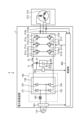
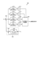
- FIG. 1 is a diagram showing a configuration example of a power conversion device 1 according to Embodiment 1.
- Power converter 1 is connected to AC power supply 110 and compressor 315 .
- the power conversion device 1 converts a first AC voltage of the power supply voltage Vs supplied from the AC power supply 110 into a second AC voltage having a desired amplitude and phase, and supplies the second AC voltage to the compressor 315 .
- the AC power supply 110 may be a single-phase AC power supply or a three-phase AC power supply.
- AC power supply 110 is a single-phase AC power supply will be described as an example.
- the power conversion device 1 includes a voltage detection unit 501, a converter 150, a smoothing unit 200, a voltage detection unit 502, an inverter 310, current detection units 313a and 313b, and a control unit 400.
- Converter 150 includes reactor 120 and rectifier 130 .
- a motor drive device 2 is configured by the power conversion device 1 and the motor 314 included in the compressor 315 .
- the voltage detection unit 501 detects the voltage value of the first AC voltage of the power supply voltage Vs supplied from the AC power supply 110 and outputs the detected voltage value to the control unit 400 .
- Voltage detection unit 501 is a detection unit that detects the power state of the first AC voltage. Note that the voltage detection unit 501 may detect a zero crossing of the first AC voltage as the power state of the first AC voltage.
- the converter 150 rectifies a first AC voltage of the power supply voltage Vs supplied from the AC power supply 110, which is a single-phase AC power supply.
- reactor 120 is connected between AC power supply 110 and rectifying section 130 .
- the rectifying section 130 has a bridge circuit composed of rectifying elements 131 to 134, rectifies a first AC voltage of the power supply voltage Vs supplied from the AC power supply 110, and outputs the rectified first AC voltage.
- the rectifier 130 performs full-wave rectification.
- the smoothing section 200 is connected to the output terminal of the rectifying section 130 .
- Smoothing section 200 has capacitor 210 as a smoothing element, and smoothes the voltage rectified by rectifying section 130 .
- Capacitor 210 is, for example, an electrolytic capacitor, a film capacitor, or the like.
- Capacitor 210 is connected to the output end of converter 150 , more specifically, to the output end of rectification section 130 , and has a capacity to smooth the voltage rectified by rectification section 130 .
- the voltage generated in the capacitor 210 by smoothing does not have the waveform of the full-wave rectification of the AC power supply 110, but has a waveform in which a voltage ripple corresponding to the frequency of the AC power supply 110 is superimposed on the DC component, and does not pulsate greatly.
- the main component of the frequency of this voltage ripple is twice the frequency of the power supply voltage Vs. If the power input from AC power supply 110 and the power output from inverter 310 do not change, the amplitude of this voltage ripple is determined by the capacitance of capacitor 210 . For example, it pulsates in such a range that the maximum value of the voltage ripple generated in the capacitor 210 is less than twice the minimum value.
- capacitor 210 is connected to the output terminal of converter 150 and smoothes the first DC voltage rectified by converter 150 into a second DC voltage containing the first ripple.
- the voltage detection unit 502 detects the DC bus voltage Vdc , which is the voltage across the smoothing unit 200, that is, the capacitor 210, charged by the current rectified by the rectifying unit 130 and flowing into the smoothing unit 200 from the rectifying unit 130. The resulting voltage value is output to the control unit 400 .
- Voltage detection unit 502 is a detection unit that detects a physical quantity correlated with the second DC voltage including the first ripple as the power state of capacitor 210 .
- the voltage detection section 502 may be referred to as a first detection section, and the physical quantity detected by the voltage detection section 502 may be referred to as a first physical quantity.
- the inverter 310 is connected to both ends of the smoothing section 200 , that is, the capacitor 210 .
- Inverter 310 has switching elements 311a-311f and freewheeling diodes 312a-312f.
- Inverter 310 turns switching elements 311a to 311f on and off under the control of control unit 400, and converts the voltage output from rectifying unit 130 and smoothing unit 200 into a second AC voltage having a desired amplitude and phase. is generated and output to the motor 314 of the connected compressor 315 .
- Inverter 310 converts a second DC voltage containing the first ripple into a second AC voltage according to a desired frequency.
- Each of the current detection units 313 a and 313 b detects the current value of one phase out of the three phase currents output from the inverter 310 and outputs the detected current value to the control unit 400 .
- Control unit 400 acquires two-phase current values among the three-phase current values output from inverter 310, thereby calculating the remaining one-phase current value output from inverter 310.
- the current detection units 313 a and 313 b are detection units that acquire a second physical quantity including a third ripple that is correlated with the number of rotations generated by the motor 314 . In the following description, the current detection units 313a and 313b may be referred to as second detection units.
- a compressor 315 is a load having a motor 314 for driving the compressor.
- Motor 314 rotates according to the amplitude and phase of the second AC voltage supplied from inverter 310 to perform compression operation.
- the load torque of the compressor 315 can often be regarded as a constant torque load.
- FIG. 1 shows a case where the motor windings are Y-connected, but this is an example and the present invention is not limited to this.
- the motor windings of the motor 314 may be delta-connection, or may be switchable between Y-connection and delta-connection.
- reactor 120 may be arranged after rectifying section 130 .
- the power conversion device 1 may include a booster section, or the rectifier section 130 may have the function of the booster section.
- the voltage detection units 501 and 502 and the current detection units 313a and 313b may be collectively referred to as detection units.
- the voltage values detected by the voltage detection units 501 and 502 and the current values detected by the current detection units 313a and 313b are sometimes referred to as detection values.
- the control unit 400 acquires the voltage value of the power supply voltage Vs of the first AC voltage from the voltage detection unit 501, acquires the voltage value of the DC bus voltage Vdc of the smoothing unit 200 from the voltage detection unit 502, and obtains the voltage value of the DC bus voltage Vdc of the smoothing unit 200 from the voltage detection unit 502.
- a current value of the second AC voltage having the desired amplitude and phase converted by the inverter 310 is obtained from 313a and 313b.
- Control unit 400 controls the operation of inverter 310, specifically, the on/off of switching elements 311a to 311f included in inverter 310, using the detection values detected by the respective detection units. Also, the control unit 400 controls the operation of the motor 314 using the detection values detected by each detection unit.
- control unit 400 outputs second AC power including pulsation corresponding to the pulsation of current flowing from rectifying unit 130 into capacitor 210 of smoothing unit 200 from inverter 310 to compressor 315 as a load.
- the operation of the inverter 310 is controlled so as to
- the pulsation according to the pulsation of the current flowing into the capacitor 210 of the smoothing section 200 is, for example, the pulsation that varies depending on the frequency of the pulsation of the current flowing into the capacitor 210 of the smoothing section 200 .
- the control unit 400 suppresses the current flowing through the capacitor 210 of the smoothing unit 200 .
- control unit 400 does not have to use all the detection values acquired from each detection unit, and may perform control using some of the detection values.
- Control unit 400 controls the second AC voltage such that a second ripple correlated with the first ripple detected by voltage detection unit 502 is superimposed on the output voltage from inverter 310 .
- the control unit 400 performs control so that any one of the speed, voltage, and current of the motor 314 is in a desired state.
- the motor 314 is used to drive the compressor 315 and the compressor 315 is a hermetic compressor, attaching a position sensor for detecting the rotor position to the motor 314 is structurally and economically advantageous. Since it is difficult, the control unit 400 controls the motor 314 without a position sensor.
- control unit 400 controls the operations of inverter 310 and motor 314 using dq rotation coordinates that rotate in synchronization with the rotor position of motor 314, as will be described later.
- the control unit 400 for suppressing the current flowing through the capacitor 210 of the smoothing unit 200 will be described.
- the input current from rectifying section 130 to capacitor 210 of smoothing section 200 is input current I1
- the output current from capacitor 210 of smoothing section 200 to inverter 310 is output current I2.
- the charge/discharge current of the capacitor 210 of the smoothing section 200 is assumed to be the charge/discharge current I3.
- control unit 400 suppresses charging/discharging current I3 of capacitor 210 by performing control to suppress pulsation of DC bus voltage Vdc .
- Control unit 400 can suppress charge/discharge current I3 of capacitor 210 by adding a current corresponding to pulsation of DC bus voltage Vdc to output current I2.
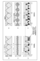
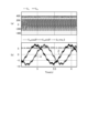
- FIG. 2 is a diagram showing operating states of the power converter 1 according to the presence or absence of control for suppressing the charging/discharging current I3 of the capacitor 210 in the control unit 400 of the power converter 1 according to Embodiment 1.
- FIG. FIGS. 2(a) and 2(b) show the first AC voltage of the power supply voltage Vs supplied from the AC power supply 110 and the rectified voltage outputted from the rectifying section 130, and FIGS. 2(c) and 2(b).
- FIG. 2(d) shows the current flowing from the inverter 310 to the motor 314, and FIGS.
- FIGS. 2(b), 2(d), and 2(f) show states in which the control unit 400 is controlled to suppress the charging/discharging current I3 of the capacitor 210.
- the rectified voltage output from the rectifying section 130 pulsates at a frequency twice the power supply frequency of the AC power supply 110, which is a single-phase AC power supply.
- FIG. 2(b) also shows the same state as FIG. 2(a).
- the pulsation of the DC bus voltage Vdc that is, the pulsation of the charging/discharging current I3 of the capacitor 210, as shown in FIG. It pulsates at a frequency twice the power supply frequency of the AC power supply 110, which is a phase AC power supply.
- the control unit 400 adds a current corresponding to the pulsation of the charge/discharge current I3 of the capacitor 210 to the output current I2, which is the current flowing from the inverter 310 to the motor 314, that is, from the state of FIG.
- the charging/discharging current I3 of the capacitor 210 can be suppressed as shown in FIG. 2(f).
- the power supply frequency of the AC power supply 110 which is a single-phase AC power supply, that is, the fundamental frequency of the first AC voltage is denoted by f
- the frequency twice the power supply frequency of the AC power supply 110 is denoted by the power supply 2f.
- pulsations in various frequency bands are generated depending on the influence of the wiring of the AC power supply 110 and the operating state of the compressor 315 as a load, but they are omitted here.
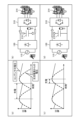
- FIG. 3 is a diagram showing the charge/discharge state of the capacitor 210 in the power conversion device 1 according to Embodiment 1.
- FIG. 3A and 3B when the voltage from AC power supply 110 is smaller than the voltage of capacitor 210 , capacitor 210 discharges, causing motor 314 from capacitor 210 via inverter 310 . current flows through As shown in FIGS. 3(c) and 3(d), when the voltage from the AC power supply 110 is higher than the voltage of the capacitor 210, the discharged amount is charged by the capacitor 210, and the AC voltage 110 is transferred to the rectifying section. 130 and inverter 310 to motor 314 .
- control by control unit 400 to suppress charging/discharging current I3 of capacitor 210 is to reduce the current flowing through capacitor 210 to reduce the capacity of capacitor 210 .
- the power conversion device 1 detects the DC bus voltage Vdc that is correlated with the current of the capacitor 210, and the control unit 400 extracts the pulsation component and suppresses the pulsation.
- the power conversion device 1 By controlling the output of the inverter 310 in such a manner, the current of the capacitor 210 is indirectly reduced.
- the power conversion device 1 since the pulsation of the DC bus voltage Vdc is increased by reducing the capacity of the capacitor 210, the power conversion device 1 has the advantage of having a good S/N (Signal/Noise) ratio in detecting the DC bus voltage Vdc .
- S/N Signal/Noise
- There is Information required for the control of this embodiment is the detected value of the DC bus voltage Vdc and the power supply frequency of the AC power supply 110 .
- the control unit 400 extracts the pulsating frequency component of the DC bus voltage Vdc from the DC bus voltage Vdc and generates a q-axis current command.
- FIG. 4 is a first block diagram showing a configuration for generating a q-axis current command for suppressing pulsation of the DC bus voltage Vdc provided in the control unit 400 of the power converter 1 according to the first embodiment.
- the configuration shown in FIG. 4 is formed by a feedback loop in which the value of the q-axis current command is 0 in order to make the pulsation of the DC bus voltage Vdc zero .
- the DC bus voltage Vdc can be obtained from the detected value of the voltage detector 502 .
- a q-axis current command value of 0 may be abbreviated as a command value of 0.
- the voltage detection unit 502 generally detects the value of the DC bus voltage Vdc divided by the series ratio of the resistors by the control unit 400.
- the ripple component of the DC bus voltage Vdc is The method is not limited as long as the physical quantity contained therein can be detected.
- the control for suppressing the charging/discharging current I3 of the capacitor 210 since the DC component of the DC bus voltage Vdc is not particularly required, it is not always necessary to directly detect the voltage value of the DC bus voltage Vdc by the method described above. .
- Direct detection of the charge/discharge current I3 of the capacitor 210 requires an expensive sensor such as a DCCT (Direct Current Transformer) or an ACCT (Alternating Current Transformer). etc. is an issue.
- circuits for detecting the DC bus voltage Vdc are generally less expensive than current detection, and are easy to introduce because there is no need to worry about loss, heat, and the like.
- the circuit for detecting the DC bus voltage Vdc can be used together with a converter including a booster as in the second embodiment described later.
- the voltage detection unit 502 may detect the DC bus voltage Vdc in synchronization with the carrier of the inverter 310 with respect to the detection timing of the DC bus voltage Vdc .
- the DC bus voltage Vdc may be detected in synchronization with the carrier of the converter.
- Voltage detector 502 samples at a frequency at least twice the power frequency of AC power supply 110 in consideration of the sampling theorem, that is, detects DC bus voltage Vdc at a period faster than twice the power frequency of AC power supply 110. It is good if it can be detected. In this manner, the voltage detection unit 502 detects the physical quantity with a period shorter than the frequency of the first ripple. Also, the voltage detection unit 502 may detect the physical quantity in synchronization with the timing at which the switching elements 311a to 311f of the inverter 310 change in conduction or non-conduction.
- the power conversion device 1 may include a filter at the input end of the control section 400 that acquires the detected value of the DC bus voltage Vdc from the voltage detection section 502 .
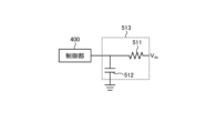
- FIG. 5 is a diagram showing an example of the filter 513 included in the power conversion device 1 according to Embodiment 1. As shown in FIG.
- the power conversion device 1 includes, for example, a filter 513 composed of a resistor 511 and a capacitor 512 .
- the cutoff frequency of the filter 513 must be at least twice the power supply frequency of the AC power supply 110. You can design it. For example, if the resistance value of resistor 511 is 10 k ⁇ and the capacitance of capacitor 512 is 1000 pF, the cutoff frequency of filter 513 is 16 kHz. Note that the power conversion device 1 may have a configuration in which a digital filter is provided inside the control unit 400 instead of the filter 513 shown in FIG.
- the power conversion device 1 uses either an analog filter that attenuates a specific frequency component configured by electronic components or a digital filter that attenuates a specific frequency component by calculation of the control unit 400. Attenuates noise by attenuating specific frequency components of
- the cutoff frequency of the analog filter or digital filter described above is a frequency that is at least twice the frequency of the first ripple.
- the secondary low-pass filter 401 passes the DC component of the DC bus voltage Vdc .
- Subtraction unit 402 removes the DC component from DC bus voltage Vdc by subtracting the DC component of DC bus voltage Vdc that has passed through secondary low-pass filter 401 from DC bus voltage Vdc .
- filter 403 is a kind of high-pass filter that removes the DC component from the DC bus voltage Vdc . Note that the filter 403 is intended to increase the accuracy of extracting the pulsation, which will be described later, so the filter 403 may be omitted.
- a subtraction unit 404 calculates a difference between the command value 0 and the DC bus voltage Vdc from which the DC component has been removed.
- a pulsating component extraction unit 405 extracts a specific frequency component, specifically a cos2f component, from the difference between the command value 0 and the DC bus voltage Vdc after removing the DC component.
- 2f is the power supply frequency of the AC power supply 110, that is, twice the fundamental frequency of the first AC voltage.
- a pulsating component extraction unit 407 extracts a specific frequency component, specifically a sin 2f component, from the difference between the command value 0 and the DC bus voltage Vdc after removing the DC component.
- the pulsation extraction units 405 and 407 extract and reduce only the pulsation of a specific frequency component, thereby suppressing the generation of beats, sidebands, etc., and making the waveform less distorted.
- the control unit 400 multiplies the trigonometric function cos2f of the same frequency as the specific frequency component to be extracted by the pulsation component extraction unit 405, and multiplies the trigonometric function sin2f of the same frequency as the specific frequency component to be extracted by the pulsation component extraction unit 407. , a simple Fourier transform is performed.
- ⁇ 2 ⁇ f1 and f1 is 100 Hz or 120 Hz.
- the pulsation component extraction unit 405 performs the calculation of formula (1)
- the pulsation component extraction unit 407 performs the calculation of formula (2).
- the pulsation component extraction unit 405 removes the sine component by filtering the value obtained by Equation (1) with a low-pass filter.
- the pulsation component extraction unit 407 removes the cos component by filtering the value obtained by Equation (2) with a low-pass filter.
- the amplitude value A of sin( ⁇ t) can be extracted in the pulsation component extraction units 405 and 407 .
- the low-pass filters used in the pulsation component extractors 405 and 407 are designed to have a cutoff frequency of ⁇ /10, for example, because it is sufficient to remove a frequency that is twice the frequency component to be extracted.
- the low-pass filters used in the pulsation component extractors 405 and 407 are not limited to this, and other filters such as a band-pass filter may be used as long as the amplitude value A, which is a DC component, can be extracted.
- the integral control unit 406 performs integral control so that the frequency component extracted by the pulsation component extraction unit 405 becomes zero, and calculates the required current amount.
- the integral control unit 408 performs integral control so that the frequency component extracted by the pulsation component extraction unit 407 becomes zero, and calculates the required current amount. Note that the integral control units 406 and 408 may perform calculations in combination with proportional control, differential control, etc., in addition to integral control. Gain coefficient K used in integral control units 406 and 408 is designed to be an inverse function of the function representing the plant model shown in FIG.
- FIG. 6 is a diagram showing a connection example when the control unit 400 of the power conversion device 1 according to Embodiment 1 has the plant model 420 .
- the actual gain coefficient K varies depending on the specific circuit configuration of the plant model 420 and the like.
- the control unit 400 can realize highly robust control for suppressing the charge/discharge current I3 of the capacitor 210 by the feedback configuration by the integral control units 406 and 408 .
- An AC restoration processing unit 409 receives the calculation results of the integral control units 406 and 408 and restores the calculation results into one AC signal.
- the AC restoration processing unit 409 outputs the restored AC signal as a q-axis current command. For example, if the output from the integral control unit 406 is I q2f-cos and the output from the integral control unit 408 is I q2f-sin , the AC restoration processing unit 409 obtains the q-axis current command I Calculate qd2v .
- I qd2v I q2f ⁇ cos sin(2 ⁇ in t) ⁇ I q2f ⁇ sin cos(2 ⁇ in t) (3)
- the AC restoration processing unit 409 shifts the phase by 90 degrees during the AC restoration because the phase difference between the DC bus voltage Vdc and the charging/discharging current I3 of the capacitor 210 is 90 degrees. Thereby, the control unit 400 can pulsate the q-axis current at the same frequency as the DC bus voltage Vdc , and pulsate the output voltage of the inverter 310 .
- the inventors have found that the effective value of the current flowing through the capacitor 210 can be reduced by causing the inverter 310 to output a pulsation component having the same frequency as the power supply frequency of the AC power supply 110. Confirmed by analysis. The analysis results are as shown in FIG. 2 described above. It can be confirmed that the effective value of the capacitor current is reduced with the control for suppressing the charge/discharge current I3 of the capacitor 210 compared to without the control for suppressing the charge/discharge current I3 of the capacitor 210 . 3 and other examples, the control unit 400 increases the inverter output when the voltage from the AC power supply 110 is high, and decreases the inverter output when the voltage from the AC power supply 110 is low. This is because charging and discharging of 210 is suppressed.
- the control unit 400 suppresses the pulsation of the frequency component twice the fundamental frequency of the first AC voltage.
- the pulsation extractor and the integral controller are arranged in parallel to extract the frequency components of twice and four times the fundamental frequency of the first AC voltage. can be done.
- FIG. 7 is a second block diagram showing a configuration for generating a q-axis current command for suppressing pulsation of the DC bus voltage Vdc provided in the control unit 400 of the power converter 1 according to the first embodiment.
- the configuration shown in FIG. 7 is obtained by adding pulsation component extraction units 410 and 412 and integral control units 411 and 413 to the configuration shown in FIG.
- the pulsating component extraction unit 410 extracts a specific frequency component, specifically a cos4f component, from the difference between the command value 0 and the DC bus voltage Vdc after the DC component has been removed.
- 4f is the power supply frequency of the AC power supply 110, that is, the frequency four times the fundamental frequency of the first AC voltage.
- a pulsating component extraction unit 412 extracts a specific frequency component, specifically a sin4f component, from the difference between the command value 0 and the DC bus voltage Vdc after the DC component has been removed.
- the effects obtained by the pulsating component extracting units 410 and 412 are as described above for the pulsating component extracting units 405 and 407 .
- the integral control unit 411 performs integral control so that the frequency component extracted by the pulsation component extraction unit 410 becomes zero, and calculates the required amount of current.
- the integral control section 413 performs integral control so that the frequency component extracted by the pulsation component extraction section 412 becomes zero, and calculates the required current amount. Note that the integral control units 411 and 413 may perform calculations in combination with proportional control, differential control, etc., in addition to integral control.
- the AC restoration processing unit 409 receives the calculation results of the integration control units 406, 408, 411, and 413 and restores the calculation results into one AC signal.
- the AC restoration processing unit 409 outputs the restored AC signal as a q-axis current command. Thereby, the control unit 400 can pulsate the q-axis current at the same frequency as the DC bus voltage Vdc , and pulsate the output voltage of the inverter 310 .
- control unit 400 has a pulsation component extraction unit that extracts at least one specific frequency component from the physical quantity detected by voltage detection unit 502, and inverter 310 is adjusted so that the extracted frequency component approaches zero. to control the output voltage of the
- the control unit 400 has one or more pulsation component extraction units that extract at least one specific frequency component from the physical quantity detected by the voltage detection unit 502. It is also possible to change the pulsation component extractor for extracting the frequency component. That is, when the control unit 400 includes two or more pulsating portion extracting units capable of extracting frequency components as shown in FIG. 7, the control unit 400 may select and control the pulsating portion extracting unit to be used.
- the control unit 400 adds a q-axis current command necessary for suppressing pulsation of the DC bus voltage Vdc to the existing q-axis current command.
- the existing q-axis current command will be explained.
- the magnetic flux direction of the motor magnet is defined as the d-axis, and the direction leading 90 degrees in electrical angle phase from the d-axis, that is, the direction perpendicular to the d-axis is defined as the q-axis. It is a well-known technology that a current Iq is caused to flow in the motor coil in the q-axis direction to generate a torque in the motor 314 to generate a rotational force.
- control unit 400 of the power conversion device 1 connected to the motor 314 has a speed control unit (not shown) for controlling the motor 314 to a desired rotation speed. Since the configuration of the speed control unit may be a general configuration, detailed description thereof will be omitted. Assuming that the output of the speed control unit is iqpi , the existing q-axis current command iq * is expressed as in equation (4).
- Iqvdc be the amplitude component of the pulsation of the DC bus voltage Vdc
- 2 ⁇ in be the angular velocity at twice the fundamental frequency of the first AC voltage supplied from the AC power supply 110
- the DC bus voltage Vdc the q-axis current command required to suppress the pulsation of the DC bus voltage Vdc is expressed as in equation (5).
- control unit 400 In order to suppress pulsation of DC bus voltage Vdc , control unit 400 generates q-axis current command i q * shown in equation (6) and controls operations of inverter 310, motor 314, and the like. Note that the control unit 400 targets a plurality of frequencies when suppressing the pulsation of the DC bus voltage Vdc , specifically, the frequencies that are twice and four times the fundamental frequency of the first AC voltage. In this case, the q-axis current command i q * shown in Equation (7) may be generated to control the operations of inverter 310, motor 314, and the like.
- iq * iqpi + Iqvdcsin ( 2 ⁇ in + ⁇ )+ Iqvdcsin ( 4 ⁇ in + ⁇ ) (7)
- Control unit 400 does not limit the frequencies to be controlled to twice the fundamental frequency of the first AC voltage to four times the fundamental frequency of the first AC voltage, but to 6 times the fundamental frequency of the first AC voltage.
- One or more multiples of the fundamental frequency of the first alternating voltage may be of interest, such as times, eight times the fundamental frequency of the first alternating voltage. That is, the control unit 400 superimposes, on the inverter output, pulsation of harmonic components of two times the fundamental frequency of the first AC voltage and one or more orders of multiples of the fundamental frequency of the first AC voltage.
- the frequency of the first ripple is twice the fundamental frequency of the first AC voltage, which is the power supply frequency of the AC power supply 110 .
- the frequency of the first ripple is the sum of the frequency component twice the fundamental frequency of the first AC voltage, which is the power supply frequency of the AC power supply 110, and the frequency component of the order multiple.
- control unit 400 may add a q-axis current command for vibration suppression control of the motor 314 to the q-axis current command i q * shown in Equation (6) or Equation (7).
- Load pulsation caused by the rotation of the motor 314 of the compressor 315 can be suppressed by a q-axis current command output by a pulsation compensator as disclosed in Japanese Patent No. 6537725, for example. Therefore, the control unit 400 only needs to have such a pulsation compensation unit.
- the control unit 400 controls the second AC voltage so that the output voltage from the inverter 310 is superimposed on the fourth ripple, which is correlated with the above-mentioned third ripple. Therefore, when the q-axis current command for vibration suppression control is added to the q-axis current commands of equations (6) and (7), they are represented by equations (9) and (10), respectively.
- iq * iqpi + Iqvdcsin ( 2 ⁇ in + ⁇ )+ Iqvdcsin ( 4 ⁇ in + ⁇ )+ Iqavssin ( ⁇ m + ⁇ ) (10)
- Control unit 400 generates q-axis current command i q * shown in equation (9) or equation (10) in order to suppress pulsation of DC bus voltage Vdc and perform vibration suppression control, and inverter 310, It controls the operation of the motor 314 and the like.
- q-axis current command i q * shown in equation (9) or equation (10) in order to suppress pulsation of DC bus voltage Vdc and perform vibration suppression control, and inverter 310, It controls the operation of the motor 314 and the like.
- the control unit 400 sets a limit value for each control q-axis current command.
- Methods of setting the limit values include, for example, a method of determining priority and allocating the q-axis current each time, a method of distributing the q-axis current at a predetermined ratio from the beginning, and the like.
- the priority is determined, for example, i qpi >I qvdc >I qavs .
- control unit 400 does not limit the q-axis current command iqpi from the speed control unit, and uses the remaining current amount obtained by subtracting the q-axis current command iqpi from the maximum current amount as the pulsation of the DC bus voltage Vdc. It may be distributed to the q-axis current command I qvdc for suppression and the q-axis current command I qavs from the pulsating load compensator.
- FIG. 8 is a first diagram showing the ratio of the amount of current for each control to the q-axis current command i q * by the control unit 400 of the power converter 1 according to the first embodiment.
- FIG. 8 is a first diagram showing the ratio of the amount of current for each control to the q-axis current command i q * by the control unit 400 of the power converter 1 according to the first embodiment.
- FIG. 9 is a second diagram showing the ratio of the amount of current for each control to the q-axis current command i q * by the control unit 400 of the power converter 1 according to the first embodiment. 8 and 9 deal with equation (9), and I qvdc2 represents I qvdc sin(2 ⁇ in + ⁇ ).
- the control unit 400 allocates the q-axis current command i qpi and the q-axis current command I qvdc2 to the maximum current amount as they are, and allocates the remaining current amount to the q-axis current command I qavs . good too. Further, as shown in FIG.
- control unit 400 assigns the q-axis current command i qpi as it is to the maximum current amount, and assigns the remaining current amount to the q-axis current command I qvdc2 and the q-axis current command I qavs . It may be divided into two and allocated. Control unit 400 allocates q-axis current command i qpi to the maximum current amount as it is, and assigns the remaining current amount to q-axis current commands I qvdc2 , q It may be equally divided into three and assigned to the axis current command I qvdc4 and the q-axis current command I qavs . Note that I qvdc4 represents I qvdc sin(4 ⁇ in + ⁇ ).
- the control unit 400 basically gives priority to the q-axis current command i qpi because the desired rotation of the motor 314 cannot be maintained if the current of the q-axis current command i qpi output from the speed control unit is limited.
- a limit may be added to the q-axis current command iqpi depending on the application, such as the desire to continue the operation even if the rotation speed of the motor 314 is reduced.
- the control unit 400 may freely set the ratio for each control in FIGS. 8 and 9 according to the purpose. For example, the control unit 400 may allocate a large amount of current to the q-axis current command Iqavs when vibration is noticeable at low speed. Thus, control unit 400 changes the ratio of the second ripple and the fourth ripple superimposed on the output voltage from inverter 310 at a specified ratio.
- control unit 400 superimposes on the inverter output a pulsation containing the same frequency component as the pulsation of the DC bus voltage Vdc generated by the AC power supply 110, which is a single-phase AC power supply, so that the pulsation of the DC bus voltage Vdc is reduced. can be reduced.
- the control unit 400 uses the power supply frequency of the AC power supply 110, which is a single-phase AC power supply, that is, twice the fundamental frequency of the first AC voltage, as the aforementioned frequency component.
- control unit 400 uses the detection value of the voltage detection unit 501 to periodically calculate the fundamental frequency of the first AC voltage, which is the power supply frequency of the AC power supply 110, which is a single-phase AC power supply.
- the power supply frequency of the AC power supply 110 may fluctuate slightly even during the day. Therefore, by periodically calculating the fundamental frequency of the first AC voltage, which is the power supply frequency of the AC power supply 110, the control unit 400 can improve the accuracy of the control described above.
- FIG. 10 is a diagram showing an example of the relationship between the frequency and the effective value of the current in capacitor 210 when control is performed to suppress charging/discharging current I3 in capacitor 210 in power converter 1 according to Embodiment 1. . As shown in FIG.
- the effect of the control for suppressing the charging/discharging current I3 of the capacitor 210 decreases with an error of about 0.1 Hz, that is, the current of the capacitor 210 increases. Therefore, the power converter 1 must always correctly detect the power supply frequency of the AC power supply 110 in order to obtain the desired effect in the control for suppressing the charging/discharging current I3 of the capacitor 210 .
- the pulsating component extraction units 405 and 407 extract the values obtained by the equations (1) and (2) as A sin component and a cos component are removed by filtering with a low-pass filter, and an amplitude value A of sin( ⁇ t) is extracted.
- the DC bus voltage V dc after the DC component is removed is represented by Equation (11).
- a sin ( ⁇ t + ⁇ t) A sin ( ⁇ t) cos ( ⁇ t) + A cos ( ⁇ t) sin ( ⁇ t) (11)
- Equation (13) is obtained by multiplying 2sin( ⁇ t) by the minute extraction unit 407 .
- the pulsation component extractors 405 and 407 remove the sine component and cosine component by filtering the values obtained by the equations (12) and (13) with a low-pass filter.
- the amplitude value A containing the ⁇ component of sin( ⁇ t+ ⁇ t) can be extracted in the pulsation component extraction units 405 and 407 .
- the DC bus voltage Vdc after removal of the DC component when the double frequency of the power supply frequency of the AC power supply 110 is 101 Hz is represented by Equation (14).
- FIG. 11 is a diagram showing a specific example of pulsation component extraction in the power converter 1 according to the first embodiment.
- Vin indicates the power supply frequency of the AC power supply 110
- Vdc indicates the DC bus voltage.
- ⁇ represents Asin(2 ⁇ 1t) in the first term on the right side of Equation (15)
- ⁇ represents Acos(2 ⁇ 1t) in the first term on the right side of Equation (16).
- the control unit 400 detects the primary voltage or zero crossing of the AC power supply 110 and periodically calculates the power supply frequency of the AC power supply 110, and continuously updates the power supply frequency of the AC power supply 110 recognized by the control unit 400. Since the control unit 400 may not be able to calculate the correct power supply frequency due to the effects of noise, delay of the detection circuit, etc. in the zero-crossing detection, generally a moving average of several times is used.
- the control unit 400 performs zero-cross detection on the extracted pulsation component, for example, V dc cos2f in FIG. If it can be corrected to 101 Hz, frequency calculation by zero cross detection of AC power supply 110 becomes unnecessary.
- the voltage detection unit 501 is assumed to be a third detection unit that detects a third physical quantity correlated with the voltage value of the first AC voltage.
- control unit 400 periodically calculates the fundamental frequency of the first AC voltage, which is the power supply frequency of AC power supply 110 , from the third physical quantity detected by voltage detection unit 501 .
- the voltage detection unit 501 is a fourth detection unit that detects whether the voltage value of the first AC voltage, which changes with the passage of time, exceeds or falls below a specified value.
- control unit 400 periodically calculates the fundamental frequency of the first AC voltage, which is the power supply frequency of AC power supply 110 , from the output signal of voltage detection unit 501 .
- the control unit 400 sets the average value of the values calculated from the output signal of the voltage detection unit 501 two or more times as the fundamental frequency of the first AC voltage, which is the power supply frequency of the AC power supply 110 .
- control unit 400 acquires a physical quantity correlated with the DC bus voltage Vdc (step S1).
- control unit 400 identifies the first ripple included in DC bus voltage Vdc (step S2).
- Control unit 400 generates a q-axis current command so as to superimpose the first ripple and the correlated second ripple on the output voltage from inverter 310 (step S3).
- FIG. 13 is a diagram showing an example of a hardware configuration that implements the control unit 400 included in the power converter 1 according to Embodiment 1. As shown in FIG. Control unit 400 is implemented by processor 91 and memory 92 .
- the processor 91 is a CPU (Central Processing Unit, central processing unit, processing unit, arithmetic unit, microprocessor, microcomputer, processor, DSP (Digital Signal Processor)), or a system LSI (Large Scale Integration).
- the memory 92 includes RAM (Random Access Memory), ROM (Read Only Memory), flash memory, EPROM (Erasable Programmable Read Only Memory), EEPROM (registered trademark) (Electrically Erasable Programmable Read Non-volatile or volatile such as Only Memory)
- RAM Random Access Memory
- ROM Read Only Memory
- flash memory flash memory
- EPROM Erasable Programmable Read Only Memory
- EEPROM registered trademark
- a semiconductor memory can be exemplified.
- the memory 92 is not limited to these, and may be a magnetic disk, an optical disk, a compact disk, a mini disk, or a DVD (Digital Versatile Disc).
- voltage detection unit 502 detects DC bus voltage Vdc
- control unit 400 detects the voltage generated by AC power supply 110, which is a single-phase AC power supply.
- a pulsation containing the same frequency component as the pulsation of the DC bus voltage Vdc that is, a pulsation having a frequency twice the fundamental frequency of the first AC voltage, which is the power supply frequency of the AC power supply 110, is superimposed on the inverter output. Ripple of the voltage Vdc can be reduced.
- the power conversion device 1 can suppress an increase in the size of the device while suppressing deterioration of the smoothing capacitor 210 .
- the power conversion device 1 can reduce the cost of the detection circuit compared to the case where the current flowing through the capacitor 210 is directly detected. , can be easily introduced because there is no need to worry about the effects of heat.
- the power conversion device 1 since the DC bus voltage Vdc detected by the voltage detection unit 502 is the voltage smoothed by the capacitor 210, the power conversion device 1 uses PWM ( High-frequency ripple countermeasures by Pulse Width Modulation are not required.
- PWM High-frequency ripple countermeasures by Pulse Width Modulation are not required.
- the power conversion device 1 increases the S/N ratio of the pulsation component to be controlled, thereby facilitating detection.
- the power conversion device 1 is capable of highly robust control because the control unit 400 performs feedback control.
- the control unit 400 extracts and controls a specific frequency component, the power conversion device 1 can perform control with reduced waveform distortion.
- Embodiment 2 A second embodiment will explain a case where the converter includes a booster circuit.
- FIG. 14 is a first diagram showing a configuration example of a power conversion device 1a according to Embodiment 2.
- FIG. Power converter 1a is obtained by replacing converter 150 and control unit 400 with converter 150a and control unit 400a in power converter 1 of Embodiment 1 shown in FIG.
- Converter 150 a includes reactor 120 , rectifying section 130 , and boosting section 140 .
- the boosting unit 140 includes a reactor 141, a switching element 142, and a rectifying element 143, and constitutes a booster circuit.
- the boosting unit 140 boosts the voltage rectified by the rectifying unit 130 by controlling the ON/OFF of the switching element 142 by the control unit 400a. Since the boosting operation of the boosting unit 140 may be a general one, detailed description thereof will be omitted.
- the control unit 400 a has the function of controlling on/off of the switching element 142 of the boosting unit 140 as well as the function of the control unit 400 . That is, control unit 400 a controls the operation of converter 150 a including boost unit 140 .
- the power converter 1a and the motor 314 included in the compressor 315 constitute a motor drive device 2a.
- the power conversion device 1a is equipped with a booster circuit to increase the DC bus voltage Vdc .
- the amount of current that can be used for the q-axis current can be increased.
- the power conversion device 1a can increase the current that can be allocated to Iqvdc even under the same load conditions, rotation speed, etc., and reduces the pulsation of the DC bus voltage Vdc. can enhance the effect of suppressing Power converter 1a needs to detect the voltage boosted by booster 140, but since it includes voltage detector 502 for detecting DC bus voltage Vdc , new detection is performed in the second embodiment. No need to add parts.
- the configuration in which the converter of the power conversion device has the boost function is not limited to the example of FIG. 14 .
- the converter 150 of the power converter 1 of Embodiment 1 is a passive circuit made up of passive components, and the value of the DC bus voltage Vdc is determined by the amplitude value of the first AC voltage supplied from the AC power supply 110. was the method. However, in Embodiment 1, it is sufficient if the pulsation of the DC bus voltage Vdc can be detected correctly and the pulsation having the same frequency component as the pulsation can be output from the inverter 310 .
- the rectifying elements 131 to 134 such as diodes are replaced with semiconductor elements, that is, active elements such as switching elements to form a booster circuit, and the control unit 400 or the like controls the operation of the active elements.
- FIG. 15 is a second diagram showing a configuration example of the power converter 1b according to the second embodiment.
- Power conversion device 1b is obtained by replacing converter 150 and control section 400 with converter 150b and control section 400b in power conversion device 1 of Embodiment 1 shown in FIG.
- Converter 150b includes reactor 120 and rectifier 130b.
- the rectifying section 130b has switching elements 161-164.
- the switching elements 161 to 164 are semiconductor elements, for example, and are turned on and off under the control of the control section 400b.
- the rectifying section 130b can boost and output a voltage by turning on and off the switching elements 161-164.
- the control unit 400b has the function of the control unit 400 as well as the function of controlling on/off of the switching elements 161 to 164 of the rectifying unit 130b.
- control unit 400b controls the operation of converter 150b.
- the rectifying unit 130b may have a configuration in which some of the four elements are switching elements and the other elements are rectifying elements such as diodes. Also in this case, the same effects as those of the power converter 1a shown in FIG. 14 can be obtained.
- the power converter 1b and the motor 314 included in the compressor 315 constitute a motor driving device 2b.
- the converter 150a in the power converter 1a or the converter 150b in the power converter 1b has at least one switching element.
- voltage detection unit 502 may detect the physical quantity in synchronization with the timing at which the conduction or non-conduction of the switching element of converter 150a or converter 150b changes.
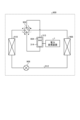
- FIG. 16 is a diagram showing a configuration example of a refrigeration cycle equipment 900 according to Embodiment 3.
- a refrigerating cycle applied equipment 900 according to the third embodiment includes the power converter 1 described in the first embodiment.
- the refrigerating cycle applied equipment 900 can also include the power conversion device 1a or the power conversion device 1b described in the second embodiment, but here, as an example, the case of including the power conversion device 1 will be described.
- the refrigerating cycle applied equipment 900 according to Embodiment 3 can be applied to products equipped with a refrigerating cycle, such as air conditioners, refrigerators, freezers, and heat pump water heaters.
- constituent elements having functions similar to those of the first embodiment are assigned the same reference numerals as those of the first embodiment.
- Refrigerating cycle applied equipment 900 includes compressor 315 incorporating motor 314 according to Embodiment 1, four-way valve 902, indoor heat exchanger 906, expansion valve 908, and outdoor heat exchanger 910 with refrigerant pipe 912. attached through
- a compression mechanism 904 that compresses the refrigerant and a motor 314 that operates the compression mechanism 904 are provided inside the compressor 315 .
- the refrigeration cycle applied equipment 900 can perform heating operation or cooling operation by switching operation of the four-way valve 902 .
- the compression mechanism 904 is driven by a variable speed controlled motor 314 .
- the refrigerant is pressurized by the compression mechanism 904 and sent out through the four-way valve 902, the indoor heat exchanger 906, the expansion valve 908, the outdoor heat exchanger 910, and the four-way valve 902. Return to compression mechanism 904 .
- the refrigerant is pressurized by the compression mechanism 904 and sent through the four-way valve 902, the outdoor heat exchanger 910, the expansion valve 908, the indoor heat exchanger 906, and the four-way valve 902. Return to compression mechanism 904 .
- the indoor heat exchanger 906 acts as a condenser to release heat, and the outdoor heat exchanger 910 acts as an evaporator to absorb heat.
- the outdoor heat exchanger 910 acts as a condenser to release heat, and the indoor heat exchanger 906 acts as an evaporator to absorb heat.
- the expansion valve 908 reduces the pressure of the refrigerant to expand it.
Landscapes
- Engineering & Computer Science (AREA)
- Power Engineering (AREA)
- Physics & Mathematics (AREA)
- Mechanical Engineering (AREA)
- Thermal Sciences (AREA)
- General Engineering & Computer Science (AREA)
- Inverter Devices (AREA)
- Control Of Ac Motors In General (AREA)
- Control Of Motors That Do Not Use Commutators (AREA)
Abstract
Description
図1は、実施の形態1に係る電力変換装置1の構成例を示す図である。電力変換装置1は、交流電源110および圧縮機315に接続される。電力変換装置1は、交流電源110から供給される電源電圧Vsの第1の交流電圧を所望の振幅および位相を有する第2の交流電圧に変換し、圧縮機315に供給する。交流電源110は、単相交流電源であってもよいし、三相交流電源であってもよい。以降では、交流電源110が単相交流電源の場合を例にして説明する。電力変換装置1は、電圧検出部501と、コンバータ150と、平滑部200と、電圧検出部502と、インバータ310と、電流検出部313a,313bと、制御部400と、を備える。コンバータ150は、リアクトル120と、整流部130と、を備える。なお、電力変換装置1、および圧縮機315が備えるモータ314によって、モータ駆動装置2を構成している。
=2Acos(ωt)sin(ωt)cos(Δωt)+2Acos2(ωt)sin(Δωt)
=Asin(Δωt)+Acos(2ωt)sin(Δωt)+Asin(2ωt)cos(Δωt) …(12)
=2Asin2(ωt)cos(Δωt)+2Asin(ωt)cos(ωt)sin(Δωt)
=Acos(Δωt)-Acos(2ωt)cos(Δωt)+Asin(2ωt)sin(Δωt) …(13)
=Asin(2π1t)+Acos(2π100t)sin(2π1t)+Asin(2π100t)cos(2π1t) …(15)
=Acos(2π1t)-Acos(2π100t)cos(2π1t)+Asin(2π100t)sin(2π1t) …(16)
実施の形態2では、コンバータが昇圧回路を備える場合について説明する。
図16は、実施の形態3に係る冷凍サイクル適用機器900の構成例を示す図である。実施の形態3に係る冷凍サイクル適用機器900は、実施の形態1で説明した電力変換装置1を備える。なお、冷凍サイクル適用機器900は、実施の形態2で説明した電力変換装置1aまたは電力変換装置1bを備えることも可能であるが、ここでは一例として、電力変換装置1を備える場合について説明する。実施の形態3に係る冷凍サイクル適用機器900は、空気調和機、冷蔵庫、冷凍庫、ヒートポンプ給湯器といった冷凍サイクルを備える製品に適用することが可能である。なお、図16において、実施の形態1と同様の機能を有する構成要素には、実施の形態1と同一の符号を付している。
Claims (18)
- 交流電源から供給される第1の交流電圧を整流するコンバータと、
前記コンバータの出力端に接続され、前記コンバータで整流された第1の直流電圧を、第1のリプルを含む第2の直流電圧に平滑化するコンデンサと、
前記コンデンサの両端に接続され、前記第2の直流電圧を所望の周波数に応じた第2の交流電圧に変換するインバータと、
前記第2の直流電圧と相関のある物理量を取得する検出部と、
を備え、
前記第1のリプルと相関のある第2のリプルを前記インバータの出力電圧に重畳するように前記第2の交流電圧を制御する電力変換装置。 - 前記検出部で検出された前記物理量から少なくとも1つの特定の周波数成分を抽出する脈動分抽出部を有し、抽出された前記周波数成分が0に近づくようにインバータの出力電圧を制御する、
請求項1に記載の電力変換装置。 - 前記検出部で検出された前記物理量から少なくとも1つの特定の周波数成分を抽出する脈動分抽出部を1つ以上有し、抽出された前記周波数成分の脈動成分の周期に応じて前記周波数成分を抽出する前記脈動分抽出部を変化させる、
請求項1に記載の電力変換装置。 - 前記インバータはモータに接続され、前記検出部を第1の検出部とし、前記物理量を第1の物理量とし、
さらに、
前記モータによって発生する回転数と相関のある第3のリプルを含む第2の物理量を取得する第2の検出部、
を備え、
前記第3のリプルと相関のある第4のリプルを前記インバータからの出力電圧に重畳するように前記第2の交流電圧を制御する、
請求項1から3のいずれか1つに記載の電力変換装置。 - 前記インバータからの出力電圧に重畳する前記第2のリプルおよび前記第4のリプルの割合を規定された比率で変化させる、
請求項4に記載の電力変換装置。 - 前記第1のリプルの周波数は、前記第1の交流電圧の基本周波数の2倍の周波数成分および次数倍の周波数成分の和である、
請求項1から5のいずれか1つに記載の電力変換装置。 - 前記第1のリプルの周波数は、前記第1の交流電圧の基本周波数の2倍の周波数である、
請求項1から5のいずれか1つに記載の電力変換装置。 - 前記検出部は、前記第1のリプルの周波数よりも短い周期で前記物理量を検出する、
請求項1から7のいずれか1つに記載の電力変換装置。 - 前記検出部は、前記インバータが有するスイッチング素子の導通または非導通が変化するタイミングと同期して前記物理量を検出する、
請求項1から7のいずれか1つに記載の電力変換装置。 - 前記コンバータは、少なくとも1つのスイッチング素子を有する、
請求項1から7のいずれか1つに記載の電力変換装置。 - 前記検出部は、前記コンバータが有するスイッチング素子の導通または非導通が変化するタイミングと同期して前記物理量を検出する、
請求項10に記載の電力変換装置。 - 電子部品によって構成される特定の周波数成分を減衰させるアナログフィルタ、または演算によって特定の周波数成分を減衰させるデジタルフィルタのいずれかを用いて、前記物理量の特定の周波数成分を減衰させる、
請求項1から11のいずれか1つに記載の電力変換装置。 - 前記アナログフィルタまたはデジタルフィルタのカットオフ周波数は、前記第1のリプルの周波数の2倍以上の周波数である、
請求項12に記載の電力変換装置。 - 前記検出部を第1の検出部とし、前記物理量を第1の物理量とし、
さらに、
前記第1の交流電圧の電圧値と相関のある第3の物理量を検出する第3の検出部、
を備え、
前記第3の物理量から、前記第1の交流電圧の基本周波数を定期的に算出する、
請求項1から13のいずれか1つに記載の電力変換装置。 - 前記検出部を第1の検出部とし、
さらに、
時間経過によって変化する前記第1の交流電圧の電圧値が規定された値を超過または下回ったことを検出する第4の検出部、
を備え、
前記第4の検出部の出力信号から、前記第1の交流電圧の基本周波数を定期的に算出する、
請求項1から13のいずれか1つに記載の電力変換装置。 - 2回以上、前記第4の検出部の出力信号から算出した値の平均値を、前記第1の交流電圧の基本周波数とする、
請求項15に記載の電力変換装置。 - 請求項1から16のいずれか1つに記載の電力変換装置を備えるモータ駆動装置。
- 請求項1から16のいずれか1つに記載の電力変換装置を備える冷凍サイクル適用機器。
Priority Applications (4)
| Application Number | Priority Date | Filing Date | Title |
|---|---|---|---|
| CN202180104519.2A CN118302948A (zh) | 2021-12-03 | 2021-12-03 | 电力转换装置、马达驱动装置以及制冷循环应用设备 |
| PCT/JP2021/044502 WO2023100360A1 (ja) | 2021-12-03 | 2021-12-03 | 電力変換装置、モータ駆動装置および冷凍サイクル適用機器 |
| US18/699,694 US20250219559A1 (en) | 2021-12-03 | 2021-12-03 | Power conversion apparatus, motor drive unit, and refrigeration cycle application apparatus |
| JP2023564706A JP7536200B2 (ja) | 2021-12-03 | 2021-12-03 | 電力変換装置、モータ駆動装置および冷凍サイクル適用機器 |
Applications Claiming Priority (1)
| Application Number | Priority Date | Filing Date | Title |
|---|---|---|---|
| PCT/JP2021/044502 WO2023100360A1 (ja) | 2021-12-03 | 2021-12-03 | 電力変換装置、モータ駆動装置および冷凍サイクル適用機器 |
Publications (1)
| Publication Number | Publication Date |
|---|---|
| WO2023100360A1 true WO2023100360A1 (ja) | 2023-06-08 |
Family
ID=86611683
Family Applications (1)
| Application Number | Title | Priority Date | Filing Date |
|---|---|---|---|
| PCT/JP2021/044502 Ceased WO2023100360A1 (ja) | 2021-12-03 | 2021-12-03 | 電力変換装置、モータ駆動装置および冷凍サイクル適用機器 |
Country Status (4)
| Country | Link |
|---|---|
| US (1) | US20250219559A1 (ja) |
| JP (1) | JP7536200B2 (ja) |
| CN (1) | CN118302948A (ja) |
| WO (1) | WO2023100360A1 (ja) |
Families Citing this family (2)
| Publication number | Priority date | Publication date | Assignee | Title |
|---|---|---|---|---|
| JP7345673B2 (ja) | 2020-10-26 | 2023-09-15 | 三菱電機株式会社 | 電力変換装置、モータ駆動装置および冷凍サイクル適用機器 |
| JP7566175B2 (ja) * | 2021-12-10 | 2024-10-11 | 三菱電機株式会社 | 電力変換装置、電動機駆動装置及び冷凍サイクル適用機器 |
Citations (4)
| Publication number | Priority date | Publication date | Assignee | Title |
|---|---|---|---|---|
| JP2009225541A (ja) * | 2008-03-14 | 2009-10-01 | Toshiba Elevator Co Ltd | 電力変換装置の寿命診断装置 |
| JP2009291019A (ja) * | 2008-05-30 | 2009-12-10 | Toyota Motor Corp | 交流モータ用インバータの制御装置 |
| WO2010143514A1 (ja) * | 2009-06-09 | 2010-12-16 | 本田技研工業株式会社 | 負荷駆動システムの制御装置 |
| JP2012213264A (ja) * | 2011-03-31 | 2012-11-01 | Daikin Ind Ltd | モータ駆動装置 |
Family Cites Families (4)
| Publication number | Priority date | Publication date | Assignee | Title |
|---|---|---|---|---|
| JP5670398B2 (ja) * | 2012-09-10 | 2015-02-18 | ファナック株式会社 | 少なくとも2つの抵抗放電手段を有するモータ制御装置 |
| JP7154019B2 (ja) * | 2018-03-08 | 2022-10-17 | ナブテスコ株式会社 | Ac-ac電力変換装置 |
| WO2022091186A1 (ja) * | 2020-10-26 | 2022-05-05 | 三菱電機株式会社 | 電力変換装置、モータ駆動装置および冷凍サイクル適用機器 |
| US20230378867A1 (en) * | 2020-10-26 | 2023-11-23 | Mitsubishi Electric Corporation | Power conversion apparatus, motor drive apparatus, and refrigeration cycle apparatus |
-
2021
- 2021-12-03 CN CN202180104519.2A patent/CN118302948A/zh active Pending
- 2021-12-03 WO PCT/JP2021/044502 patent/WO2023100360A1/ja not_active Ceased
- 2021-12-03 US US18/699,694 patent/US20250219559A1/en active Pending
- 2021-12-03 JP JP2023564706A patent/JP7536200B2/ja active Active
Patent Citations (4)
| Publication number | Priority date | Publication date | Assignee | Title |
|---|---|---|---|---|
| JP2009225541A (ja) * | 2008-03-14 | 2009-10-01 | Toshiba Elevator Co Ltd | 電力変換装置の寿命診断装置 |
| JP2009291019A (ja) * | 2008-05-30 | 2009-12-10 | Toyota Motor Corp | 交流モータ用インバータの制御装置 |
| WO2010143514A1 (ja) * | 2009-06-09 | 2010-12-16 | 本田技研工業株式会社 | 負荷駆動システムの制御装置 |
| JP2012213264A (ja) * | 2011-03-31 | 2012-11-01 | Daikin Ind Ltd | モータ駆動装置 |
Also Published As
| Publication number | Publication date |
|---|---|
| CN118302948A (zh) | 2024-07-05 |
| JP7536200B2 (ja) | 2024-08-19 |
| US20250219559A1 (en) | 2025-07-03 |
| JPWO2023100360A1 (ja) | 2023-06-08 |
Similar Documents
| Publication | Publication Date | Title |
|---|---|---|
| JP7345673B2 (ja) | 電力変換装置、モータ駆動装置および冷凍サイクル適用機器 | |
| WO2023073880A1 (ja) | 電力変換装置、モータ駆動装置および冷凍サイクル適用機器 | |
| JP7536200B2 (ja) | 電力変換装置、モータ駆動装置および冷凍サイクル適用機器 | |
| WO2023084600A1 (ja) | 電力変換装置、モータ駆動装置及び冷凍サイクル適用機器 | |
| WO2022172419A1 (ja) | 電力変換装置、モータ駆動装置および空気調和機 | |
| JP7566175B2 (ja) | 電力変換装置、電動機駆動装置及び冷凍サイクル適用機器 | |
| CN118140404A (zh) | 电力转换装置、马达驱动装置和制冷循环应用设备 | |
| JP7580632B2 (ja) | 電力変換装置、モータ駆動装置および冷凍サイクル適用機器 | |
| US20240039427A1 (en) | Power converting apparatus, motor drive apparatus, and refrigeration cycle application device | |
| WO2023105570A1 (ja) | 電力変換装置、モータ駆動装置及び冷凍サイクル適用機器 | |
| WO2022172418A1 (ja) | 電力変換装置、モータ駆動装置および冷凍サイクル適用機器 | |
| JP7166468B2 (ja) | 電動機駆動装置および冷凍サイクル適用機器 | |
| JP7330401B2 (ja) | 電力変換装置、モータ駆動装置および冷凍サイクル適用機器 | |
| CN118104122A (zh) | 电力转换装置、马达驱动装置以及制冷循环应用设备 | |
| CN118104121A (zh) | 电力转换装置、马达驱动装置以及制冷循环应用设备 | |
| JP7825794B1 (ja) | 電力変換装置、モータ駆動装置および冷凍サイクル適用機器 | |
| WO2023100321A1 (ja) | 電力変換装置、モータ駆動装置及び冷凍サイクル適用機器 | |
| JP7819347B2 (ja) | 電力変換装置、モータ駆動装置および冷凍サイクル適用機器 | |
| WO2023047486A1 (ja) | 電力変換装置、電動機駆動装置及び冷凍サイクル適用機器 | |
| JP7515739B2 (ja) | 電力変換装置、電動機駆動装置及び冷凍サイクル適用機器 | |
| WO2022149210A1 (ja) | 電力変換装置、モータ駆動装置および冷凍サイクル適用機器 | |
| JP7325671B2 (ja) | 電力変換装置、モータ駆動装置および冷凍サイクル適用機器 | |
| JP7834200B2 (ja) | 電力変換装置、モータ駆動装置及び冷凍サイクル適用機器 | |
| US20250219553A1 (en) | Power converting apparatus, motor drive apparatus, and refrigeration-cycle application device | |
| CN118104123A (zh) | 电力转换装置、马达驱动装置以及制冷循环应用设备 |
Legal Events
| Date | Code | Title | Description |
|---|---|---|---|
| 121 | Ep: the epo has been informed by wipo that ep was designated in this application |
Ref document number: 21966439 Country of ref document: EP Kind code of ref document: A1 |
|
| WWE | Wipo information: entry into national phase |
Ref document number: 2023564706 Country of ref document: JP |
|
| WWE | Wipo information: entry into national phase |
Ref document number: 18699694 Country of ref document: US |
|
| WWE | Wipo information: entry into national phase |
Ref document number: 202180104519.2 Country of ref document: CN Ref document number: 202427041127 Country of ref document: IN |
|
| NENP | Non-entry into the national phase |
Ref country code: DE |
|
| 122 | Ep: pct application non-entry in european phase |
Ref document number: 21966439 Country of ref document: EP Kind code of ref document: A1 |
|
| WWP | Wipo information: published in national office |
Ref document number: 18699694 Country of ref document: US |